

Page 1

Page 2

OWNER’S OPERATING MANUAL
ANGLE GRINDER
MODEL G-2240
SPECIFICATIONS
Voltage...................................................................................................230V~50Hz
Rated input....................................................................................................2200W
No load speed...........................................................................................6500min
Grinding wheel..............................................................................................230mm
Spindle thread....................................................................................................M14
Disk bore size.............................................................................................. 22.2mm
Sound pressure level..........................................................L
Sound power level........................................................... LWA108.6dB(A),k=3dB(A)
Vibration levels (Main handle).............................................. 11.598m/s2, K=1.5m/s
Vibration levels (Side handle).................................................5.618m/s2, K=1.5m/s
Nett weight....................................................................................................... 5.4kg
THANK YOU FOR BUYING A RYOBI
97.6dB(A),k=3dB(A)
pA
-1
2
2
ANGLE GRINDER
Your new angle grinder has been engineered and manufactured to Ryobi’s high
standard of dependability, ease of operation and operator safety. Properly cared
for, it will give you years of rugged, trouble free performance. If you use your
angle grinder properly and only for what it is intended, you will enjoy years of
safe, reliable service.
CAUTION: Carefully read through this entire owner’s
manual, paying close attention to the general
safety rules and rules for safe operation,
before using.
KEEP THIS MANUAL FOR FUTURE REFERENCE
1
Page 3
IMPORTANT SAFETY INSTRUCTIONS
GLASSES
SAFETY
WEAR
YOUR
FORESIGHT IS BETTER
THAN NO SIGHT
The purpose of safety rules is to attract your
ttention to possible dangers. The safety symbols
a
and the explanations with them, require your
areful attention and understanding. The safety
c
arnings do not by themselves eliminate any
w
danger. The instruction or warnings they give are
not substitutes for proper accident prevention
measures.
SAFETY ALERT SYMBOL. Indicates
danger, caution or warning. May be used
in conjunction with other symbols or
pictures.
Failure to obey a safety warning can result in
serious injury to yourself or to others. Always follow
the safety precautions to reduce the risk of fire,
electric shock and personal injury.
Do not attempt to operate this tool until you have
read thoroughly and completely understood the
safety rules, etc. contained in this manual. Failure
to comply can result in accidents involving fire,
electric shock or serious personal injury. Save this
Owners Operating Manual and review it frequently
for continual safe operation and for instructing
others who may use this tool.
INTENDED USE
Grinding metals.
Use the tool only for approved applications.
Operations such as cutting, sanding, wire brushing,
polishing are not recommended to be performed
with this power tool. Use of the power tool for
operations different from intended could result in a
hazardous situation.
WARNING
To reduce the risk of injury, the user must
read and understand the operator’s
manual.
WARNING
Do not attempt to operate this tool
until you have read thoroughly and
understood completely all instructions,
safety rules etc contained in this manual.
Failure to comply may result in accidents
involving fire, electric shock or serious
personal injury. Save operator’s manual
and review frequently for continuing safe
operation, and instructing others who
may use this tool.
WARNING
lways use the guard that accompanied
A
the grinder. Comply with mounting and
se instructions and warnings found in
u
he manual for the grinder and ANSI
t
B7.1. Failure to heed these warnings can
result in wheel breakage and serious
personal injury.
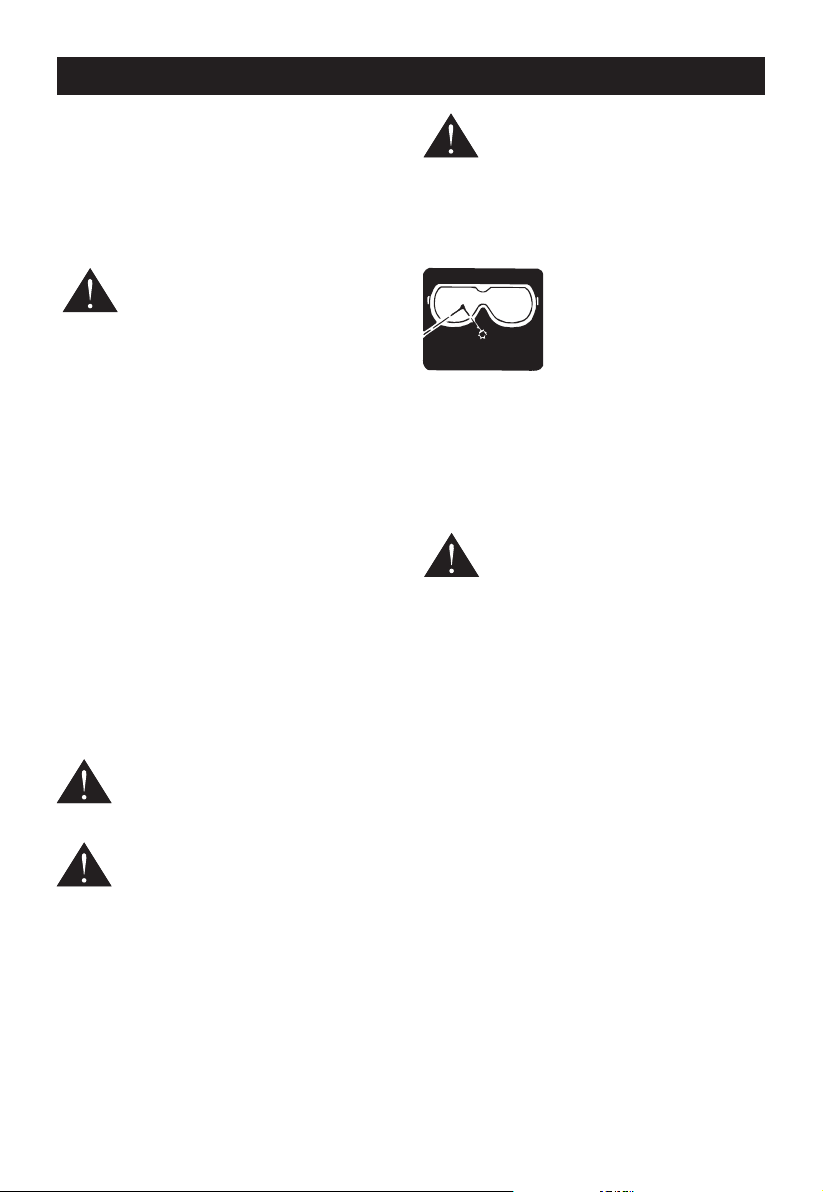
The operation of any angle
grinder can result in foreign
objects being thrown into your
eyes, which can result in
severe eye damage. Before
beginning power tool operation,
safety glasses with side shields and a full face
shield when needed. We recommend Wide Vision
Safety Mask for use over eyeglasses or standard
safety glasses with side shields. Always wear eye
protection which is marked to comply with ANSI
Z87.1.
SPECIFIC SAFETY INSTRUCTIONS
WARNING
The product is not intended for use by
persons (including children) with reduced
physical, sensory or mental capabilities,
or lack of experience and knowledge,
unless they have been given supervision
or instruction concerning use of the
product by a person responsible for their
safety. Children should be supervised to
ensure that they do not play with the
product.
This appliance is not intended for use by young
children or infirm persons. Adequate supervision by
a responsible person must be provided to ensure
that they do not play with the appliance.
Keep children and visitors away. Visitors should
wear safety glasses and be kept a safe distance
from work area. Do not let visitors contact tool or
extension cord.
It is recommended that this tool always be supplied
via a residual current device with a rated residual
current of 30mA or less.
always wear safety goggles or
2
Page 4

IMPORTANT SAFETY INSTRUCTIONS
SAFETY WARNINGS COMMON FOR GRINDING
PERATIONS
O
This power tool is intended to function as a grinder
ool. Read all safety warnings, instructions,
t
llustrations and specifications provided with this
i
power tool. Failure to follow all instructions listed
below may result in electric shock, fire and/or
serious injury.
Operations for which the power tool was not
designed may create a hazard and cause personal
injury.
Do not use accessories which are not specifically
designed and recommended by the tool
manufacturer. Just because the accessory can be
attached to your power tool, it does not assure safe
operation.
The rated speed of the accessory must be at least
equal to the maximum speed marked on the power
tool. Accessories running faster than their rated
speed can break and fly apart.
The outside diameter and the thickness of your
accessory must be within the capacity rating of
your power tool. Incorrectly sized accessories
cannot be adequately guarded or controlled.
The arbour size of wheels, flanges, backing pads
or any other accessory must properly fit the spindle
of the power tool. Accessories with arbour holes
that do not match the mounting hardware of the
power tool will run out of balance, vibrate
excessively and may cause loss of control.
Do not use a damaged accessory. Before each use
inspect the accessory such as abrasive wheels for
chips and cracks, backing pad for cracks, tear or
excess wear, wire brush for loose or cracked wires.
If power tool or accessory is dropped, inspect for
damage or install an undamaged accessory. After
inspecting and installing an accessory, position
yourself and bystanders away from the plane of the
rotating accessory and run the power tool at
maximum no-load speed for one minute. Damaged
accessories will normally break apart during this
test time.
Wear personal protective equipment. Depending
on application, use face shield, safety goggles or
safety glasses. As appropriate, wear dust mask,
hearing protectors, gloves and workshop apron
capable of stopping small abrasive or workpiece
fragments. The eye protection must be capable of
stopping flying debris generated by various
perations. The dust mask or respirator must be
o
capable of filtrating particles generated by your
peration. Prolonged exposure to high intensity
o
oise may cause hearing loss.
n
eep bystanders a safe distance away from work
K
area. Anyone entering the work area must wear
personal protective equipment. Fragments of
workpiece or of a broken accessory may fly away
and cause injury beyond immediate area of
operation.
Hold power tool by insulated gripping surfaces only,
when performing an operation where the cutting
accessory may contact hidden wiring or its own
cord. Cutting accessory contacting a “live” wire
may make exposed metal parts of the power tool
“live” and shock the operator.
Position the cord clear of the spinning accessory. If
you lose control, the cord may be cut or snagged
and your hand or arm may be pulled into the
spinning accessory.
Never lay the power tool down until the accessory
has come to a complete stop. The spinning
accessory may grab the surface and pull the power
tool out of your control.
Do not run the power tool while carrying it at your
side. Accidental contact with the spinning
accessory could snag your clothing, pulling the
accessory into your body.
Regularly clean the power tool’s air vents. The
motor’s fan will draw the dust inside the housing
and excessive accumulation of powdered metal
may cause electrical hazards.
Do not operate the power tool near flammable
materials. Sparks could ignite these materials.
Do not use accessories that require liquid coolants.
Using water or other liquid coolants may result in
electrocution or shock.
Use only wheel types that are recommended for
your power tool and the specific guard designed for
the selected wheel. Wheels for which the power
tool was not designed cannot be adequately
guarded and are unsafe.
3
Page 5

IMPORTANT SAFETY INSTRUCTIONS
The guard must be securely attached to the power
ool and positioned for maximum safety, so the
t
least amount of wheel is exposed towards the
perator. The guard helps to protect operator from
o
roken wheel fragments and accidental contact
b
with wheel.
Wheels must be used only for recommended
applications. For example: do not grind with the
side of cut-off wheel. Abrasive cut-off wheels are
intended for peripheral grinding, side forces applied
to these wheels may cause them to shatter.
Always use undamaged wheel flanges that are of
correct size and shape for your selected wheel.
Proper wheel fl anges support the wheel thus
reducing the possibility of wheel breakage. Flanges
for cut-off wheels may be different from grinding
wheel flanges.
Do not use worn down wheels from larger power
tools. Wheel intended for larger power tool is not
suitable for the higher speed of a smaller tool and
may burst.
KICKBACK AND RELATED WARNINGS
Kickback is a sudden reaction to a pinched or
snagged rotating wheel, backing pad, brush or any
other accessory.
Pinching or snagging causes rapid stalling of the
rotating accessory which in turn causes the
uncontrolled power tool to be forced in the direction
opposite of the accessory’s rotation at the point of
the binding.
For example, if an abrasive wheel is snagged or
pinched by the workpiece, the edge of the wheel
that is entering into the pinch point can dig into the
surface of the material causing the wheel to climb
out or kick out. The wheel may either jump toward
or away from the operator, depending on direction
of the wheel’s movement at the point of pinching.
Abrasive wheels may also break under these
conditions.
Kickback is the result of power tool misuse and/or
incorrect operating procedures or conditions and
can be avoided by taking proper precautions as
given below.
a. Maintain a firm grip on the power tool and
position your body and arm to allow you to
resist kickback forces. Always use auxiliary
handle, if provided, for maximum control over
kickback or torque reaction during startup. The
perator can control torque reactions or
o
kickback forces, if proper precautions are taken.
. Never place your hand near the rotating
b
accessory. Accessory may kickback over your
and.
h
c. Do not position your body in the area where
power tool will move if kickback occurs.
Kickback will propel the tool in direction
opposite to the wheel’s movement at the point
of snagging.
d. Use special care when working corners, sharp
edges etc. Avoid bouncing and snagging the
accessory. Corners, sharp edges or bouncing
have a tendency to snag the rotating accessory
and cause loss of control or kickback.
e. Do not attach a saw chain woodcarving blade or
toothed saw blade. Such blades create frequent
kickback and loss of control.
f. The guard must be securely attached to the
power tool and positioned for maximum safety,
so the least amount of wheel is exposed
towards the operator. The guard helps to
protect operator from broken wheel fragments
and accidental contact with wheel and sparks
that could ignite clothing.
ANGLE GRINDER SAFETY PRECAUTIONS
Check that the speed marked on the grinding
wheel is equal to or greater than the rated speed of
the tool.
Ensure that the dimensions of the grinding wheel
are compatible with the tool and that the wheel fits
the spindle.
Grinding wheels must be stored in a dry place.
Do not store objects on top of the grinding wheels.
Grinding wheels must not be used for any
operation other than grinding.
Inspect the grinding wheel before use to ensure
that it is not chipped or cracked. Chips or cracks
can cause the wheels to shatter, resulting in
possible serious injury.
Ensure that the grinding wheel is correctly mounted
and tightened before use and run the tool at no
load speed for 30 seconds in a safe position.
4
Page 6

IMPORTANT SAFETY INSTRUCTIONS
Stop immediately if there is considerable vibration
r if other defects are detected. If this condition
o
occurs, check the tool to determine the cause.
o not use separate reducing bushings or adapters
D
to adapt large hole grinding wheels.
Check that the workpiece is properly supported.
Ensure that sparks resulting from use do not create
a hazard e.g. do not hit people, or ignite flammable
substances.
Always use protective safety glasses and ear
protectors.
Use other personal protective equipment such as
gloves, apron and helmet when necessary.
Never place the tool on the floor or other surfaces
while it is running. Grinding wheels continue to
rotate after the tool is switched off. Never touch the
wheel or place it on the fl oor or other surfaces
while it is rotating.
The flange and clamp nut must have same outer
diameter.
Use the tool only for approved applications. Never
use coolants or water or use the tool as a fixed
tool.
Grip the tool securely with both hands while
operating.
ELECTRICAL SAFETY
CAUTION! The following states how damage to the
machine and possible injury to people can be
avoided:
Handle the unit with care. Clean the ventilation
slots regularly, follow the maintenance instructions.
Do not overload your device. Work only within the
indicated range of performance. Do not use low
power machines for heavy duty work. Do not use
your device for purposes for which it has not been
designed.
Do not attempt to repair the machine yourself
unless you are qualified to do so. Any work not
specified in this manual may only be carried out by
a qualified service centre.
Only use extension cables that have been
approved for outdoor use and are resistant to
splash water. The core diameter for extension
cables measuring up to 25m must be at least 1.5
m
m
2
and 2.5 mm
,
2
or cables longer than 25m.
f
Always roll the whole cable off the reel before use.
heck the cable for damage.
C
The supply voltage must correspond to the voltage
pecified on the modelplate.
s
Do not abuse the cable. Never move the unit by the
cable or pull the cable to disconnect it from the
mains socket. Keep the cable away from heat, oil
and sharp edges. Ensure that the cable is arranged
so that it cannot be tripped over, stepped on or
have heavy weights rested on it. Make sure the
cable will not be subjected to any damage.
Do not use the machine if the cables are damaged
or worn.
Do not connect a damaged cable to the mains
supply or touch a damaged cable before it is
disconnected from the mains supply. A damaged
cable can lead to an electric shock.
GENERAL SAFETY RULES
WARNING! Read all instructions Failure to follow
all instructions listed below may result in electric
shock, fire and/or serious injury. The term "power
tool" in all of the warnings listed below refers to
your mains operated (corded) power tool or battery
operated (cordless) power tool.
SAVE THESE INSTRUCTIONS
1) WORK AREA
a) Keep work area clean and well lit. Cluttered and
dark areas invite accidents.
b) Do not operate power tools in explosive
atmospheres, such as in the presence of
flammable liquids, gases or dust. Power tools
create sparks which may ignite the dust or
fumes.
c) Keep children and bystanders away while
operating a power tool. Distractions can cause
you to lose control.
2) ELECTRICAL SAFETY
a) Power tool plugs must match the outlet. Never
modify the plug in any way. Do not use any
adapter plugs with earthed (grounded) power
tools. Unmodified plugs and matching outlets
will reduce risk of electric shock.
5
Page 7

IMPORTANT SAFETY INSTRUCTIONS
b) Avoid body contact with earthed or grounded
urfaces such as pipes, radiators, ranges and
s
refrigerators. There is an increased risk of
electric shock if your body is earthed or
rounded.
g
) Do not expose power tools to rain or wet
c
conditions. Water entering a power tool will
increase the risk of electric shock.
d) Do not abuse the cord. Never use the cord for
carrying, pulling or unplugging the power tool.
Keep cord away from heat, oil, sharp edges or
moving parts. Damaged or entangled cords
increase the risk of electric shock.
e) When operating a power tool outdoors, use an
extension cord suitable for outdoor use. Use of
a cord suitable for outdoor use reduces the risk
of electric shock.
3) PERSONAL SAFETY
a) Stay alert, watch what you are doing and use
common sense when operating a power tool.
Do not use a power tool while you are tired or
under the influence of drugs, alcohol or
medication. A moment of inattention while
operating power tools may result in serious
personal injury.
b) Use safety equipment. Always wear eye
protection. Safety equipment such as dust
mask, non-skid safety shoes, hard hat, or
hearing protection used for appropriate
conditions will reduce personal injuries.
c) Avoid accidental starting. Ensure the switch is
in the off position before plugging in. Carrying
power tools with your finger on the switch or
plugging in power tools that have the switch on
invites accidents.
d) Remove any adjusting key or wrench before
turning the power tool on.
A wrench or a key left attached to a rotating part
of the power tool may result in personal injury.
e) Do not overreach. Keep proper footing and
balance at all times. This enables better control
of the power tool in unexpected situations.
f) Dress properly. Do not wear loose clothing or
jewellery. Keep your hair, clothing and gloves
away from moving parts. Loose clothes,
jewellery or long hair can be caught in moving
parts.
g) If devices are provided for the connection of
ust extraction and collection facilities, ensure
d
these are connected and properly used. Use of
these devices can reduce dust related hazards.
4) POWER TOOL USE AND CARE
a) Do not force the power tool. Use the correct
power tool for your application. The correct
power tool will do the job better and safer at the
rate for which it was designed.
b) Do not use the power tool if the switch does not
turn it on and off. Any power tool that cannot be
controlled with the switch is dangerous and
must be repaired.
c) Disconnect the plug from the power source
before making any adjustments, changing
accessories, or storing power tools. Such
preventive safety measures reduce the risk of
starting the power tool accidentally.
d) Store idle power tools out of the reach of
children and do not allow persons unfamiliar
with the power tool or these instructions to
operate the power tool. Power tools are
dangerous in the hands of untrained users.
e) Maintain power tools. Check for misalignment
or binding of moving parts, breakage of parts
and any other condition that may affect the
power tools operation. If damaged, have the
power tool repaired before use. Many accidents
are caused by poorly maintained power tools.
f) Keep cutting tools sharp and clean. Properly
maintained cutting tools with sharp cutting
edges are less likely to bind and are easier to
control.
g) Use the power tool, accessories and tool bits
etc., in accordance with these instructions and
in the manner intended for the particular type of
power tool, taking into account the working
conditions and the work to be performed. Use of
the power tool for operations different from
intended could result in a hazardous situation.
5) SERVICE
a) Have your power tool serviced by a qualified
repair person using only identical replacement
parts. This will ensure that the safety of the
power tool is maintained.
6
Page 8

DESCRIPTION
1
11
10
9
2
3
4
5
6
7
1. Spindle lock button
2. Handle lock button
3. Rear hand grip
4. Power cable
5. On/Off trigger
6. Auxiliary handle
8
7. Hex key
8. Wrench
9. Wheel guard
10. Clamp nut
11. Disc flange
7
Page 9

UNPACKING
CLAMP
NUT
GRINDING
WHEEL
DISC
FLANGE
SPINDLE
SPINDLE
LOCK BUTTON
FLAT(S)
WRENCH
TO
TIGHTEN
TO
LOOSEN
CAUTION. This packaging contains
harp objects. Take care when
s
unpacking. Remove the machine,
ogether with the accessories supplied, from the
t
ackaging. Check carefully to ensure that the
p
machine is in good condition and account for all the
accessories listed in this manual. Also make sure
that all the accessories are complete.
ASSEMBLY
PACKING CONTENTS
• Angle grinder
• Auxiliary handle
• Wheel guard
• Wrench and hex key
• Operator’s manual.
WARNING. If any parts are damaged or
missing, do not operate this product until
the parts are replaced. Use of this
product with damaged or missing parts
could result in serious personal injury.
WARNING. Your grinder should never
be connected to power supply when you
are assembling parts, making
adjustments, installing or removing
grinding wheels, or when not in use.
Disconnecting your grinder will prevent
accidental starting that could cause
serious injury.
WARNING. Do not attempt to modify this
product or create accessories not
recommended for use with this product.
Any such alteration or modification is
misuse and could result in a hazardous
condition leading to possible serious
personal injury.
INSTALLING THE AUXILIARY HANDLE
WARNING. Failure to unplug your grinder
could result in accidental starting causing
serious injury.
Install the auxiliary handle by screwing it into the
side of the gear housing, Fig.1.
Note: The handle can be installed on either the left
or right side or top of the grinder, depending on
operator preference. It must always be used to
prevent loss of control and possible serious injury.
Tighten auxiliary handle securely.
If any parts are found to be missing, the machine
nd its accessories should be returned together in
a
their original packaging to the retailer. Do not throw
he packaging away, keep it safe throughout the
t
uarantee period, then recycle if possible,
g
otherwise dispose of it by the proper means. Do
not let children play with empty plastic bags due to
the risk of suffocation.
Fig. 1
Fig. 2
8
Page 10

ASSEMBLY
INSTALLING A GRINDING WHEEL
NOT INCLUDED) (FIG.2)
(
Y
clamp nut attached to the spindle.
Depress spindle lock button and rotate clamp nut
until spindle locks.
Loosen and remove clamp nut from spindle. Do not
remove disc flange.
Make sure flats on the bottom of disc flange are
engaged with flats on spindle.
Place the grinding wheel over the spindle with the
concave side of the wheel facing up.
Thread the clamp nut on the spindle with the flat
side of the nut facing up. Fit the raised, small
diameter portion of the clamp nut into the hole in
the grinding wheel and finger tighten.
Depress the spindle lock button and rotate the
wheel clockwise until the spindle locks in position.
Securely tighten the clamp nut with the wrench
provided. Do not overtighten.
ADJUSTMENTS
GUARD LOCATION
The guard on your grinder should be correctly
installed depending on which side the handle is
mounted. Never use your grinder without the guard
correctly in place.
WARNING. Failure to unplug your grinder
could result in accidental starting causing
erious injury.
s
our grinder is shipped with the disc flange and
WARNING. Always install grinding wheel
with the depressed center against the
disc flange as shown in Fig 2. Failure to
do so will cause the grinding wheel to
crack when tightening the clamp nut. This
could result in serious personal injury
because of loose particles breaking off
and being thrown from the grinder. Never
use a grinding wheel with a mounting
hole larger than 22.2mm. Do not
overtighten.
WARNING. Before connecting your
grinder to power supply, always check to
be sure switch is not in lock-on position.
Failure to do so could result in accidental
starting of your grinder resulting in
possible serious injury.
A
CORRECT
LOCATION OF GUARD
S BETWEEN POINTS
I
A AND B
Fig. 3
B
Fig. 4
INCORRECT
LOCATION OF GUARD
Fig. 5
Figures 3, 4, and 5 show correct and incorrect
locations of the guard.
WARNING. Never place the guard so
that it is on front of the grinder as shown
in figure 5. This could result in serious
injury because sparks and loose particles
thrown from the grinding wheel would be
directed toward the operator. Always
place the guard in the correct location as
shown in figures 3 and 4.
9
Page 11

OPERATION
ARNING. Always wear safety glasses
W
and keep guard in place when grinding.
ot metal sparks from metal grinding can cause a
H
fire. Avoid spark contact with flammable materials
uch as saw dust or clothing.
s
Grinding wheels must be free of fissures and
cracks. Fissures and cracks can cause a grinding
wheel to shatter resulting in possible serious injury.
Thoroughly inspect a new grinding wheel before it
is installed on the grinder.
1. Use a wooden hammer for the inspection.
2. Using the hammer, lightly tap all around the
wheel, carefully listening to the resulting
sounds.
3. Any places with fissures or cracks will result in
a different sound. Do not use a wheel
containing fissures or cracks. When installing a
new grinding wheel, a no load revolution test of
approximately one minute must be carried out
with the grinding wheel facing a safe direction,
i.e. away from people or objects.
DANGER. Never attach a wood cutting
or carving blade of any type to this angle
grinder. It is only designed for grinding
metal. Use for any other purpose is not
recommended and creates a hazard
which will result in serious injury.
WARNING. Do not allow familiarity with
products to make you careless.
Remember that a careless fraction of a
second is sufficient to inflict injury.
WARNING. Always wear eye protection
with side shields marked to comply with
ANSI Z87.1. Failure to do so could result
in objects being thrown into your eyes,
resulting in possible serious injury.
CONNECTING TO A POWER SUPPLY
Make sure the on/off switch is in its off position.
Connect the plug with a suitable socket.
WARNING. Check the voltage!
The voltage must comply with the
information on the rating label.
CAUTION. Never cover air vents. They
must always be open for proper motor
cooling.
N/OFF TRIGGER
SAFETY LOCK
O
Fig. 6
ANDLE LOCK
H
BUTTON
Fig. 7
ON/OFF TRIGGER
To switch on the unit, press forward the safety lock
and then press the on/off trigger, Fig.6.
To switch off the unit, release the on/off trigger.
ADJUSTING THE ROTATING HANDLE
POSITION
Turn off the tool. Press and hold the handle lock
button, Fig.7, then turn the rotating handle to the
desired position until it snaps in place.
WARNING. Do not adjust the rotating
handle while the tool is in operation.
GRINDING
Always carefully select and use grinding wheels
that are recommended for the material to be
ground. Make sure that the minimum operating
speed of the grinding wheel selected is not less
than 6,500rpm.
The correct grinding wheel should be suitable for
grinding welds, preparing surfaces to be welded,
grinding structural steel, and grinding stainless
steel.
10
Page 12

OPERATION
5º TO 15º
5º TO15º
Secure all work before beginning a grinding
peration.
o
Secure small workpieces in a vise or clamp to a
orkbench.
w
ANGER. Never use your grinder with
D
the guard removed. It has been
designed for use only with the guard
installed. Attempting to use grinder with
guard removed will result in loose
particles being thrown against the
operator resulting in serious personal
injury.
WARNING. Never use your grinder
without wearing eye protection.
Following this rule will reduce the risk of
serious personal injury.
The key to efficient operation begins by controlling
the pressure and surface contact between the
grinding wheel and workpiece. Flat surfaces are
ground at an acute angle, normally between 5 to 15
degrees.
For maximum control, hold the grinder in front and
away from you with both hands, keeping the
grinding wheel clear of the workpiece. Start your
grinder and let the motor and grinding wheel build
up to full speed. Gradually lower grinder until the
grinding wheel contacts the workpiece.
For best results keep the grinder tilted at an angle
from 5 to 15 degrees, Fig.8, and continuously
moving at a steady, consistent pace. Move the
grinder back and forth or up and down over the
work area. Keep the grinder moving so that an
excessive amount of material is not removed from
one area. If the grinder is held in one spot too long,
it will gouge and cut grooves in the workpiece. If
the grinder is held at too sharp an angle, it will also
gouge the workpiece because of concentration of
pressure on a small area.
Use just enough pressure to keep the grinder from
chattering or bouncing. Heavy pressure will
decrease its speed and put a strain on the motor.
Normally the weight of the tool alone is adequate
for most grinding jobs. Use light pressure when
grinding jagged edges or loose bolts where there is
the potential for the grinder to snag on the metal
edge.
Lift the grinder away from the workpiece before
turning your grinder off.
Fig. 8
11
Page 13

MAINTENANCE
GRINDING
WHEEL
GUARD
DISC
FLANGE
CLAMP
SCREW
FLAT(S)
SPINDLE
LOCK BUTTON
SPINDLE
BEARING CAP
CLAMP
NUT
WRENCH
TO
TIGHTEN
TO
LOOSEN
WARNING. To reduce the risk of injury,
urn unit off and disconnect machine
t
from power source before installing and
emoving accessories, before adjusting
r
r changing set-ups or when making
o
repairs. Be sure the trigger switch is in
the OFF position. An accidental start-up
can cause injury.
WARNING. Always wear eye protection
with side shields marked to comply with
ANSI Z87.1. Failure to do so could result
in objects being thrown into your eyes
resulting in possible serious injury.
GENERAL MAINTENANCE
Avoid using solvents when cleaning plastic parts.
Most plastics are susceptible to damage from
various types of commercial solvents and may be
damaged by their use. Use clean cloths to remove
dirt, dust, oil, grease, etc.
WARNING. Do not at any time let brake
fluids, gasoline, petroleum based
products, penetrating oils, etc., come in
contact with plastic parts. Chemicals can
damage, weaken or destroy plastic
which may result in serious personal
injury.
LUBRICATION
All of the bearings in this tool are lubricated with a
sufficient amount of high grade lubricant for the life
of the unit under normal operating conditions.
Therefore, no further lubrication is required.
GUARD REPLACEMENT (FIG.9)
After extended use, the guard may become worn
and need adjustments or replacing. If you drop
your grinder and damage the guard it may also be
necessary for you to replace it.
PROCEED AS FOLLOWS WHEN
REPLACEMENT IS REQUIRED:
Unplug the grinder. Failure to unplug your grinder
could result in accidental starting causing serious
injury.
Remove and reassemble parts as shown in Fig.9.
Depress spindle lock button and rotate clamp nut
until spindle locks.
Using the wrench provided, loosen and remove
clamp nut from spindle.
Remove grinding wheel and disc flange.
Using the hex key, loosen the clamp screw until the
uard can be adjusted or removed.
g
If you are making adjustments, rotate the guard to
ts correct position as shown in figures 3, 4, and 9,
i
then retighten clamp screw securely. Never use
our grinder without the guard in place and
y
properly adjusted. See Fig.3, 4, and 5.
Note: Be sure the tabs on the guard are seated in
the groove in the bearing cap.
If you are replacing the guard, loosen the clamp
screw until the guard can be removed from the
bearing cap.
Place the new guard on the shoulder of the bearing
cap, Fig.9.
Note: If the new guard will not fit, loosen the clamp
screw until the guard slides over the bearing cap.
Fig. 9
12
Page 14

MAINTENANCE
SYMBOL SIGNAL MEANING
DANGER: Indicates an imminently hazardous situation, which, if not avoided, will
result in death or serious injury.
WARNING Indicates a potentially hazardous situation, which, if not avoided, could
result in death or serious injury.
CAUTION Indicates a potentially hazardous situation, which,if not avoided, mayresult
in minor or moderate injury.
CAUTION (Without Safety Alert Symbol) Indicates a situation that may result in
property damage.
Rotate guard to the correct position as shown in
igures 3, 4, and 5.
f
Tighten clamp screw securely.
Note: Be sure the tabs on the guard are seated in
he groove in the bearing cap.
t
Reassemble disc flange, grinding wheel, and clamp
nut.
Refer to "INSTALLING THE GRINDING WHEEL"
instructions on page 9.
Depress the spindle lock button and rotate the
wheel clockwise until the spindle locks in position.
Securely tighten the clamp nut with the wrench
provided.
LUBRICATION
All of the bearings in this tool are lubricated with a
sufficient amount of high grade lubricant for the life
of the unit under normal operating conditions.
Therefore, no further lubrication is required.
REPAIR
his product does not contain any parts that can be
T
repaired by the consumer. Contact a qualified
pecialist to have it checked and repaired.
s
STORAGE
lean the product as described.
C
Store the product and its accessories in a dry,
frost-free place.
Always store the product in a place that is
inaccessible to children.
The ideal storage temperature is between 10°C
and 30°C.
We recommend using the original package for
storage or covering the product with a suitable
cloth to protect it against dust.
SERVICE
Now that you have purchased your tool, should a need ever exist of repair or service, simply contact your
nearest Ryobi Authorised Service Centre or other qualified service organisation. Be sure to provide all
pertinent facts when you call or visit.
SYMBOLS
13
Page 15

SYMBOLS
Safety Alert Symbol
Indicates danger, warning or caution. It means attention!!!
Your safety is involved.
Read Your Operator's
Manual
Your manual contains special messages to bring attention
to potential safety concerns as well as operating and
servicing information. Please read all the information
carefully to ensure satisfaction and safe use.
Wear eye, hearing and
head protection
Wear eye, hearing and head protection when operating
this equipment.
Recycle Symbol
Waste electrical products should not be disposed of with
household waste. Please recycle where facilities exist.
Check with your Local Authority or retailer for recycling
advice.
CE Marking
Conforms to relevant safety standards.
Insulation Symbol Double insulated for additional protection.
Gloves
Wear non-slip, heavy-duty gloves.
WARNING.
Some dust created by power sanding, sawing, grinding, drilling, and other construction activities contains
chemicals known to cause cancer, birth defects or other reproductive harm. Some examples of these
chemicals are:
• lead from lead-based paints,
• crystalline silica from bricks and cement and other masonry products, and
• arsenic and chromium from chemically-treated lumber.
Your risk from these exposures varies, depending on how often you do this type of work. To reduce your
exposure to these chemicals: work in a well ventilated area, and work with approved safety equipment,
such as those dust masks that are specially designed to filter out microscopic particles.
14
Page 16

NOTES
15
 Loading...