

Page 1
G-2200, G-2350
G-2200
G-2350
6986407 (STD)
11-11
Page 2

G-2200
G-2350
3
13
11
1
2
10
4
3
12
11
1
2
10
4
14
13
- 1 -
Page 3

3
4
1
2-a
1
2
4
5
CUT OFF
WHEEL GUARD
6
DIAMOND/ABRASIVE
CUTTING WHEEL
7
8
8
6
GRINDING WHEEL
7
1-a
2-b
4
1
2
14
G-2200
15
G-2350
G-2200
- 2 -
Page 4
5
6
8
SANDING
DISC
SANDING
PAD
SANDING PAD
CLAMP NUT
WIRE
BRUSH
8
3
9
7
7
12
11
- 3 -
Page 5

THANK YOU FOR BUYING A RYOBI PRODUCT.
To en sure your saf ety and satisfa ct io n, care fu ll y re ad
through this OWNER’S MANUAL before using the product.
General Safety Rules
Read all instructions. Failure to follow all instruc-
WARNING!
tions listed below may result in electric shock, re and/or serious
injury. The term “power tool” in all of the warnings listed below
refers to your mains-operated (corded) power tool or batteryoperated (cordless) power tool.
SAVE THESE INSTRUCTIONS
1)
Work area
a) Keep work area clean and well lit
b) Do not operate power tools in explosive atmospheres,
c) Keep children and bystanders away while operating a
2)
Electrical safety
a) Power tool plugs must match the outlet. Never modify
b) Avoid body contact with earthed or grounded surfac-
c) Do not expose power tools to rain or wet conditions.
d) Do not abuse the cord. Never use the cord for carry-
e) When operating a power tool outdoors, use an exten-
3)
Personal safety
a) Stay alert, watch what you are doing and use com-
b) Use safety equipment. Always wear eye protection.
c) Avoid accidental starting. Ensure the switch is in the
d) Remove any adjusting key or wrench before turning
e) Do not overreach. Keep proper footing and balance at
f) Dress properly. Do not wear loose clothing or jewel-
areas invite accidents.
such as in the presence of ammable liquids, gases
Power tools create sparks which may ignite the
or dust.
dust or fumes.
power tool.
the plug in any way. Do not use any adapter plugs
with earthed (grounded) power tools.
and matching outlets will reduce risk of electric shock
es such as pipes, radiators, ranges and refrigerators.
There is an increased risk of electric shock if your body is
earthed or grounded.
Water entering a power tool will increase the risk of electric shock.
ing, pulling or unplugging the power tool. Keep cord
away from heat, oil, sharp edges or moving parts.
Damaged or entangled cords increase the risk of electric
shock.
sion cord suitable for outdoor use.
able for outdoor use reduces the risk of electric shock.
mon sense when operating a power tool. Do not use a
power tool while you are tired or under the inuence
of drugs, alcohol or medication.
tion while operat ing power tools may result in serious
personal injury.
Safe ty equipment such as dust mask, non-skid safety
shoes, hard hat, or hearing protection used for appropriate conditions will reduce personal injuries.
off-position before plugging in.
with your nger on the switch or plugging in power tools
that have the switch on invites accidents.
the power tool on.
rotating part of the power tool may result in personal injury.
all times.
unexpected situations.
lery. Keep your hair, clothing and gloves away from
moving parts.
be caught in moving parts.
Distractions can cause you to lose control.
A wrench or a key left attached to a
This enables better control of the power tool in
Loose clothes, jewellery or long hair can
. Cluttered and dark
Unmodied plugs
Use of a cord suit-
A moment of inatten-
Carrying power tools
g) If devi ces are provided for the connection of d ust
extraction and collection facilities, ensure these are
connected and properly used.
reduce dust-related hazards.
4)
Power tool use and care
a) Do not force the power tool. Use the correct power
tool for your application.
the job better and safer at the rate for which it was designed.
b) Do not use the power tool if the switch does not turn
it on and off.
with the switch is dangerous and must be repaired.
c) Disconnect the plug from the power source and/or the
battery pack from the power tool before making any
adjustments, changing accessories, or storing power
tools.
starting the power tool accidentally.
d) Store idle power tools out of the reach of children and
do not allow persons unfamiliar with the power tool
or these instructions to operate the power tool.
tools are dangerous in the hands of untrained users.
e) Maintain power tools. Check for misalignment or bind-
ing of moving parts, breakage of parts and any other
condition that may affect the power tools operation.
If damaged, have the power tool repaired before use.
Many accidents are caused by poorly maintained power
tools.
f) Keep cutting tools sharp and clean.
tained cutting tools with sharp cutting edges are less likely
to bind and are easier to control.
g) Use the power tool, accessories and tool bits etc., in
accordance with these instructions and in the manner
intended for the particular type of power tool, taking
into account the working conditions and the work to
be performed.
ent from those those intended could result in a hazardous
situation.
5)
Service
a) Have your power tool serviced by a qualied repair
person using only identical replacement parts.
will ensure that the safety of the power tool is maintained.
Safety Warnings for Operations:
a) This power tool is intended to function as a grinder.
Read all s afety warnings, instructions, illustrations
and spec ifica tio ns provi ded wit h thi s power tool .
Failure to follow all instructions listed below may result in
electric shock, re and/or serious injury.
b) Operations such as sanding, wire brushing, polishing
or cutting-off are not recommended to be performed
with this power tool.
tool was not designed may create a hazard and cause
personal injury.
c) Do not use accessorie s whic h are not specifi call y
designed and recommended by the tool manufacturer.
Jus t because th e acc ess ory can be att ach ed to y our
power tool, it does not assure safe operation.
d) The rated speed of the accessory must be at least
equal to the maximum speed marked on the po wer
tool.
can break and y apart.
e) The out si de diameter and the thi ck ne ss of you r
accessory must be within the capacity rating of your
pow er tool.
adequately guarded or controlled.
f) The arbour size of wheels, anges, backing pads or
any other accessory must properly t the spindle of
the power tool.
match the mounting hardware of the power tool will run
out of balance, vibrate excessively and may cause loss of
control.
Any power tool that cannot be controlled
Such preventive safety measures reduce the risk of
Use of the power tool for operations differ-
Accessories running faster than their rated speed
Inc orrec tly size d accessor ies cann ot be
Accessories with arbour holes that do not
Use of these devices can
The correct power tool will do
Prop erly main-
Operations for which the power
Power
This
- 4 -
Page 6

g) Do not use a damaged accessory. Before each use
inspect the accessory such as abrasive wheels for
chi ps and cracks, backing pad for cracks , tea r or
excess wear, wire brush for loose or cracked wires.
If power tool or access ory is d ropp ed, inspect for
dam age or inst all an undamag ed accessory. After
in spect in g an d in st al ling an acces so ry, position
yo ur self and bystande rs awa y from the pl ane of
the rot at ing acc essor y an d run the powe r to ol at
maxi mum no-loa d spee d for one minu te.
accessories will normally break apart during this test time.
h) Wear personal protective equipment. Depending on
application, use face shield, safety goggles or safety
gla sses. As approp ria te, wear dust mask, heari ng
prote ctors, gloves and workshop apron capable of
stopping small abrasive or workpiece fragments.
eye protection must be capable of stopping ying debris
gener ated by variou s opera ti ons . T he dust mask or
respirator must be capable of ltrating particles generated
by your operation. Prolonged exposure to high intensity
noise may cause hearing loss.
i) Kee p bys tan der s a safe di sta nce away from work
ar ea . An yo ne en te ri ng th e work ar ea mu st wear
personal protective equipment.
or of a broken accessory may y away and cause injury
beyond immediate area of operation.
j) Hold power tool by insulated gripping surfaces only,
when perf ormin g an ope ratio n wh er e the cutti ng
accessory may contact hidden wiring or its own cord.
Cut tin g acces sor y con tac ting a “l ive ” wir e may make
exposed metal parts of the power tool “live” and shock the
operator.
k) Position the cord clear of the spinning accessory.
you lose control, the cord may be cut or snagged and your
hand or arm may be pulled into the spinning accessory.
l ) Never lay the power tool down until the accessory
has come to a complete stop.
may grab the surface and pull the power tool out of your
control.
m) Do not run the power tool while carrying it at your
n) Regularly clean the power tool’s air vents.
o) Do not op era te t he po wer too l near fl amm abl e
p) Do not use accessories that require liquid coolants.
Accidental contact with the spinning accessory could
side.
snag your clothing, pulling the accessory into your body.
fan will draw the dust inside the housing and excessive
accu mulation of p owdered metal may cause electrical
hazards.
materials.
Us ing wa te r or oth er li qui d coo lan ts ma y res ult in
electrocution or shock.
Kickback and Related Warnings
Kickb ac k is a sudd en reac ti on to a pin ch ed or s na gged
rotating wheel, backing pad, brush or any other accessory.
Pinching or snagging causes rapid sta lling of the rotating
accessory which in turn causes the uncontrolled power tool to
be forced in the direction opposite of the accessory’s rotation
at the point of the binding.
For example, if an abrasive wheel is snagged or pinched by
the workpiece, the edge of the wheel that is entering into the
pinch point can dig into the surface of the material causing
the wheel to climb out or kick out. The wheel may either jump
towar d or away from the operator, depending on direction
of the wheel’s movement at the point of pinching. Abrasive
wheels may also break under these conditions.
Kickback is the result of power tool misuse and/or incorrect
operating procedures or conditions and can be avoided by
taking proper precautions as given below.
Sparks could ignite these materials.
Fragments of workpiece
The spinning accessory
Dama ged
The
If
The motor’s
a) Maintain a firm grip on the power tool and position
your body and arm to allow you to resist kickback
forces. Always use auxiliary handle, if provided, for
maximum control over kickbac k or torque reaction
during start-up.
react ions or k ickback forces, if proper precautions are
taken.
b) Never place your hand near the rotating accessory.
Accessory may kickback over your hand.
c) Do not position your body in the area where power
tool will move if kickback occurs.
the tool in direction opposite to the wheel’s movement at
the point of snagging.
d) Use special care when working corners, sharp edges
etc . Avoid boun cin g and snagging the accessor y.
Corners, sharp edges or b ouncin g have a tendency to
snag the rotating accessory and cause loss of control or
kickback.
e) Do not atta ch a s aw chai n wo od car vi ng blade or
toothed saw blade.
and loss of control.
Safety Warnings Specic for Grinding Operations:
a) Use only wheel types that are recommended for your
power tool and the specific guard designed for the
selected wheel.
designed cannot be adequately guarded and are unsafe.
b) T he guard must be securely attached to the power
- 5 -
tool and positioned for maximum safety, so the least
amount of wheel is exposed toward s the operator.
The guard helps to protect operator from broken wheel
fragments and accidental contact with wheel.
c) Whe el s mu st be us e d on ly fo r r e co mm e nd ed
applications. For example: do not grind with the side
of cut-off wheel.
peripheral grinding, side forces applied to these wheels
may cause them to shatter.
d) A lways use undam age d whe el flanges that are of
co rr ec t si ze an d sh ap e for you r se le ct ed whe el .
Proper wheel anges support the wheel thus reducing the
possibility of wheel breakage.
e) Do not us e worn do wn whee ls from larg er powe r
INSTRUCTIONS FOR SAFE HANDLING
1. Make sure that the tool is only connected to the voltage
2. Never use the tool if its cover or any bolts are missing. If the
3. Never touch the blade, drill bit, grinding wheel or other mov-
4. Never start a tool when its rotating component is in contact
5. Grinding wheels must be stored in a dry place.
Do not put any object on the wheels.
Grinding wheels must not be used for any operation other
Grinding wheels must be stored and handled with care in
6. Ensure that the wheel is tted in accordance with this man-
7. Ensure that the grindi ng wheel is correctly mounted and
8. Check that the work piece is properly supported.
9. Do not remove the soft paper in the center of the grinding
10. Grip the tool securely with both hands while operating.
Wheel intended for larger power tool is not suitable
tools.
for the higher speed of a smaller tool and may burst.
marked on the rating plate.
cover or bolts have been removed, replace them prior to
use. Maintain all parts in good working order.
ing parts during use.
with the work piece.
than grinding.
accordance with the manufacturer’s instruction.
ual.
tightened before use and run the tool at no-load speed for
30 seconds in a safe position. Stop immediately if there is
considerable vibration or if other defects are detected. If this
condition occurs, check the tool to determine the cause.
wheel. (If the paper has been previously removed, insert
some soft paper or rubb er between grin ding wheel and
ange.)
Th e oper at o r can co nt rol to rq ue
Kickback will propel
Such blades create frequent kickback
Wheels for which the power tool was not
Abrasive cut-off wheels are intended for
Page 7

DESCRIPTION
1. Trigger
2. Safety lock button
3. Spindle lock
4. Wheel guard
5. Wheel guard xing screw
6. Disc ange
7. Clamp nut
8. Spindle shaft
9. Clamp nut wrench
10. Aux. handle
11. Main handle
12. Release button
13. Power-on indicator
14. Lock-on button (G-2200 only)
15. Wheel guard lock lever (G-2350 only)
SPECIFICATIONS
Grinding wheel 230mm 230 mm
Voltage 230v~50Hz 230v~50Hz
Power input 2,200W 2,350W
Spindle M14 M14
No load speed 6,000min
Net weight 4.7 kg 5.4 kg
Do not use wheels having a Maximum permissible circumferential
speed below 4,800 m/min.
G-2200
-1
G-2350
6,500min
-1
STANDARD ACCESSORIES
Wheel guard, Aux. handle, Clamp nut wrench
APPLICATIONS
(Use only for the purposes listed below.)
1. Grinding
2. Cutting
3. Sanding
4. Wire bufng
SWITCH (Fig.1)
This tool is started and stopped by squeezing and releasing the
trigger (1). To prevent the tool from being started accidentally,
the trigger can only be operated if the safety lock button (2) is
pushed forward first. It is not necessary to maintain pressure
on the safety lock onc e the trigger has been moved from its
releasing position.
LOCK-ON (Fig.1-a)
For continuous operation, push the lock button (14) forward while
the trigger is being squeezed. Squeeze again to release the lock.
(G-2200 only)
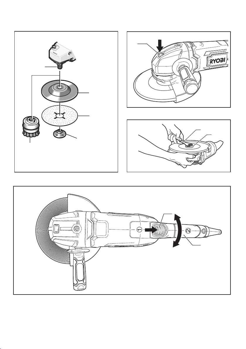
ATTACHING THE WHEEL GUARD
G-2200 (Fig.2-a):
1. Insert the projection on the inside of the wheel guard (4)
clamp into the vertical groove of gear case cover.
2. Adjus t th e position of the wh ee l guard to pr ot ec t the
operator from broken piece of the grinding wheel in case
that the grinding wheel is damaged.
3. Tighten the wheel guard xing screw (5).
G-2350 (Fig.2-b):
1. Release the whee l gua rd lock lever (15) and insert the
projection on the inside of the wheel guard clamp into the
vertical groove of gear case cover.
2. Adjus t th e position of the wh ee l guard to pr ot ec t the
operator from broken piece of the grinding wheel in case
that the grinding wheel is damaged.
3. Push back the wheel guard lock lever to x the wheel guard.
ATTACHING THE GRINDING WHEEL (Fig.3, 6, 7)
WARNING!
Wheel guard must be attac hed when using disc grind ing
wheel s. Always keep wheel guard between you and y our
work while grinding.
1. Attach the disc ange (6), grinding wheel and clamp nut (7)
to the spindle shaft (8).
Be sure tha t th e disc flan ge is p ro perly sea ted on th e
spindle shaft.
2. While pressing the spindle lock (3) on the gear case, rotate
the wheel until it is locked in place.
3. Tighten the clamp nut clockwise with the clamp nut wrench
(9).
CAUTION!
Do not tighten excessively since this can cause cracks in the
grinding wheel.
WARNING!
Check carefully whether or not there are cracks in the wheel.
Replace a cracked wheel immediately.
ATTACHING DIAMOND CUTTING WHEEL
OR ABRASIVE CUTTING WHEEL (Fig. 4, 6, 7)
WARNING!
Do not use water or other cooling fluid with this tool for
cutting.
When using a diamond cutting wheel or an abrasive cutoff
wheel, always use only the wheel guard designed for cut off
work.
NOTE: Cut off wheel guard is not included as a standard
accessory.
1. Attach the disc ange, diamond cutting wheel or abrasive
cutting wheel and clamp nut to the spindle shaft. Be sure
that the disc ange is properly seated on the spindle shaft.
2. While pressing the spindle lock on the gear case, rotate the
wheel until it is locked in place.
3. Tighten the clamp nut clockwise with the clamp nut wrench.
ATTACHING SANDING DISC (Fig. 5, 6, 7)
WARNING!
Before attaching a sanding pad, be sure its maximum safe
operation speed is not exceeded by the speed marked on
rating label on the tool.
Wheel guard may not be used for most sanding operations.
Alway s re insta ll wheel gu ar d when conv ertin g ba ck to
grinding or cutting operations.
NOTE: San di ng pad and sand in g di sc lock nut are not
included as a standard accessory.
- 6 -
Page 8

1. Place the sanding pad onto the spindle shaft, and enter the
sanding disc on top of the sanding pad.
2. Insert the sandi ng disc clamp nut through the disc an d
thread onto the spindle as far as you can with your ngers.
3. Press in the spindle lock, and then tighten the sanding pad
securely with the wrench.
ATTACHING WIRE BRUSH
NOTE: Wire brush is not included as a standard accessory.
1. Place the wire brush onto the spindle shaft.
2. Screw the wire brush by hand until it is securely fastened.
AUX. HANDLE
WARNING!
Alway s use auxili ary han dle for maxi mum contro l over
torque reaction or kick-back.
Operation of the grinder without the side handle could cause
loss of control of the grinder, resulting in possible serious
personal injury.
The aux. handle (10) can be attached to either side of, or the
upp er pa rt of , the gear case, depe nding on prefe ren ce and
conform.
MAIN HANDLE (Fig. 8)
The main handle can be set to any of three positions (0° and 90°
right and left) by rotating the main handle (11) while the release
button (12) is pressed down.
CAUTION!
Before operation, make sure the release button is returned
to lock posi tion, and the ma in hand le is f ix ed in e it her
position.
(G-2350 only)
POWER-ON INDICATOR
The power -on indic ator turns on once the tool is c onnecte d
to electric power supply. This warns the user that the tool is
connected and will operate when the switch is pressed.
OPERATION
KEEP THE WHEEL GUARD IN PLACE.
NEVER COVER AIR VENTS SINCE THEY MUST ALWAYS BE
KEPT OPEN FOR PROPER MOTOR COOLING.
GRINDING
The key t o efficient operating is controllin g the pressure and
surface contact between the disc and work piece. Flat surfaces
are ground at an acute angle, (usually 10 to 20 degrees) to the
work piece. Allow the disc to reach full speed before starting to
grind. Too great an angle causes concentration of pressure on a
small area which may gouge or burn the work surface.
WARNING!
Excessive or sudden pressure on the wheel will slow
grinding action and put dangerous stresses on the wheel.
SANDING
1. For best results, tilt the Disc Sander at a 10° to15° angle
while sanding so that only about 1” of the surface around
the edge of the disc contacts the work.
2. If the disc (accessory) is held at or the back edge of the
disc comes in contact with the work, a violent thrust to the
side may result.
3. If sander is tilted too much, sanding action will be too great
and a rough cut surface or gouging and snagging will result.
4. Guide the Disc Sander with crosswise strokes. Be careful
not to hold the sander in one spot too long. Do not use a
circular motion, as this makes swirl marks. Test before use
on scrap stock.
5. Do not force or apply pressure when sanding. Use only the
weight of the tool for pressure.
Excess pressure actually slows the tool down. If faster stock
removal is desired, change to a coarser grit disc.
6. Remove gummy paint from metal with an “open coat” disc.
Sand until sparks start to appear, then stop and change to a
“closed coat” disc to remove any remaining paint.
a) SANDING WOOD
1. When sanding wood the direction of the disc motion at
the contact point should parallel the gr ain as much as
possible. The rapid cut of discs and the swirl type scratch
pattern they occasionally create generally prohibit their
use for producing the nal nish.
2. Scratches and circula r marks are usually the result of
using too coarse a grit. When c hanging to a finer grit,
mov e ac ros s the san din g lines that were mad e by a
previous coarser disc.
b) SANDING METAL
1. Whe n sa nd ing autom ob il es or ap plian ce s, wipe the
metal clean with a non-ammable solvent or commercial
cleaner to remove all wax and grease. By doing this rst,
the sanding discs will sand better and last longer.
2. For hea vy dut y work, use a coarse grit dis c first, and
foll ow-u p with a m ediu m grit to remo ve scr atch es. To
produce smooth nish, use ne grit disc.
WIRE BRUSHING
1. Wire br us hes are int en ded to “cle an” str uc tural ste el,
castings, sheet metal, stone and concrete. They are used to
remove rust, scale and paint.
2. Avoid bouncing and snagging the wire brush, especially
when working corners, sharp edges, etc. This can cause
loss of control and kickback.
Operate the brush with the lightest pressure so only
NOTE:
the tips of the wire come in c ontact wit h the work.
If heavie r press ur es are us ed , the wires wi ll be
overstressed, resulting in a wiping action; and if this is
continued, the life of the brush will be shortened due
to wire fatigue.
MAINTENANCE
After use, check the tool to make sure that it is in top condition.
It is recommended that you take this tool to a Ryobi Authorized
Service Center for a thorough cleaning and lubrication at least
once per year.
DO NOT MAKE ANY ADJUSTMENTS WHILE THE MOTOR IS
IN MOTION.
ALWAYS DI SCONNEC T THE POWE R CORD FRO M THE
RECEPTACLE
BEFORE CHANGING REMOVABLE OR EXPENDABLE
PARTS (BLADE, BIT, SANDING PAPER ETC.), LUBRICATING
OR WORKING ON THE UNIT.
WARNING!
To en su re sa fe ty and re li ab il it y, all rep ai rs sh ou ld be
performed by an AUTHORIZED SERVICE CENTER or other
QUALIFIED SERVICE ORGANIZATION.
SAVE THESE INSTRUCTIONS FOR FUTURE REFERENCE.
- 7 -
Page 9

NOTE
- 8 -
Page 10

NOTE
- 9 -
Page 11

NOTE
- 10 -
Page 12

RYOBI POWER EQUIPMENT
WARRANTY
Subject to the warranty conditions below, this
RYOBI tool (hereinafter called “the Product”),
is warranted by Ryobi (herein called “the
Company”) to be free from defects in material
or workmanship for a period of 24 months
from the date of original purchase covering
both parts and labour. Under the terms of
this warranty, the repair or replacement of
any part shall be the opinion of the Company
or its authorised agen t. Should service
become necessary during the warrant y
period, the owner should contact the
authorised Ryobi retailer from whom the
product was purchased, or the nearest
Company branch office. In order to obtain
warranty service, the owner must include the
Sales Docket and Warranty Certificate to
confirm date of purchase.
This Product is
sold by the dealer or agent as principal and
the dealer has no authority from the Company
to give any additional warranty or guarantee
on the Company’s behalf except as herein
contained or herein referred to.
Warranty Conditions
This warranty only applies provided that the
Product has been used in accordance with
the manufacturer's recommendations under
normal use and reasonable care (in the
opinion of the Company) and such warranty
does not cover consumable components,
damage, malfunction or failure resulting from
misuse, neglect, abuse, or used for a purpose
for which it was not designed, or is not suited
and no repairs, alterations or modifications
have been attempted by other than a n
Authorised Service Agent. This guarantee
will not apply if the tool is damaged by
accident or if repairs arise from normal wear
and tear.
Accessories such
as bits,blades, sanding
discs, cutting lines, etc., are excluded from
this guarantee. Normal consumable parts,
such as carbon brushes, bearings, chucks,
cord assembly’s, spark plugs, recoil pulleys
and bump head assembly’s are specifically
excluded from this guarantee.
The Company accepts no additional liability
pursuant to this warranty for the costs of
traveling or transportation of the Product or
parts to and from the sevice dealer or agent
- which costs are not included in the warranty.
Nothing herein shall have the effect of
excluding,
restr icting or modifying any
conditions, warranty, right or liability imposed,
to t he extent only that such exclusion,
restriction or modification would render any
term herein void.
THIS WARRANTY FORM
SHOULD BE RETAINED BY THE CUSTOMER AT ALL TIMES.
For your record and to assist in establishing date of purchase (necessary for in-warranty service), please
keep your purchase docket and this form, completed with the following particulars.
PURCHASED FROM:.........................................................................................................
ADDRESS OF DEALER:....................................................................................................
DATE:......................... MODEL NO................................ SERIAL NO.................................
Present this form with your Purchase Docket when Warranty Service is required.
STEVENS & CO (Pty) Ltd
604, 16th Street, Randjespark
Midrand, South Africa
Tel: +27 (11) 357-9600
Fax: +27 (11) 805-5541
email: stevens@ryobi.co.za
P O Box 4059
HALFWAY HOUSE
1685, South Africa
 Loading...