

RuggedCom RuggedSwitch RS950G Hardware Installation Manual

RuggedSwitch™ RS950G
Hardware Installation Guide
Revision 100 - November 2, 2012
www.RuggedCom.com

RuggedSwitch™ RS950G
RuggedSwitch™ RS950G: Hardware Installation Guide
Copyright © 2012 RuggedCom Inc.
All Rights Reserved
Dissemination or reproduction of this document, or evaluation and communication of its contents, is not authorized except where expressly
permitted. Violations are liable for damages. All rights are reserved, particularly for the purposes of patent application or trademark registration.
This document contains proprietary information, which is protected by copyright. All rights are reserved. No part of this document may be
photocopied, reproduced or translated to another language without the prior written consent of RuggedCom Inc.
Disclaimer Of Liability
We have checked the contents of this manual against the hardware and software described. However, deviations from the description cannot
be completely ruled out.
RuggedCom shall not be liable for any errors or omissions contained herein or for consequential damages in connection with the furnishing,
performance, or use of this material.
The information given in this document is reviewed regularly and any necessary corrections will be included in subsequent editions. We appreciate
any suggested improvements. We reserve the right to make technical improvements without notice.
Registered Trademarks
ROX™, RuggedBackbone™, RuggedRated™ and eRSTP™ are trademarks of RuggedCom Inc. ROS®, RuggedRouter® and RuggedSwitch®
are registered trademarks of RuggedCom Inc. Other designations in this manual might be trademarks whose use by third parties for their own
purposes would infringe the rights of the owner.
Third Party Copyrights
RuggedCom recognizes the following third party copyrights:
• Copyright © 2004 GoAhead Software, Inc. All Rights Reserved.
Linux® is the registered trademark of Linus Torvalds in the U.S. and other countries.
The registered trademark Linux® is used pursuant to a sublicense from LMI, the exclusive licensee of Linus Torvalds, owner of the mark on
a world-wide basis.
Warranty
Five (5) years from date of purchase, return to factory. For warranty details, visit www.RuggedCom.com or contact your customer service
representative.
Contacting RuggedCom
Corporate Headquarters US Headquarters Europe Headquarters
RuggedCom Inc.
300 Applewood Crescent,
Concord, Ontario
Canada, L4K 5C7
Tel: +1 905 856 5288
Fax: +1 905 856 1995
Toll-free: 1 888 264 0006
Technical Support
Toll Free (North America): 1 866 922 7975
International: +1 905 856 5288
Email: Support@RuggedCom.com
RuggedCom
1930 Harrison Street, Suite 209
Hollywood, Florida
USA, 33020
Tel: +1 954 922 7938 ext.103
Fax: +1 954 922 7984
Toll-free: 1 888 264 0006
Email: RuggedSales@RuggedCom.com
RuggedCom
Unit 41, Aztec Centre,
Aztec West, Almondsbury, Bristol
United Kingdom BS32 4TD
Tel: +44 1454 203 404
Fax: +44 1454 203 403
Web: www.RuggedCom.com

RuggedSwitch™ RS950G
Table of Contents
FCC Statement And Cautions ................................................................................................... 6
1. Product Overview ................................................................................................................... 7
1.1. Functional Overview .................................................................................................... 7
1.1.1. RS950G Product Features ............................................................................... 7
1.1.2. IEC 62439 - High Reliability Applications ......................................................... 9
1.2. RS950G Front Panel Description .............................................................................. 13
1.3. Bottom Panel Description ......................................................................................... 13
2. Installation ............................................................................................................................ 14
2.1. Panel Mounting ......................................................................................................... 14
2.2. DIN Rail Mounting ..................................................................................................... 15
2.3. Power Supply Wiring and Grounding ........................................................................ 16
2.3.1. AC Power Supply Wiring and Grounding ....................................................... 16
2.3.2. DC Power Supply Wiring and Grounding ....................................................... 17
2.3.3. Failsafe Output Wiring .................................................................................... 17
2.3.4. Dielectric Strength Testing ............................................................................. 18
2.4. Console Port Wiring .................................................................................................. 18
3. Ports ..................................................................................................................................... 19
3.1. Copper Ports ............................................................................................................. 19
3.1.1. Transient Protection ....................................................................................... 19
3.2. Fiber Optic Ports ....................................................................................................... 20
4. Technical Specifications ....................................................................................................... 21
4.1. Operating Environment ............................................................................................. 21
4.2. Power Supply Specifications ..................................................................................... 21
4.3. Failsafe Relay Specifications .................................................................................... 21
4.4. Ethernet Ports Specifications .................................................................................... 22
4.4.1. RJ45 Ethernet Port Specifications .................................................................. 22
4.4.2. Fiber Optic Ethernet Port Specifications ........................................................ 22
4.5. Mechanical Specifications ......................................................................................... 23
5. Type Tests ........................................................................................................................... 24
5.1. IEC 61850-3 Type Tests ........................................................................................... 24
5.2. IEEE 1613 Type Tests .............................................................................................. 25
5.3. IEC Environmental Type Tests ................................................................................. 25
6. Agency Approvals ................................................................................................................ 27
A. Warranty .............................................................................................................................. 28
RuggedCom® RuggedSwitch™ 3 RS950G Installation Guide Rev 100

RuggedSwitch™ RS950G
List of Figures
1.1. Typical HSR Ring Application ............................................................................................. 9
1.2. Typical HSR Inter-Ring Application .................................................................................. 10
1.3. IEEE 1588 Timing in an HSR Application ........................................................................ 11
1.4. HSR with PRP Application ................................................................................................ 12
1.5. RS950G Front Panel Description ..................................................................................... 13
1.6. Bottom Panel Description ................................................................................................. 13
2.1. Panel Mounting ................................................................................................................. 14
2.2. DIN Rail Mounting ............................................................................................................ 15
2.3. AC Power Supply Wiring and Grounding ......................................................................... 16
2.4. DC Power Supply Wiring and Grounding ......................................................................... 17
2.5. Failsafe Relay Output ....................................................................................................... 17
2.6. Dielectric Strength Testing ................................................................................................ 18
2.7. RS232 Female DCE Pinout .............................................................................................. 18
3.1. RJ45 port Pinout ............................................................................................................... 19
3.2. 100FX or 1000LX LC Connector ...................................................................................... 20
4.1. Mechanical Specifications ................................................................................................. 23
RuggedCom® RuggedSwitch™ 4 RS950G Installation Guide Rev 100

RuggedSwitch™ RS950G
List of Tables
1.1. Status LEDs ...................................................................................................................... 13
2.1. RS232 Female DCE Pinout .............................................................................................. 18
3.1. RJ45 Port Pinout .............................................................................................................. 19
4.1. Operating Environment ..................................................................................................... 21
4.2. Power Supply Specifications ............................................................................................. 21
4.3. Failsafe Relay Specifications ............................................................................................ 21
4.4. Failsafe Relay Isolation ..................................................................................................... 21
4.5. RJ45 Ethernet Port Specifications .................................................................................... 22
4.6. Fiber Optic Port Specifications ......................................................................................... 22
4.7. Mechanical Specifications ................................................................................................. 23
5.1. IEC 61850-3 Type Tests ................................................................................................... 24
5.2. IEEE 1613 Type Tests ..................................................................................................... 25
5.3. Environmental Type Tests ................................................................................................ 25
5.4. NEMA TS-2 Requirements ............................................................................................... 26
6.1. Agency Approvals ............................................................................................................. 27
RuggedCom® RuggedSwitch™ 5 RS950G Installation Guide Rev 100
FCC Statement And Cautions
FCC Statement And Cautions
Federal Communications Commission Radio Frequency Interference
Statement
This equipment has been tested and found to comply with the limits for a Class A digital device
pursuant to Part 15 of the FCC Rules. These limits are designed to provide reasonable protection
against harmful interference when the equipment is operated in a commercial environment. This
equipment generates, uses and can radiate radio frequency energy and, if not installed and used in
accordance with the instruction manual, may cause harmful interference to radio communications.
Operation of this equipment in a residential area is likely to cause harmful interference in which
case the user will be required to correct the interference at his own expense.
Caution: LASER
This product contains a laser system and is classified as a CLASS 1 LASER
PRODUCT. Use of controls or adjustments or performance of procedures other than
those specified herein may result in hazardous radiation exposure.
Caution: Service
This product contains no user-serviceable parts. Attempted service by unauthorized
personnel shall render all warranties null and void.
Changes or modifications not expressly approved by RuggedCom Inc. could invalidate
specifications, test results, and agency approvals, and void the user’s authority to
operate the equipment.
Should this device require service, refer to Appendix A, Warranty in this guide.
Caution: Physical Access
This product should be installed in a restricted access location where access can only
be gained by service personnel or users who have been instructed about the reasons
for the restrictions applied to the location and about any precautions that shall be taken;
and access is through the use of a tool or lock and key, or other means of security,
and is controlled by the authority responsible for the location.
RuggedCom® RuggedSwitch™ 6 RS950G Installation Guide Rev 100

1. Product Overview
1. Product Overview
1.1. Functional Overview
The RuggedCom RS950G provides the ultimate in network reliability with Zero-Packet-Loss™
and zero failover time from any network fault. The RS950G supports IEC 62439, High Availability
Seamless Ring (HSR), which is the only Ethernet ring redundancy protocol that truly supporting
“bumpless” failover operation. The RS950G provides complete path redundancy by transmitting
duplicate packets on independent routes through the network. Receiving nodes eliminate any
redundant packets, resulting in a truly seamless failover mechanism not compromised by switch,
cable, or transient failure. The RS950G also provides inter-ring connectivity, allowing scalability
beyond a single ring and providing designers the freedom to create more complex networks.
The RS950G supports the IEEE 1588 v2 Precision Timing Protocol and provides 1µs accuracy
for demanding automation applications, such as IEC 61850-9-2 process bus and motion control.
IEC 61850-3 and IEEE 1613 electric utility substation certifications guarantee that the RS950G
is robust enough to provide uninterrupted operation in the harshest of environments. The
RS950G delivers unprecedented reliability, immunity, and performance for the most missioncritical automation networks where a single lost message can affect operation. The RS950G is
ideal for implementation in utility networks as part of the Smart Grid solution.
1.1.1. RS950G Product Features
Network Resilience
• IEC 62439 HSR and PRP
• Zero-Packet-Loss™ provides 100% packet retention and “bumpless” zero recovery time from
any network fault
Substation Rated
• IEC 61850-3
• IEEE 1613 Class 2
• -40 to +85C operating (no fans)
• Zero-Packet-Loss™
Industrial Design
• Panel or DIN mounting
• Dual DC inputs:
• Order code 24: 9 to 36 VDC
• Order code 48: 37 to 72 VDC
• Universal AC input:
• Order code HI: 85 to 264 VAC
• 20 AWG steel enclosure
RuggedCom® RuggedSwitch™ 7 RS950G Installation Guide Rev 100

1. Product Overview
Management
• Radius or TACACS user authentication
• SSH/SSL encryption
• Web-based, Telnet, CLI, SNMP, RMON
• Alarms, Critical Relay
Performance
• IEEE 1588 v2 Precision Timing Protocol support
• Wire-speed Gigabit throughput with cut-through switching to minimize latency
• Synchronous Ethernet guarantees 1µs accuracy with any network size
• Connect multiple rings and preserve redundancy (Quadbox or Quad Mode operation)
• 8 Class-of-Service queues for QoS prioritization
Support and Service
• 5 Year Warranty
• Global 24×7×365 Technical Action Center
• Personalized Support
RuggedCom® RuggedSwitch™ 8 RS950G Installation Guide Rev 100
1. Product Overview
1.1.2. IEC 62439 - High Reliability Applications
1.1.2.1. High Availability Seamless Ring (HSR) Operation
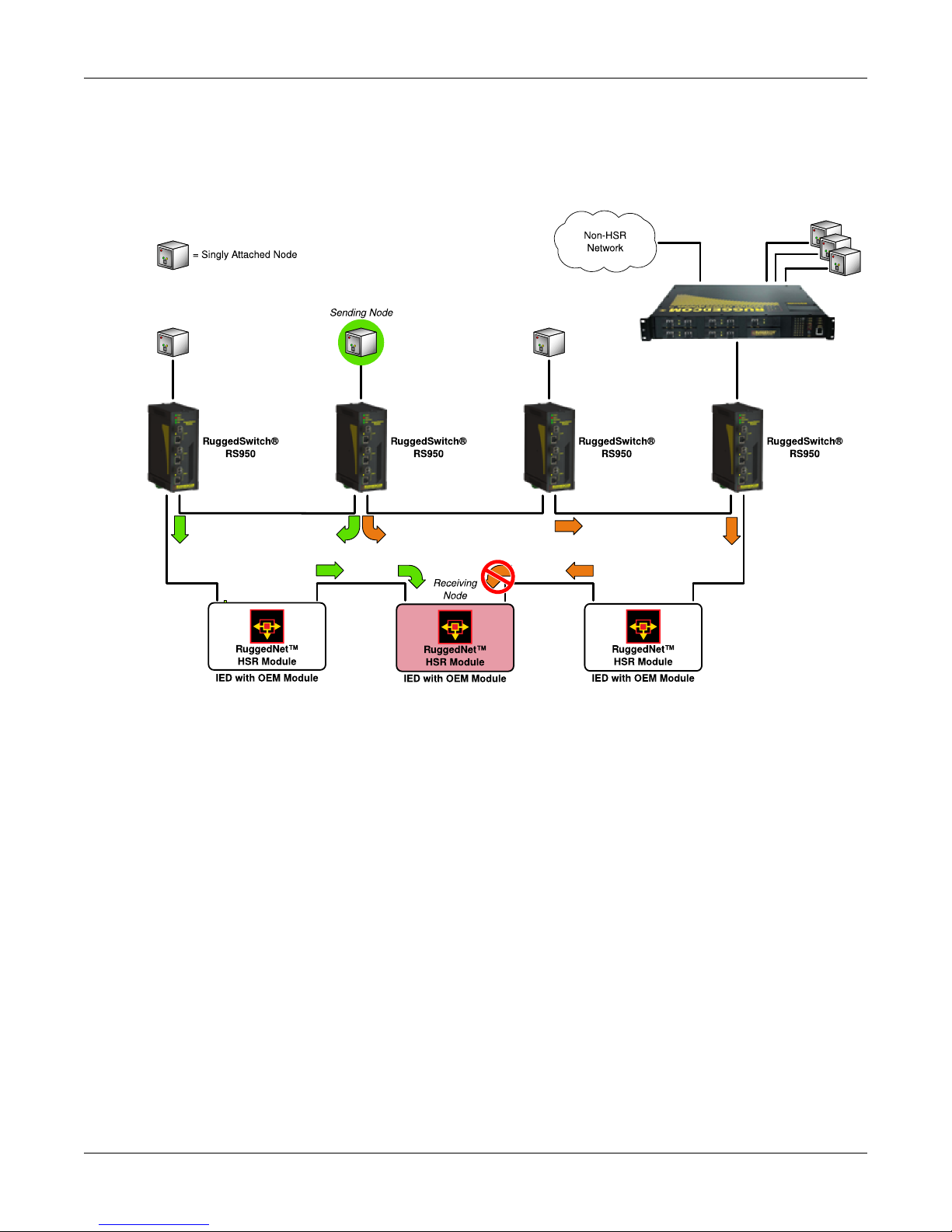
Figure 1.1. Typical HSR Ring Application
When the Sending Node communicates, the RS950G sends duplicate packets onto the network in
opposite directions. Using “cut-through” switching, packets are moved through the HSR network
to the receiving node with minimal latency. The receiving node removes duplicate packets from
the network. This example shows the use of both RS950G devices and the RuggedNet™ OEM
module.
RuggedCom® RuggedSwitch™ 9 RS950G Installation Guide Rev 100
 Loading...