

RuggedCom RuggedSwitch RS900 Family Installation Manual

RuggedSwitch®
RS900 Family
Industrially Hardened Ethernet Switches
Installation Guide
July 21, 2010
www.ruggedcom.com

RS900 Family Installation Guide
Copyright
COPYRIGHT © 2010 RuggedCom Inc. ALL RIGHTS RESERVED
Dissemination or reproduction of this document, or evaluation and communication of its
contents, is not authorized except where expressly permitted. Violations are liable for damages.
All rights reserved, particularly for the purposes of patent application or trademark registration.
This document contains proprietary information, which is protected by copyright. All rights are
reserved. No part of this document may be photocopied, reproduced or translated to another
language without the prior written consent of RuggedCom Inc.
Disclaimer of liability
We have checked the contents of this manual against the hardware and software described.
However, deviations from the description cannot be completely ruled out.
RuggedCom shall not be liable for any errors or omissions contained herein or for consequential
damages in connection with the furnishing, performance, or use of this material.
The information given in this document is reviewed regularly and any necessary corrections will
be included in subsequent editions. We appreciate any suggested improvements. We reserve
the right to make technical improvements without notice.
Registered Trademarks
®
RuggedServer™ is a trademark of RuggedCom Inc. RuggedSwitch
is a registered trademark
of RuggedCom Inc. Other designations in this manual might be trademarks whose use by third
parties for their own purposes would infringe the rights of the owner.
Contacting RuggedCom
Corporate Headquarters US Headquarters Europe Headquarters
RuggedCom Inc.
300 Applewood Crescent
Concord, Ontario
Canada, L4K 5C7
Tel: +1 905 856 5288
Fax: +1 905 856 1995
Toll-free: 1 888 264 0006
RuggedCom
1930 Harrison St., Suite 209
Hollywood, Florida
USA, 33020
Tel: +1 954 922 7938 ext. 103
Fax: +1 954 922 7984
Toll-free: 1 888 264 0006
RuggedCom
Unit 41, Aztec Centre,
Aztec West, Almondsbury, Bristol
United Kingdom BS32 4TD
Tel: +44 1454 203 404
Fax: +44 1454 203 403
Email: RuggedSales@RuggedCom.com
Technical Support
Toll Free (North America): 1 866 922 7975
International: +1 905 856 5288
Email: Support@RuggedCom.com
2010 RuggedCom Inc. 2 Rev107
Web: www.RuggedCom.com

RS900 Family Installation Guide
Federal Communications Commission Radio
Frequency Interference Statement
This equipment has been tested and found to comply with the limits for a Class A digital device pursuant to Part 15 of
the FCC Rules. These limits are designed t o provide reasonable protection against harmful interf erence when the
equipment is operated in a commercial environment. This equipment generates, uses and can radiate radio
frequency energy and, if not installed and used in accordance with the instruction manual, may cause harmful
interference to radio communications. Operation of this equipment in a residential area is likely to cause harmful
interference in which case the user wil l be required to correct the interference at his expense.
Caution
This product contains a laser system and is classified as a “CLASS 1 LASER PRODUCT”.
Use of controls or adjustments or performance of proc edures other than those specified herein may result in hazar dous
radiation exposure. This product contains no user-serv iceable parts. Attempted service by unauthorized personnel shall
render all warranties null and void.
Should this device require service see the “Warranty” section of this installation guide.
Important
This unit should be installed in a restricted access location where access can only be gained by service personnel or users
who have been instructed about the reasons for the rest rictions applied to the location and about any precautions that
shall be taken; and access is through the use of a too l or loc k and k ey, or o ther means of sec urity, and is controlle d by t he
authority responsible for the location.
2010 RuggedCom Inc. 3 Rev107

RS900 Family Installation Guide
Table of Contents
Federal Communications Commission Radio Frequency Interference Statement ...........3
Table of Contents..............................................................................................................4
Table of Figures................................................................................................................5
Table of Tables.................................................................................................................6
1 Product Overview......................................................................................................7
1.1 Functional Overview..........................................................................................7
1.2 RuggedSwitch®..................................................................................................8
1.3 RuggedWireless™ Family of Products..............................................................9
1.4 RuggedVDSL™ Family of Products................................................................11
1.5 RuggedServer™..............................................................................................13
1.6 Front Panel Description...................................................................................14
1.7 Bottom Panel Description................................................................................15
2 Installation...............................................................................................................16
2.1 Din Rail Mounting............................................................................................16
2.2 Power Supply Wiring and Grounding ..............................................................17
2.3 Console Port Wiring ........................................................................................21
3 Ethernet Ports .........................................................................................................22
3.1 Ethernet over VDSL Port.................................................................................22
3.2 Copper Ethernet Port ......................................................................................26
3.3 Fiber Optic Ethernet Port.................................................................................27
3.4 Wireless Ethernet Port ....................................................................................28
4 Serial Ports..............................................................................................................29
4.1 DB9 Serial Port................................................................................................29
4.2 RJ45 Serial Port..............................................................................................30
4.3 Fiber Serial Port ..............................................................................................31
4.4 RS485 Wiring..................................................................................................32
5 Transient Protection................................................................................................33
6 Technical Specifications..........................................................................................34
6.1 Operating Environment ...................................................................................34
6.2 Power Supply Specifications...........................................................................34
6.3 Failsafe Relay Specifications ..........................................................................34
6.4 Ethernet Ports Specifications..........................................................................35
6.5 Wireless Ethernet Port Specification...............................................................38
6.6 Serial Ports Specifications...............................................................................40
6.7 Mechanical Specifications...............................................................................41
7 Type Tests ..............................................................................................................42
7.1 IEC 61850-3 Type Tests .................................................................................42
7.2 IEEE 1613 Type Tests ....................................................................................43
7.3 IEC Environmental Type Tests........................................................................43
8 Agency Approvals ...................................................................................................44
9 Warranty..................................................................................................................44
2010 RuggedCom Inc. 4 Rev107

RS900 Family Installation Guide
Table of Figures
Figure 1 - Front Panel Description 14
Figure 2 - Bottom Panel Description 15
Figure 3 – DIN Rail Mounting 16
Figure 4 - Power Supply Inputs 17
Figure 5 - DC Power supply wiring and grounding diagram 18
Figure 6 - Failsafe Output Relay 19
Figure 7 - Dielectric Strength Testing 20
Figure 8 - RS232 Female DCE pin-out 21
Figure 9 - RJ11 port pin-out and LEDs 23
Figure 10 - RJ45 port pin-out and LEDs 26
Figure 11 - 100FX MTRJ connector 27
Figure 12 - 100FX ST connector 27
Figure 13 - 100FX SC connector 27
Figure 14 - 100FX LC connector 27
Figure 15: DB9 Female DCE Port pin-out 29
Figure 16: RJ45 Port pin-out 30
Figure 17: Fiber Serial Interface (ST Connector) 31
Figure 18: Conceptual recommended RS485 wiring diagram 32
Figure 19 - Mechanical Specifications 41
2010 RuggedCom Inc. 5 Rev107

RS900 Family Installation Guide
Table of Tables
Table 1 - Status LEDs.....................................................................................................14
Table 2 - RS232 Female DCE pin-out ............................................................................21
Table 3 - RJ11 port pin-out .............................................................................................23
Table 4 - RJ11 port LED description...............................................................................23
Table 5 - Typical Performance on 24 AWG PIC twisted-pair with Universal EoVDSL
ports ........................................................................................................................24
Table 6 - Typical Performance on 24 AWG PIC twisted-pair with Long-Reach EoVDSL
ports ........................................................................................................................24
Table 7 - RJ45 port pin-out .............................................................................................26
Table 8 - RJ45 port LED description...............................................................................26
Table 9: DB9 Female DCE Port pin-out..........................................................................29
Table 10: RJ45 Port pin-out............................................................................................30
Table 11 - Operating Environment..................................................................................34
Table 12 - Power Supply Specifications..........................................................................34
Table 13 - Failsafe Relay Specification ...........................................................................34
Table 14 - Failsafe Relay Isolation..................................................................................34
Table 15 – RJ11 Ethernet over VDSL Port Specifications..............................................35
Table 16 – RJ45 Ethernet Port Specifications ................................................................35
Table 17 - Fiber Optic Port Specifications.......................................................................36
Table 18 - Communication Standard Compliance ..........................................................37
Table 19 - Wireless Standards Supported......................................................................38
Table 20 - Radio Characteristics.....................................................................................38
Table 21 - Channel allocations for IEEE 802.11b/g........................................................39
Table 22: Copper Port Specification ...............................................................................40
Table 23: Fiber Optic Port Specification..........................................................................40
Table 24 - Mechanical Specifications..............................................................................41
Table 25 - IEC 61850-3 Type Tests................................................................................42
Table 26 - IEEE 1613 Type Tests...................................................................................43
Table 27 - Environmental Type Tests.............................................................................43
2010 RuggedCom Inc. 6 Rev107

RS900 Family Installation Guide
1 Product Overview
1.1 Functional Overview
The RuggedSwitch® RS900 family of Ethernet switches are environmentally hardened,
fully managed switches supporting a variety of Ethernet interfaces including copper,
fiber, wireless as well as Serial communications. The RS900 family’s superior
ruggedized design coupled with the RuggedSwitch Operating System (ROS™) provides
improved system reliability and advanced networking features making it ideally suited for
creating Ethernet networks for mission-critical, real-time, control applications.
RS900 Family Common Product Features
Operating temperature: -40° to 85°C (no fans)
Fully integrated power supply
Power supply options: 12, 24, 48 or 60 VDC, and Universal HI (88-300VDC or
84-264VAC)
Failsafe output relay for critical failure or error alarming
Industry standard fiber optical connectors: LC, SC, ST, MTRJ
Multimode and Singlemode optical transceivers
Long haul optics allow distances up to 90 km
Advanced layer-2 switching functions including Flow-Control, Link Aggregation,
MAC Bridges, Rapid Spanning Tree, Message Prioritization, VLANs and Port
Based Network Access Control
2010 RuggedCom Inc. 7 Rev107
RS900 Family Installation Guide
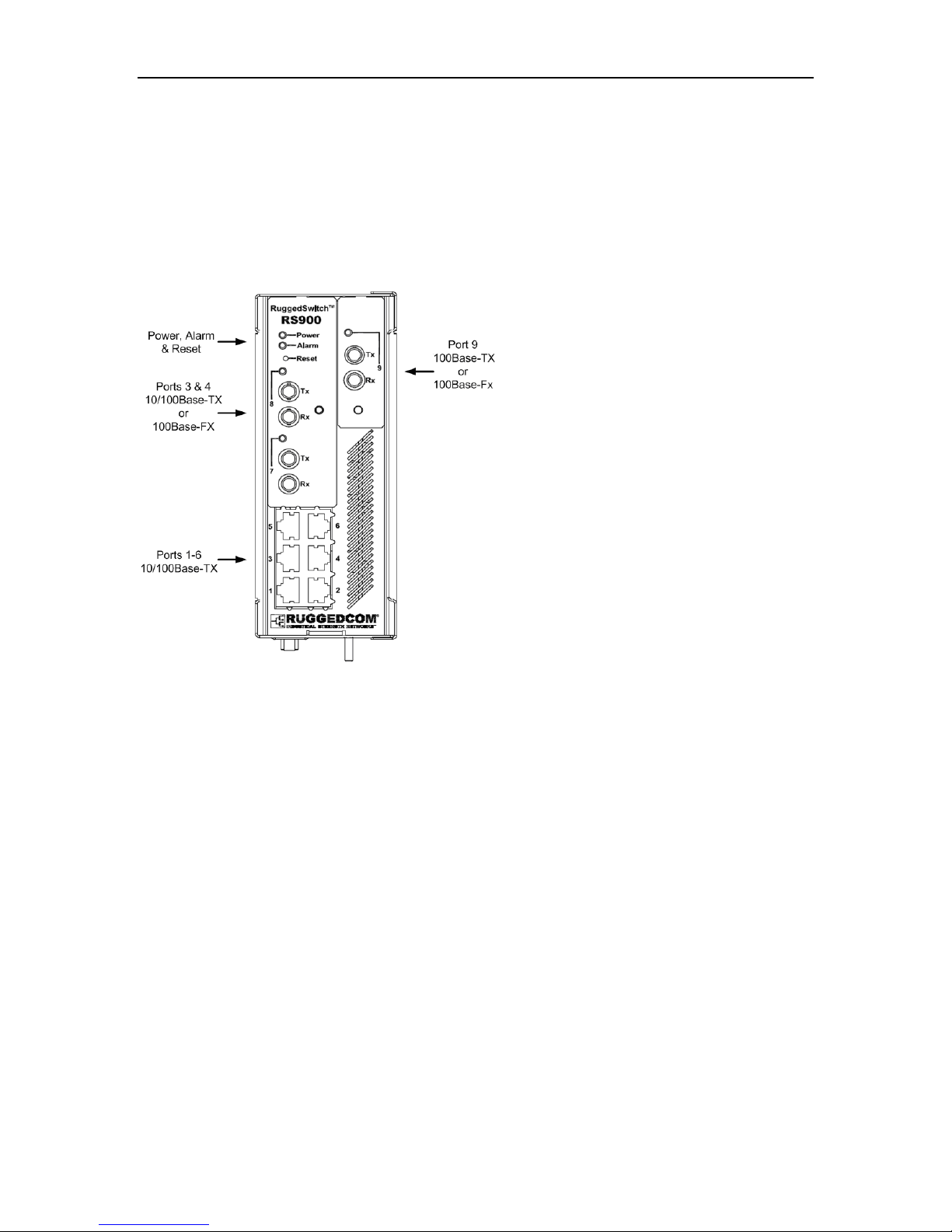
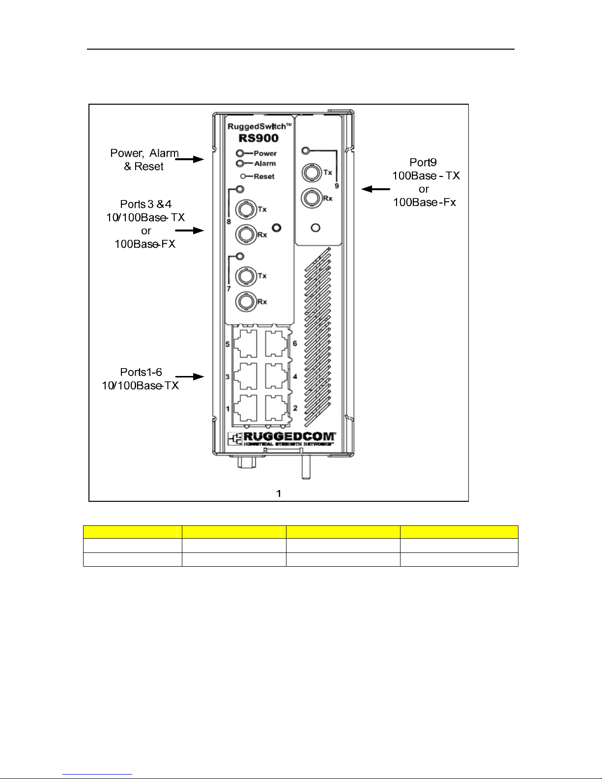
1.2 RuggedSwitch®
RS900
9 Port Fiber Optic Ethernet Switch
Up to 9 fast Ethernet ports
Copper and fiber options
2010 RuggedCom Inc. 8 Rev107
RS900 Family Installation Guide
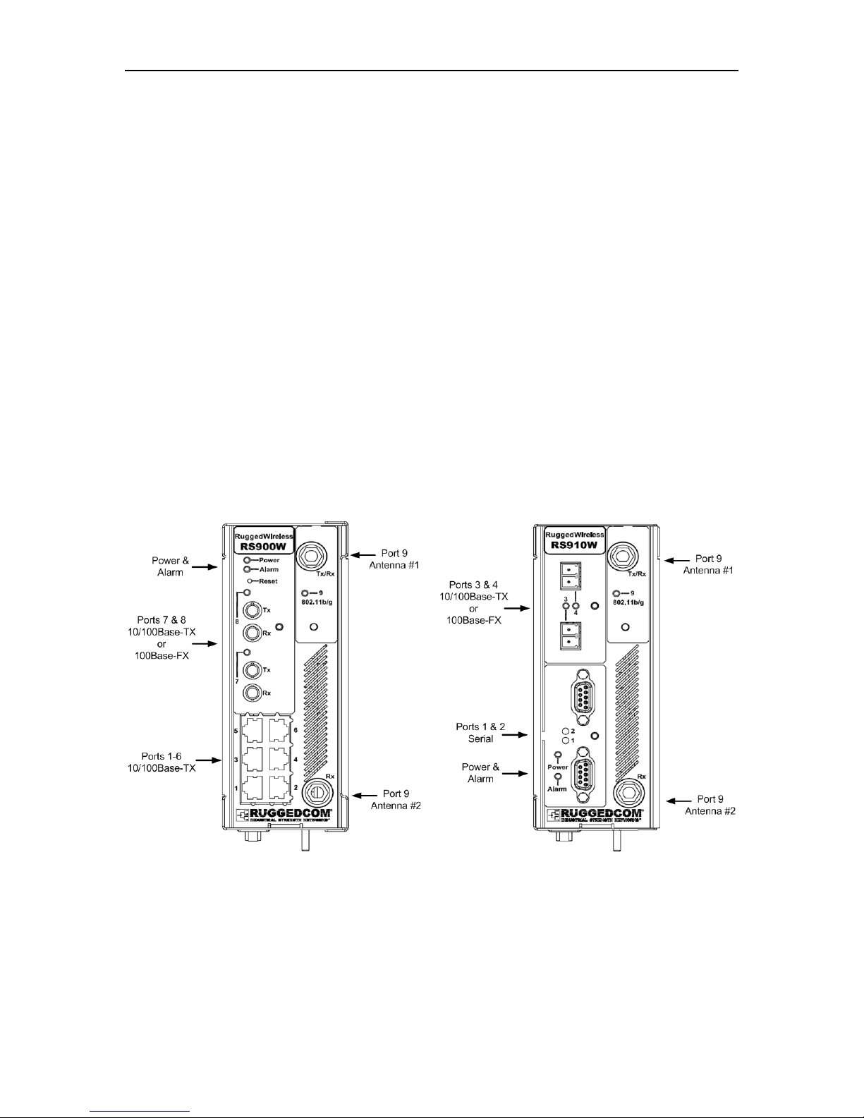
1.3 RuggedWireless™ Family of Products
Wireless Port Characteristics
Configurable as an access, client, or bridge device
IEEE 802.11b/g Wireless Access Point with data rates up to 54 Mbps
WPA (Wi-Fi Protected Access) with TKIP for enhanced security and encryption
WPA2 / 802.11i with CCMP for robust security and encryption
IEEE 802.1X / RADIUS using EAP-PEAP for secure "enterprise class"
authentication configuration
Pre-shared Key Mode (PSK) for "personal" mode authentication configuration
RS900W
Wireless Ethernet with integrated 8-Port
Switch
1 Wireless interface
Up to 8 fast Ethernet ports
Copper and fiber options
RS910W
Wireless Serial Device Server with 2
Serial and/or 2 Ethernet Ports
1 Wireless interface
2 RS485/RS422/RS232 Serial
ports (DB9 or RJ45); Serial Fiber
interface (ST) available
2 Optional Ethernet ports
2010 RuggedCom Inc. 9 Rev107
RS900 Family Installation Guide
A
A
A
RS920W
Wireless Serial Device Server with 2
Serial Ports and 1 Ethernet over VDSL
Interface
1 Wireless interface
1 EoVDSL interface
2 RS485/RS422/RS232 Serial
ports (DB9 or RJ45); Serial Fiber
interface (ST) available
Port 9
ntenna #1
Port 7
Ethernet
over VDSL
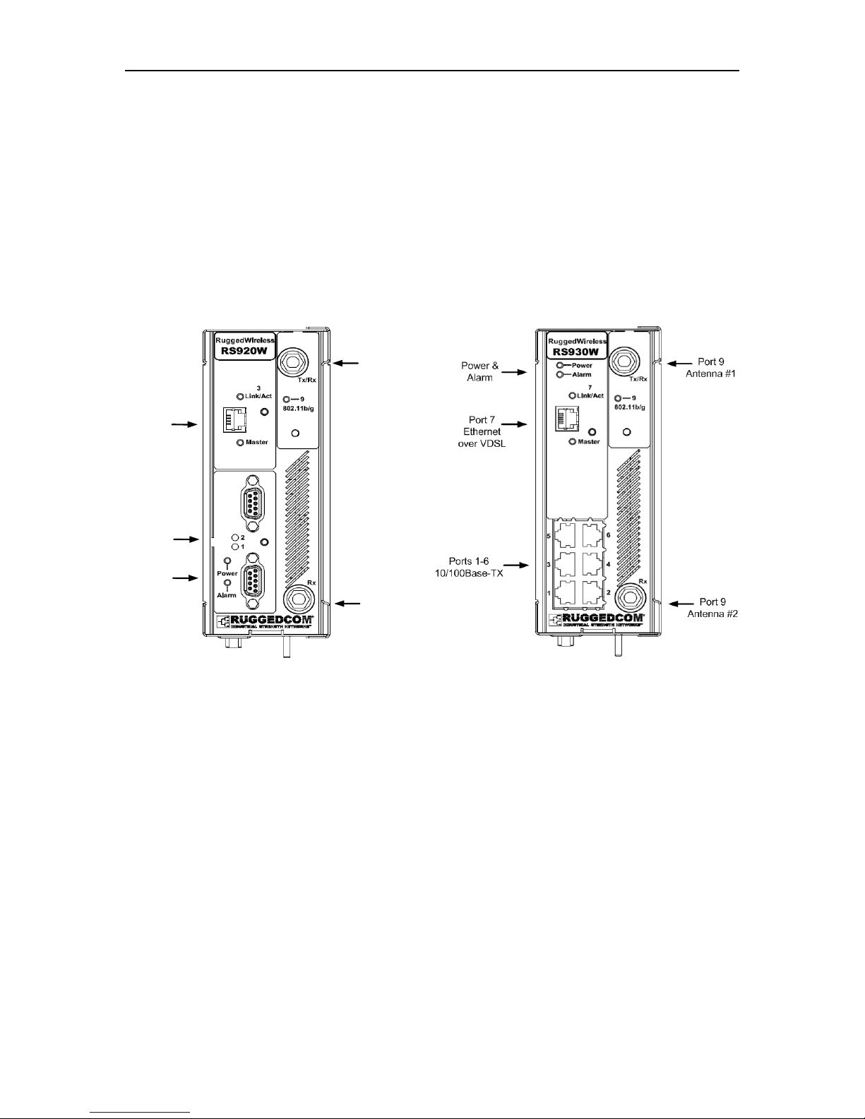
RS930W
Wireless Ethernet with Integrated 6-Port
Switch and 1 Ethernet over VDSL
Interface
1 Wireless interface
1 EoVDSL interface
6 fast Ethernet ports
Ports 1 &
Serial
Power &
larm
2
Port 9
ntenna #2
2010 RuggedCom Inc. 10 Rev107
RS900 Family Installation Guide
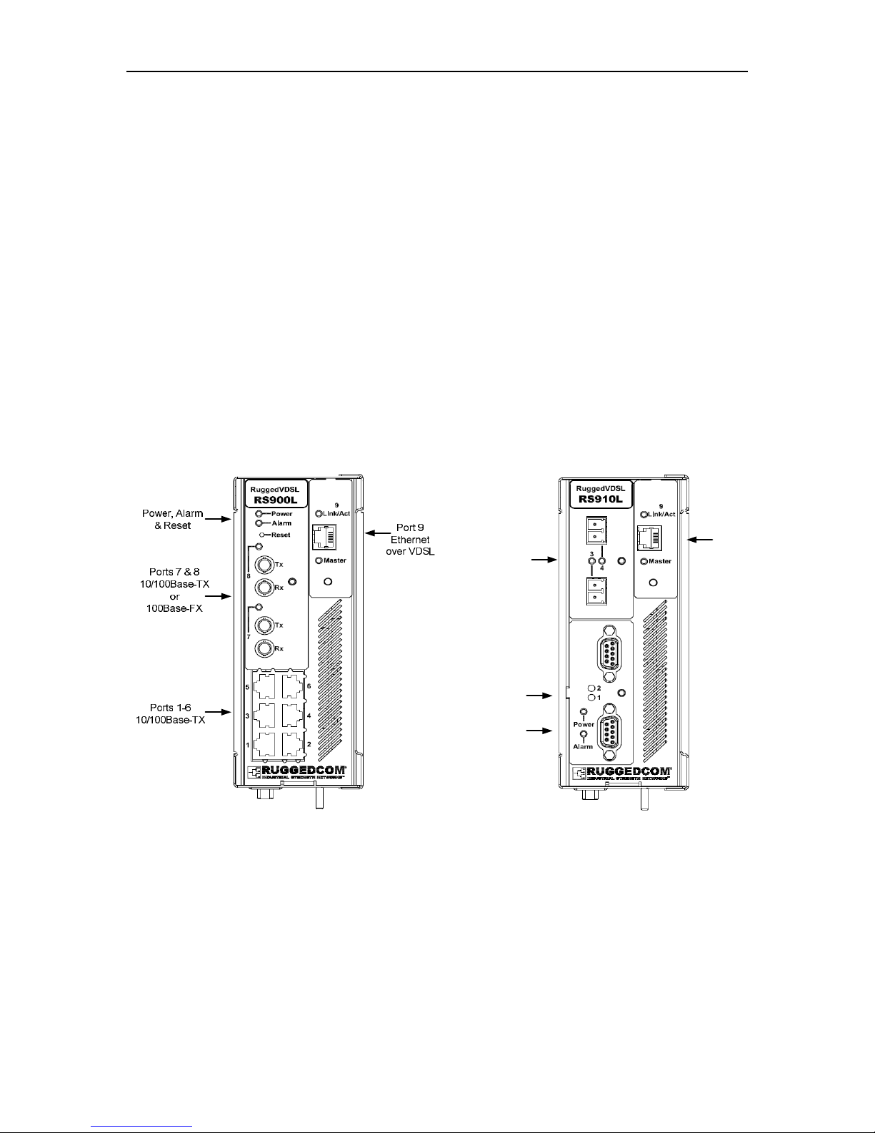
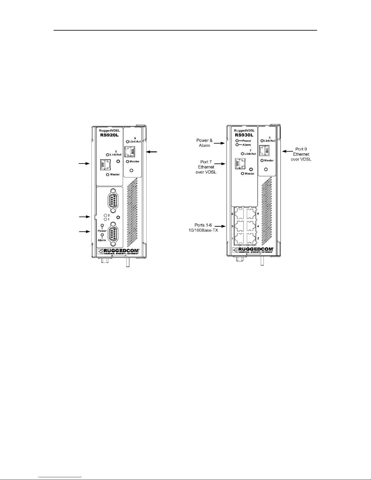
1.4 RuggedVDSL™ Family of Products
EoVDSL Port Characteristics
Symmetric data rates up to 35 Mbps with distances up to 2.5 km
Asymmetric data rates up to 40 Mbps with distances up to 5 km
Automatically selects fastest data rate based on distance and quality of cable
Manual speed configuration available
RS900L
Ethernet over VDSL with integrated 8-Port
Switch
1 EoVDSL interface
Up to 8 fast Ethernet ports
Copper and fiber options
RS910L
Ethernet over VDSL with 2 Serial and/or
2 Ethernet Ports
1 EoVDSL interface
2 RS485/RS422/RS232 Serial ports
(DB9 or RJ45); Serial Fiber interface
(ST) available
2 Optional Ethernet ports
Ports 3 & 4
10/100Base-TX
or
100Base-FX
Ports 1 & 2
Serial
Power &
Alarm
Port 9
Ethernet
over VDSL
2010 RuggedCom Inc. 11 Rev107
RS900 Family Installation Guide
RS920L
Dual Ethernet over VDSL interfaces with
integrated Dual Port Serial Server
2 EoVDSL interfaces
2 RS485/RS422/RS232 Serial
ports (DB9 or RJ45); Serial Fiber
interface (ST) available
Port 9
Ethernet
Port 3
Ethernet
over VDSL
over VDSL
RS930L
Dual Ethernet over VDSL interfaces with
Integrated 6-Port Switch
2 EoVDSL interfaces
6 fast Ethernet ports
Ports 1 & 2
Serial
Power &
Alarm
2010 RuggedCom Inc. 12 Rev107
RS900 Family Installation Guide
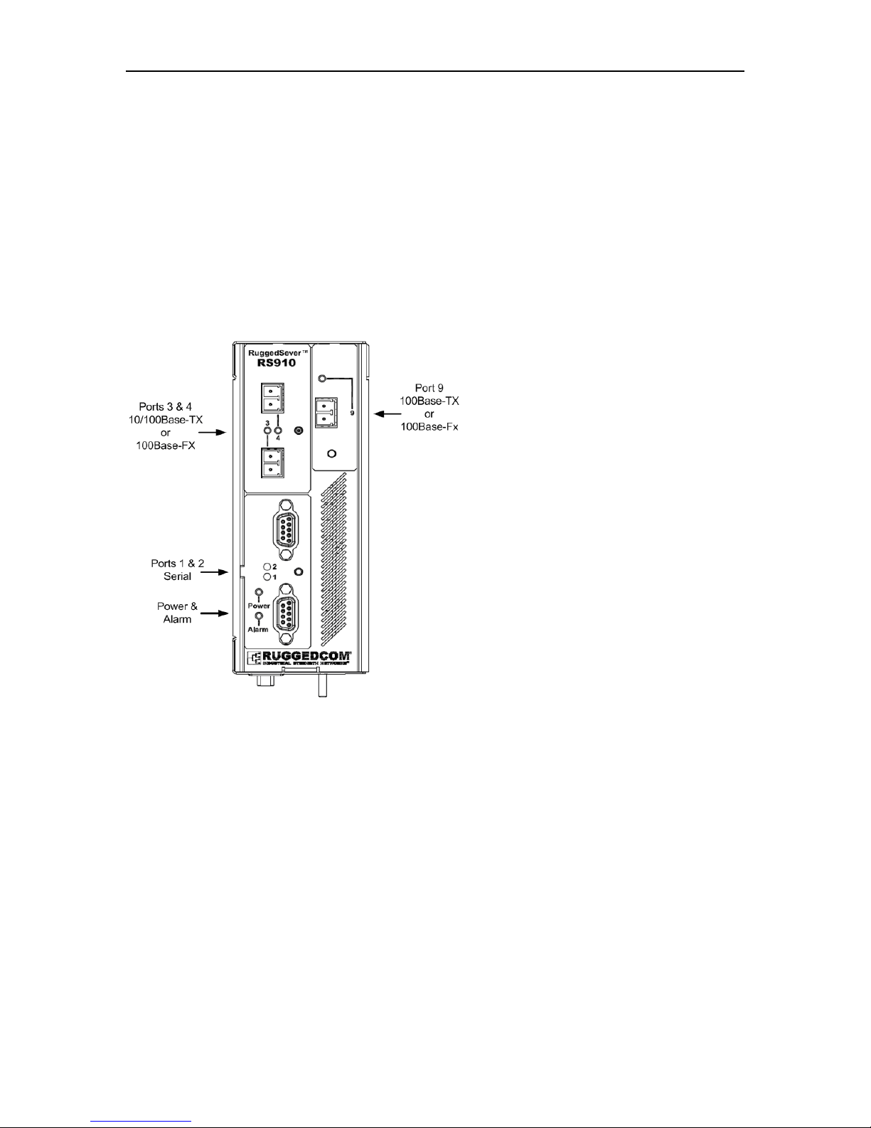
1.5 RuggedServer™
RS910
2-Port Serial Device Server with up to 3
Ethernet Ports
2 RS485/RS422/RS232 Serial ports (DB9
or RJ45); Serial Fiber interface (ST)
available
Up to 3 fast Ethernet ports
Copper and fiber options
2010 RuggedCom Inc. 13 Rev107
RS900 Family Installation Guide
1.6 Front Panel Description
Figure 1 - Front Panel Description
Status LED Colour Activity Comments
Power LED Green Solid Power On
Alarm LED Red Solid Alarm condition exists
Table 1 - Status LEDs
2010 RuggedCom Inc. 14 Rev107
 Loading...