

Page 1
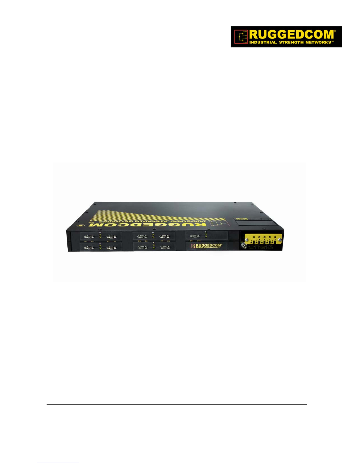
RuggedSwitch™ M2200
MIL-STD 9-Port Modular Managed
Gigabit Ethernet Switch
Installation Guide
www.RuggedCom.com
RuggedCom Inc. I 30 Whitmore Road, Woodbridge, Ontario, Canada L4L 7Z4
Tel: 905-856-5288 I Fax: 905-856-1995 I Toll Free: 1-888-264-0006
Page 2

Federal Communications Commission
Radio Frequency Interference Statement
This equipment has been tested and found to comply with the limits for a Class A digital device
pursuant to Part 15 of the FCC Rules. These limits are designed to provide reasonable protection
against harmful interference when the equipment is operated in a commercial environment. This
equipment generates, uses and can radiate radio frequency energy and, if not installed and used in
accordance with the instruction manual, may cause harmful interference to radio communications.
Operation of this equipment in a residential area is likely to cause harmful interference in which
case the user will be required to correct the interference at his expense.
CAUTION
This product contains a laser system and is classified as a “CLASS 1 LASER PRODUCT”
CAUTION
Use of controls or adjustments or performance of procedures other than those specified herein may result in
hazardous radiation exposure. This product contains no user serviceable parts. Attempted service by
unauthorized personnel shall render all warranties null and void.
Changes or modifications not expressly approved by RuggedCom Inc. could void the user’s authority to operate
the equipment.
Should this device require service see the “Warranty and Service” section of this guide.
IMPORTANT
The RX1000 family of products should be installed in a restricted access location where access can only be
gained by service personnel or users who have been instructed about the reasons for the restrictions applied to the
location and about any precautions that shall be taken; and access is through the use of a tool or lock and key, or
other means of security, and is controlled by the authority responsible for the location.
Trademarks:
Ethernet is a trademark of Xerox Corporation
RuggedRouter and RuggedRated, are trademarks of RuggedCom® Inc.
2
© 2008 RuggedCom Inc. All rights reserved Rev105
Page 3

Table of Contents
1 Table of Figures ...................................................................................................................... 4
2 Table of Tables........................................................................................................................ 4
3 Product Overview.................................................................................................................... 5
3.1 Functional Overview & Feature Highlights........................................................ 5
3.2 Ethernet Panel Description ................................................................................. 7
3.2.1 Fiber Optical Transceiver Orientation and Connection.............................. 8
3.3 Display Panel Description................................................................................... 9
4 Installation..............................................................................................................................11
4.1 Panel Mounting................................................................................................. 11
4.2 Power Supply Wiring and Grounding............................................................... 12
4.2.1 AC Power Supply Wiring Examples ........................................................ 14
4.2.2 DC Power Supply Wiring Examples ........................................................ 15
4.2.3 Dual Power Supplies – DC and AC Inputs............................................... 16
4.3 Dielectric Strength (HIPOT) Testing................................................................ 17
4.4 Failsafe Alarm Relay Wiring and Specifications.............................................. 18
4.5 Console Port Wiring ......................................................................................... 19
4.6 Twisted-Pair Data Ports.................................................................................... 20
4.6.1 Micro-D Twisted-Pair Data Ports............................................................. 20
4.6.2 Protection on Twisted-Pair Data Ports...................................................... 21
4.7 Gigabit Ethernet 1000Base-Tx Cabling Recommendations............................. 22
5 Technical Specifications.........................................................................................................23
5.1 Power Supply Specifications ............................................................................23
5.2 Failsafe Relay Specifications............................................................................ 23
5.3 Networking Standards Supported..................................................................... 24
5.4 Twisted-Pair Port Specifications....................................................................... 24
5.5 Fiber Optical Specifications.............................................................................. 25
5.5.1 Gigabit Ethernet (1000Mbps) Modules.................................................... 25
5.6 Type Test Specifications................................................................................... 26
5.7 Operating Environment..................................................................................... 27
5.8 Mechanical Specifications................................................................................ 28
6 Agency Approvals ..................................................................................................................29
7 Warranty.................................................................................................................................29
© 2008 RuggedCom Inc. All rights reserved Rev105
3
Page 4

1 Table of Figures
Figure 1: Ethernet panel LED description........................................................................................ 7
Figure 2: 1000BaseX LC connector................................................................................................ 8
Figure 3: M2000 Series LED Display Panel.................................................................................... 9
Figure 4: M2200 Panel Mounting Diagram.....................................................................................11
Figure 5: M2000 Series Philips Screw Terminal Block....................................................................12
Figure 6: AC Power supply wiring examples...................................................................................14
Figure 7: DC Power supply wiring examples..................................................................................15
Figure 8: DC And AC power supply wiring examples.....................................................................16
Figure 9: Dielectric Strength (HIPOT) Testing.................................................................................17
Figure 10: Failsafe Alarm Relay Wiring...........................................................................................18
Figure 11: Console port location on display board.........................................................................19
Figure 12: M2200 Console cable...................................................................................................19
Figure 13: Micro-D port pin configuration........................................................................................20
Figure 14: Mechanical Dimensions.................................................................................................28
2 Table of Tables
Table 1: LED Display – Device status LED behavior definition....................................................... 9
Table 2: LED Display Description...................................................................................................10
Table 3: M2200 Power terminal block connection description.........................................................13
Table 4: RS232 over RJ45 console cable pin-out..........................................................................19
Table 5: Cabling categories and 1000BaseTx compliance defined................................................22
© 2008 RuggedCom Inc. All rights reserved Rev105
4
Page 5

3 Product Overview
3.1 Functional Overview & Feature Highlights
The RuggedSwitch M2200 is a MIL-STD hardened, fully managed, modular Gigabit Ethernet
switch specifically designed to operate reliably in harsh environments. The M2200’s superior
ruggedized hardware design coupled with the embedded Rugged Operating System (ROS™)
provides improved system reliability, and advanced cyber security and networking features making
it ideal for creating secure mission critical real-time control applications, and for aggregating
Ethernet switches onto a Gigabit backbone.
The M2200's modular flexibility offers 1000BaseX fiber (LC connectors) and 10/100/1000BaseTX
copper port (Micro-D connectors) combinations. The M2200 is packaged in a rugged galvanized
steel enclosure and provides MIL-901D shock and vibration immunity. The M2200 is highly
versatile and suitable for many applications within a “harsh” environment.
Ethernet Ports
• Up to 9-Gigabit Ethernet ports - copper and/or fiber
• 2 port modules for tremendous flexibility
• Supports multimode and singlemode fiber
• Non-blocking, store and forward switching
• Supports LC connectors for fiber, Mirco-D connectors for copper
RuggedRated™ for Reliability in Harsh Environments
• Immunity to EMI and heavy electrical surges
• Zero-Packet-Loss™ Technology
• -40 to +85°C operating temperature (no fans)
• Conformal coated printed circuit boards
• 18 AWG galvanized steel enclosure
MIL-STD Ratings
• MIL-STD 901D – Shock (Hard Mounted)
• MIL-STD 167 – Vibration
• MIL-STD 461 – EMI
• MIL-STD 1399 – Magnetic Field (DC Magnetic Exposure)
• MIL-STD 810 – Temperature and Humidity
Universal Power Supply Options
© 2008 RuggedCom Inc. All rights reserved Rev105
5
Page 6

• Fully integrated, dual-redundant (optional) power supplies
• Universal high-voltage range: 88-300VDC or 85-264VAC
• Popular low voltage DC ranges: 12, 24 or 48 VDC
• Terminal blocks for reliable maintenance free connections
• CSA/UL 60950 safety approved to +85°C
Simple Plug and Play Operation
• Automatic learning of up to 8192 MAC addresses
• Auto-negotiation on all 10/100/1000BaseTX ports
• Auto-MDI/MDIX (crossover) on all 10/100BaseTX ports
• LED indicators for link, activity and speed
Rugged Operating System (ROS™) Advanced Network Management
• Enhanced Rapid Spanning Tree (eRSTP™)
• Quality of Service (802.1p) for real-time traffic
• Port rate limiting: 128kbps - 8Mbps
• VLAN (802.1q) with double tagging
• IGMP Snooping for multicast filtering
• Port configuration, status, statistics, mirroring, security
• Loss of link management on fiber ports
• Web-based, Telnet, CLI management interfaces
• SNMP v2 and RMON
• Rich set of diagnostics with logging and alarms
© 2008 RuggedCom Inc. All rights reserved Rev105
6
Page 7
3.2 Ethernet Panel Description
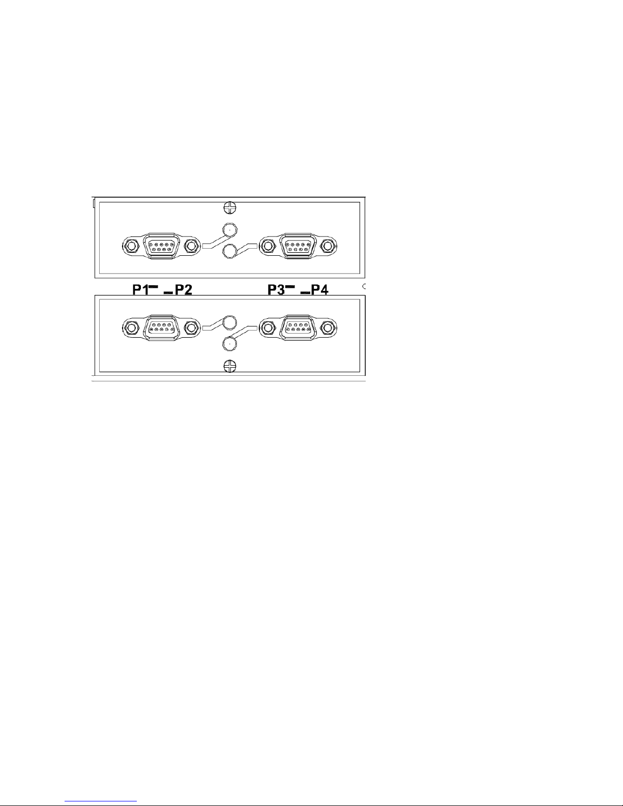
Each Ethernet module is equipped with two LEDs that indicate link/activity status information. The
LED will be solid for ports with link, and will blink for activity. The diagram in Figure 1 highlights the
port and the associated link/activity LED.
Figure 1: Ethernet panel LED description
© 2008 RuggedCom Inc. All rights reserved Rev105
7
Page 8
3.2.1 Fiber Optical Transceiver Orientation and Connection
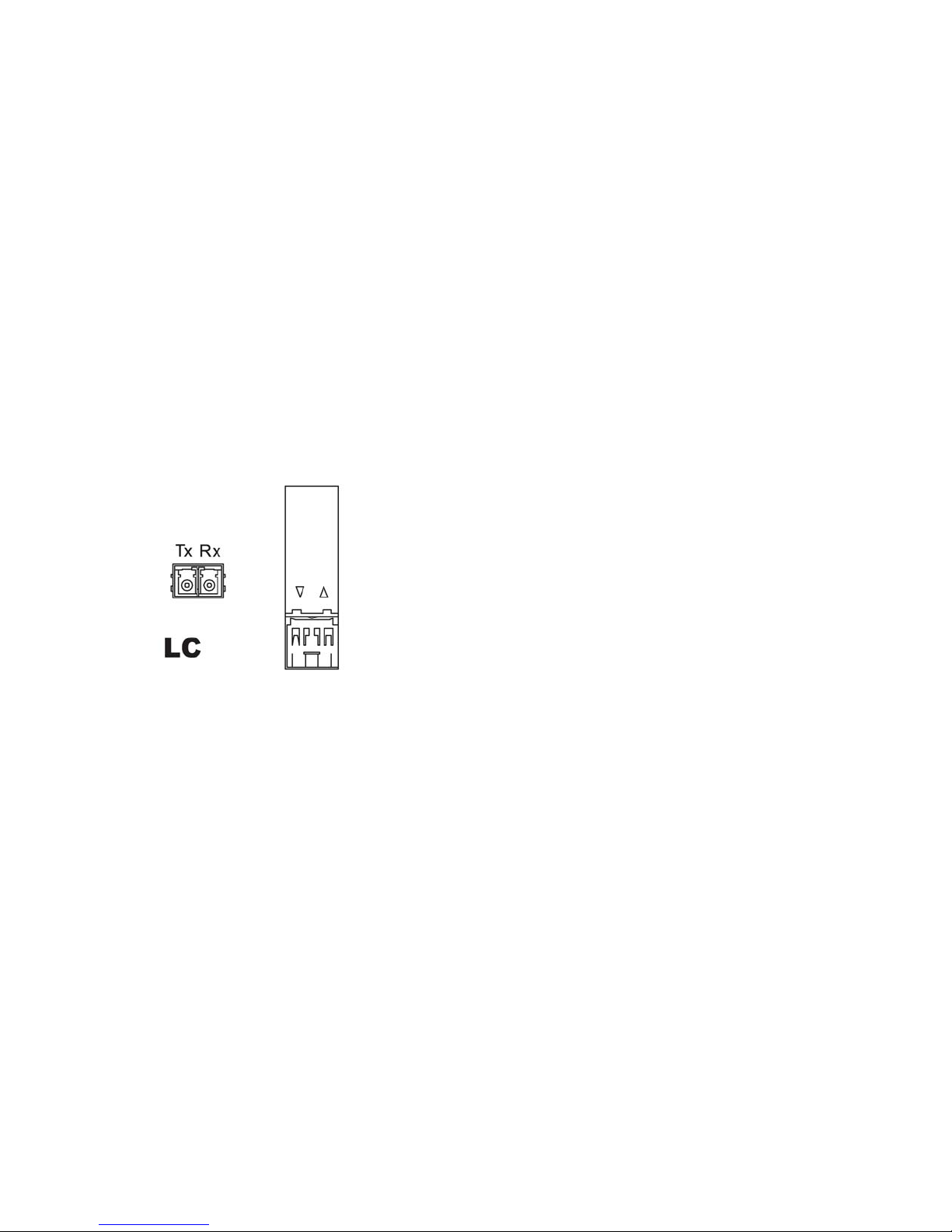
Depending on the order code of the product, the M2000 series products can be equipped with
different types of fiber optic ports. The Transmit (TX) and Receive (RX) connections of each port
must be properly connected and matched for proper link and operation. Modules populated on the
top row of the device typically have locking mechanisms or tabs towards the top of the unit.
Modules located on the bottom row of the device have locking mechanisms or tabs towards the
bottom of the device.
The drawings in the following figures show each fiber optical connector style with a side and top
view to allow the user to identify the proper cable connection orientation. If modules are populated
on the bottom row of the device, the transceiver orientation will be reversed (i.e. RX and TX will be
reversed).
Figure 2: 1000BaseX LC connector
8
© 2008 RuggedCom Inc. All rights reserved Rev105
Page 9
3.3 Display Panel Description
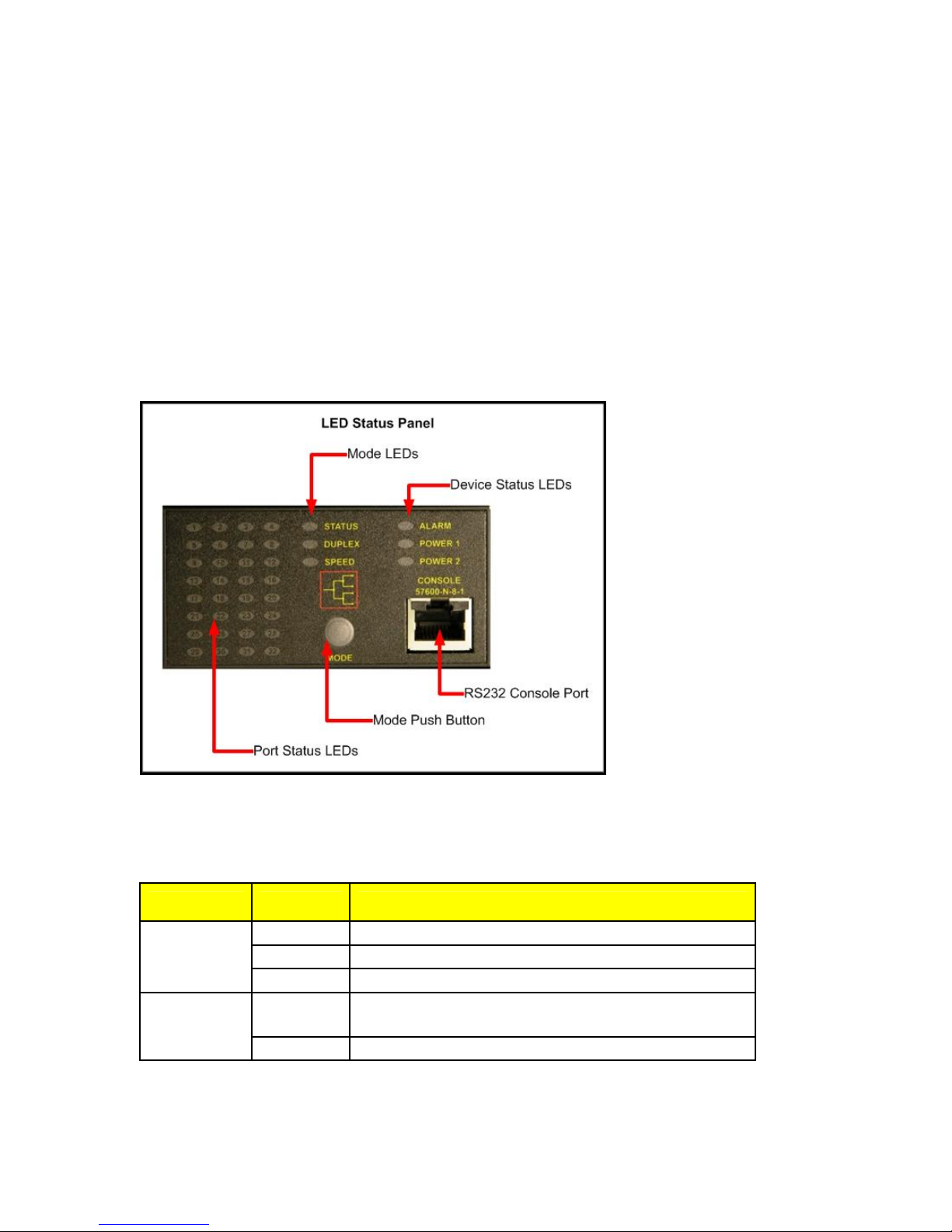
The M2000 series products are equipped with a versatile display panel, shown in Figure 3, which is
designed to provide quick status information for each port, as well as the entire device to allow for
simple diagnostics and troubleshooting. It features:
• RS232 console port for ‘out of band’ console access and configuration
• Power supply and Alarm status indicators
• Convenient port status indicators conveying Link-Activity, Duplex, or Speed via push-
button control.
• System reset via push-button if held for 5 seconds
Figure 3: M2000 Series LED Display Panel
Device status LEDs exist to provide a quick visual indicator to operators for operational status of
the unit.
Table 1 defines the possible LED colours and the corresponding description.
LED Colour Description
Green Power supply operating normal
PS1 / PS2
Red Power supply failure
Off No power supply installed
Red Alarm exist – login to web management interface to
Alarm
Off No alarms exist
Table 1: LED Display – Device status LED behavior definition
© 2008 RuggedCom Inc. All rights reserved Rev105
determine alarm code
9
Page 10
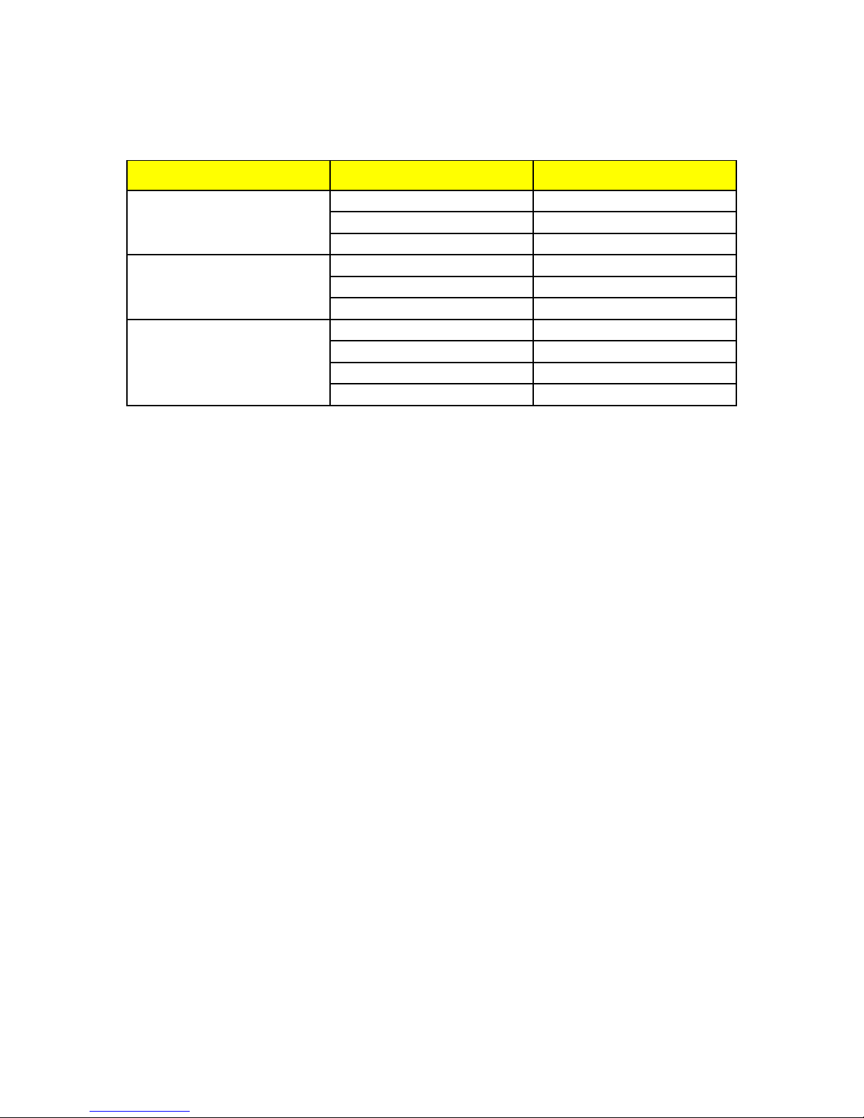
The port-based LEDs can be cycled between three display modes: Status, Duplex, and Speed.
Pushing the mode button causes the display mode to be cycled.
Mode Colour Description
Green (Solid) Link
Status
Green (Blinking) Activity
Off No link
Green (Solid) Full-Duplex operation
Duplex
Orange (Solid) Half-Duplex operation
Off No link
Green (Blinking) 1000Mb/s
Speed
Green (Solid) 100Mb/s
Orange (Solid) 10Mb/s
Off No link
Table 2: LED Display Description
© 2008 RuggedCom Inc. All rights reserved Rev105
10
Page 11
4 Installation
4.1 Panel Mounting
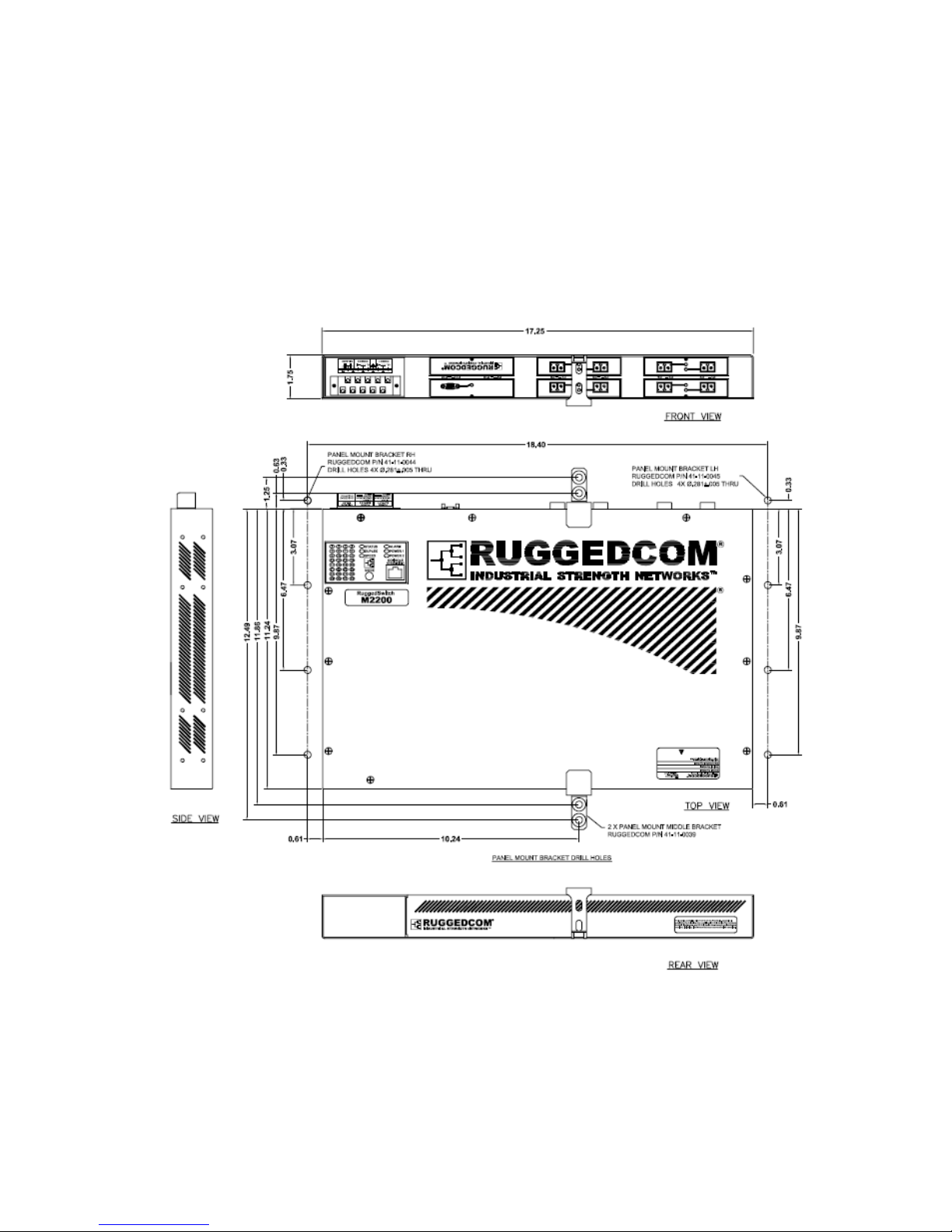
The M2000 series products can be ordered with Panel mount chassis. This option involves the use
of the panel adapters to be mounted on each side of the chassis enclosure. See Figure 4 for a
Panel mount diagram.
Figure 4: M2200 Panel Mounting Diagram
© 2008 RuggedCom Inc. All rights reserved Rev105
11
Page 12
4.2 Power Supply Wiring and Grounding
Philips Screw Terminal without CoverPhilips Screw Terminal with Cover
Safety Cover
Safety Cover
Screws
Chassis Ground
Connection
Surge / Chassis
Ground Jumper
Terminal
Figure 5: M2000 Series Philips Screw Terminal Block
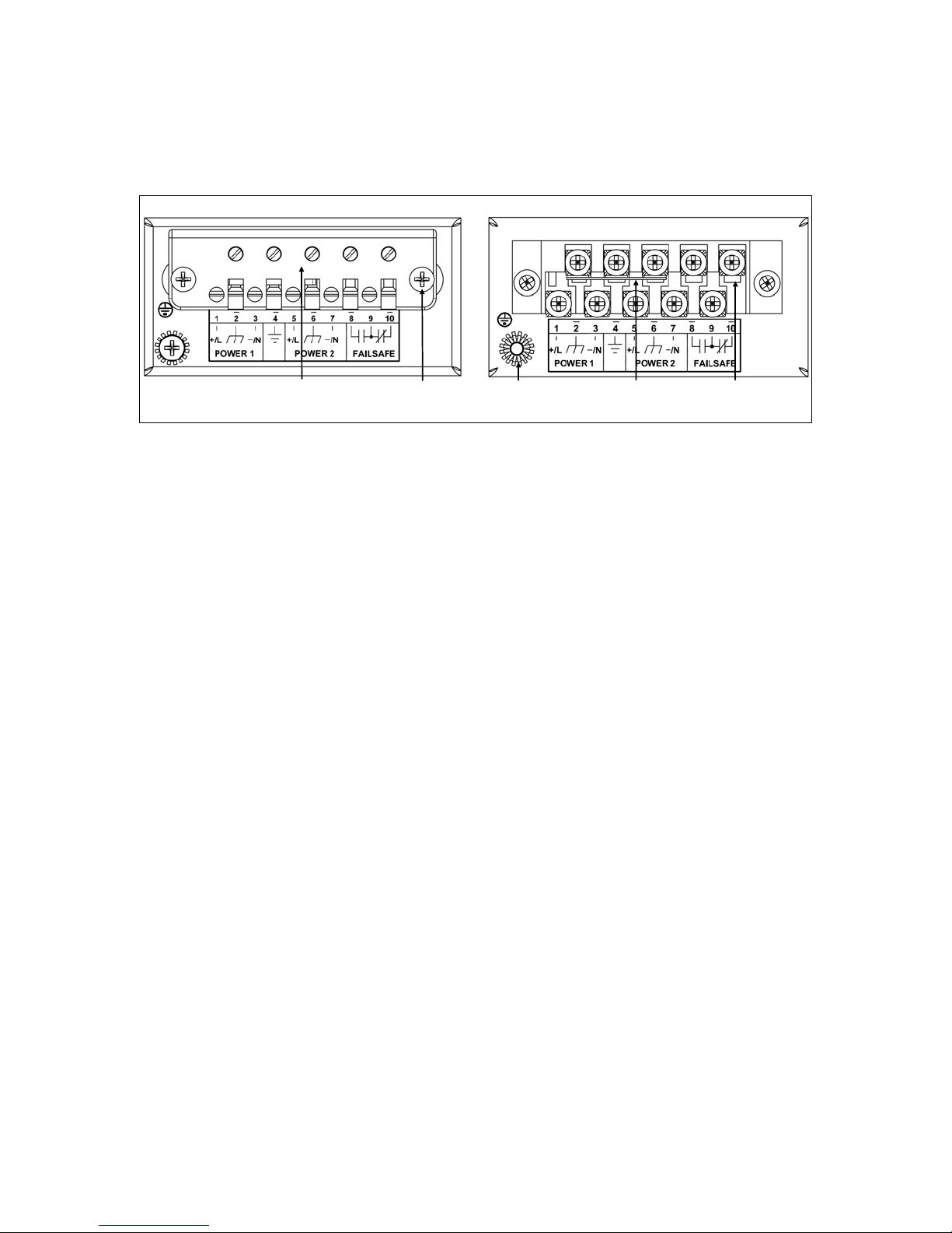
The M2000 Family supports dual redundant power supplies – “Power Supply 1 (PS1)” and “Power
Supply 2 (PS2)”. The connections for PS1, PS2 and the fail-safe relay are located on the terminal
block as shown in Figure 5.
The M2000 Family is equipped with a Philips Screw Terminal Block. The Philips Screw Terminal
Block has Philips screws with a compression plate allowing either bare wire connections or
crimped terminal lugs. RuggedCom recommend the use of #6 size ring lugs to ensure secure,
reliable connections under severe shock or vibration. The terminal block has a safety cover which
must be removed via two Phillips screws before connecting any wires. The safety cover must be
re-attached after wiring to ensure personnel safety. Refer to Table 3 below for a description of each
terminal as well as sections 4.2.1 through 4.2.3 for wiring examples.
© 2008 RuggedCom Inc. All rights reserved Rev105
12
Page 13

Terminal # Description Usage
PS1 Live / + is connected to the positive (+) terminal if the
1 PS1 Live / +
power source is DC or to the (Live) terminal if the power
source is AC.
PS1 Surge Ground is connected to the Chassis Ground via
a jumper on the terminal block. Surge Ground is used as the
2 PS1 Surge Ground
ground conductor for all surge and transient suppression
circuitry. NOTE: Surge Ground must be disconnected from
Chassis Ground during HIPOT (dielectric strength) testing.
PS1 Neutral / - is connected to the negative (-) terminal if
3 PS1 Neutral / -
the power source is DC or to the (Neutral) terminal if the
power source is AC.
Chassis Ground is connected to the Safety Ground
4 Chassis Ground
terminal for AC inputs or the equipment ground bus for DC
inputs. Chassis ground connects to both power supply surge
grounds via a removable jumper.
PS2 Live / + is connected to the positive (+) terminal if the
5 PS2 Live / +
power source is DC or to the (Live) terminal if the power
source is AC.
PS2 Surge Ground is connected to the Chassis Ground via
a jumper on the terminal block. Surge Ground is used as the
6 PS2 Surge Ground
ground conductor for all surge and transient suppression
circuitry. NOTE: Surge Ground must be disconnected from
Chassis Ground during HIPOT (dielectric strength) testing.
PS2 Neutral / - is connected to the negative (-) terminal if
7 PS2 Neutral / -
the power source is DC or to the (Neutral) terminal if the
power source is AC.
8 Relay NO Contact Normally open, failsafe relay contact.
9 Relay Common Failsafe relay common contact.
10 Relay NC Contact Normally closed, failsafe relay contact.
Table 3: M2200 Power terminal block connection description
© 2008 RuggedCom Inc. All rights reserved Rev105
13
Page 14
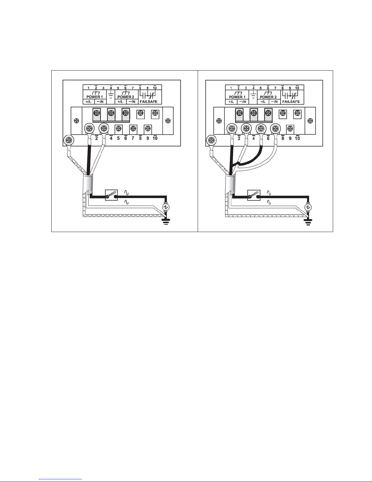
4.2.1 AC Power Supply Wiring Examples
Figure 6: AC Power supply wiring examples
NOTES:
1. 100-240VAC rated equipment: A 250VAC appropriately rated circuit breaker must be
installed within 3m of unit.
2. Equipment must be installed according to the applicable country wiring codes.
3. When equipped with two HI voltage power supplies, independent AC sources can be used
to power the product for greater redundancy.
© 2008 RuggedCom Inc. All rights reserved Rev105
14
Page 15
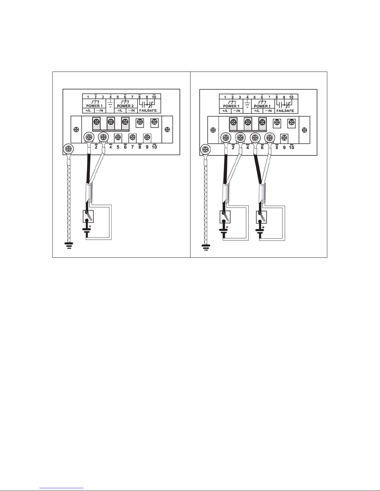
4.2.2 DC Power Supply Wiring Examples
Figure 7: DC Power supply wiring examples
NOTES:
1. 88-300VDC rated equipment: A 300VDC appropriately rated circuit breaker must be
installed within 3m of unit.
2. A circuit breaker is not required for 12, 24 or 48 VDC rated power supplies.
3. For dual DC power supplies, Separate circuit breakers must be installed and
separately identified.
4. Equipment must be installed according to the applicable country wiring codes.
© 2008 RuggedCom Inc. All rights reserved Rev105
15
Page 16
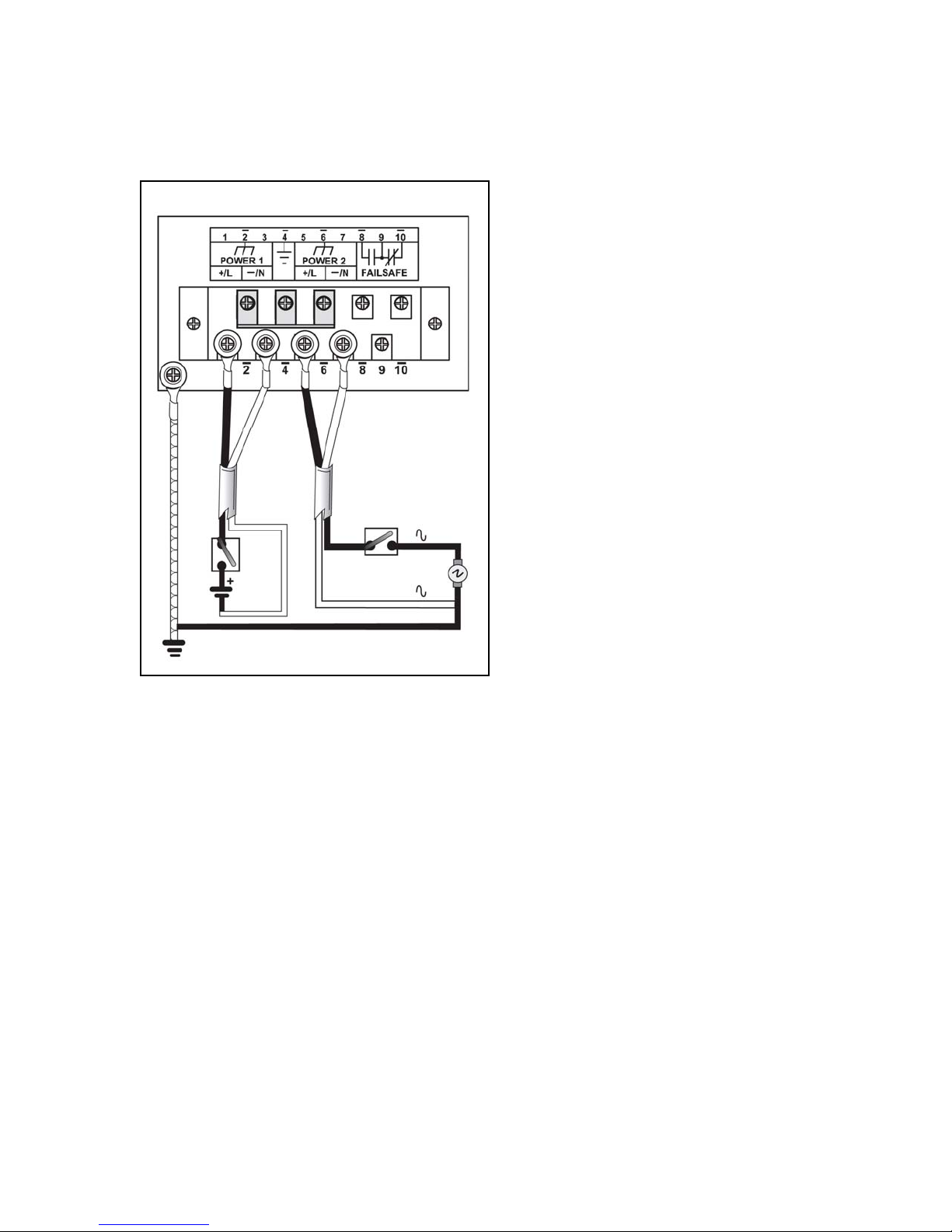
4.2.3 Dual Power Supplies – DC and AC Inputs
Figure 8: DC And AC power supply wiring examples
NOTES:
1. 88-300VDC rated equipment: A 300VDC appropriately rated circuit breaker must be
installed within 3m of unit.
2. 100-240VAC rated equipment: A 250VAC appropriately rated circuit breaker must be
installed within 3m of unit.
3. A circuit breaker is not required for 48 or 24VDC rated power supplies.
4. Separate circuit breakers must be installed and separately identified.
5. Equipment must be installed according to the applicable country wiring codes.
© 2008 RuggedCom Inc. All rights reserved Rev105
16
Page 17
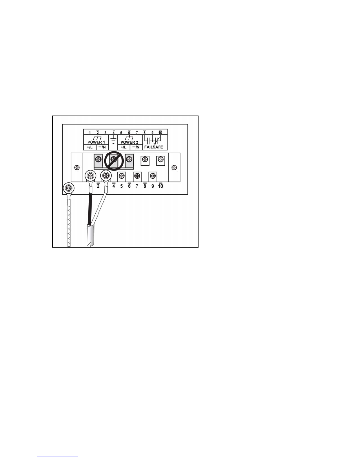
4.3 Dielectric Strength (HIPOT) Testing
For dielectric strength (HIPOT) testing in the field, users must remove the metal jumper located on
terminal 2, 4, and 6 of the power supply terminal block. This metal jumper connects transient
suppression circuitry to chassis ground and must be removed in order to avoid damage to transient
suppression circuitry during HIPOT testing. Figure 9 shows the proper HIPOT test connections
and should be followed to avoid damage to the device.
Figure 9: Dielectric Strength (HIPOT) Testing
© 2008 RuggedCom Inc. All rights reserved Rev105
17
Page 18
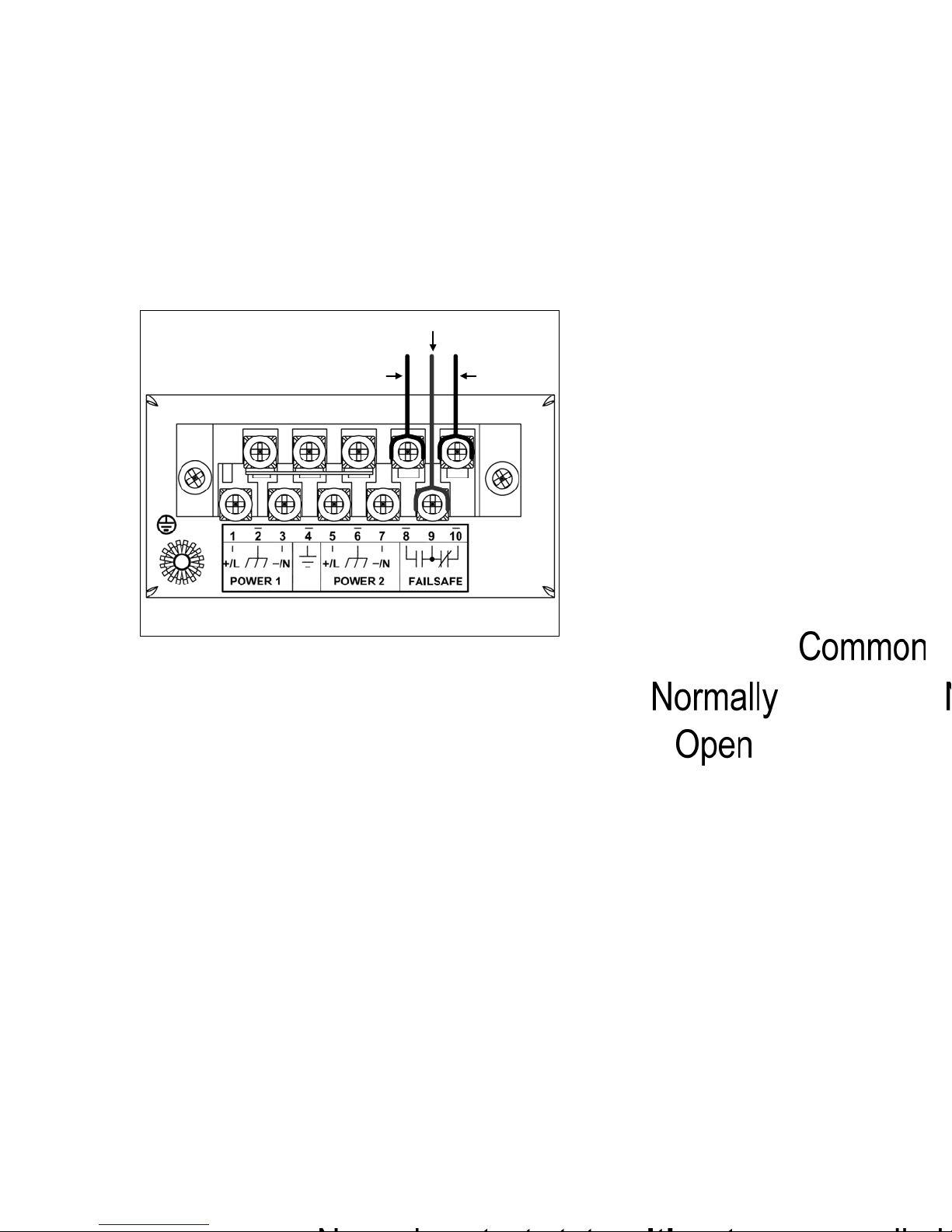
4.4 Failsafe Alarm Relay Wiring and Specifications
The “Failsafe” output relay is provided to signal critical error conditions that may occur on the
M2000 series products. The contacts are energized upon power up of the unit and remain
energized until a critical error occurs. The proper relay connections are shown in Figure 10. One
common application for this output is to signal an alarm if a power failure or removal of control
power occurs.
Figure 10: Failsafe Alarm Relay Wiring
© 2008 RuggedCom Inc. All rights reserved Rev105
18
Page 19
4.5 Console Port Wiring
2
)
2 5
)
3 6
4
8
7
1*
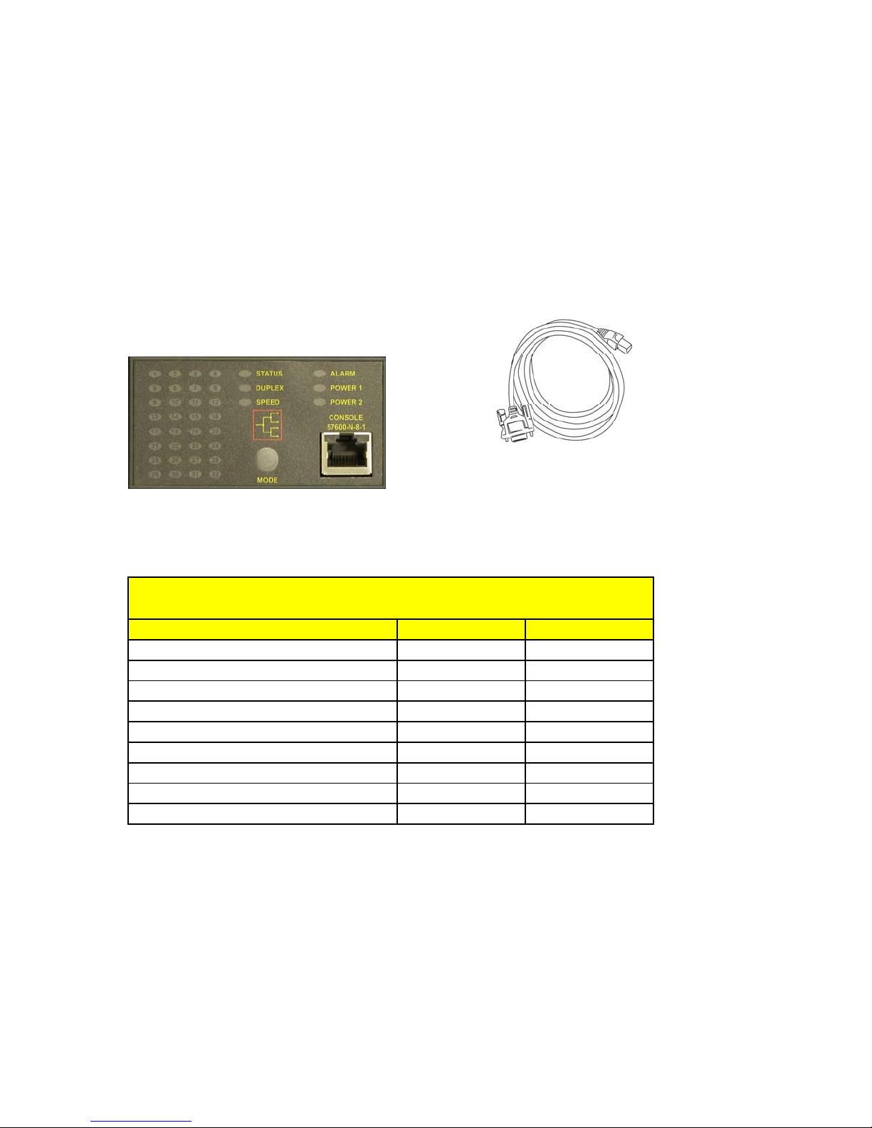
A RS232 console port for configuration and management of the device is located on the LED
display module shown in Figure 11. This port is intended to be a temporary connection during
initial configuration or troubleshooting and allows for direct access to the serial-based management
console. The connection is made using the DB9-Female to RJ45 console cable included in the
device packaging shown in Figure 12. Console connection settings are: 57600 baud, no parity
bits, 8 data bits, and 1 stop bit.
Figure 11: Console port location on display board Figure 12: M2200 Console cable
For user reference, the console cable pin-out is show in Table 5.
RuggedCom RS232 over RJ45 pin-out specification
Signal Name (PC is DTE) DB9- Female
RJ45 Male
DCD – Carrier detect 1
RxD – Receive data (to DTE
TxD – Transmit data (from DTE
DTR – Data terminal ready 4 3
Signal GND 5
DSR – Data set ready 6 1*
RTS – Ready to send 7
CTS – Clear to send 8
RI – Ring Indicator 9
Table 4: RS232 over RJ45 console cable pin-out
After initial configuration, the RuggedSwitch device can be configured via a number of new
mechanisms such as Telnet, and the built-in web server. Consult the RuggedSwitch ROS User
Guide for further details.
NOTE: This port is not intended to be a permanent connection and the cable shall be less than 2m
(6.5 ft) in length.
© 2008 RuggedCom Inc. All rights reserved Rev105
19
Page 20
4.6 Twisted-Pair Data Ports
4.6.1 Micro-D Twisted-Pair Data Ports
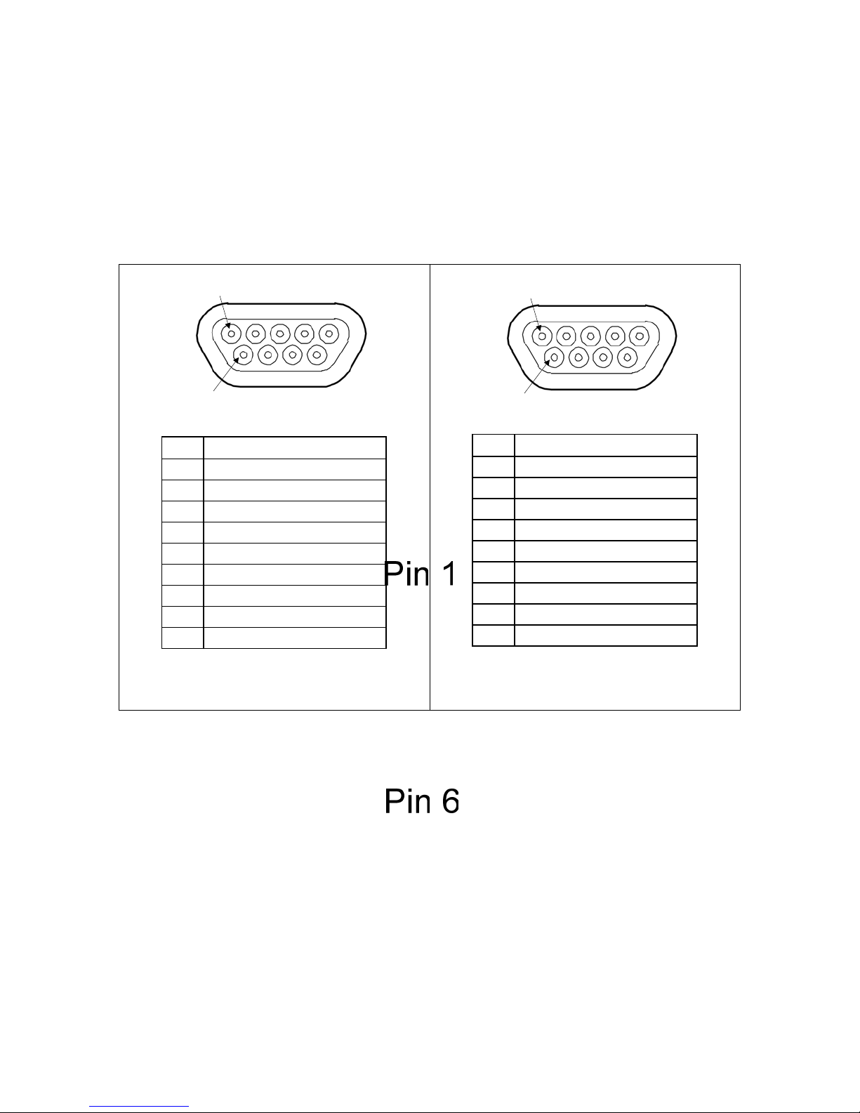
The M2100 may have several 10/100/1000BaseTX ports that allow connection to standard CAT-5
UTP cable with Micro-D connectors. Figure 13 shows the Micro-D port pin configuration.
Pin Signal
1TX+
2 No Connection
3 No Connection
4 No Connection
5RX+
6TX7 No Connection
8 No Connection
9RX-
Micro-D 10/100BaseTX port pin-out
Figure 13: Micro-D port pin configuration
NOTES:
1. For 10/100Base-TX ports: pin2 and pin7 are internally connected, pin4 and pin8 are internally
connected on PCB board.
2. For 10/100/1000Base-TX ports: pin3 and pin8 are internally connected on PCB board.
Pin Signal
1TP1+ (B+)
2 TP3+ (D+)
3 No Connection
4 TP2+ (C+)
5TP0+ (A+)
6 TP1- (B-)
7 TP3- (D-)
8 TP2- (C-)
9 TP0- (A-)
Micro-D 10/100/1000BaseTX port pin-out
© 2008 RuggedCom Inc. All rights reserved Rev105
20
Page 21

4.6.2 Protection on Twisted-Pair Data Ports
RuggedCom does not recommend the use of CAT-5 cabling of any length for critical real-time
substation automation applications. However, transient suppression circuitry is present on all
copper ports to protect against damage from electrical transients and to ensure IEC 61850-3 and
IEEE 1613 Class 1 conformance. This means that during the transient event communications
errors or interruptions may occur but recovery is automatic.
RuggedCom also does not recommended to use these ports to interface to field devices across
distances which could produce high levels of ground potential rise, (i.e. greater than 2500V) during
line to ground fault conditions.
© 2008 RuggedCom Inc. All rights reserved Rev105
21
Page 22
4.7 Gigabit Ethernet 1000Base-Tx Cabling Recommendations
The IEEE 802.3ab Gigabit Ethernet standard defines 1000Mbit/s Ethernet communications over
distances of up to 100 meters using 4 pairs of category 5 (or higher) balanced unshielded twistedpair cabling. For wiring guidelines, system designers and integrators should refer to the
Telecommunications Industry Association (TIA) TIA/EIA-568-A wiring standard that characterizes
minimum cabling performance specifications required for proper Gigabit Ethernet operation. To
ensure reliable, error-free data communications, new and pre-existing communication paths should
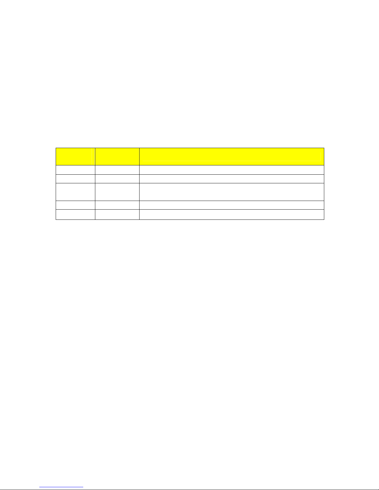
be verified for TIA/EIA-568-A compliance. Table 5 summarizes cabling standards available today.
Cabling
Category
< 5 No New wire infrastructure required
5 Yes Verify TIA/EIA-568-A complianc e
5e Yes No action required. New installations should be designed with
6 Yes No action required
> 6 Yes Connector and cabling standards to be determined.
Table 5: Cabling categories and 1000BaseTx compliance defined.
In general the following recommendations should be followed for copper data cabling in high
electrical noise environments:
• Data cable lengths should be as short as possible, ideally limited to 3m (10ft) in length.
Copper data cables should not be used for inter-building communications.
• Power and data cables should not be run in parallel for long distances, and ideally should be
installed in separate conduits. Power and data cables should intersect at 90° angles when
necessary to reduce inductive coupling.
• Shielded/screened cabling can optionally be used. The cable shield should be grounded at
one single point to avoid the generation of ground loops.
1000BaseTx
Compliant
Required action
Category 5e components or higher
© 2008 RuggedCom Inc. All rights reserved Rev105
22
Page 23
5 Technical Specifications
5.1 Power Supply Specifications
Input Range Power Supply Type
Min Max
12 – 24 VDC 10 VDC 36 VDC 6.3A(F) 2
24 VDC 18 VDC 36 VDC 5A(F) 2
48 VDC 36 VDC 59 VDC 2A(T) 2
HI (125/250 VDC) 1
HI (110/230 VAC)
1
88 VDC
85 VAC
300 VDC
265 VAC
NOTES:
1. This is the same power supply for both AC and DC.
2. (F) Denotes fast-acting fuse, (T) denotes time-delay fuse
3. Power consumption varies based on configuration. 10/100Tx ports consume roughly 1W
less than fiber optic ports.
4. For continued protection against risk of fire, replace only with same type and rating of fuse.
Fuse
Rating
2A(T)
1,2
Max. Power
Consumption
22W
3
5.2 Failsafe Relay Specifications
Parameter Value (Resistive Load)
Max Switching Voltage 240VAC, 125VDC
Rated Switching Current 2A @ 240VAC
0.15A @ 125VDC, 2A @ 30VDC
Max Switching Capacity 150W, 500VA
© 2008 RuggedCom Inc. All rights reserved Rev105
23
Page 24
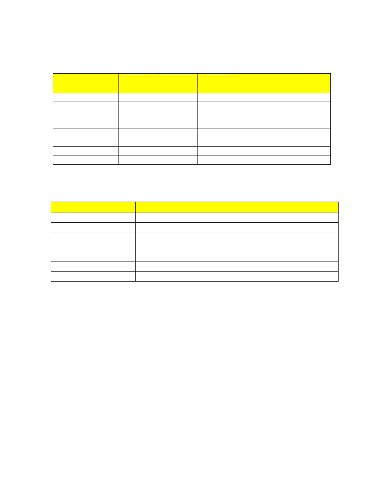
5.3 Networking Standards Supported
Parameter
IEEE 802.3 10BaseT / 10BaseFL
IEEE 802.3u 100BaseTX / 100BaseFX
IEEE 802.3z
IEEE 802.3ab
IEEE 802.3x
IEEE 802.1D
IEEE 802.1Q
IEEE 802.1p
10Mbps
Ports
9 9 9
9 9
9 9
9 9
100Mbps
Ports
1000Mbps
Ports
9
9
9
9
9
Notes
1000BaseSX/LX
1000BaseTx
Full Duplex Operation
MAC Bridges
VLAN (Virtual LAN)
Priority Levels
5.4 Twisted-Pair Port Specifications
Parameter Specification Notes
Speed 10/100 Mbps Auto-negotiating
Duplex FDX / HDX Auto-negotiating
Cable-Type > Category 5 Shielded/Unshielded
Wiring Standard TIA/EIA T568A/B Auto-Crossover, Auto-polarity
Max Distance 100m
Connector RJ45
Isolation 1.5kV RMS 1-minute
24
© 2008 RuggedCom Inc. All rights reserved Rev105
Page 25
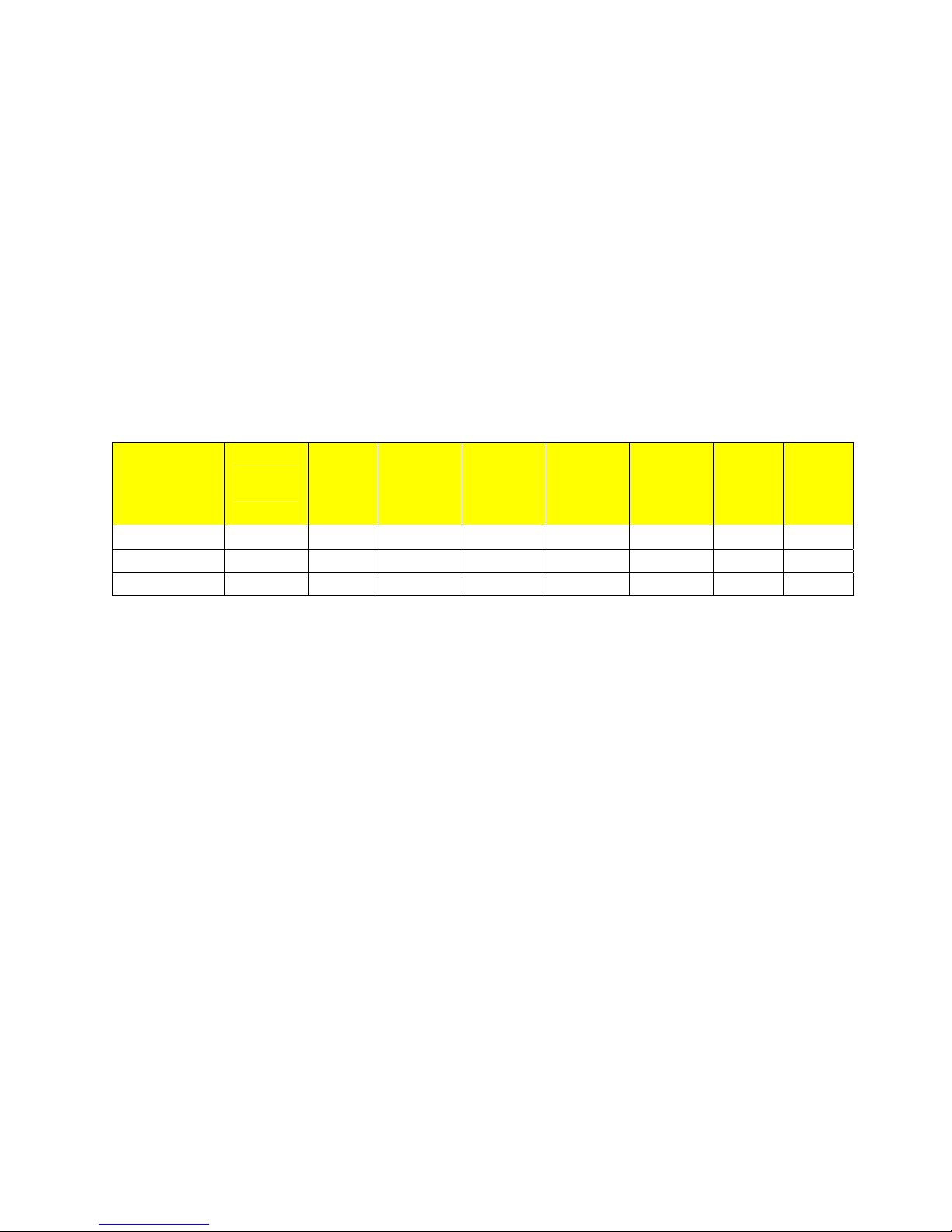
5.5 Fiber Optical Specifications
The following sections detail fiber optical specifications on ports that can be ordered with the
M2200 series Ethernet switch. The user determines the type of optics at time of ordering, and can
determine the modules installed on a particular unit by reading the factory data file via the
RuggedSwitch ROSTM user interface. The following sections detail specifications of fiber optic
modules in Gigabit Ethernet (1000Mbps).
5.5.1 Gigabit Ethernet (1000Mbps) Modules
For maximum flexibility RuggedCom Inc. offers a number of different transceiver choices for
Gigabit fiber optical communications. The following table details fiber optic specifications based on
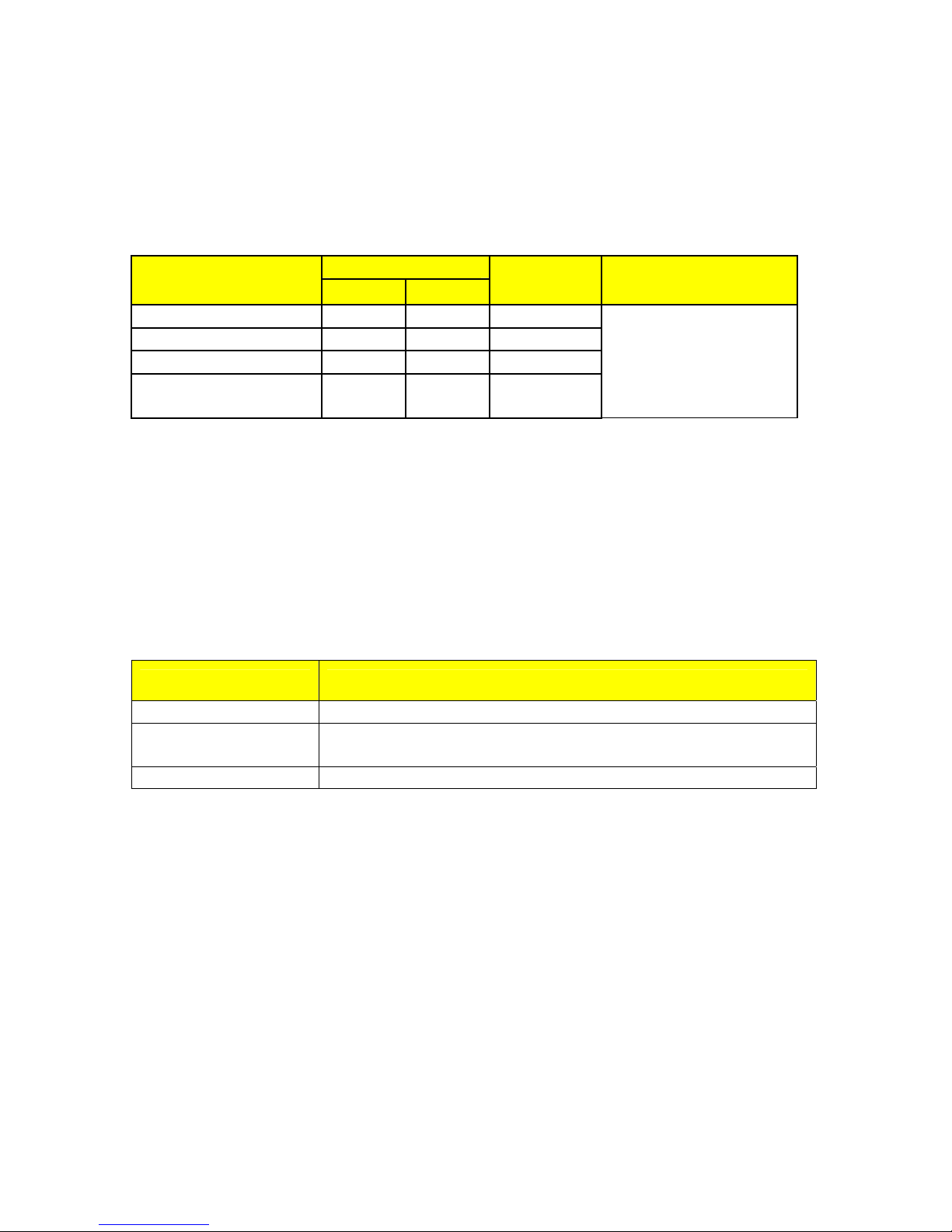
the 2-port modules or pluggable transceivers selected at time of ordering.
Optics
Order Code
Mode /
Connector
Tx λ
(nm)
12-11-0036 MM / LC 850
12-11-0027 SM / LC 1310
12-11-0028 SM / LC 1310
Cable
Type2
50μ/125
9μ/125
9μ/125
Tx Pwr
(dBm) 3
(Min/Max)
-9.5 / -4 -20 0 0.5 13
-9.5 / -3 -22 -3 10 18.5
-5 / 0 -22 -3 25 19.5
Rx
Sensitivity
(dBm) 3
Rx
Saturation
(dBm) 3
NOTES:
1. Maximum segment length is greatly dependent on factors such as fiber quality, and
number of patches and splices. Please consult RuggedCom sales associates when
determining maximum segment distances.
2. All cabling is duplex type unless otherwise specified.
3. All optical power numbers are listed as dBm averages.
4. These transceivers utilize a distributed feedback (DFB) type laser and are rated for -20°C
to +85°C operation only.
Typical
Distance
(km)1
Power
Budget
(dB)
© 2008 RuggedCom Inc. All rights reserved Rev105
25
Page 26
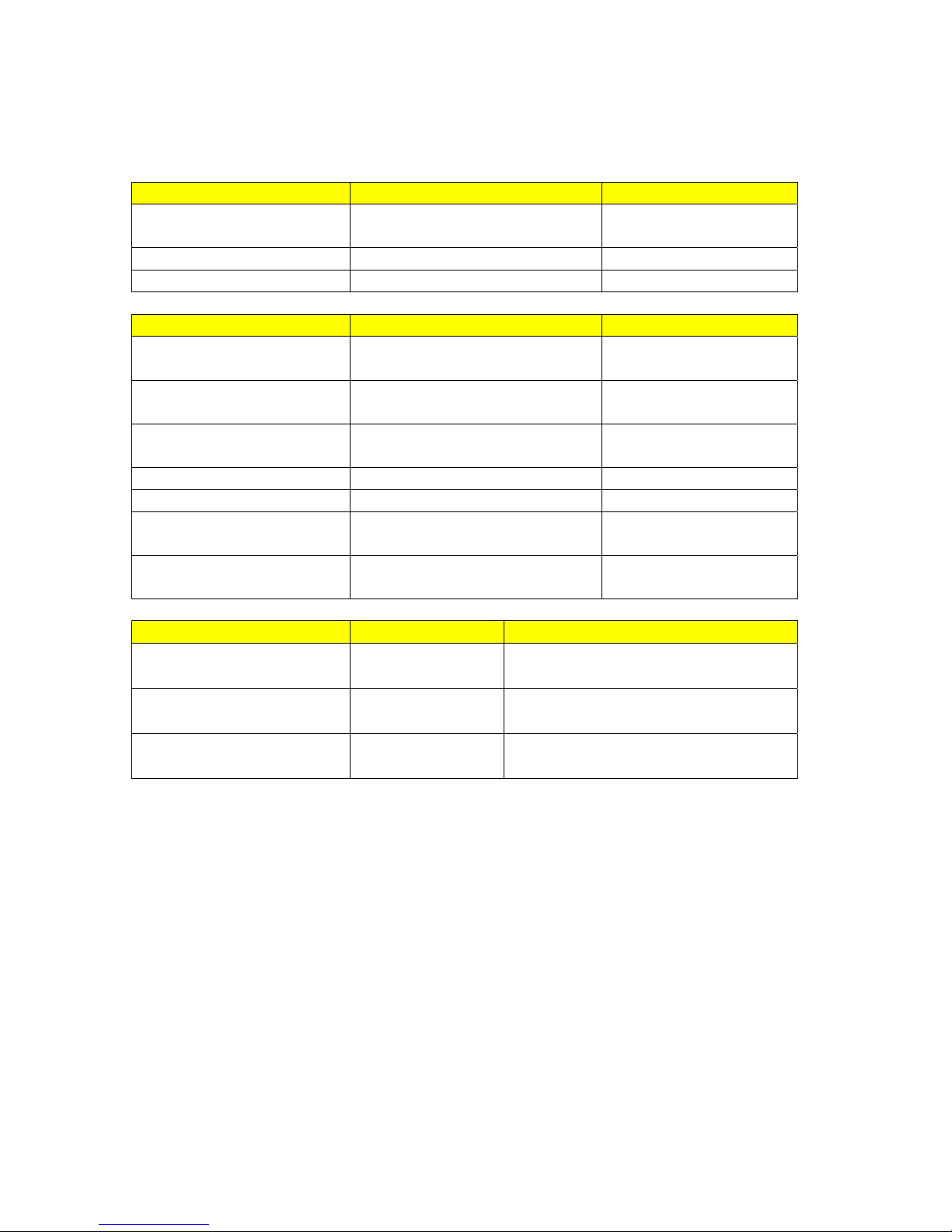
5.6 Type Test Specifications
Electrical Safety Levels Comments
Dielectric Withstand 2 kV RMS for 1 minute
High Voltage Impulse 5 kV peak IEC 60255-5 (Section 8)
Insulation Resistance 500 VDC for 1 minute IEC 60255-5 (Section 6
Electrical Environment Levels Comments
High Frequency Disturbance
(Oscillatory)
IEC Surge 4 kV / 2 kV
IEC Fast Transient 2 kV / 1 kV
ANSI/IEEE Fast Transient 4 kV ANSI/IEEE C37.90.1
IEC Radiated RFI Immunity 10 V/m IEC 61000-4-3
ANSI/IEEE Radiated RFI
Immunity
ESD
(Electrostatic Discharge)
Atmospheric Environment Levels Comments
Temperature (Dry Cold)
Temperature (Dry Heat)
Humidity
2.5 kV @ 1MHz for 2s
20 V/m ANSI/IEEE C37.90.2
15 kV (air discharge)
8 kV (contact)
-40°C
85°C
95%
non-condensing
Test Db: 6 cycles, 55°C, 95% Humidity
ANSI/IEEE C37.90 (1989)
IEC 60255-5 (Section 6)
ANSI/IEEE C37.90.1
IEC 60255-22-1
IEC 61000-4-5
(Level 4)
IEC 61000-4-4
(Level 4)
IEC 61000-4-2
(Level 4)
IEC 60068-2-1
Test Ad: 16 hrs @ -40°C
IEC 60068-2-2
Test Bd: 16 hrs @ 85°C
IEC 60068-2-30
© 2008 RuggedCom Inc. All rights reserved Rev105
26
Page 27

5.7 Operating Environment
Parameter Range Comments
Ambient Temperature as
Ambient Operating
Temperature
-40 to 85°C
Ambient Relative Humidity 5% to 95% Non-condensing
Ambient Storage
Temperature
-40 to 85°C
measured from a 30cm
radius surrounding the
center of the enclosure.
© 2008 RuggedCom Inc. All rights reserved Rev105
27
Page 28
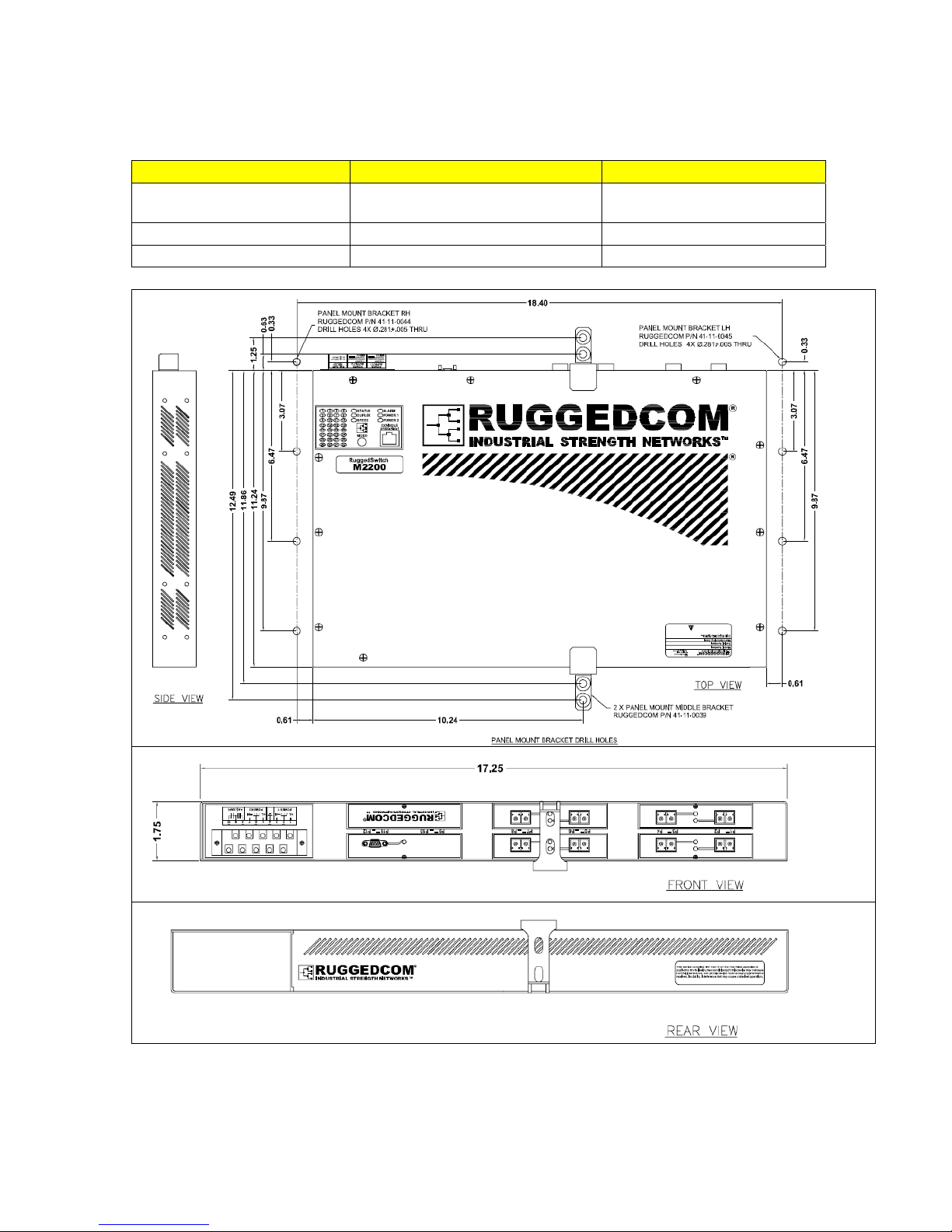
5.8 Mechanical Specifications
Parameter Value Comments
Dimensions 19.00 x 14.50 x 2.02 inches
(482.6) x (368.3) x (51.3) mm
Weight 11.2 lb (5 Kg)
Enclosure 18awg galvanized steel
(Length x Width x Height)
with mounting brackets installed
with mounting brackets installed
Figure 14: Mechanical Dimensions
28
© 2008 RuggedCom Inc. All rights reserved Rev105
Page 29

6 Agency Approvals
Agency Standards Comments
CE Compliance is claimed
CE EN 60950, EN 61000-6-2
FCC FCC Part 15, Class A Passed
CISPR EN55022, Class A Passed
FDA/CDRH 21 CFR Chapter 1, Subchapter J Passed
IEC/EN EN60825-1:1994 + A11:1996 + A2:2001 Passed
via Declaration of Self
Conformity Route
7 Warranty
RuggedCom warrants this product for a period of five (5) years from date of purchase. For
warranty details, visit http://www.ruggedcom.com/ or contact your customer service representative.
Should this product require warranty or service contact the factory at:
RuggedCom Inc.
30 Whitmore Road
Woodbridge, Ontario
Canada L4L 7Z4
Phone: (905) 856-5288
Fax: (905) 856-1995
© 2008 RuggedCom Inc. All rights reserved Rev105
29
 Loading...