

Page 1
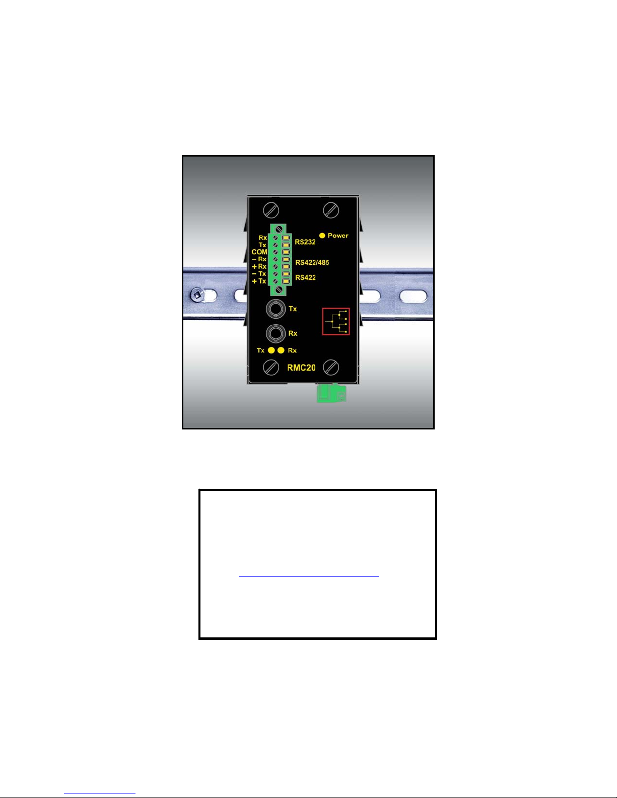
Rugged
MC
™ RMC20
Installation Guide
RuggedCom Inc.
30 Whitmore Road,
Woodbridge, Ontario
Canada L4L 7Z4
Web: http://www.ruggedcom.com/
Tel: (905) 856-5288
Fax: (905) 856-1995
Toll Free: (888) 264-0006
Page 2

Federal Communications Commission Radio Frequency Interference
Statement
This equipment has been tested and found to comply with the limits for a Class A digital device
pursuant to Part 15 of the FCC Rules. These limits are designed to provide reasonable protection
against harmful interference when the equipment is operated in a commercial environment. This
equipment generates, uses and can radiate radio frequency energy and, if not installed and used in
accordance with the instruction manual, may cause harmful interference to radio communications.
Operation of this equipment in a residential area is likely to cause harmful interference in which
case the user will be required to correct the interference on his own expense.
Warning:
user’s authority to operate the equipment.
Caution – Use of controls or adjustments or performance of procedures other than those specified
herein may result in hazardous radiation exposure. This product contains no user serviceable
parts. Attempted service by unauthorized personnel shall render all warranties null and void.
Should this device require service see the “Warranty and Service” section of this installation guide.
Changes or modifications not expressly approved by RuggedCom Inc. could void the
Caution – This product contains a laser system and is classified as a
“CLASS 1 LASER PRODUCT”
Important:
The RuggedMCTM should be installed in a restricted access location where access can only be
gained by service personnel or users who have been instructed about the reasons for the
restrictions applied to the location and about any precautions that shall be taken; and access is
through the use of a tool or lock and key, or other means of security, and is controlled by the
authority responsible for the location.
Trademarks:
Ethernet is a trademark of Xerox Corporation
Rugged MediaConverter and RuggedMC is a registered trademark of RuggedCom Inc.
© 2006 RuggedCom Inc. All rights reserved Rev100
2
Page 3

Table of Contents
1 Product Overview.................................................................................................................... 4
1.1 RMC20 Front Panel Description..................................................................................... 5
1.2 RMC20 Side and Bottom View........................................................................................ 6
2 Installation............................................................................................................................... 7
2.1 DIN Rail Mounting........................................................................................................... 7
2.2 Panel Mounting............................................................................................................... 8
2.3 Power Supply Wiring and Grounding..............................................................................9
2.4 Serial Ports – Signal Description...................................................................................10
2.4.1 RS232 Data Ports.....................................................................................................10
2.4.2 RS422 and RS485 Data Ports...................................................................................11
2.5 RMC20 Configuration....................................................................................................13
2.5.1 Serial-to-Fiber Conversion: Point-to-Point.................................................................14
2.5.2 Serial Standard Conversion.......................................................................................15
2.5.3 Serial-to-Fiber Conversion: Loop Topology..............................................................16
3 Specifications.........................................................................................................................17
3.1 Power Supply Specifications..........................................................................................17
3.2 Fiber Optical Port Specifications....................................................................................17
3.3 Mechanical Specifications .............................................................................................18
4 Type Test Specifications........................................................................................................19
4.1 Operating Environment..................................................................................................20
4.2 Agency Approvals..........................................................................................................20
5 Warranty.................................................................................................................................20
© 2006 RuggedCom Inc. All rights reserved Rev100
3
Page 4

1 Product Overview
INTRODUCTION
The RuggedMC™ series of media converters
are industrial hardened and specifically
designed to operate reliably in electrically harsh
and climatically demanding environments.
The RMC20 is a utility-grade, protocolindependent, serial-to-fiber and serial standards
converter for all your serial communication
requirements. The RMC20 allows RS485,
RS422, or RS232 devices or networks to
communicate over secure, noise immune,
optically isolated, fiber optic cabling at extended
distances as well convert RS232 to either
RS485 or RS422 serial standards.
The RMC20 was designed specifically to
provide years of maintenance free operation for
all your mission-critical, real-time control
applications. To ensure the utmost in reliability,
the RMC20 is tested to the most stringent
international EMI and environmental standards
for use in HV/MV electric utility substations and
factory floor applications. All RMC™ products
are packaged with a high reliability, built-in
power supply (24V, 48V, or HI Voltage options)
and enclosed in a rugged galvanized steel
enclosure suitable for panel or DIN-rail
mounting.
All RuggedCom Inc. products are backed by a
five-year warranty and unsurpassed technical
support.
PORT OPTIONS
Protocol independent RS485, RS422, or
RS232 (user selectable) conversion to
multimode fiber optics (ST connector only)
RS232 to RS485/RS422 conversion mode
Fully EIA/TIA RS485, RS422, RS232
compliant communications
Built-in, defeatable, RS485/RS422
termination networks
Point-to-point, or optical loop configurations
Full or half duplex configurable
Support for high-speed serial baud rates
from 300 to 115200 baud
UNIVERSAL POWER SUPPLY OPTIONS
24VDC, 48VDC or HI (88-300VDC / 85 -
264Vac) options for worldwide operability
Integrated high-reliability power supply
eliminates the need for external power
transformer
Screw down terminal blocks ensure reliable
maintenance-free connections
All power supplies CSA/UL 60950 approved
for +85°C (185°F) operation
DESIGNED FOR HARSH ENVIRONMENTS
Exceeds IEC 61850-3 and IEEE 1613
Standards for communication equipment in
electric power substations
Operates over a temperature range of -40 C
to +85 C without the use of fans for
improved reliability
18 AWG galvanized steel enclosure suitable
for DIN or panel mounting provide secure
mechanical reliability
SIMPLE PLUG AND PLAY OPERATION
Simple, externally-accessible configuration
Transmit and receive data LED indicators
for quick and easy troubleshooting
Fully integrated power supply connects
directly to power source permanently for
reliable maintenance-free operation
© 2006 RuggedCom Inc. All rights reserved Rev100
4
Page 5
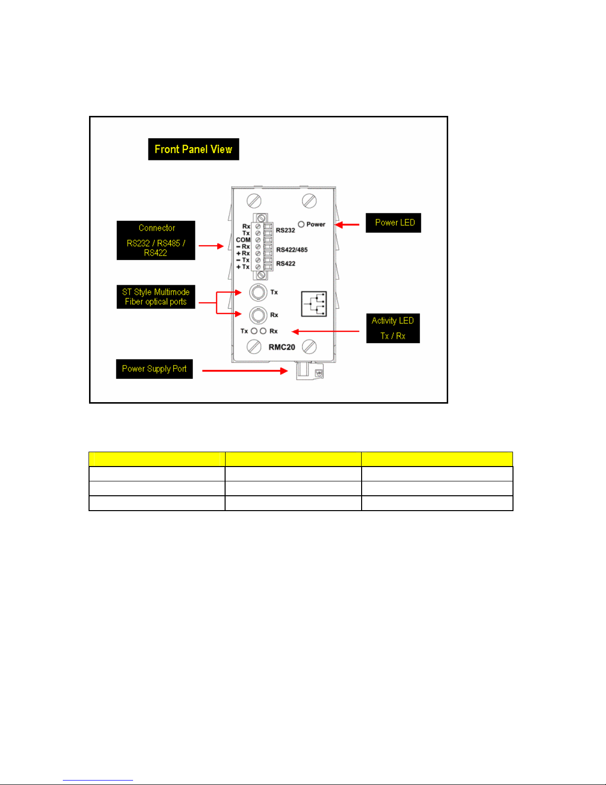
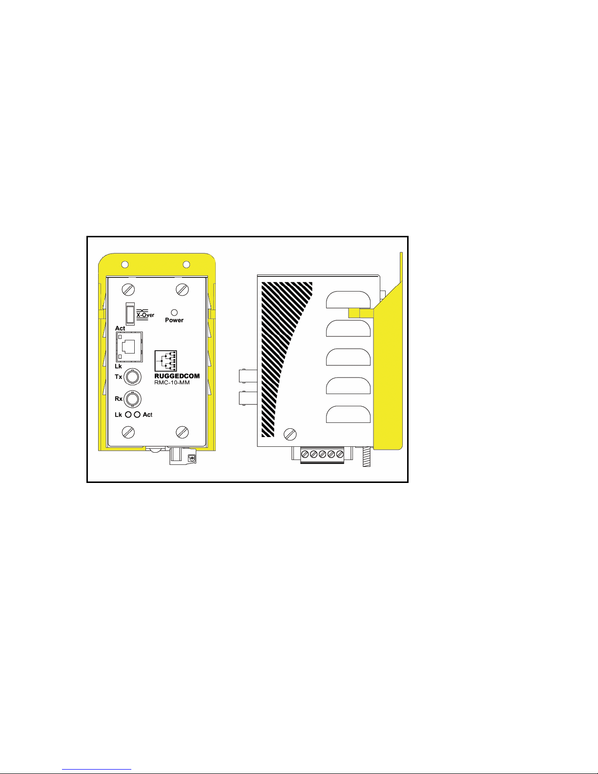
1.1 RMC20 Front Panel Description
Fig. 1.1.1 RMC20 Front Panel Detail
The RMC20 LED definitions are as follows:
ITEM Activity Comments
Tx LED Blinking (Yellow) Transmitting Serial Data
RX LED Blinking (Yellow) Receiving Serial Data
Power LED Solid (Green) Power On
© 2006 RuggedCom Inc. All rights reserved Rev100
5
Page 6
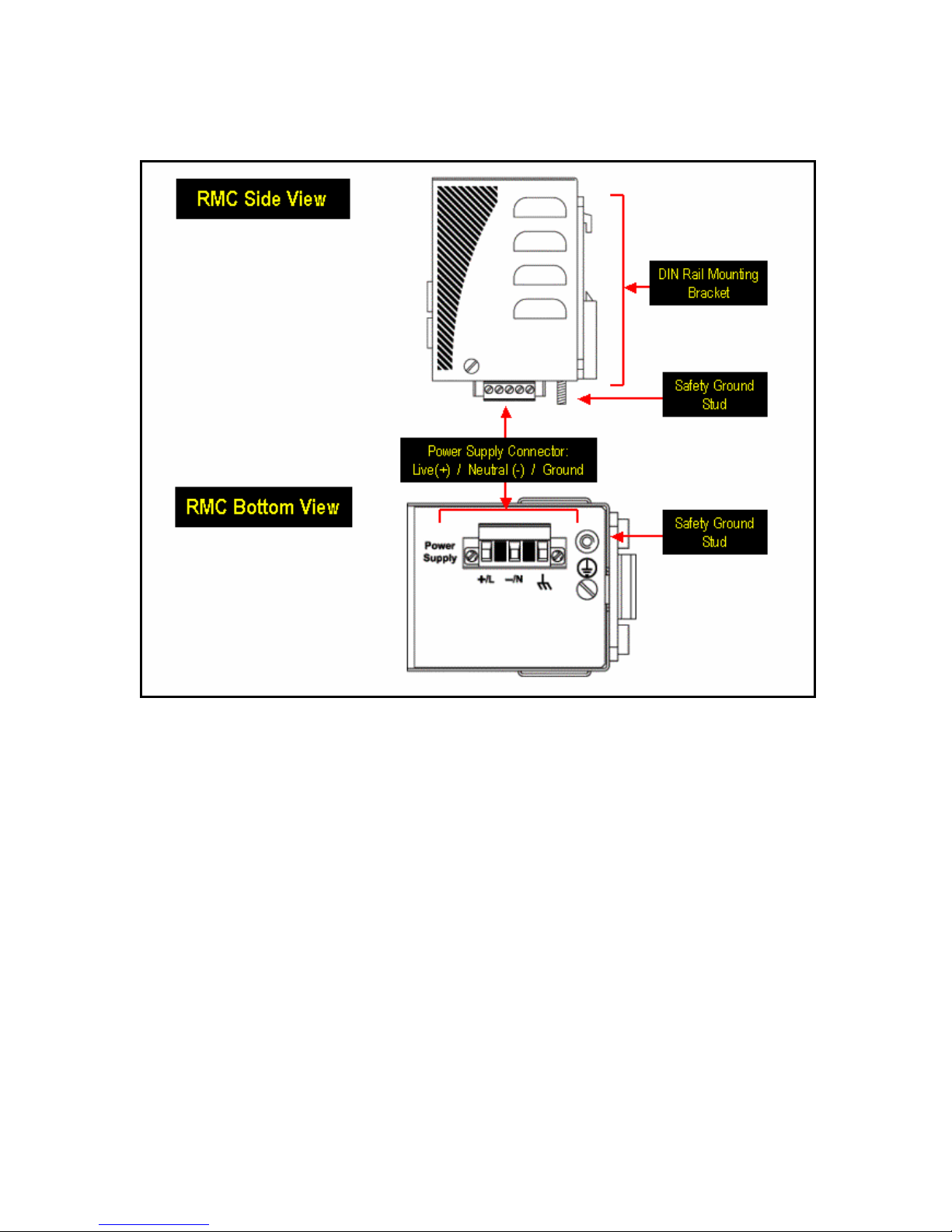
1.2 RMC20 Side and Bottom View
Fig. 1.2.1 RMC20 Side and Bottom View
6
© 2006 RuggedCom Inc. All rights reserved Rev100
Page 7
2 Installation
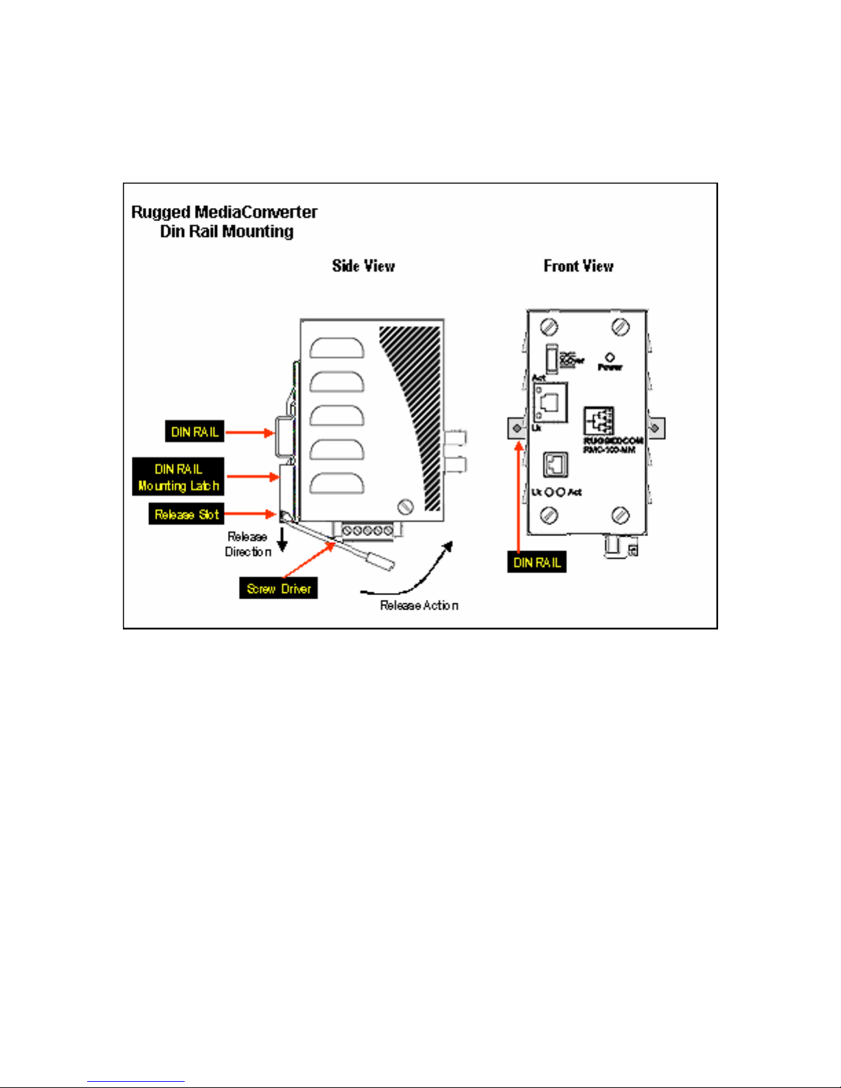
2.1 DIN Rail Mounting
Fig. 2.1.1 RuggedMCTM DIN Rail Mounting
7
© 2006 RuggedCom Inc. All rights reserved Rev100
Page 8
2.2 Panel Mounting
With the use of an optional panel-mount adapter, the RuggedMCTM series of media converters can
be panel mounted. The drawing shown in Figure 2.2.1 shows an example of an RMC unit panel
mounted using the optional panel mount adapter.
The panel mount adapter can be secured to a panel with three screws. The RuggedMCTM product
is easily mounted onto the panel mount adapter via the two metal clips on either side of the unit,
and a single screw located on the bottom.
Figure 2.2.1: RuggedMC
TM
© 2006 RuggedCom Inc. All rights reserved Rev100
panel mounted using optional panel mount mounting adapter.
8
Page 9
2.3 Power Supply Wiring and Grounding
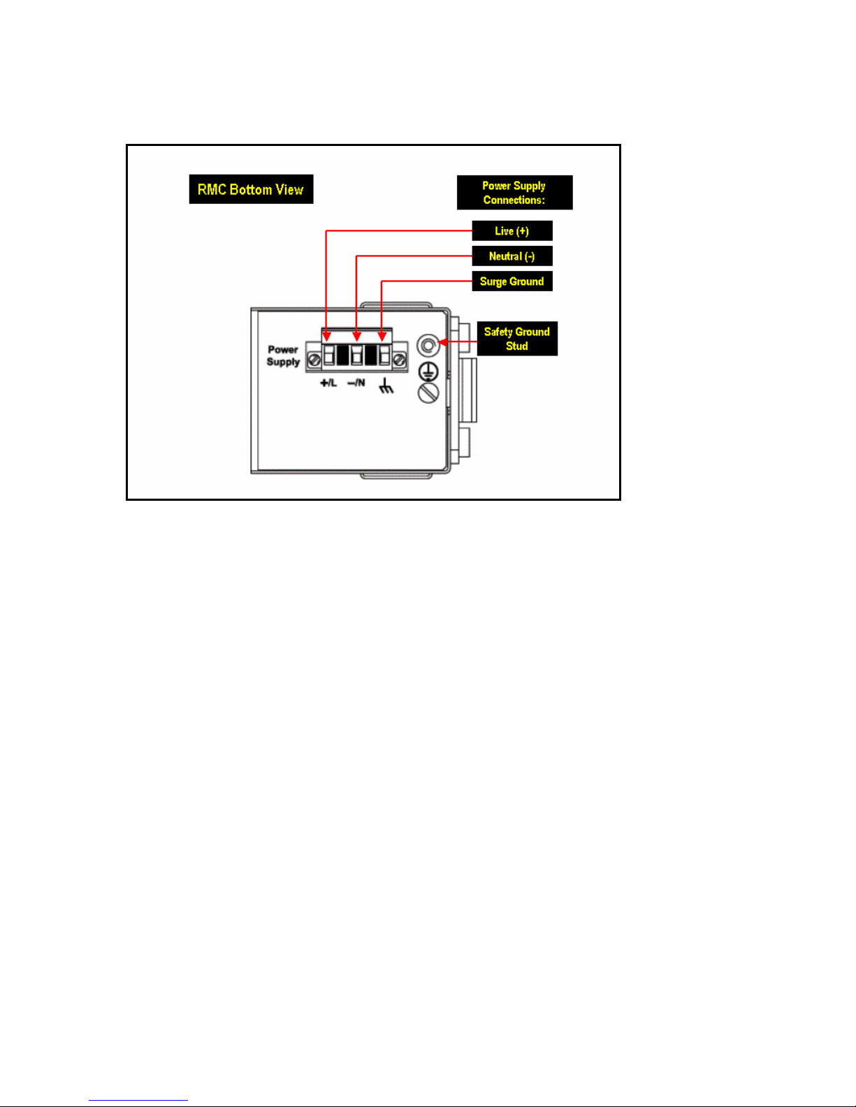
Fig. 2.2.1 RuggedMCTM Power Supply Inputs
The RuggedMCTM power supply inputs are identical and are connected as follows:
1. +/L = DC (+) / AC (Hot) is connected to the positive (+) terminal if the power source is DC
or to the (Hot) terminal if the power source is AC.
2. -/N = DC (-) / AC (Neutral) is connected to the negative (-) terminal if the power source is
DC or to the (Neutral) terminal if the power source is AC.
3. Surge Ground is connected to the Safety Ground via a braided cable or other appropriate
grounding wire. Surge Ground is used as the ground conductor for all surge and transient
TM
suppression circuitry internal to the RuggedMC
4. Safety Ground should be connected to the power supply ground. This should be the
safety ground for AC inputs or the equipment ground bus for DC inputs.
Note: Surge Ground must be disconnected from Chassis Ground during HIPOT
(Dielectric strength) testing.
Notes:
1. For 125/250VDC rated equipment: An appropriately rated 300VDC circuit breaker
must be installed within 3 meters of unit.
2. For 110/230VAC rated equipment: An appropriately rated 250VAC circuit breaker
must be installed within 3 meters of the unit
3. A circuit breaker is not required for 48 or 24VDC rated equipment.
4. For multiple supplies, separate circuit breakers must be installed. Equipment must
be installed according to the applicable country wiring codes.
.
© 2006 RuggedCom Inc. All rights reserved Rev100
9
Page 10
2.4 Serial Ports – Signal Description
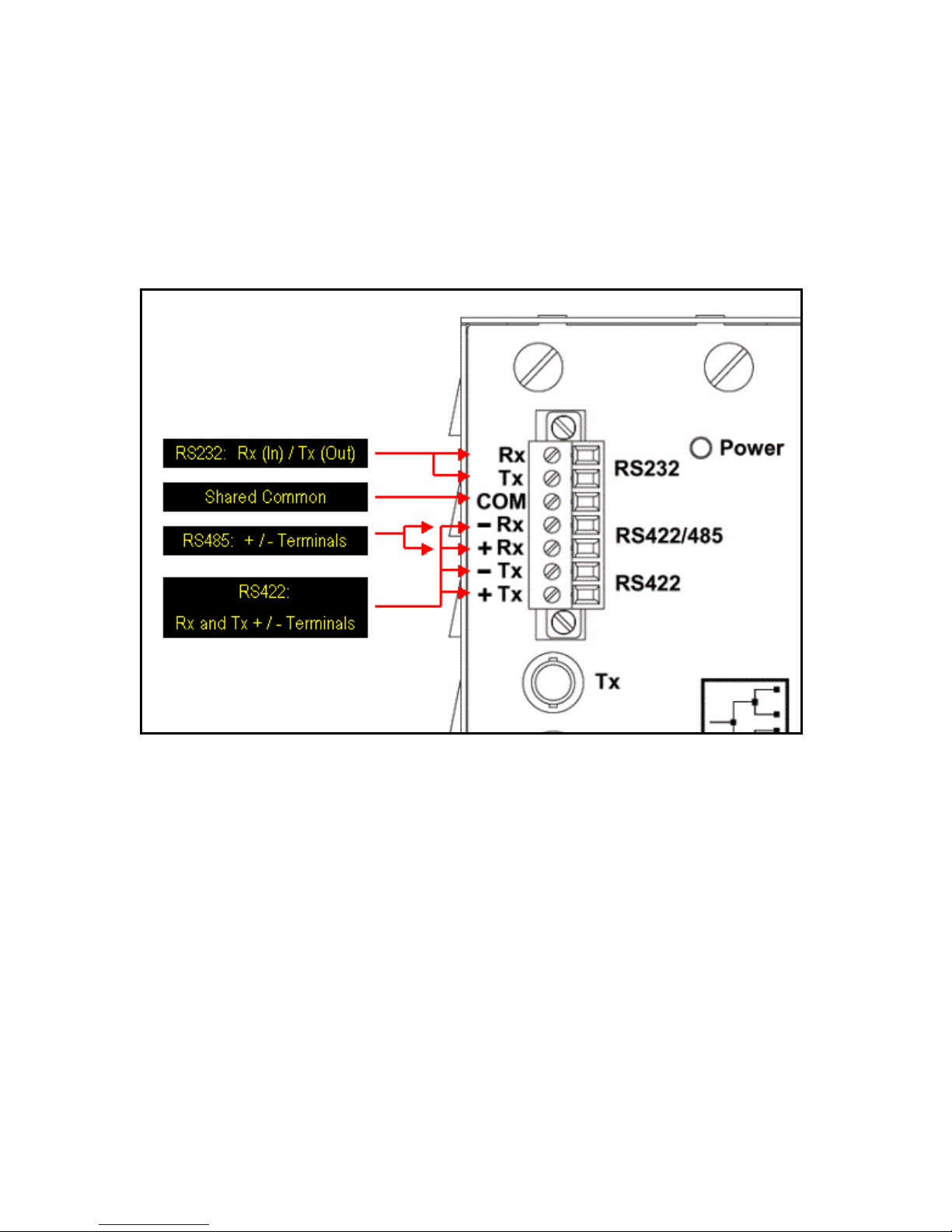
The RMC20 is equipped with a seven-terminal phoenix style connector. This connector can
accommodate one RS232 connection, and one RS485/422 connection. Figure 2.4 shows the
connections for RS232, RS485, and RS422 communications. The following sections describe
installation details for respective ports.
Figure 2.4: Serial RS232, RS485, and RS422 terminal block connections
2.4.1 RS232 Data Ports
The RMC20 is equipped with a single EIA/TIA RS232 compliant port, consisting of three terminals:
Transmit, Receive, and Common. The RS232 port is intended for point-to-point applications
only. The EIA/TIA guidelines for RS232 communications include (but are not limited to) the
following:
1. To minimize the effects of ambient electrical noise, shielded cabling is recommended.
2. Reliable communications within 15m. Greater distances are possible.
3. Communications of up to 120kbaud signal rate.
10
© 2006 RuggedCom Inc. All rights reserved Rev100
Page 11

2.4.2 RS422 and RS485 Data Ports
The RMC20 is equipped with a single RS485 / RS422 data port. In half duplex mode (See section
2.5 for RMC20 DIP switch settings) the RS485 connections (Rx +, Rx -, COM) should be
connected. In full-duplex mode the RS422 connections (Rx+, Rx -, Tx+, Tx-, COM) should be
connected. Both RS485 and RS422 can accommodate multi-drop networks, for master-slave
serial network communications. For both RS485 / RS422 connections, the following general
guidelines should be followed:
1. To minimize the effects of ambient electrical noise, shielded cabling is recommended
2. The correct polarity must be observed throughout the daisy chain
3. The number of devices wired should not exceed 32, and total distance should be less than
4000 feet (at 100Kbps)
4. The COM terminal should be connected to the common wire inside the shield.
5. The shield/COM should be grounded at ONE single point to avoid loop currents
6. The twisted pair should be terminated at each end of the chain. (Typically with a 120Ohm
resistor and a 10nF capacitor in series across the twisted pair)*
* Both data terminal pairs (Rx +/- and Tx +/-) are terminated by default from the factory. To
remove termination: Open the cover and remove jumper JP1 and/or JP2 (JP1 for Rx+, Rxterminals, JP2 for Tx+, Tx- terminals) depending on which port termination is NOT required.
Termination provided is a 120 Ohm resistor in series with a 10nF capacitor as per the ModBus 1.0
specification. In general termination should be left in place unless it is detrimental to
communications.
Note: Transient protection is provided on all RMC20 terminals. Lightning strikes and ground surge
currents can cause large momentary voltage differences between ends of communication links. To
ensure maximum reliability of the entire link, all equipment should have similar transient protection
installed.
Figure 2.4.2.1 details an example RS485 wiring diagram.
© 2006 RuggedCom Inc. All rights reserved Rev100
11
Page 12
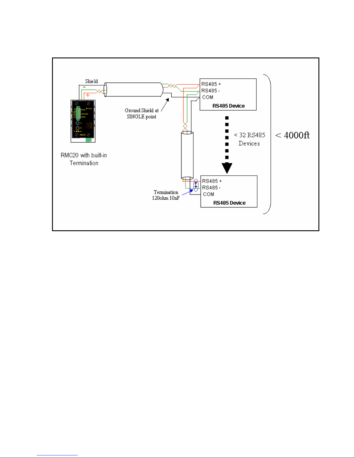
Fig 2.4.2.1 Conceptual RS485 wiring diagram
© 2006 RuggedCom Inc. All rights reserved Rev100
12
Page 13
2.5 RMC20 Configuration
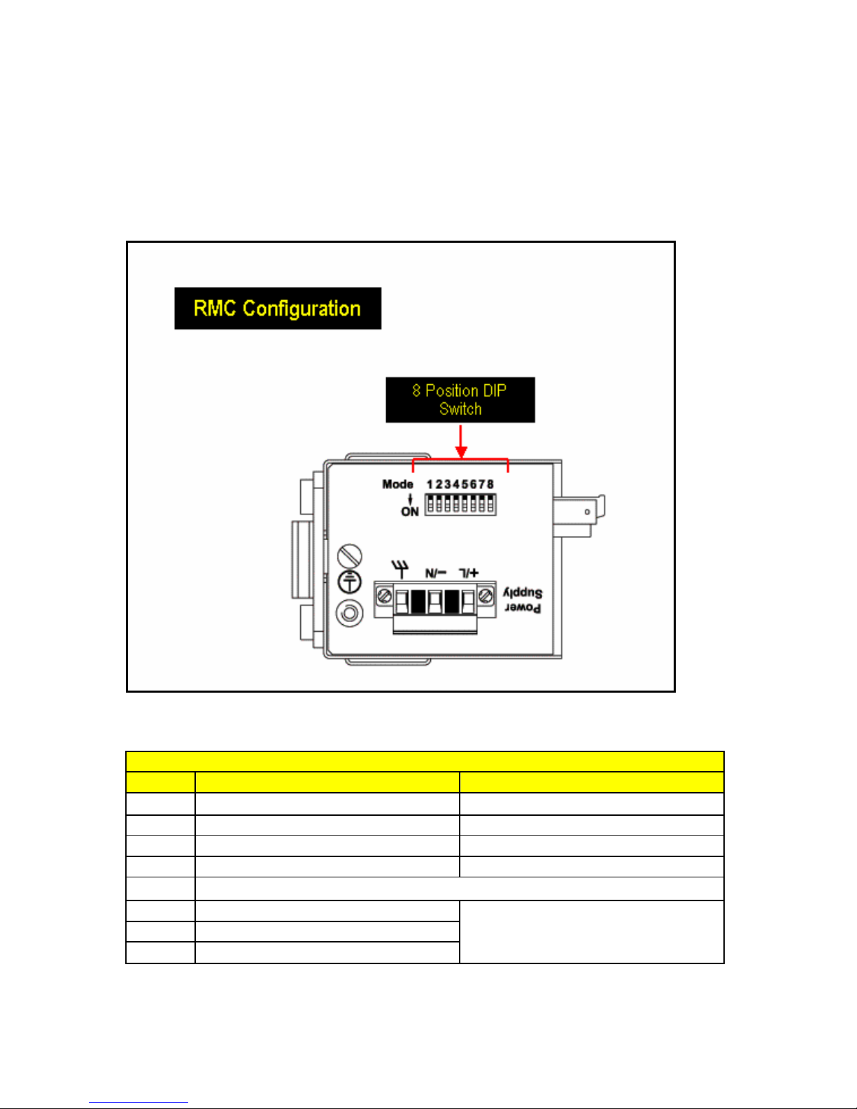
The RMC20 can be configured using the DIP switches located at the bottom of the enclosure. The
DIP switches are shown in Figure 2.5.1. Using the switches one can change the operating mode
of the RMC20.
Figure 2.5.1. RMC20 8-Position DIP switch location for configuration
RMC20 DIP Switch Configuration Settings Defined
Position ON OFF
1 RS232 to fiber mode RS485/422 to fiber mode
2 RS232 to RS485/422 conversion mode Serial (RS232/485/422) to fiber mode
3 Full Duplex Serial (RS232 / RS422) Half Duplex Serial (RS485)
4 Fiber Repeat ON Fiber Repeat OFF
5 RESERVED
6 > 57600 baud
7 19200 – 57600 baud
300 – 2400 baud
8 4800 – 14400 baud
13
© 2006 RuggedCom Inc. All rights reserved Rev100
Page 14
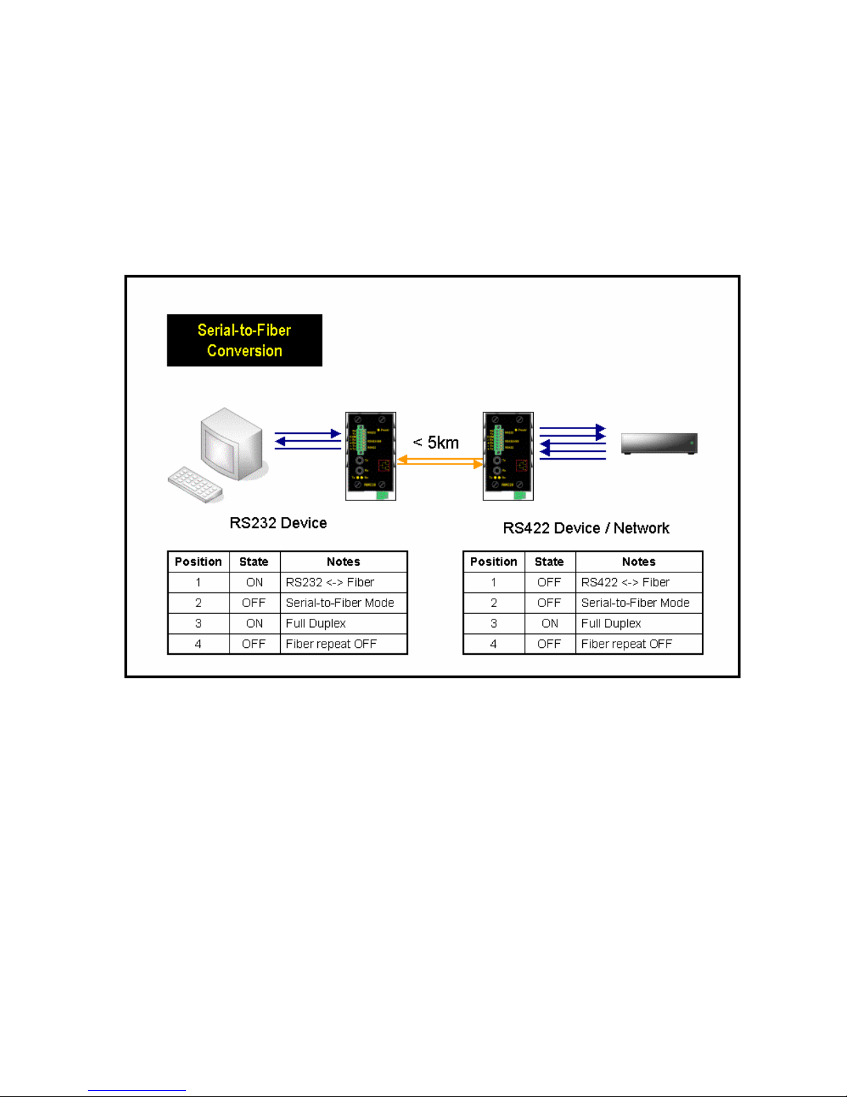
The RMC20 is equipped to provide conversion from serial (RS232, RS485, or RS422) to fiber
optics, or between serial standards (RS232 to RS485 / RS422). Serial to fiber optic conversion
connections can be further implemented in point-to-point, as well as optical loop configurations. To
better illustrate all working modes, figure Section 2.5.1 through 2.5.3 will show example
configuration options, and relevant DIP switch settings.
2.5.1 Serial-to-Fiber Conversion: Point-to-Point
Figure 2.5.1.1 Serial-to-Fiber point-to-point topology
Figure 2.5.1.1 illustrates the serial-to-fiber conversion mode of operation. In this mode serial data
is converted directly into light impulses, and transmitted over multimode fiber optics. The serial
standard is selected by position 1 of the DIP switches: OFF (default) is for RS485 / RS422, and
ON is for RS232. Position 2 should be OFF for serial to fiber conversion. Position 6-8 should be
configured if RS485 communications are used, in order to have the appropriate turn-around timer
selected. Positions 6-8 do not impact communications in full-duplex mode.
14
© 2006 RuggedCom Inc. All rights reserved Rev100
Page 15
2.5.2 Serial Standard Conversion
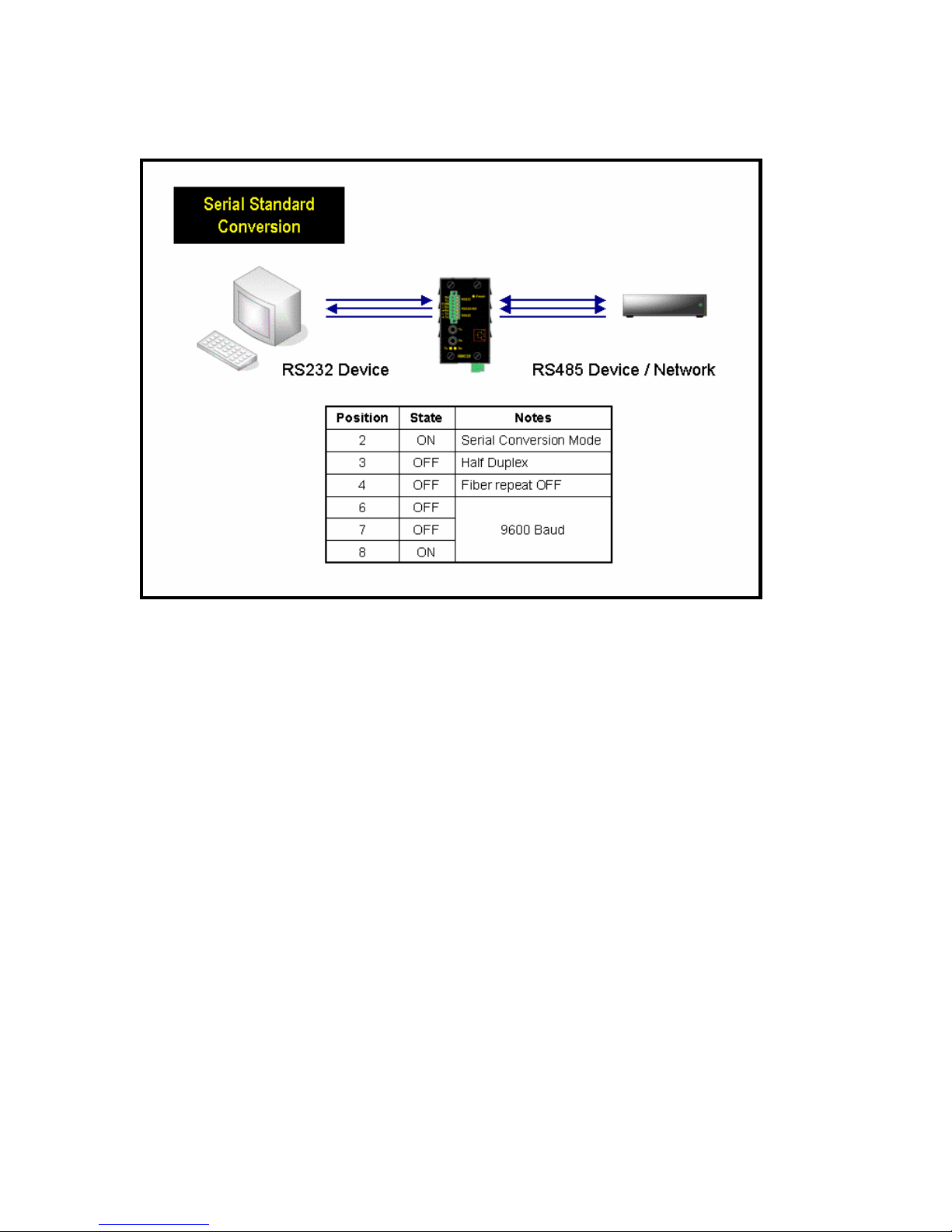
Figure 2.5.3 In serial conversion mode, one can convert from RS232 to RS485 / RS422
Figure 2.5.3 illustrates the connections for conversion between RS232 and RS485 / 422 devices.
In this mode of operation, RS232 voltage levels are converted to the appropriate RS485 or RS422
signaling levels depending on the DIP switch configuration. In this mode of operation position 2 of
the DIPswitches must be in the ON position. Figure 2.5.3 illustrates a RS232 device, connected to
an RS485 device or network. Since RS485 requires automatic turn-around, position 3 must be set
to the OFF state, and position 6 – 8 of the DIP switches must reflect the proper operating baud
rate.
Note: In this mode of operation, no isolation is provided between RS232 device and the
RS485/422 network – both devices share the same common terminal. It should be noted
that the common terminal on RS232 devices are connected to ground. In some instances
(ie when connecting to large RS485 networks), it may be preferential for the user to leave
the RS485/RS422 shield terminal unconnected to the RMC20 in this mode.
© 2006 RuggedCom Inc. All rights reserved Rev100
15
Page 16
2.5.3 Serial-to-Fiber Conversion: Loop Topology
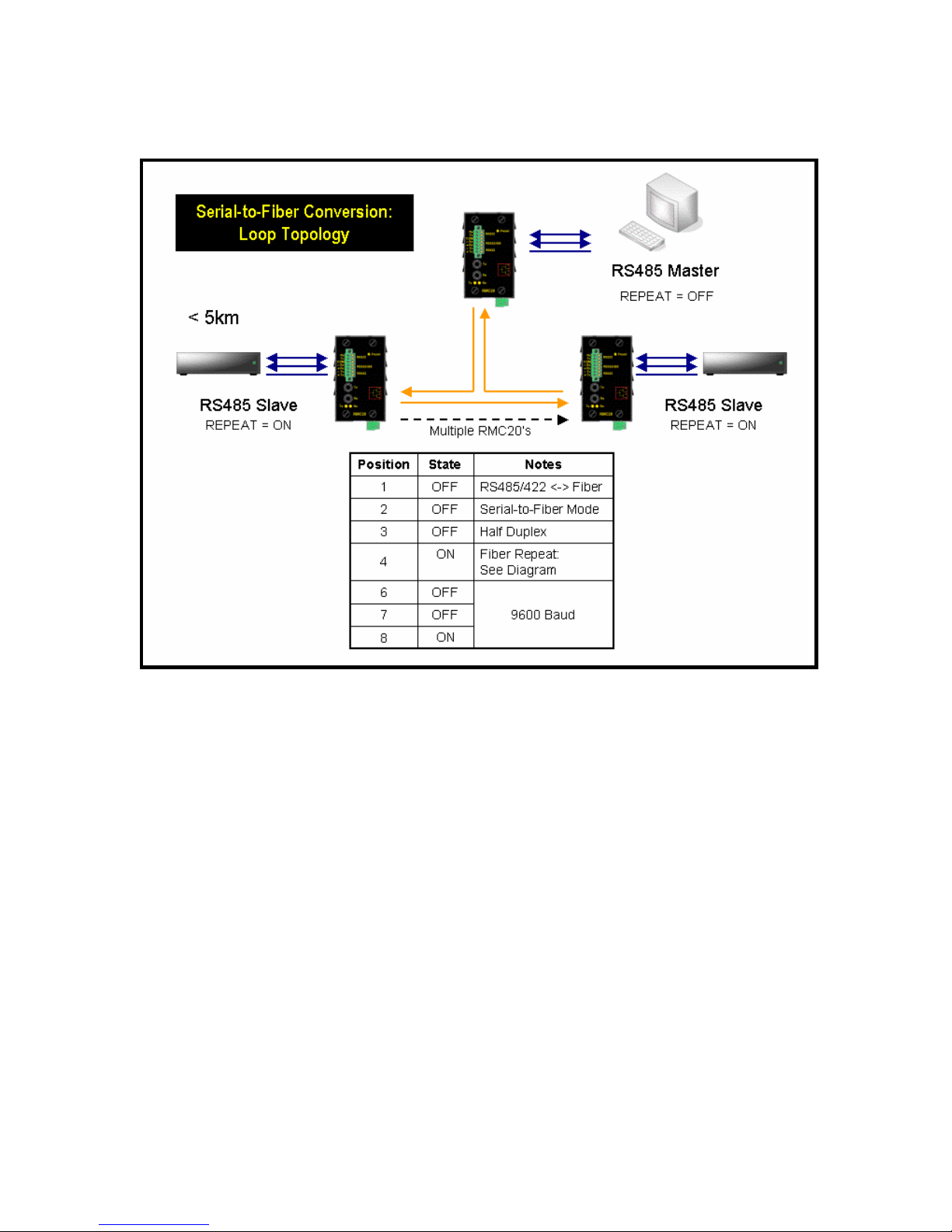
Figure 2.5.4 Serial-to-fiber conversion in example optical loop topology
Figure 2.5.4 illustrates the optical loop topology that utilizes the RMC20 repeat mode function. The
repeat function will optically re-transmit any data received on the optical receiver, in addition to any
connected serial devices. As a result, any data transmitted from the master, will be re-transmitted
optically to all the slaves. This mode of operation requires that the master device tolerate receiving
echoes of transmitted data since any transmissions will be received once again via the optical ring.
This topology can be used for RS232, RS485, or RS422 multi-drop networks. In all cases, all
slaves have the repeat function (DIP position 4) ON, while the master is configured with the repeat
function OFF. This topology can allow for the mixture of RS232, RS485, and RS422 devices,
operating on the same baud rate, on a single optical serial network because the RMC20 utilizes a
common optical signaling protocol for all serial standards.
© 2006 RuggedCom Inc. All rights reserved Rev100
16
Page 17
3 Specifications
3.1 Power Supply Specifications
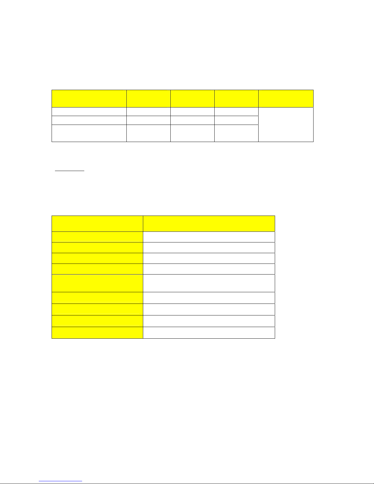
Power Supply Type Minimum
Input
24 VDC 18 VDC 36 VDC 3.15A(T) 2
48 VDC 36 VDC 72 VDC 3.15A(T) 2
HI (88/300 VDC) 1
1
HI (120/240 VAC)
Notes: 1 – This is the same power supply for both AC and DC.
2 – (T) Denotes time-delay fuse
88 VDC
85 VAC
CAUTION: For continued protection against risk of fire, replace only with same type and rating of
fuse.
3.2 Fiber Optical Port Specifications
Parameter Specifications
Maximum
Input
300 VDC
264 VAC
Fuse
Rating
3.15A(T)
Maximum Power
Consumption
2
3 W
Mode Multimode
Connector ST
Typical Dist. (km) 5
Optical Wavelength (nm) 820
Cable Size
Core/Cladding (um)
50/125
62.5/125
Tx Power (dBm) -13
Rx Sensitivity (dBm) -33.5
Rx Saturation (dBm) -11
Typical Budget (dB) 17.5
Notes:
1. Maximum segment length is greatly dependent on factors such as fiber quality, and
number of patches and splices. Please consult RuggedCom sales associates when
determining maximum segment distances.
2. All optical power numbers are listed as dBm averages.
© 2006 RuggedCom Inc. All rights reserved Rev100
17
Page 18
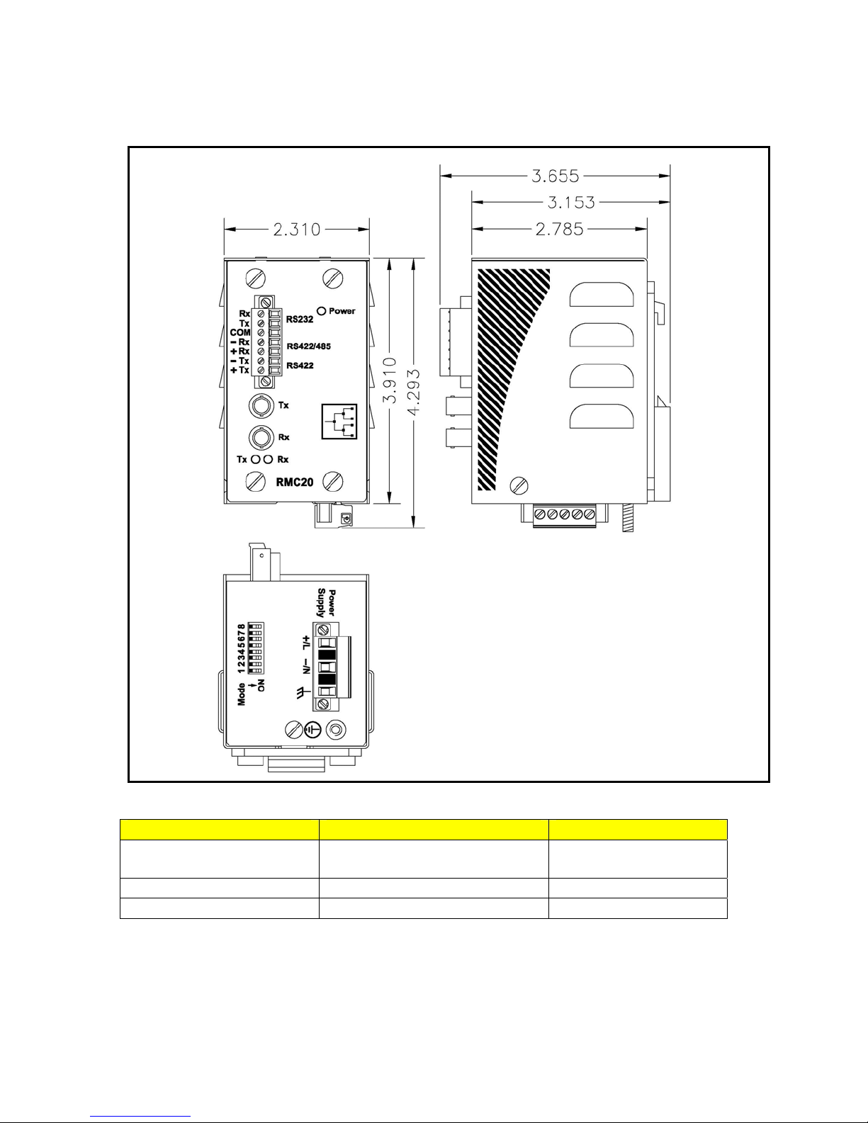
3.3 Mechanical Specifications
Parameter Value Comments
Dimensions
Weight 1.5 lb (0,68 Kg)
Enclosure 18 gauge Galvanized Steel
© 2006 RuggedCom Inc. All rights reserved Rev100
4.30 x 2.40 x 3.30 inches
(110) x (61) x (84) mm
18
(Length x Width x Height)
Page 19

4 Type Test Specifications
Electrical Safety Levels Comments
Dielectric Withstand 2 kV rms for 1 minute ANSI/IEEE C37.90 (1989)
IEC 60255-5 (Section 6)
High Voltage Impulse 5 kV peak IEC 60255-5 (Section 8)
Insulation Resistance 500 VDC for 1 minute IEC 60255-5 (Section 6
Electrical Environment Levels Comments
High Frequency Disturbance
(Oscillatory)
IEC Surge 4 kV / 2 kV
IEC Fast Transient 2 kV / 1 kV
ANSI/IEEE Fast Transient 4 kV ANSI/IEEE C37.90.1
IEC Radiated RFI Immunity 10 V/m IEC 61000-4-3
ANSI/IEEE Radiated RFI
Immunity
ESD
(Electrostatic Discharge)
Atmospheric Environment Levels Comments
Temperature (Dry Cold)
Temperature (Dry Heat)
Humidity
2.5 kV @ 1MHz for 2s
35 V/m ANSI/IEEE C37.90.2
15 kV (air discharge)
8 kV (contact)
-40°C
85°C
95%
Non-condensing
Test Ad: 16 hrs @ -40°C
Test Db: 6 cycles, 55°C, 95%
ANSI/IEEE C37.90.1
IEC 60255-22-1
IEC 61000-4-5
(Level 4)
IEC 61000-4-4
(Level 4)
IEC 61000-4-2
(Level 4)
IEC 60068-2-1
IEC 60068-2-2
Test Bd: 16 hrs @ 85°C
IEC 60068-2-30
Humidity
© 2006 RuggedCom Inc. All rights reserved Rev100
19
Page 20

4.1 Operating Environment
Parameter Range Comments
Ambient Operating
Temperature
Ambient Relative Humidity 5% to 95% Non-condensing
Ambient Storage
Temperature
-40 to 85°C
-40 to 85°C
Ambient Temperature as measured
from a 30cm radius surrounding the
center of the RuggedMC
4.2 Agency Approvals
Agency Standards Comments
CSA, CE CSA C22.2 No. 60950, UL 60950,
EN 60950
EN 61000-6-2
FCC FCC Part 15, Class A
CISPR EN55022, Class A Approved
FDA/CDRH 21 CFR Chapter 1, Subchapter J Compliant
IEC/EN
EN60825-1:1994 + A11:1996 +
A2:2001
Approved
Approved
Compliant
TM
enclosure.
5 Warranty
RuggedCom warrants this product for a period of five (5) years from date of purchase. For
warranty details, visit
Should this product require warranty or service contact the factory at:
RuggedCom Inc.
30 Whitmore Road
Woodbridge, Ontario
Canada L4L 7Z4
Phone: (905) 856-5288
Fax: (905) 856-1995
© 2006 RuggedCom Inc. All rights reserved Rev100
http://www.ruggedcom.com/ or contact your customer service representative.
20
 Loading...