

Page 1

v2.2 Web Interface User Guide
For RuggedBackbone™ RX1500
November 24, 2011
Page 2

ROX™
ROX™: Web Interface User Guide
Copyright © 2011 RuggedCom Inc.
ALL RIGHTS RESERVED
Dissemination or reproduction of this document, or evaluation and communication of its contents, is not authorized except where
expressly permitted. Violations are liable for damages. All rights reserved, particularly for the purposes of patent application or
trademark registration.
This document contains proprietary information, which is protected by copyright. All rights are reserved. No part of this document may
be photocopied, reproduced or translated to another language without the prior written consent of RuggedCom Inc.
Disclaimer Of Liability
We have checked the contents of this manual against the hardware and software described. However, deviations from the description
cannot be completely ruled out.
RuggedCom shall not be liable for any errors or omissions contained herein or for consequential damages in connection with the
furnishing, performance, or use of this material.
The information given in this document is reviewed regularly and any necessary corrections will be included in subsequent editions.
We appreciate any suggested improvements. We reserve the right to make technical improvements without notice.
Registered Trademarks
RuggedServer™, RuggedWireless™, RuggedCom Discovery Protocol™ (RCDP™), RuggedExplorer™, Enhanced Rapid Spanning
Tree Protocol™ (eRSTP™), ROX™, Rugged Operating System On Linux™, RuggedBackbone™ are trademarks of RuggedCom Inc.
Rugged Operating System® (ROS®) and RuggedSwitch® are registered trademarks of RuggedCom Inc. Other designations in this
manual might be trademarks whose use by third parties for their own purposes would infringe the rights of the owner.
Warranty
Five (5) years from date of purchase, return to factory. For warranty details, visit www.ruggedcom.com or contact your customer
service representative.
Contacting RuggedCom
Corporate Headquarters US Headquarters Europe Headquarters
RuggedCom Inc.
300 Applewood Crescent
Concord, Ontario
Canada, L4K 5C7
Tel: +1 905 856 5288
Fax: +1 905 856 1995
Toll-free: 1 888 264 0006
Technical Support
Toll Free (North America): 1 866 922 7975
International: +1 905 856 5288
Email: Support@RuggedCom.com
Web: www.RuggedCom.com
RuggedCom
1930 Harrison St., Suite 209
Hollywood, Florida
USA, 33020
Tel: +1 954 922 7938 ext. 103
Fax: +1 954 922 7984
Toll-free: 1 888 264 0006
Email: RuggedSales@RuggedCom.com
RuggedCom
Unit 41, Aztec Centre,
Aztec West, Almondsbury, Bristol
United Kingdom BS32 4TD
Tel: +44 1454 203 404
Fax: +44 1454 203 403
Page 3

ROX™
Table of Contents
Preface .................................................................................................................................... 25
Supported Platforms ........................................................................................................ 25
Who Should Use This User Guide .................................................................................... 25
How This Guide Is Organized ........................................................................................... 25
Applicable Operating System Software Revision ................................................................ 25
I. Administration ....................................................................................................................... 26
1. The ROX™ Web Interface ........................................................................................... 27
1.1. Getting Started .................................................................................................. 27
1.1.1. Requirements ......................................................................................... 27
1.1.2. Connecting To The Web Interface ........................................................... 27
1.1.3. The Web Browser Connection ................................................................. 27
1.2. The Structure Of The Web Interface ................................................................... 28
1.2.1. Top-level Menu Categories ..................................................................... 30
1.3. Making Configuration Changes .......................................................................... 31
1.3.1. Configuring Tables Using Key Settings Forms .......................................... 33
1.3.2. Viewing More Information in Tables ......................................................... 35
2. System Administration .................................................................................................. 37
2.1. Administration menu .......................................................................................... 37
2.2. System Commands ........................................................................................... 37
2.3. Administrative Access Control ............................................................................ 41
2.4. User Accounts .................................................................................................. 45
2.5. Software Upgrade ............................................................................................. 47
2.6. ROXflash Cross-Partition Imaging Tool - Software Downgrade ............................. 50
2.6.1. Uses ...................................................................................................... 50
2.6.2. ROXflash Configuration ........................................................................... 50
2.7. Scheduling Jobs ................................................................................................ 52
2.8. The Featurekey ................................................................................................. 55
2.8.1. Overview ................................................................................................ 55
2.8.2. Upgrading Feature Levels in the field ....................................................... 55
2.8.3. When a File-based featurekey does not Match the Hardware ..................... 55
2.8.4. Viewing RuggedCom Serial Numbers ...................................................... 56
2.8.5. Uploading a Featurekey .......................................................................... 57
2.8.6. Backing Up a Featurekey Using the Web User Interface ............................ 58
2.9. Installing and Backing Up Files .......................................................................... 59
2.9.1. Installing Files ........................................................................................ 59
2.9.2. Backing Up Files .................................................................................... 60
2.10. Deleting Log Files ........................................................................................... 61
2.11. Saving Full Configurations ............................................................................... 61
2.12. Loading Full Configurations .............................................................................. 62
3. Time Synchronization ................................................................................................... 63
3.1. NTP Fundamentals .......................................................................................... 63
3.1.1. The NTP Sanity Limit ............................................................................ 63
3.2. Configuring Time Synchronization ...................................................................... 64
3.2.1. Configuring the System Time and Date .................................................... 64
3.2.2. Configuring the System Time Zone .......................................................... 64
3.2.3. Configuring the Local Time Settings ........................................................ 65
3.2.4. Configuring NTP Servers ........................................................................ 65
3.2.5. Adding Server Keys ................................................................................ 67
3.2.6. Configuring NTP Server Restrictions ........................................................ 67
3.2.7. Configuring an NTP Server using Multicast or Broadcast ........................... 69
3.2.8. Configuring an NTP Client using Multicast ................................................ 70
ROX™ v2.2 User Guide 3 RuggedBackbone™ RX1500
Page 4

ROX™
3.2.9. Configuring an NTP Client using Broadcast .............................................. 70
3.2.10. Checking NTP Status ........................................................................... 71
4. Basic Network Configuration ......................................................................................... 72
4.1. IP Interfaces ..................................................................................................... 72
4.1.1. Configuring an IP Address ...................................................................... 72
4.1.2. Simple Network Setup with the Default IPv4 Addresses ............................. 73
4.1.3. Configuring an IPv6 Address ................................................................... 74
4.1.4. Simple Network Setup with IPv6 Addresses ............................................. 75
4.1.5. Routable Interfaces ................................................................................. 76
5. IP Network Interfaces ................................................................................................... 77
5.1. IPv6 Fundamentals ........................................................................................... 77
5.1.1. Addressing ............................................................................................. 77
5.1.2. Security ................................................................................................. 77
5.1.3. IPv6 Address Scopes ............................................................................. 77
5.1.4. IPv6 Multicast Addresses ........................................................................ 77
5.2. IPv6 Neighbor Discovery ................................................................................... 78
5.3. Adding Interfaces to Switched Ports ................................................................... 81
5.3.1. All-VLANs .............................................................................................. 83
5.4. Non-switched Interface Menu ............................................................................. 85
5.4.1. Configuring IP Address Source and ProxyARP for Non-switched
Interfaces ........................................................................................................ 87
6. Alarms ......................................................................................................................... 89
6.1. Introduction ....................................................................................................... 89
6.1.1. Alarm Subsystems .................................................................................. 89
6.1.2. Fail-Relay Behavior ................................................................................ 89
6.1.3. Alarm LED Behavior ............................................................................... 89
6.1.4. Clearing and Acknowledging Alarms ........................................................ 89
6.2. Alarm Configuration ........................................................................................... 90
6.2.1. Administrative Alarm Configuration .......................................................... 93
6.2.2. Chassis Alarm Configuration ................................................................... 94
6.2.3. Switch Alarm Configuration ..................................................................... 95
7. Domain Name Search .................................................................................................. 96
7.1. Domain Name Lookup ....................................................................................... 96
8. Logging ....................................................................................................................... 97
8.1. Configuring Local Syslog ................................................................................... 97
8.2. Configuring the Remote Syslog Server ............................................................... 97
8.3. Deleting Logs .................................................................................................. 100
9. SNMP ........................................................................................................................ 101
9.1. SNMP Traps ................................................................................................... 101
9.2. SNMP Access Configuration ............................................................................ 103
9.2.1. Add an SNMP User ID ......................................................................... 103
9.2.2. Create an SNMP Community ................................................................ 104
9.2.3. Map the Community to a Security Group ................................................ 105
9.3. SNMP menu ................................................................................................... 105
9.4. SNMP Discovery ............................................................................................. 109
9.5. SNMP Community ........................................................................................... 109
9.6. SNMP Target Addresses ................................................................................. 110
9.7. SNMP Users ................................................................................................... 112
9.8. SNMP Security to Group Maps ........................................................................ 114
9.9. SNMP Access ................................................................................................. 114
10. Authentication .......................................................................................................... 117
10.1. RADIUS ........................................................................................................ 117
10.1.1. RADIUS overview ............................................................................... 117
10.1.2. RADIUS Usage ................................................................................... 117
ROX™ v2.2 User Guide 4 RuggedBackbone™ RX1500
Page 5

ROX™
10.1.3. RADIUS on ROX™ ............................................................................. 118
10.1.4. RADIUS, ROX™, and Services ........................................................... 118
10.1.5. RADIUS Authentication Configuration ................................................... 118
11. NETCONF ............................................................................................................... 121
12. Chassis Management ............................................................................................... 125
12.1. Power Controller ............................................................................................ 126
12.2. Slot Hardware ............................................................................................... 127
12.3. Slot Identification ........................................................................................... 128
12.4. CPU .............................................................................................................. 129
12.5. Slot Status .................................................................................................... 130
12.6. Slot Sensors ................................................................................................. 131
12.7. Module Configuration ..................................................................................... 132
13. PPP Users ............................................................................................................... 135
13.1. Overview ....................................................................................................... 135
13.2. PPP Configuration ......................................................................................... 135
13.3. PPP Interfaces and Link Failover .................................................................... 138
14. DHCP Relay ............................................................................................................ 140
15. DHCP Server ........................................................................................................... 142
15.1. DHCP Fundamentals .................................................................................... 142
15.1.1. DHCP Network Organizations .............................................................. 142
15.1.2. Option 82 Support with Disable NAK .................................................... 142
15.2. Configuring DHCP Server .............................................................................. 143
15.2.1. Enabling the DHCP Service ................................................................. 143
15.2.2. DHCP Interfaces ................................................................................. 143
15.2.3. DHCP Subnets and Pools ................................................................... 144
15.2.4. DHCP Shared Networks ...................................................................... 145
15.2.5. DHCP Hosts ....................................................................................... 145
15.2.6. DHCP Host-groups ............................................................................. 146
15.2.7. Viewing Active DHCP Leases .............................................................. 146
15.2.8. DHCP Options .................................................................................... 147
15.2.9. Custom DHCP Options ....................................................................... 152
15.2.10. Hardware Configuration ..................................................................... 152
II. Network Interfaces and Ethernet Bridging ........................................................................... 154
16. Ethernet Ports .......................................................................................................... 155
16.1. Controller Protection Through Link-Fault-Indication (LFI) ................................. 155
16.2. Ethernet Port Configuration ........................................................................... 156
16.2.1. Port Parameters ................................................................................. 157
16.2.2. Port Rate Limiting .............................................................................. 159
16.2.3. Port Mirroring .................................................................................... 160
16.2.4. Diagnostics ....................................................................................... 162
16.2.5. Link Detection Options ....................................................................... 167
16.3. Port Status .................................................................................................... 168
16.4. Resetting Ports ............................................................................................ 170
16.4.1. Resetting All Switched Ports ................................................................ 171
16.5. Troubleshooting ............................................................................................ 171
17. Ethernet Statistics .................................................................................................... 173
17.1. Viewing Ethernet Statistics ............................................................................. 173
17.2. Viewing Ethernet Port Statistics ...................................................................... 173
17.3. Viewing Non-switched Ethernet Statistics ........................................................ 178
17.4. Clearing Switched Ethernet Port Statistics ....................................................... 181
18. IP Statistics .............................................................................................................. 183
19. Virtual Switch Bridging .............................................................................................. 186
19.1. Overview ....................................................................................................... 186
19.1.1. Helpful Hints ....................................................................................... 186
ROX™ v2.2 User Guide 5 RuggedBackbone™ RX1500
Page 6

ROX™
19.2. Sample Use Case ......................................................................................... 187
19.3. Virtual Switch Configuration and Status .......................................................... 188
20. Link Aggregation ...................................................................................................... 194
20.1. Link Aggregation Operation ............................................................................ 194
20.1.1. Link Aggregation Rules ....................................................................... 194
20.1.2. Link Aggregation Limitations ................................................................ 195
20.2. Link Aggregation Configuration ....................................................................... 196
20.2.1. Configuring Port Trunks ...................................................................... 196
21. Modem .................................................................................................................... 203
21.1. PPP and the Cellular Modem ......................................................................... 203
21.1.1. PPP and Cellular Modem Fundamentals .............................................. 203
21.1.2. PPP Cellular Modem Information and Configuration .............................. 203
22. Serial Protocols ...................................................................................................... 218
22.1. Introduction ................................................................................................... 218
22.1.1. Serial IP Port Features ........................................................................ 218
22.1.2. Serial Protocols Applications ................................................................ 219
22.1.3. Serial Protocols Concepts And Issues .................................................. 220
22.1.4. TcpModBus Server Application ............................................................ 221
22.1.5. TcpModbus Concepts And Issues ........................................................ 221
22.1.6. DNP (Distributed Network Protocol) ..................................................... 224
22.2. Serial Protocol Configuration .......................................................................... 225
22.2.1. Assigning Protocols ............................................................................. 225
22.2.2. Setting Rawsockets ............................................................................. 228
22.2.3. Setting TcpModbus ............................................................................. 229
22.2.4. Setting DNP ....................................................................................... 231
22.3. Serial Protocol Statistics ................................................................................ 232
22.3.1. Transport Connections ........................................................................ 234
22.4. Restarting the Serial Server ........................................................................... 236
22.5. Resetting Ports .............................................................................................. 236
23. WAN ........................................................................................................................ 237
23.1. T1/E1 Fundamentals ...................................................................................... 237
23.1.1. Frame Relay ..................................................................................... 237
23.1.2. RX1500 and Frame Relay Encapsulation ............................................. 237
23.2. WAN Configuration ........................................................................................ 238
23.2.1. T1 Parameters .................................................................................... 239
23.2.2. E1 Parameters ................................................................................... 240
23.2.3. Configuring Protocols .......................................................................... 240
23.2.4. Loopback Test .................................................................................... 248
23.3. Statistics ....................................................................................................... 249
23.3.1. Physical Layer-related Statistics ........................................................... 250
23.3.2. Protocol-related Statistics .................................................................... 255
23.3.3. Clearing Statistics ............................................................................... 261
23.4. DDS .............................................................................................................. 261
23.4.1. DDS Configuration .............................................................................. 262
23.4.2. Viewing and Clearing DDS Statistics .................................................... 266
24. Port Security ............................................................................................................ 268
24.1. Port Security Operation .................................................................................. 268
24.1.1. Static MAC address-based authorization .............................................. 268
24.1.2. IEEE 802.1X Authentication ................................................................. 268
24.2. Port Security Configuration ............................................................................. 270
24.2.1. Port Security Parameters .................................................................... 271
24.2.2. 802.1X Parameters ............................................................................. 272
25. Multicast Filtering ..................................................................................................... 274
25.1. IGMP ............................................................................................................ 274
ROX™ v2.2 User Guide 6 RuggedBackbone™ RX1500
Page 7

ROX™
25.1.1. Router and Host IGMP Operation ........................................................ 274
25.1.2. Switch IGMP Operation ....................................................................... 275
25.1.3. Combined Router and Switch IGMP Operation ...................................... 277
25.2. GMRP (GARP Multicast Registration Protocol) ................................................ 277
25.2.1. GMRP Example .................................................................................. 278
25.3. Multicast Filtering Configuration and Status .................................................... 280
25.3.1. Configuring IGMP Parameters ............................................................. 280
25.3.2. Configuring Static Multicast Groups ...................................................... 282
25.3.3. Configuring GMRP .............................................................................. 285
25.4. Troubleshooting ............................................................................................. 287
26. Classes Of Service .................................................................................................. 289
26.1. CoS Operation .............................................................................................. 289
26.1.1. Inspection Phase ................................................................................ 289
26.1.2. Forwarding Phase ............................................................................... 290
26.2. CoS Configuration ......................................................................................... 290
26.2.1. Global CoS Parameters ...................................................................... 290
26.2.2. Priority to CoS Mapping ...................................................................... 291
26.2.3. DSCP to CoS Mapping ....................................................................... 292
27. MAC Address Tables ............................................................................................... 294
28. Spanning Tree ......................................................................................................... 298
28.1. RSTP Operation ............................................................................................ 298
28.1.1. RSTP States and Roles ...................................................................... 299
28.1.2. Edge Ports ......................................................................................... 301
28.1.3. Point-to-Point and Multipoint Links ....................................................... 301
28.1.4. Path and Port Costs ........................................................................... 301
28.1.5. Bridge Diameter .................................................................................. 302
28.2. MSTP Operation ............................................................................................ 302
28.2.1. MST Regions and Interoperability ........................................................ 303
28.2.2. MSTP Bridge and Port Roles .............................................................. 304
28.2.3. Benefits of MSTP ............................................................................... 305
28.2.4. Implementing MSTP on a Bridged Network ........................................... 305
28.3. RSTP Applications ......................................................................................... 306
28.3.1. RSTP in Structured Wiring Configurations ............................................ 306
28.3.2. RSTP in Ring Backbone Configurations ............................................... 308
28.3.3. RSTP Port Redundancy ...................................................................... 309
28.4. Spanning Tree Configuration .......................................................................... 309
28.4.1. Spanning Tree Parameters .................................................................. 310
28.4.2. Port RSTP Parameters ........................................................................ 314
28.4.3. Bridge MSTI Parameters ..................................................................... 316
28.4.4. Port MSTI Parameters ........................................................................ 318
28.5. Spanning Tree Statistics ................................................................................ 320
28.5.1. Bridge RSTP Statistics ........................................................................ 320
28.5.2. Port RSTP Statistics ........................................................................... 322
28.5.3. MSTI Status ....................................................................................... 325
28.5.4. Port MSTP Statistics ........................................................................... 327
28.6. Clearing Spanning Tree Statistics ................................................................... 328
28.7. Troubleshooting ............................................................................................. 329
29. Virtual LANs ............................................................................................................. 332
29.1. VLAN Operation ............................................................................................ 332
29.1.1. VLANs and Tags ................................................................................ 332
29.1.2. Tagged vs. Untagged Frames ............................................................. 332
29.1.3. Native VLAN ....................................................................................... 332
29.1.4. Edge and Trunk Port Types ................................................................ 332
29.1.5. VLAN Ingress and Egress Rules .......................................................... 333
ROX™ v2.2 User Guide 7 RuggedBackbone™ RX1500
Page 8

ROX™
29.1.6. Forbidden Ports List ............................................................................ 333
29.1.7. VLAN-aware Mode of Operation .......................................................... 333
29.1.8. GVRP (GARP VLAN Registration Protocol) ......................................... 334
29.1.9. PVLAN Edge ..................................................................................... 335
29.2. VLAN Applications ......................................................................................... 336
29.2.1. Traffic Domain Isolation ....................................................................... 336
29.2.2. Administrative Convenience ................................................................. 336
29.2.3. Reduced Hardware ............................................................................. 336
29.3. VLAN Configuration ....................................................................................... 337
29.3.1. Static VLANs ...................................................................................... 338
29.3.2. Port VLAN Parameters ........................................................................ 339
29.3.3. VLAN Summary .................................................................................. 340
29.3.4. Forbidden Ports .................................................................................. 343
29.4. Troubleshooting ............................................................................................. 343
30. Network Discovery .................................................................................................. 345
30.1. LLDP Operation ............................................................................................ 345
30.2. LLDP Parameters .......................................................................................... 346
III. Routing and Security ......................................................................................................... 353
31. ROX™ Routing Overview ......................................................................................... 354
31.1. IP Routing in ROX™ ..................................................................................... 354
31.2. Physical Ethernet Port Types in ROX™ .......................................................... 354
31.3. Routing ......................................................................................................... 354
31.3.1. Using VLAN Interfaces for Routing and Layer 3 Switching ..................... 354
31.3.2. Routing IP Packets ............................................................................. 355
32. Layer 3 Switching .................................................................................................... 356
32.1. Layer 3 Switching Fundamentals .................................................................... 356
32.1.1. What is a Layer 3 Switch? .................................................................. 356
32.1.2. Layer 3 Switch Forwarding table .......................................................... 356
32.1.3. Static Layer 3 Switching Rules ............................................................ 357
32.1.4. Dynamic Learning of Layer 3 Switching Rules ...................................... 357
32.1.5. Layer 3 Switch ARP table ................................................................... 357
32.1.6. Layer 3 Multicast Switching ................................................................. 358
32.1.7. Size of the Layer 3 Switch Forwarding Table ........................................ 358
32.1.8. Interaction with the Firewall ................................................................. 358
32.1.9. Sample Use Case ............................................................................... 359
32.2. Configuring Layer 3 Switching ........................................................................ 362
32.2.1. Configuring Layer 3 Switching Settings ................................................ 363
32.2.2. Creating Static ARP Table Entries ....................................................... 364
32.2.3. Viewing Static and Dynamic ARP Table Entries .................................... 365
32.2.4. Viewing Routing Rules ........................................................................ 365
32.2.5. Flushing Dynamic Hardware Routing Rules .......................................... 368
33. Tunnelling ................................................................................................................ 369
33.1. IPsec ............................................................................................................ 369
33.1.1. VPN Fundamentals ............................................................................. 369
33.1.2. IPsec Configuration ............................................................................. 372
33.2. L2TP Tunnelling Configuration ....................................................................... 382
33.3. Layer 2 Tunnelling ......................................................................................... 384
33.3.1. IEC61850 GOOSE Fundamentals ........................................................ 384
33.3.2. Generic Layer 2 Tunnel Fundamentals ................................................. 385
33.3.3. Layer 2 Tunnelling Configuration ......................................................... 386
33.4. Generic Routing Encapsulation (GRE) ............................................................ 394
33.4.1. Generic Routing Encapsulation Configuration ....................................... 394
34. Dynamic Routing ...................................................................................................... 397
34.1. Introduction ................................................................................................... 397
ROX™ v2.2 User Guide 8 RuggedBackbone™ RX1500
Page 9

ROX™
34.1.1. RIP, OSPF, and BGP ........................................................................ 397
34.1.2. RIP Fundamentals ............................................................................. 397
34.1.3. OSPF Fundamentals ......................................................................... 397
34.1.4. Key OSPF And RIP Parameters .......................................................... 398
34.1.5. OSPF And VRRP Example Network .................................................... 400
34.1.6. BGP Fundamentals ............................................................................. 402
34.2. Dynamic Routing Configuration ...................................................................... 402
34.3. RIP ............................................................................................................... 402
34.3.1. RIP Configuration .............................................................................. 403
34.4. OSPF ........................................................................................................... 408
34.4.1. OSPF Configuration ............................................................................ 409
34.5. BGP ............................................................................................................. 413
34.5.1. BGP configuration ............................................................................... 413
35. Static Routing .......................................................................................................... 420
36. Routing Status ......................................................................................................... 422
36.1. IPv4 .............................................................................................................. 422
36.2. IPv6 .............................................................................................................. 423
36.3. Memory Statistics .......................................................................................... 423
36.4. RIP ............................................................................................................... 425
36.5. OSPF ........................................................................................................... 426
36.6. BGP ............................................................................................................. 430
37. Multicast Routing ...................................................................................................... 433
38. Firewall .................................................................................................................... 437
38.1. Firewall Fundamentals ................................................................................... 437
38.1.1. Stateless vs Stateful Firewalls ............................................................. 437
38.1.2. Linux® netfilter, iptables, and the Firewall ............................................. 437
38.1.3. Network Address Translation ............................................................... 437
38.1.4. Port Forwarding .................................................................................. 438
38.2. Firewall Quick Setup ...................................................................................... 438
38.3. Firewall Terminology And Concepts ................................................................ 439
38.3.1. Zones ................................................................................................. 439
38.3.2. Interfaces ........................................................................................... 439
38.3.3. Hosts ................................................................................................. 440
38.3.4. Policy ................................................................................................. 440
38.3.5. Masquerading and SNAT .................................................................... 441
38.3.6. Rules ................................................................................................. 442
38.4. Configuring The Firewall And VPN ................................................................. 443
38.4.1. Policy-based Virtual Private Networking ................................................ 443
38.4.2. Virtual Private Networking to a DMZ .................................................... 444
38.5. Firewall Configuration .................................................................................... 444
38.5.1. Adding a Firewall ................................................................................ 445
38.5.2. Working with Firewall Configurations .................................................... 446
38.5.3. Zone Configuration ............................................................................. 447
38.5.4. Interface Configuration ........................................................................ 448
38.5.5. Host Configuration .............................................................................. 449
38.5.6. Policies .............................................................................................. 450
38.5.7. Network Address Translation ............................................................... 451
38.5.8. IP Masquerading ................................................................................. 452
38.5.9. Rules ................................................................................................. 453
39. Traffic Control ......................................................................................................... 457
39.1. Traffic Control Modes .................................................................................... 457
39.1.1. Traffic Control Basic (basic-configuration) Configuration Mode .............. 457
39.1.2. Traffic Control Advanced (advanced-configuration) Configuration Mode
....................................................................................................................... 457
ROX™ v2.2 User Guide 9 RuggedBackbone™ RX1500
Page 10

ROX™
39.2. Traffic Control Configuration ........................................................................... 459
39.2.1. Traffic Control Modes .......................................................................... 459
40. VRRP ...................................................................................................................... 476
40.1. VRRP Fundamentals ..................................................................................... 476
40.1.1. The Problem With Static Routing ......................................................... 476
40.1.2. The VRRP Solution ............................................................................. 476
40.1.3. VRRP Terminology ............................................................................. 476
40.2. VRRP Configuration ...................................................................................... 478
40.2.1. VRRP Status ...................................................................................... 481
41. Link Failover ............................................................................................................ 483
41.1. Path Failure Discovery .................................................................................. 483
41.2. Using Routing Protocols and the Default Route ............................................... 483
41.3. Configuring Link Failover ............................................................................... 483
41.3.1. Configuring the Link Failover Settings .................................................. 484
41.3.2. Setting a Link Failover Backup Interface ............................................... 485
41.3.3. Setting a Link Failover Ping Target ...................................................... 486
41.3.4. Link Backup On Demand .................................................................... 487
41.3.5. Viewing Link Failover Status ................................................................ 487
41.3.6. Viewing the Link Failover Log .............................................................. 488
41.3.7. Testing Link Failover ........................................................................... 488
IV. Appendices ....................................................................................................................... 490
A. Upgrading Software ................................................................................................... 491
A.1. Preparing The Software Upgrade ..................................................................... 491
A.2. Launching The Upgrade .................................................................................. 492
A.3. Monitoring The Software Upgrade .................................................................... 493
B. RADIUS Server Configuration .................................................................................... 497
B.1. PPP / CHAP and Windows IAS ....................................................................... 497
C. Setting Up An Upgrade Server ................................................................................... 498
C.1. Upgrade Server Requirements ......................................................................... 498
C.2. Initial Upgrade Server Setup ............................................................................ 498
C.3. Upgrading The Repository ............................................................................... 498
C.4. Setting Up The Routers .................................................................................. 499
C.5. Using Microsoft Internet Information Services (IIS) Manager 6.0 or Higher as a
ROX Upgrade Repository ....................................................................................... 499
D. Adding and Replacing Line Modules ........................................................................... 500
D.1. Shutting Down the Unit to Remove/Insert Modules ............................................ 500
D.2. Adding a Module to an Empty Slot .................................................................. 500
D.3. Swapping a Module with an Identical Backup Module ........................................ 500
D.4. Swapping a Module with a Different Type of Module ......................................... 500
D.5. Swapping a Module with a Different Type of Module ......................................... 501
E. GNU General Public License ...................................................................................... 502
E.1. Preamble ........................................................................................................ 502
E.2. TERMS AND CONDITIONS FOR COPYING, DISTRIBUTION AND
MODIFICATION ..................................................................................................... 503
E.2.1. Section 0 ............................................................................................. 503
E.2.2. Section 1 ............................................................................................. 503
E.2.3. Section 2 ............................................................................................. 503
E.2.4. Section 3 ............................................................................................. 504
E.2.5. Section 4 ............................................................................................. 504
E.2.6. Section 5 ............................................................................................. 504
E.2.7. Section 6 ............................................................................................. 504
E.2.8. Section 7 ............................................................................................. 505
E.2.9. Section 8 ............................................................................................. 505
E.2.10. Section 9 ........................................................................................... 505
ROX™ v2.2 User Guide 10 RuggedBackbone™ RX1500
Page 11

ROX™
E.2.11. Section 10 ......................................................................................... 505
E.2.12. NO WARRANTY Section 11 ............................................................... 506
E.2.13. Section 12 ......................................................................................... 506
E.3. How to Apply These Terms to Your New Programs ........................................... 506
ROX™ v2.2 User Guide 11 RuggedBackbone™ RX1500
Page 12

ROX™
List of Figures
1.1. The ROX™ Login Form .................................................................................................... 28
1.2. The ROX™ Web Interface ................................................................................................. 28
1.3. Top-level Menu ................................................................................................................. 30
1.4. Example of Edit Private Mode ........................................................................................... 32
1.5. Adding Key Information ..................................................................................................... 33
1.6. Key Information in a Table ................................................................................................ 34
1.7. Example of Key Settings 1 ................................................................................................ 34
1.8. Example of Key Settings 2 ................................................................................................ 35
1.9. First Table of Information .................................................................................................. 36
1.10. Second Table of Information ............................................................................................ 36
2.1. Administration menu .......................................................................................................... 37
2.2. Clear All Alarms Menu Action form .................................................................................... 37
2.3. Acknowledge All Alarms Menu Action form ......................................................................... 37
2.4. Shutdown the Device Menu Action form ............................................................................. 38
2.5. Reboot the Device Menu Action form ................................................................................. 38
2.6. Set New Time and Date form ............................................................................................ 38
2.7. Set Clock on Target Device form ....................................................................................... 38
2.8. Restore-factory-defaults Trigger Action form ....................................................................... 39
2.9. Administration form ........................................................................................................... 39
2.10. Hostname form ............................................................................................................... 39
2.11. Timezone form ................................................................................................................ 40
2.12. Setting the Timezone Form - in Edit Private Mode ............................................................. 40
2.13. Current System Time form ............................................................................................... 40
2.14. CLI Sessions form ........................................................................................................... 41
2.15. Idle-timeout field .............................................................................................................. 42
2.16. Session Limits form ......................................................................................................... 42
2.17. STFP Sessions form ....................................................................................................... 43
2.18. WWW Interface Sessions ................................................................................................ 44
2.19. Idle-timeout field .............................................................................................................. 45
2.20. Users menu .................................................................................................................... 45
2.21. Users table ..................................................................................................................... 45
2.22. Users form ...................................................................................................................... 46
2.23. Users Screen in Edit Private View .................................................................................... 46
2.24. Software-Upgrade menu .................................................................................................. 47
2.25. Upgrade Settings ............................................................................................................ 47
2.26. Upgrade Monitoring ......................................................................................................... 48
2.27. Launch Upgrade .............................................................................................................. 49
2.28. Decline Upgrade ............................................................................................................. 49
2.29. Rollback and Reboot ....................................................................................................... 49
2.30. ROX-Imaging menu ......................................................................................................... 50
2.31. ROXflash Monitoring form ................................................................................................ 51
2.32. ROXFlash menu .............................................................................................................. 51
2.33. ROXFlash forms .............................................................................................................. 52
2.34. Scheduler menu .............................................................................................................. 52
2.35. Scheduled-jobs table ....................................................................................................... 53
2.36. Scheduled Jobs Form ...................................................................................................... 53
2.37. CLI in the ROX™ Web Interface ...................................................................................... 56
2.38. Install Files forms ............................................................................................................ 57
2.39. Backup Files forms .......................................................................................................... 59
2.40. Administration menu ........................................................................................................ 59
2.41. Install Files forms ............................................................................................................ 60
ROX™ v2.2 User Guide 12 RuggedBackbone™ RX1500
Page 13

ROX™
2.42. Backup Files forms .......................................................................................................... 60
2.43. Delete-logs menu ............................................................................................................ 61
2.44. Delete Log Files form ...................................................................................................... 61
2.45. Save-full-configuration menu ............................................................................................ 61
2.46. Save Full Configuration forms .......................................................................................... 62
2.47. Load-full-configuration menu ............................................................................................ 62
2.48. Load Full Configuration forms .......................................................................................... 62
3.1. Set new Time and Date form ............................................................................................. 64
3.2. Timezone form .................................................................................................................. 65
3.3. Local Time Settings form ................................................................................................... 65
3.4. Network Time Protocol (NTP) Servers ................................................................................ 65
3.5. Network Time Protocol (NTP) Servers form ........................................................................ 66
3.6. Server Keys form .............................................................................................................. 67
3.7. Server Restrictions Key settings form ................................................................................. 68
3.8. Server Restrictions form .................................................................................................... 68
3.9. NTP Broadcast/Multicast Servers form ............................................................................... 69
3.10. NTP Multicast Clients form .............................................................................................. 70
3.11. Network Time Protocol (NTP) form ................................................................................... 70
3.12. NTP Service Status form ................................................................................................. 71
4.1. IP menu ........................................................................................................................... 72
4.2. Configuring an IP Address ................................................................................................. 73
4.3. Basic Network Setup Using the Default IPv4 Addresses ...................................................... 74
4.4. Simple IPv6 Network Setup ............................................................................................... 75
4.5. Routable Interfaces table ................................................................................................... 76
4.6. Routable Interfaces form ................................................................................................... 76
4.7. Addresses table ................................................................................................................ 76
4.8. Addresses form ................................................................................................................. 76
5.1. Neighbor Discovery form ................................................................................................... 79
5.2. Neighbor Discovery IPv6 Prefix .......................................................................................... 80
5.3. Neighbor Discovery IPv6 Prefix forms ................................................................................ 80
5.4. Explicitly Adding a VLAN Interface to a Switched Port ......................................................... 82
5.5. All VLANs table ................................................................................................................ 84
5.6. All VLANs Properties form ................................................................................................. 84
5.7. Non-switched Interface menu ............................................................................................. 85
5.8. Routable Ethernet Ports table ............................................................................................ 85
5.9. Routable Ethernet Ports form ............................................................................................ 85
5.10. Configuring Dynamic Address Source and ProxyARP ........................................................ 87
6.1. Alarms menu .................................................................................................................... 90
6.2. Active Alarms table ........................................................................................................... 90
6.3. Active Alarms Key Settings form ........................................................................................ 90
6.4. Active Alarms form ............................................................................................................ 91
6.5. Clear Alarm Menu Action form ........................................................................................... 92
6.6. Acknowledge Alarm Menu Action form ............................................................................... 92
6.7. Clear All Alarms Menu Action form .................................................................................... 92
6.8. Acknowledge All Alarms Menu Action form ......................................................................... 92
6.9. Admin Alarm Configuration table ........................................................................................ 93
6.10. Admin Alarm Configuration form ....................................................................................... 93
6.11. Chassis Alarm Configuration table .................................................................................... 94
6.12. Chassis Alarm Configuration form .................................................................................... 94
6.13. Switch Alarm Configuration table ...................................................................................... 95
6.14. Switch Alarm Configuration form ...................................................................................... 95
7.1. DNS menu ........................................................................................................................ 96
7.2. Domain Name Searches form ............................................................................................ 96
7.3. Domain Name Servers ...................................................................................................... 96
ROX™ v2.2 User Guide 13 RuggedBackbone™ RX1500
Page 14

ROX™
8.1. Logging menu ................................................................................................................... 97
8.2. Remote Server table ......................................................................................................... 97
8.3. Remote Server form .......................................................................................................... 98
8.4. Remote Server Selector table ............................................................................................ 98
8.5. Selector menu .................................................................................................................. 98
8.6. Remote Server Selector form ............................................................................................. 99
9.1. Adding an SNMP User ID ................................................................................................ 103
9.2. Creating an SNMP Community ........................................................................................ 104
9.3. Mapping the Community to a Security Group .................................................................... 105
9.4. SNMP menu ................................................................................................................... 105
9.5. SNMP Sessions form ...................................................................................................... 106
9.6. SNMP USM Statistics form .............................................................................................. 108
9.7. SNMP-Discover action ..................................................................................................... 109
9.8. SNMP Engine ID Discover forms ..................................................................................... 109
9.9. SNMPv1/v2c Community Configuration table .................................................................... 109
9.10. SNMPv1/v2c Community Configuration form ................................................................... 110
9.11. SNMP Target Configuration table ................................................................................... 110
9.12. SNMPv3 Target Configuration form ................................................................................ 111
9.13. SNMP User Configuration table ...................................................................................... 112
9.14. User Configuration Key Settings form ............................................................................. 113
9.15. SNMP User Configuration form ...................................................................................... 113
9.16. SNMP Security Model to Group Mapping table ................................................................ 114
9.17. Key Settings form .......................................................................................................... 114
9.18. SNMP Security Model to Group Mapping form ................................................................ 114
9.19. SNMP Group Access Configuration table ........................................................................ 115
9.20. Key Settings form .......................................................................................................... 115
9.21. SNMP Group Access Configuration form ........................................................................ 115
10.1. Authentication menu ...................................................................................................... 117
10.2. Primary RADIUS Server form ......................................................................................... 119
10.3. Secondary RADIUS Server form .................................................................................... 119
11.1. NETCONF menu ........................................................................................................... 121
11.2. NETCONF Sessions form .............................................................................................. 121
11.3. Idle-timeout field ............................................................................................................ 122
11.4. NETCONF State/Statistics form ...................................................................................... 123
12.1. Chassis menu ............................................................................................................... 125
12.2. Chassis Status form ...................................................................................................... 125
12.3. Power Controller form .................................................................................................... 126
12.4. Power Status table ........................................................................................................ 126
12.5. Power Status form ......................................................................................................... 126
12.6. Slot Hardware table ....................................................................................................... 127
12.7. Slot Hardware form ....................................................................................................... 127
12.8. Slot Identification table ................................................................................................... 128
12.9. Slot Identification form ................................................................................................... 128
12.10. Slot CPU/RAM Utilization table ..................................................................................... 129
12.11. Slot CPU/RAM Utilization form ..................................................................................... 129
12.12. Slot Status table .......................................................................................................... 130
12.13. Slot Status form .......................................................................................................... 130
12.14. Slot Sensors table ....................................................................................................... 131
12.15. Slot Sensors form ........................................................................................................ 131
12.16. Modules table .............................................................................................................. 132
12.17. Modules form .............................................................................................................. 132
12.18. Fixed Modules form ..................................................................................................... 133
12.19. Fixed Modules table .................................................................................................... 133
12.20. Module Database table ................................................................................................ 134
ROX™ v2.2 User Guide 14 RuggedBackbone™ RX1500
Page 15

ROX™
12.21. Module Database form ................................................................................................. 134
12.22. Configurable Modules table .......................................................................................... 134
12.23. Configurable Modules form .......................................................................................... 134
13.1. PPP menu .................................................................................................................... 135
13.2. Dial-in PPP Users table ................................................................................................. 135
13.3. Dial-in Users form ......................................................................................................... 136
13.4. Dial-out PPP Users table ............................................................................................... 136
13.5. PPP Configuration form ................................................................................................. 136
13.6. PPP Primary Radius Server form ................................................................................... 138
13.7. PPP Secondary Radius Server form ............................................................................... 138
14.1. DHCP Relay Agent Menu .............................................................................................. 140
14.2. DHCP Relay Agent Form ............................................................................................... 140
14.3. DHCP Relay Agent Client Ports table ............................................................................. 141
15.1. DHCP Server menu ....................................................................................................... 143
15.2. DHCP Server form ........................................................................................................ 143
15.3. Listen Interfaces table .................................................................................................... 144
15.4. Subnet Configuration table ............................................................................................. 144
15.5. Subnet Configuration form ............................................................................................. 144
15.6. IP Pool Configuration table ............................................................................................ 145
15.7. Shared Network Configuration table ............................................................................... 145
15.8. Host Configuration table ................................................................................................ 145
15.9. Host Group Configuration table ...................................................................................... 146
15.10. /services/dhcpserver/show-active-leases form ................................................................ 147
15.11. Lease Configuration form ............................................................................................. 148
15.12. Client Configuration form for Subnets and Shared Networks ........................................... 148
15.13. Client Configuration form for Hosts ............................................................................... 149
15.14. Client Configuration form for Host-groups ...................................................................... 149
15.15. Client Configuration form for DHCP Clients ................................................................... 150
15.16. NIS Configuration form ................................................................................................ 151
15.17. Netbios Configuration form ........................................................................................... 151
15.18. Setting a DHCP Custom Option ................................................................................... 152
15.19. Hardware Configuration form ........................................................................................ 152
16.1. Controller Protection Through LFI ................................................................................... 155
16.2. Ethernet Ports menu ...................................................................................................... 156
16.3. Switched Ethernet Ports table ........................................................................................ 157
16.4. Switched Ethernet Ports submenu .................................................................................. 157
16.5. Switched Ethernet Ports form ......................................................................................... 158
16.6. Rate Limiting form ......................................................................................................... 159
16.7. Port-Mirroring menu ....................................................................................................... 161
16.8. Port Mirror form ............................................................................................................. 161
16.9. Ingress Source Ports table ............................................................................................. 161
16.10. Egress Source Ports table ........................................................................................... 161
16.11. Diagnostics menu ........................................................................................................ 162
16.12. Cable Diagnostics Results form .................................................................................... 162
16.13. Start Cable Diagnostics Test form ................................................................................ 165
16.14. Start Cable Test form .................................................................................................. 165
16.15. Clear Port Cable Diagnostic Test Results form .............................................................. 165
16.16. Clear All Diagnostics (Switch) menu ............................................................................. 166
16.17. Clear All Cable Diagnostic Test Results form ................................................................ 166
16.18. Clear All Alarms menu ................................................................................................. 166
16.19. Clear All Active Alarms Trigger Action .......................................................................... 166
16.20. Switch (Link Detection) menu ....................................................................................... 167
16.21. Link Detection form ...................................................................................................... 167
16.22. Interfaces menu ........................................................................................................... 168
ROX™ v2.2 User Guide 15 RuggedBackbone™ RX1500
Page 16

ROX™
16.23. Interface Status table ................................................................................................... 169
16.24. Interface Status form ................................................................................................... 169
16.25. Port Security Status form ............................................................................................. 170
16.26. Reset Ethernet Port form ............................................................................................. 171
16.27. Reset All Switched Ports menu .................................................................................... 171
16.28. Reset All Switched Ports form ...................................................................................... 171
17.1. Ethernet Port Statistics Menu ......................................................................................... 173
17.2. Port Statistics Form ....................................................................................................... 173
17.3. RMON Port Statistics Form ............................................................................................ 175
17.4. Statistics Menu .............................................................................................................. 178
17.5. Routable-Only Ethernet Port Status Form ....................................................................... 179
17.6. Receive Statistics Form ................................................................................................. 180
17.7. Transmit Statistics Form ................................................................................................ 181
17.8. Interfaces Switch (Clearing Port Statistics) Menu ............................................................. 181
17.9. Clear Switched Port Statistics Form ................................................................................ 182
17.10. Clear All Statistics Menu .............................................................................................. 182
17.11. Clear All Switched Port Statistics Form ......................................................................... 182
18.1. Interfaces IP Menu ........................................................................................................ 183
18.2. Routable Interface Statistics Table ................................................................................. 183
18.3. Routable Interface Statistics Form .................................................................................. 183
18.4. Receive Statistics Form ................................................................................................. 184
18.5. Transmit Statistics Form ................................................................................................ 184
19.1. Virtual switch with multiple interfaces .............................................................................. 187
19.2. Adding a Virtual Switch .................................................................................................. 188
19.3. Interface Virtualswitch menu .......................................................................................... 188
19.4. Virtualswitch table .......................................................................................................... 188
19.5. Virtualswitch form .......................................................................................................... 189
19.6. Interface table ............................................................................................................... 189
19.7. VLAN table ................................................................................................................... 189
19.8. VLAN form .................................................................................................................... 190
19.9. Interfaces Virtualswitch menu ......................................................................................... 190
19.10. Virtualswitch table ........................................................................................................ 190
19.11. Virtualswitch form ........................................................................................................ 190
19.12. Receive form ............................................................................................................... 191
19.13. Transmit form .............................................................................................................. 191
19.14. VLAN table .................................................................................................................. 192
19.15. VLAN Receive form ..................................................................................................... 192
19.16. VLAN Transmit form .................................................................................................... 193
20.1. Link Aggregation Examples ............................................................................................ 194
20.2. Link Aggregation menu .................................................................................................. 196
20.3. Adding Trunks ............................................................................................................... 196
20.4. Entering a Trunk ID ....................................................................................................... 197
20.5. Entering Parameters for Forms ...................................................................................... 198
20.6. Trunk-Ports Submenu - Adding a Trunk-Port ................................................................... 199
20.7. Selecting a Trunk Slot ................................................................................................... 199
20.8. Trunk Ports table ........................................................................................................... 200
20.9. Trunk Ports Table in Edit Private Mode .......................................................................... 200
20.10. Key Settings ................................................................................................................ 200
20.11. Ethernet Trunk Interfaces form ..................................................................................... 200
20.12. Multicast Filtering form ................................................................................................. 200
20.13. CoS form .................................................................................................................... 201
20.14. VLAN form .................................................................................................................. 201
20.15. Trunk Ports table ......................................................................................................... 202
21.1. Interfaces Cellmodem menu ........................................................................................... 203
ROX™ v2.2 User Guide 16 RuggedBackbone™ RX1500
Page 17

ROX™
21.2. HSPA Cellular Modem Information form .......................................................................... 204
21.3. Edge Cellular Modem Information form ........................................................................... 205
21.4. Global Cellular GSM menu ............................................................................................ 206
21.5. GSM Cellular Network Configuration form ....................................................................... 207
21.6. PPP Configuration form ................................................................................................. 207
21.7. CDMA EVDO Cellular Modem Information form ............................................................... 208
21.8. CDMA Over The Air Activation form ............................................................................... 210
21.9. CDMA Over The Air Activation Trigger Action form .......................................................... 210
21.10. CDMA Manual Activation form ...................................................................................... 211
21.11. CDMA Manual Activation Trigger Action form ................................................................ 211
21.12. CDMA Reset Modem Trigger Action form ..................................................................... 211
21.13. Global Cellular CDMA menu ........................................................................................ 212
21.14. Cellular Network Configuration table ............................................................................. 212
21.15. Cellular Network Configuration form .............................................................................. 212
21.16. PPP Configuration form ............................................................................................... 213
21.17. Interface Cellmodem menu .......................................................................................... 213
21.18. Routable Cellular Modem Interfaces table ..................................................................... 214
21.19. Routable Cellular Modem Interfaces form ...................................................................... 214
21.20. Interface Cellmodem HSPA menu ................................................................................ 215
21.21. GSM Profile form ......................................................................................................... 215
21.22. Interfaces Cellmodem menu ......................................................................................... 215
21.23. Cellular Modem Interfaces table ................................................................................... 215
21.24. Interfaces Cellmodem HSPA menu ............................................................................... 216
21.25. Cellular Modem Interfaces form .................................................................................... 216
21.26. HSPA PPP Interfaces Statistics form ............................................................................ 216
22.1. 6S01 Serial Module RJ45 Connector LEDs ..................................................................... 218
22.2. Sources of Delay and Error in an End to End Exchange .................................................. 222
22.3. Serial Protocols menu .................................................................................................... 225
22.4. Serial Interfaces table .................................................................................................... 225
22.5. Adding a Protocol in the Edit Private screen ................................................................... 226
22.6. Selecting a Protocol Type in the Edit Private screen ........................................................ 226
22.7. Serial Ports Configuration form ....................................................................................... 227
22.8. Serial Protocols table ..................................................................................................... 228
22.9. Rawsocket Configuration form ........................................................................................ 228
22.10. TCP Modbus Configuration form ................................................................................... 229
22.11. DNP Protocols Configuration form ................................................................................ 231
22.12. DNP Device Address Table Configuration table ............................................................. 231
22.13. DNP Device Address Table Configuration form ............................................................. 231
22.14. Serial Protocol Statistics menu ..................................................................................... 232
22.15. Serial Port Statistics table ............................................................................................ 232
22.16. Serial Port Statistics form ............................................................................................. 233
22.17. Transport Connections Statistics table .......................................................................... 234
22.18. TCP/UDP Connection Statistics form ............................................................................ 235
22.19. Restart Serserver menu ............................................................................................... 236
22.20. Restart Serserver Trigger Action ................................................................................... 236
22.21. Reset Ports menu ........................................................................................................ 236
22.22. Reset Ports Trigger Action ........................................................................................... 236
23.1. WAN menu ................................................................................................................... 238
23.2. Interface WAN Slot Port Settings table ........................................................................... 238
23.3. Enable WAN Interface form ........................................................................................... 238
23.4. T1 Parameters form ...................................................................................................... 239
23.5. E1 Parameters form ...................................................................................................... 240
23.6. T1 Channels and Associated Time Slots table ................................................................ 241
23.7. T1 Time Slots form ........................................................................................................ 241
ROX™ v2.2 User Guide 17 RuggedBackbone™ RX1500
Page 18

ROX™
23.8. Adding a Connection ..................................................................................................... 242
23.9. Frame Relay Parameter form ......................................................................................... 242
23.10. Connection Frame Relay DLCI table ............................................................................. 243
23.11. Adding an MLPPP Connection ..................................................................................... 244
23.12. Adding IP and Remote Addresses ................................................................................ 245
23.13. HDLC-ETH menu ........................................................................................................ 246
23.14. Ethernet Over HDLC Settings form ............................................................................... 246
23.15. Adding a VLAN ........................................................................................................... 247
23.16. T1/E1 Interfaces under the IP submenu ........................................................................ 248
23.17. Loopback Test Forms .................................................................................................. 248
23.18. Loopbacktest Results ................................................................................................... 249
23.19. WAN Statistics menu ................................................................................................... 249
23.20. T1E1 Statistics table .................................................................................................... 249
23.21. Receiving Errors Statistics form .................................................................................... 250
23.22. T1E1 Receiving Statistics form ..................................................................................... 251
23.23. T1E1 Receiving Statistics Form 2 ................................................................................. 251
23.24. T1E1 Transmitting Errors Statistics form ....................................................................... 252
23.25. T1E1 Transmitting Statistics form ................................................................................. 252
23.26. T1E1 Transmitting Statistics Form 2 ............................................................................. 253
23.27. T1E1 Alarm Indication form .......................................................................................... 254
23.28. T1E1 Statistics form .................................................................................................... 255
23.29. PPP Receiving Protocol Statistics form ......................................................................... 255
23.30. PPP Transmitting Protocol Statistics form ..................................................................... 256
23.31. T1E1 Statistics form .................................................................................................... 256
23.32. Frame Relay Errors Packets Statistics form .................................................................. 258
23.33. Frame Relay Controlling Packets Statistics form ............................................................ 259
23.34. Frame Relay Receiving Statistics form .......................................................................... 260
23.35. Clear Interface Statistics Form And Trigger Action ......................................................... 261
23.36. Clearstatistics Menu Action .......................................................................................... 261
23.37. Enable Wan Interface form .......................................................................................... 262
23.38. DDS Parameters form .................................................................................................. 263
23.39. PPP form .................................................................................................................... 263
23.40. Frame Relay Parameters form ..................................................................................... 264
23.41. Loopback Test form ..................................................................................................... 265
23.42. DDS Statistics menu .................................................................................................... 266
23.43. Clear Interface Statistics form ....................................................................................... 267
24.1. 802.1X General Topology .............................................................................................. 269
24.2. 802.1X Packet Exchange ............................................................................................... 269
24.3. Port Security RADIUS Primary form ............................................................................... 270
24.4. Port Security RADIUS Secondary form ........................................................................... 270
24.5. Port Security menu ........................................................................................................ 271
24.6. Port Security form ......................................................................................................... 271
24.7. 802.1x Parameters form ................................................................................................ 272
25.1. IGMP Operation Example 1 ........................................................................................... 275
25.2. IGMP Operation Example 2 ........................................................................................... 277
25.3. Example using GMRP ................................................................................................... 279
25.4. Multicast Filtering menu ................................................................................................. 280
25.5. IGMP Snooping Parameters form ................................................................................... 281
25.6. Router Ports table ......................................................................................................... 281
25.7. Egress Ports table ......................................................................................................... 282
25.8. Static Multicast Summary table ...................................................................................... 282
25.9. Static Multicast Summary form ....................................................................................... 282
25.10. Static Ports table ......................................................................................................... 283
25.11. Static Ports form .......................................................................................................... 283
ROX™ v2.2 User Guide 18 RuggedBackbone™ RX1500
Page 19

ROX™
25.12. Multicast Group Summary table .................................................................................... 283
25.13. IP Multicast Groups table ............................................................................................. 284
25.14. IP Multicast Groups form ............................................................................................. 284
25.15. Router-Ports table ........................................................................................................ 284
25.16. Router-Ports form ........................................................................................................ 284
25.17. Joined-Ports table ........................................................................................................ 285
25.18. Joined-Ports form ........................................................................................................ 285
25.19. GMRP form ................................................................................................................. 285
25.20. GMRP Dynamic Ports table ......................................................................................... 286
25.21. GMRP Dynamic Ports form .......................................................................................... 286
25.22. Multicast Filtering form ................................................................................................. 286
26.1. Determining The CoS Of A Received Frame ................................................................... 290
26.2. Class-of-service menu ................................................................................................... 290
26.3. CoS form ...................................................................................................................... 290
26.4. Priority to CoS Mapping table ........................................................................................ 291
26.5. Priority to CoS Mapping form ......................................................................................... 291
26.6. TOS DSCP to CoS Mapping table .................................................................................. 292
26.7. TOS DSCP to CoS Mapping form .................................................................................. 292
26.8. CoS form ...................................................................................................................... 292
27.1. MAC Tables menu ........................................................................................................ 294
27.2. MAC Address table ....................................................................................................... 294
27.3. Mac Address form ......................................................................................................... 294
27.4. MAC Tables form .......................................................................................................... 295
27.5. Key Settings .................................................................................................................. 296
27.6. Static MAC Address Parameters form ............................................................................ 296
27.7. Static MAC Address Parameters table ............................................................................ 296
27.8. Purge MAC Address menu ............................................................................................ 297
27.9. Purge MAC Address Table form ..................................................................................... 297
28.1. Bridge and Port States .................................................................................................. 299
28.2. Bridge and Port Roles ................................................................................................... 300
28.3. Example of a Structured Wiring Configuration ................................................................. 307
28.4. Example of a Ring Backbone Configuration .................................................................... 308
28.5. Port Redundancy ........................................................................................................... 309
28.6. Spanning Tree menu ..................................................................................................... 310
28.7. Spanning Tree Parameter form ...................................................................................... 310
28.8. RSTP Common Instance form ........................................................................................ 312
28.9. eRSTP form .................................................................................................................. 312
28.10. Interface/switch/{line module}/spanning-tree submenu .................................................... 314
28.11. Port RSTP Parameter form .......................................................................................... 314
28.12. Key Settings form ........................................................................................................ 316
28.13. MSTP Instance form .................................................................................................... 316
28.14. MSTP Instance table ................................................................................................... 317
28.15. MSTP ID table ............................................................................................................ 317
28.16. MSTI Configuration table .............................................................................................. 318
28.17. MSTI Configuration form .............................................................................................. 318
28.18. RSTP Status form ....................................................................................................... 320
28.19. RSTP Port Statistics table ............................................................................................ 322
28.20. RSTP Port Statistics form ............................................................................................ 323
28.21. MSTI Status table ........................................................................................................ 325
28.22. MSTI Status form ........................................................................................................ 325
28.23. MSTP Port Statistics table ........................................................................................... 327
28.24. MSTP Port Statistics form ............................................................................................ 327
28.25. Clear-stp-stats Menu Action ......................................................................................... 328
28.26. Clear Spanning-Tree Statistics form .............................................................................. 329
ROX™ v2.2 User Guide 19 RuggedBackbone™ RX1500
Page 20

ROX™
29.1. Using GVRP ................................................................................................................. 335
29.2. Multiple Overlapping VLANs ........................................................................................... 336
29.3. Inter-VLAN Communications .......................................................................................... 337
29.4. Virtual LANs menu ........................................................................................................ 337
29.5. Internal VLAN Range form ............................................................................................. 338
29.6. Static VLAN table .......................................................................................................... 338
29.7. Static VLAN form .......................................................................................................... 338
29.8. Switched Ethernet Ports submenu .................................................................................. 339
29.9. VLAN Parameters form .................................................................................................. 339
29.10. VLAN Summary table .................................................................................................. 340
29.11. VLAN Summary form ................................................................................................... 341
29.12. Tagged Ports table ...................................................................................................... 341
29.13. Tagged Ports form ....................................................................................................... 341
29.14. Untagged Ports table ................................................................................................... 342
29.15. Untagged Ports form .................................................................................................... 342
29.16. All VLANs table ........................................................................................................... 342
29.17. All VLANs Properties form ........................................................................................... 342
29.18. VLANs table ................................................................................................................ 342
29.19. VLANs form ................................................................................................................ 343
29.20. Forbidden Ports ........................................................................................................... 343
30.1. Net-discovery menu ....................................................................................................... 345
30.2. Net-discovery LLDP menu ............................................................................................. 346
30.3. LLDP form .................................................................................................................... 346
30.4. LLDP Global Statistics form ........................................................................................... 347
30.5. LLDP Local System form ............................................................................................... 348
30.6. LLDP Port Statistics table .............................................................................................. 349
30.7. LLDP Port Statistics form ............................................................................................... 349
30.8. LLDP Neighbors table .................................................................................................... 350
30.9. LLDP Neighbors form .................................................................................................... 351
30.10. LLDP submenu ............................................................................................................ 351
30.11. LLDP form .................................................................................................................. 352
31.1. Three interfaces on an isolated VLAN ............................................................................ 354
31.2. VLAN connected to ROX device through switch.0100 ...................................................... 355
32.1. Layer 3 Switch .............................................................................................................. 356
32.2. Layer 3 Switch Use Case .............................................................................................. 359
32.3. Hardware Acceleration Enabled ..................................................................................... 360
32.4. Hardware Acceleration Enabled ..................................................................................... 360
32.5. Layer 3 Switching menu ................................................................................................ 362
32.6. Layer 3 Switching form .................................................................................................. 362
32.7. Layer 3 Switching form .................................................................................................. 363
32.8. ARP Table Configuration form ........................................................................................ 365
32.9. ARP Table Summary form ............................................................................................. 365
32.10. Routing Rules Summary table ...................................................................................... 366
32.11. Routing Rules Summary form ....................................................................................... 366
32.12. Flush Dynamic Hardware Routing Rules form ............................................................... 368
33.1. Tunnelling menu ............................................................................................................ 369
33.2. IPsec menu ................................................................................................................... 372
33.3. IPsec form .................................................................................................................... 372
33.4. Syslog form ................................................................................................................... 372
33.5. Show Public RSA Key form ........................................................................................... 373
33.6. Install-Certificate forms .................................................................................................. 374
33.7. Install-Ca-Certificate forms ............................................................................................. 375
33.8. Install-Crl-File forms ....................................................................................................... 376
33.9. Show IPsec Running Status form ................................................................................... 376
ROX™ v2.2 User Guide 20 RuggedBackbone™ RX1500
Page 21

ROX™
33.10. Connection table .......................................................................................................... 376
33.11. Connection form .......................................................................................................... 377
33.12. ESP table .................................................................................................................... 378
33.13. ESP Key Settings ........................................................................................................ 378
33.14. IKE table ..................................................................................................................... 378
33.15. Public IP Address form ................................................................................................ 379
33.16. System Public Key form ............................................................................................... 379
33.17. Nexthop To Other System form .................................................................................... 380
33.18. System Identifier form .................................................................................................. 380
33.19. Private Subnet Behind System form ............................................................................. 380
33.20. Network table .............................................................................................................. 381
33.21. Preshared Key table .................................................................................................... 381
33.22. Preshared Key form ..................................................................................................... 381
33.23. L2TP menu ................................................................................................................. 382
33.24. L2TP form ................................................................................................................... 382
33.25. DNS Server form ......................................................................................................... 382
33.26. PPP Options form ........................................................................................................ 383
33.27. WINS Server form ....................................................................................................... 383
33.28. L2tunneld menu ........................................................................................................... 386
33.29. L2 Tunnel Daemon form .............................................................................................. 386
33.30. Goose Tunnel table ..................................................................................................... 387
33.31. Goose Tunnel form ...................................................................................................... 387
33.32. Remote Daemon of Goose Tunnel table ....................................................................... 387
33.33. Generic L2 Tunnel table .............................................................................................. 387
33.34. Generic L2 Tunnel Protocol form .................................................................................. 388
33.35. Generic L2 Tunnel Egress Interface table ..................................................................... 388
33.36. L2 Ethernet Type table ................................................................................................ 388
33.37. Goose Tunnel Statistics table ....................................................................................... 388
33.38. Goose Tunnel Statistics form ....................................................................................... 389
33.39. Connections Statistics table .......................................................................................... 390
33.40. Connections Statistics form .......................................................................................... 390
33.41. Generic L2 Tunnel Statistics table ................................................................................ 391
33.42. Generic L2 Tunnel Statistics form ................................................................................. 391
33.43. Connections Statistics table .......................................................................................... 392
33.44. Connections Statistics form .......................................................................................... 392
33.45. Round Trip Time Statistics table ................................................................................... 393
33.46. Round Trip Time Statistics form ................................................................................... 393
33.47. GRE Example ............................................................................................................. 394
33.48. Generic Routing Encapsulation (GRE) menu ................................................................. 394
33.49. Generic Routing Encapsulation Interfaces table ............................................................. 395
33.50. Generic Routing Encapsulation Interfaces form ............................................................. 395
34.1. OSPF and VRRP Example ............................................................................................ 401
34.2. Dynamic Routing Menu .................................................................................................. 402
34.3. RIP Menu ..................................................................................................................... 402
34.4. RIP Configuration Form ................................................................................................. 403
34.5. Routing Timers Form ..................................................................................................... 404
34.6. RIP Interface Parameters Table ..................................................................................... 406
34.7. RIP Interface Parameters Form ...................................................................................... 407
34.8. Authentication Form ....................................................................................................... 407
34.9. OSPF Menu .................................................................................................................. 408
34.10. OSPF Configuration Form ............................................................................................ 409
34.11. OSPF Area Distance Form ........................................................................................... 410
34.12. Interface Parameters Table .......................................................................................... 411
34.13. Interface Parameters Form ........................................................................................... 411
ROX™ v2.2 User Guide 21 RuggedBackbone™ RX1500
Page 22

ROX™
34.14. Dead Interval Form ...................................................................................................... 412
34.15. BGP Menu .................................................................................................................. 413
34.16. BGP Configuration Form .............................................................................................. 413
34.17. Distance Form ............................................................................................................. 414
35.1. Static Menu ................................................................................................................... 420
35.2. Static Route table .......................................................................................................... 420
35.3. Static Route form .......................................................................................................... 420
35.4. Static Route Using Gateway table .................................................................................. 420
35.5. Static Route Using Gateway form ................................................................................... 420
35.6. Blackhole Static Route form ........................................................................................... 421
35.7. Static Route Using Interface table .................................................................................. 421
35.8. Static Route Using Interface form ................................................................................... 421
36.1. Routing Status Menu ..................................................................................................... 422
36.2. IPv4 Kernel Active Routing Table ................................................................................... 422
36.3. IPv6Kernel Active Routing Table .................................................................................... 423
36.4. Core Daemon Memory Statistics Form ........................................................................... 424
36.5. RIP Daemon Memory Statistics Form ............................................................................. 424
36.6. BGP Daemon Memory Statistics Form ............................................................................ 424
36.7. OSPF Daemon Memory Statistics Form .......................................................................... 425
36.8. RIP Menu ..................................................................................................................... 425
36.9. OSPF Menu .................................................................................................................. 426
36.10. Network Table ............................................................................................................. 426
36.11. Reach Table ................................................................................................................ 426
36.12. Router Table ............................................................................................................... 427
36.13. Area Table .................................................................................................................. 427
36.14. Net Table .................................................................................................................... 427
36.15. Summary Table ........................................................................................................... 428
36.16. ASBR-Summary Table ................................................................................................. 429
36.17. AS-External Table ........................................................................................................ 429
36.18. Neighbor Table ............................................................................................................ 430
36.19. BGP Menu .................................................................................................................. 430
36.20. Route Table ................................................................................................................ 431
36.21. Next Hop Table ........................................................................................................... 431
36.22. BGP Neighbor Table .................................................................................................... 432
37.1. Multicast Routing menu ................................................................................................. 433
37.2. Static Multicast Routing Configuration form ..................................................................... 433
37.3. Static menu ................................................................................................................... 433
37.4. Multicast Groups Configuration table .............................................................................. 433
37.5. Multicast Groups Configuration form ............................................................................... 434
37.6. Outgoing Interfaces table ............................................................................................... 434
37.7. Multicast Routing Status table ........................................................................................ 435
37.8. Multicast Routing Status form ......................................................................................... 435
38.1. Security Menu ............................................................................................................... 444
38.2. Firewall Description table ............................................................................................... 444
38.3. Firewall Description form ................................................................................................ 444
38.4. Adding a Firewall .......................................................................................................... 445
38.5. Naming a Firewall ......................................................................................................... 445
38.6. Firewall Submenus ........................................................................................................ 446
38.7. Firewall Configuration form ............................................................................................ 446
38.8. Zone table .................................................................................................................... 447
38.9. Zone form ..................................................................................................................... 447
38.10. Main Interface Settings table ........................................................................................ 448
38.11. Interface Options form ................................................................................................. 448
38.12. Broadcast Address form ............................................................................................... 449
ROX™ v2.2 User Guide 22 RuggedBackbone™ RX1500
Page 23

ROX™
38.13. Main Host Settings table .............................................................................................. 449
38.14. Main Host Settings form .............................................................................................. 449
38.15. Host Options form ....................................................................................................... 450
38.16. Main Policy Settings table ............................................................................................ 450
38.17. Main Policy Settings form ............................................................................................ 450
38.18. Destination Zone form .................................................................................................. 451
38.19. Source Zone form ........................................................................................................ 451
38.20. Net Address Translation Main Settings table ................................................................. 451
38.21. Net Address Translation Main Settings form .................................................................. 452
38.22. FWMasq table ............................................................................................................. 452
38.23. Net Address Translation Main Settings form .................................................................. 453
38.24. Main Rule Settings table .............................................................................................. 453
38.25. Main Rule Settings form .............................................................................................. 454
38.26. Source Zone form ........................................................................................................ 455
38.27. Destination Zone form .................................................................................................. 455
39.1. Traffic-Control menu ...................................................................................................... 459
39.2. Traffic Control Configuration form ................................................................................... 459
39.3. Enabling Basic-configuration Mode ................................................................................. 460
39.4. Basic Traffic Control Interfaces table .............................................................................. 460
39.5. Interface to Apply Traffic Control form ............................................................................ 461
39.6. Basic Traffic Control Priorities table ................................................................................ 462
39.7. Priorities form ................................................................................................................ 462
39.8. Enabling Advanced-configuration Mode .......................................................................... 464
39.9. Advanced Traffic Control Classes table .......................................................................... 465
39.10. TC Classes form ......................................................................................................... 465
39.11. Options form ............................................................................................................... 467
39.12. Advanced Traffic Control Interfaces table ...................................................................... 468
39.13. TC Devices form ......................................................................................................... 469
39.14. TCrules menu .............................................................................................................. 470
39.15. Advanced Traffic Control Rules table ............................................................................ 470
39.16. TCrules form ............................................................................................................... 471
39.17. Set form ...................................................................................................................... 473
39.18. Modify form ................................................................................................................. 474
39.19. Save form ................................................................................................................... 474
39.20. Restore form ............................................................................................................... 474
39.21. Continue form .............................................................................................................. 475
40.1. VRRP Example ............................................................................................................. 477
40.2. VRRP Group Example ................................................................................................... 478
40.3. VRRP Menu .................................................................................................................. 478
40.4. Virtual Router Redundancy Protocol (VRRP) Form .......................................................... 479
40.5. VRRP Group Table ....................................................................................................... 479
40.6. VRRP Instance Table .................................................................................................... 479
40.7. VRRP Instance Form ..................................................................................................... 480
40.8. Monitor Interface Form .................................................................................................. 481
40.9. VRIP IP Address Table .................................................................................................. 481
40.10. VRRP Status Table ..................................................................................................... 481
40.11. VRRP Status Form ...................................................................................................... 482
41.1. Link Backup Example .................................................................................................... 483
41.2. Link Fail Over Information Table .................................................................................... 484
41.3. Link Fail Over Settings form ........................................................................................... 484
41.4. Backup Settings form .................................................................................................... 486
41.5. Link Fail Over Status form ............................................................................................. 487
41.6. Link Fail Over Logs form ............................................................................................... 488
41.7. Link Fail Over Test Settings form ................................................................................... 489
ROX™ v2.2 User Guide 23 RuggedBackbone™ RX1500
Page 24

ROX™
A.1. The Software Upgrade Menu Interface ............................................................................. 491
A.2. Entry Fields in Upgrade Settings Form ............................................................................. 492
A.3. Pending Commit ............................................................................................................. 492
A.4. Commit Succeeded ......................................................................................................... 492
A.5. Launch Upgrade ............................................................................................................. 493
A.6. Upgrade Launched Dialogs ............................................................................................. 493
A.7. Software-Upgrade Menu .................................................................................................. 493
A.8. Upgrade Monitoring Form in Reboot-pending Stage .......................................................... 494
A.9. Upgrade Monitoring Form Showing Successful Upgrade .................................................... 495
ROX™ v2.2 User Guide 24 RuggedBackbone™ RX1500
Page 25

Preface
Preface
This guide describes the web-based user interface for the ROX™ version 2.2 Operating System running
on the RuggedBackbone™ RX1500 family of products.
Supported Platforms
ROX™2.2 is designed to work on RuggedCom's RuggedBackbone™ and RuggedRouter® hardware
platforms. This ensures a consistent user experience when migrating from one product model in the
family to another.
ROX™ currently supports the following RuggedCom networking platforms:
• RuggedBackbone™ RX5000 family of rugged, modular, Layer 3 switching multi-service hardware
platforms.
• RuggedBackbone™ RX1500 family of rugged, modular, hot-swappable Layer 3 switching and routing
platforms.
• RuggedRouter® RX1000 family of rugged Cyber-Security Appliances.
Who Should Use This User Guide
This guide is recommended for use by network technical support personnel who are familiar with the
operation of networks. Others who might find the book useful are network and system planners, system
programmers, and line technicians.
How This Guide Is Organized
Part I: Administration
Part I covers the graphical user interface and overall management of the hardware chassis
and operating system, including access control, logging, networking configuration, and time
synchronization.
Part II: Network Interfaces and Ethernet Bridging
Part II covers the configuration and monitoring of the Ethernet bridging functions of the system,
including Ethernet port setup, the Spanning Tree Protocol, and Virtual LANs.
Part III: Routing and Security
Part III covers the configuration and monitoring of layer 3 routing and security functions, including
OSPF, RIP, BGP, Multicast, and the Firewall.
Each part of this guide is organized into chapters that are typically devoted to one particular feature
of the system.
Each chapter discuss mechanisms, protocols, or techniques specific to a particular feature. Many
chapters include a general overview of the feature or protocol to be configured, providing some
background into the feature and how it is used on the device. All chapters present the forms and fields
in the web interface through which you configure the feature.All chapters present the CLI commands
you use to configure the feature.
While every effort is made to ensure the accuracy and completeness of this guide, some
web interface illustrations may not be exactly as shown.
Applicable Operating System Software Revision
This guide is applicable to ROX™ version 2.2.
ROX™ v2.2 User Guide 25 RuggedBackbone™ RX1500
Page 26

Part I. Administration
Part I. Administration
Part I describes the administration of a ROX™-based networking device:
The ROX Web Interface Chapter 1, The ROX™ Web Interface
System Administration Chapter 2, System Administration
Time Synchronization Chapter 3, Time Synchronization
Basic Networking Configuration Chapter 4, Basic Network Configuration
Advanced Networking
Configuration
Alarms Chapter 6, Alarms
Domain Name Search Chapter 7, Domain Name Search
Logging Chapter 8, Logging
SNMP Configuration Chapter 9, SNMP
Authentication Chapter 10, Authentication
Notifications Chapter 11, NETCONF
Physical Chassis Configuration Chapter 12, Chassis Management
PPP User Profiles Chapter 13, PPP Users
DHCP Relay Chapter 14, DHCP Relay
DHCP Server Chapter 15, DHCP Server
Chapter 5, IP Network Interfaces
Page 27

1. The ROX™ Web Interface
1. The ROX™ Web Interface
ROX™ features two primary user interfaces: a web-based interface and a command line interface (CLI).
This user guide documents the usage and structure of the web-based user interface. For details of the
CLI, please refer to the ROX™ Command Line Interface User Guide (in progress).
1.1. Getting Started
1.1.1. Requirements
Accessing the ROX™ web interface for the first time, prior to any system configuration, requires:
• A computer with an installed web browser capable of running JavaScript. ROX™ supports the
following web browsers:
• Microsoft® Internet Exporer 8.0 and higher
• Mozilla Firefox
• GNU Iceweasel
• Google Chrome
• The computer must have a working Ethernet interface, which must be compatible with at least one
of the port types on the RuggedBackbone™ as ordered.
• The ability to configure an IP address and netmask on the computer’s Ethernet interface.
1.1.2. Connecting To The Web Interface
By default, the RuggedBackbone™ RX1500 has a different IP address and subnet configured for each
of two distinct IP interfaces, each of which is mapped to one or more physical ports:
Interface Name Location IP Address/Mask
fe-cm-1 Front panel interface 192.168.1.2/24
All other Ethernet ports LM and SM cards 192.168.0.2/24
Table 1.1. Default IP Address Configuration
In order to connect to the RX1500 using a web browser, configure the IP address of the web browser’s
system to fall within the subnet of the corresponding RX1500 interface. For example, if the web browser
system is connected to the Ethernet interface on the RX1500 front panel:
• The web browser system’s Ethernet interface must be configured with an IP address in the range:
192.168.1.3 to 192.168.1.254.
• The RX1500 is accessible to the web browser at the IP address: 192.168.1.2, the address of the fecm-1 network interface.
1.1.3. The Web Browser Connection
The ROX™ web server uses SSL (Secure Socket Layer) to encrypt data traffic exchanged with its clients
(connections made via "https://"). This guarantees the privacy of communications between browser and
server.
It can happen that upon connecting to the ROX™ web server, some new web browsers
may report that they cannot verify the authenticity of the server’s certificate against any of
their known certificate authorities. This is expected, and it is safe to instruct the browser
to accept the certificate offered by the ROX™ system. Once the browser is instructed to
accept the certificate, all communications with the web server will be secure.
ROX™ v2.2 User Guide 27 RuggedBackbone™ RX1500
Page 28
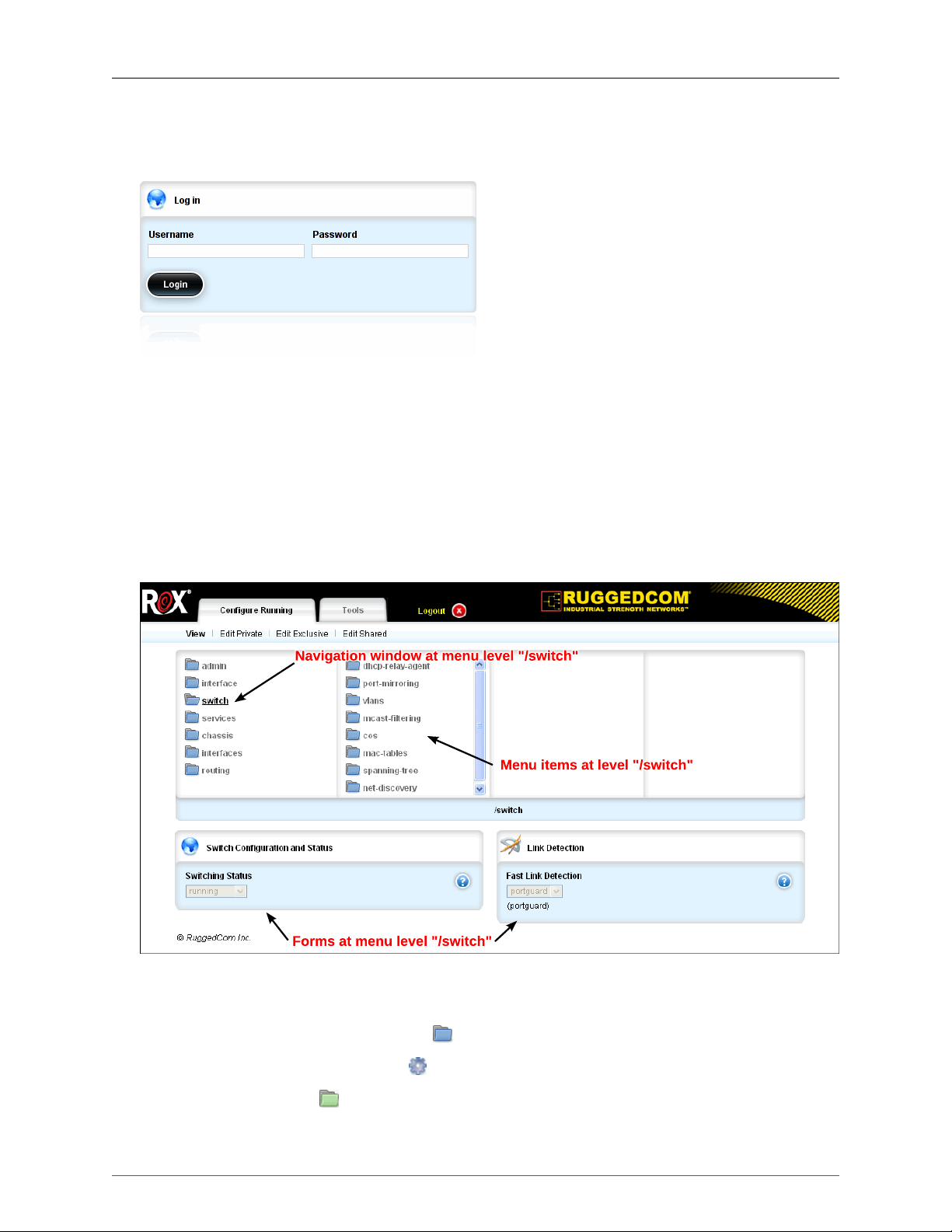
1. The ROX™ Web Interface
Start a web browser session and open a connection to the switch by entering a URL that specifies its
IP address (https://192.168.1.2, to continue with the example above). Once the web browser makes
contact with the switch, The resulting page should be the login prompt displayed below:
Figure 1.1. The ROX™ Login Form
Enter the default user name, "admin" and the configured password for the admin user. Click on the
Login button. The switch is shipped with a default administrator password, "admin". If authentication
is successful, the main menu is presented.
1.2. The Structure Of The Web Interface
The system configuration interface (the Configure Running tab) is organized as a hierarchical set of
linked menu entries, which may be traversed using the four-panel navigation window, as illustrated
below.
Figure 1.2. The ROX™ Web Interface
Menu items listed in a panel of the navigation window at a given point in the menu hierarchy may be:
•
Submenus, which are marked using the icon, or
•
Actions, which are marked using the icon.
Note that green submenu icons represent operational data.
ROX™ v2.2 User Guide 28 RuggedBackbone™ RX1500
Page 29

1. The ROX™ Web Interface
Tables and forms relevant to the selected menu item appear below the navigation window.
The icons in the upper left corner of the forms and tables are used to signify the type of content
represented in each form or table.
•
The green arrow icon signifies operational data.
•
The key icon signifies the key in key settings.
•
The blue globe icon signifies the global group (a high-level grouping of items).
•
The pencils and protractor icon signifies configuration data.
•
The paper and pencil icon signifies results. This icon is usually found on a form where there are
parameters to enter.
Every web page in the ROX™ user interface has a header, illustrated above, containing:
•
The ROX™ and RuggedCom logos and a Logout button, which terminates the current web
session.
• The tabs: Configure Running and Tools.
The Configure Running tab selects the configuration interface described above. A menu bar below the
page header displays the following editing mode controls:
• View: View configuration settings only.
• Edit Private: Enter a configuration editing mode where you can make changes to the system. Your
changes are applied to the active system only when you commit them. Edit sessions are self
contained: the changes made in your edit session are not visible to other users in other edit sessions.
• Edit Exclusive: Enter a configuration editing mode where, after committing your changes, you can
specify a timeout period to test the changes. At the end of the timeout period, your changes to revert
back to the original settings. Use this mode when you want to test changes before committing them
permanently. When you click Commit, a dialog prompts you to set a commit timeout. Type a value
and select a unit of time. ROX temporarily applies your changes to the active system for the specified
time. To cancel the commit and discard the changes, click Abort Commit before the time elapses.
To permanently commit your changes, click Commit before the time elapses.
In many cases, the tables appear on a screen closer to the top level and clicking on one of the submenus
brings up the form(s) associated with the table. For example, clicking on the Chassis menu and then
the Hardware submenu will display the Slot Hardware table. Further clicking on the pm1 submenu will
display the Slot Hardware form.
The Tools tab displays a menu of tools in the menu bar, with the following structure:
• Device Info: displays text from various system logs. You can specify the number of lines to view and
a text filter.
• Messages Viewer: displays all events from /var/log/messages.
• Syslog Viewer: displays syslog events from /var/log/syslog.
• Authlog Viewer: displays authentication events from /var/log/auth.log.
• Layer2log Viewer: displays Layer 2 events from /var/log/layer2.
• Kernlog Viewer: displays kernel events from /var/log/messages.
• Accessories
• Ping: an ICMP echo tool for IPv4 addresses
• Ping6: an ICMP echo tool for IPv6 addresses
ROX™ v2.2 User Guide 29 RuggedBackbone™ RX1500
Page 30
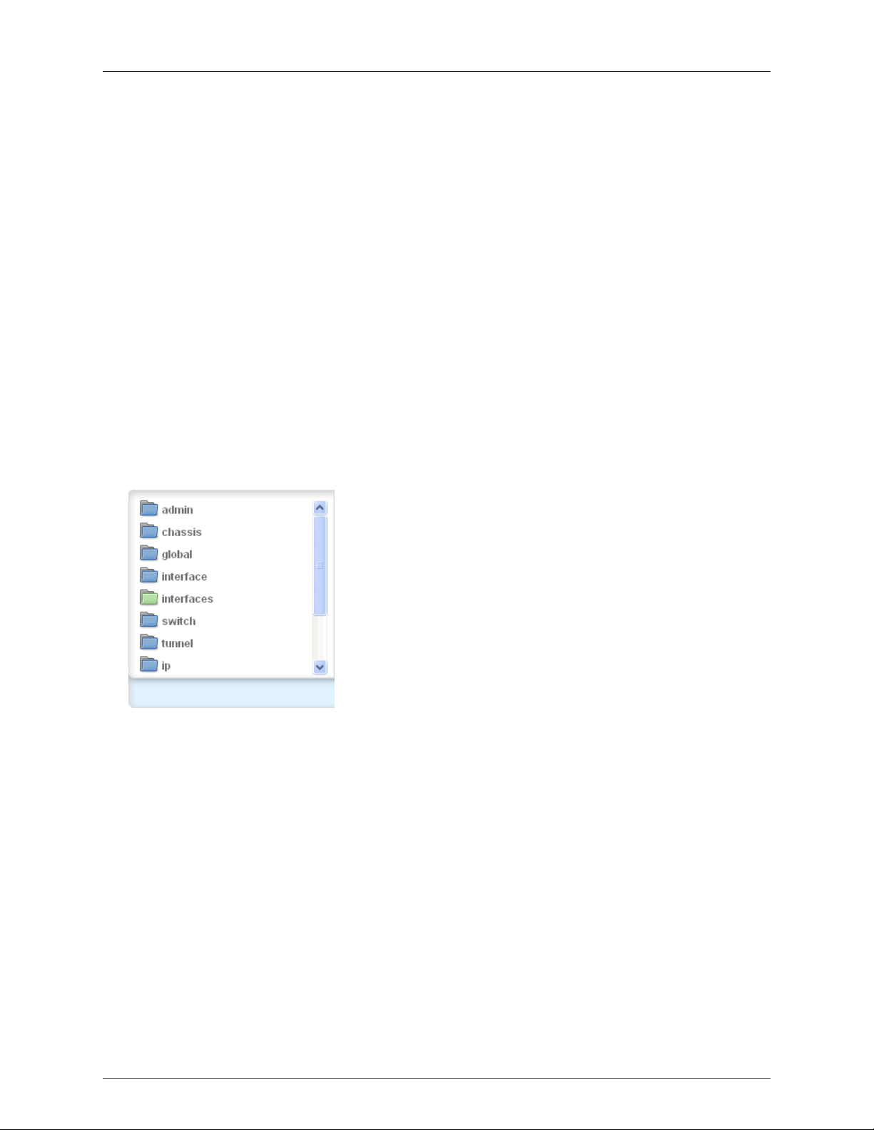
1. The ROX™ Web Interface
• Tcpdump: a packet analyzer for TCP/IP and other packets
• Traceroute: a tool for displaying route or path information and packet transit delays between IPv4
addresses
• Traceroute6: a tool for displaying route or path information and packet transit delays between IPv6
addresses
• CLI: a command line interface window
• Users: displays a list of currently connected users, provides controls to kick users off of the system,
and provides a message board to send messages to users.
• Upload: uploads configuration files, feature keys, elan certificates, ipsec certificates, ca certificates,
and crl certificates to the system from your workstation. From the Choose file type list, select the type
of file to upload. Click Choose File and navigate to and select a file on your workstation. To upload
the selected file, click Send.
• Download: downloads configuration files, feature keys, elan certificates, ipsec certificates, ca
certificates, crl certificates, log files, and rollback files from the system to your workstation. From the
Choose file type list, select the type of file to download. Click List files; a list of available files appears.
To download a file, right-click on a file name and select Save Link As (the name of the menu option
will vary, depending on your browser). To open a file in a new window or tab, click on a file name.
1.2.1. Top-level Menu Categories
Figure 1.3. Top-level Menu
Below is a description of the categories in the top-level menu that is shown above.
admin
The admin menu is used for configuring functions related to the administration of the router.
Functions include DNS, alarms, logging, authentication, users, software upgrade, notifications and
SNMP.
chassis
The chassis menu is used for configuring the chassis.
global
The global menu is used for configuring global functions including profiles for PPP and cellular
modems.
interface
The interface menu is used for configuring the interface, including (where applicable) sections for
WAN, serial, modem and trunks.
ROX™ v2.2 User Guide 30 RuggedBackbone™ RX1500
Page 31

1. The ROX™ Web Interface
interfaces
The interfaces menu displays the status of functions configured via the interface menu. For example,
eth functions can be configured using the eth submenu that is accessible from the interface menu.
The eth status can be viewed by clicking on the eth submenu of the interfaces menu.
switch
The switch menu is used for configuring Layer 2 packet switching functions. Functions included are
port security, DHCP relay agent, port mirroring, multicast filtering, CoS, mac tables, spanning tree,
VLANs, layer 3 switching and net discovery. You can also reset switched ports and clear switched
port statistics and cable diagnostic test results.
tunnel
The tunnel menu is used for configuring IP tunnels using IPsec, Layer 2 tunnelling functions and
Generic Routing Encapsulation (GRE).
ip
The ip menu is used for configuring the ROX™ system’s IP network interfaces.
qos
The qos menu is used for configuring traffic control.
routing
The routing menu is used for configuring the routing features. Included are sections on dynamic,
static, status and multicast routing.
security
The security menu is used for configuring security, including the firewall.
services
The services menu is used for configuring various services. These services include timekeeping,
VRRP, DHCP server and linkfailover.
1.3. Making Configuration Changes
In order to make configuration changes, select the desired Edit Private mode from the configuration
view. The same navigation window, tables and forms are redisplayed, but with additional controls, as
illustrated below.
ROX™ v2.2 User Guide 31 RuggedBackbone™ RX1500
Page 32

1. The ROX™ Web Interface
Figure 1.4. Example of Edit Private Mode
The example above depicts the process of adding a VLAN ID to an interface. The interface/eth/cm1
menu can be seen to contain:
• A configuration entry, followed by a "delete" icon, , which removes the corresponding entry.
Clicking on <add vlan> displays the Add ID form below the navigation window, which prompts for a VLAN
ID. Entering a VLAN ID and clicking Add adds the selected VLAN to the currently selected interface.
Note the help button, , on the Add ID form which, when clicked, displays context-sensitive information
about the corresponding data field.
A red asterisk appears beside fields that are mandatory for configuration, when in Edit Private mode.
Note the red asterisk next to the field name (VLAN ID) in the Key settings form.
Several controls below the header and menu bar are used to affect the behaviour of the changes made
during the current configuration editing session:
Changes
Present a summary of all pending changes.
Validate
Automatically check the validity of pending changes.
Revert All
Abort all pending changes.
Commit
Commit all pending changes - save changes persistent configuration storage and to the running
system.
Rollback
Present a list of change sets made to date, with an option to revert a selected set of changes.
ROX™ v2.2 User Guide 32 RuggedBackbone™ RX1500
Page 33

1. The ROX™ Web Interface
Exit Transaction
Exit from configuration editing mode. If there are pending changes, a prompt will be presented to
verify the discarding of all pending changes.
1.3.1. Configuring Tables Using Key Settings Forms
Much of the information in ROX™ is organized into tables. Each table is indexed or sorted by a key,
which is a piece of information such as a name, address, or other variable. For example, a Chassis
Hardware table is indexed by slot name (with the slot name being the key) and a DNS Server table is
indexed by IP address (with the IP address being the key). Key information can be added using the key
settings forms. To add server information to a DNS server table, for example, add the server address
to the key settings form and this information will appear in the DNS server table.
Figure 1.5. Adding Key Information
To add key information to a table, go into the Edit Private mode and enter the information into the
key settings form. Click the Commit button. When you have finished making all changes, click the Exit
Transaction button to return to the View mode.
ROX™ v2.2 User Guide 33 RuggedBackbone™ RX1500
Page 34

1. The ROX™ Web Interface
Figure 1.6. Key Information in a Table
The information entered in the key settings form will now appear in the table. Note that the table appears
on the server screen, while the key settings form appears on the address screen, which is a submenu
linked to the server screen (see below).
Figure 1.7. Example of Key Settings 1
ROX™ v2.2 User Guide 34 RuggedBackbone™ RX1500
Page 35

1. The ROX™ Web Interface
Figure 1.8. Example of Key Settings 2
The submenus that display the key settings forms appear in the far right column of the screen.
Sometimes, it will be necessary to traverse several menu screens to get to a key settings form.
1.3.2. Viewing More Information in Tables
Occasionally, a table may have more entries that are not visible in the initial view. If you encounter a
table that has a line of linked text at the top with the word "Next", and a number in parentheses ( ), you
can click on the "Next" link and access additional entries. The two figures below illustrate this situation.
In this case, there are 18 entries in the table. The first table contains 16 entries and 2 entries follow
in the next table.
ROX™ v2.2 User Guide 35 RuggedBackbone™ RX1500
Page 36

1. The ROX™ Web Interface
Figure 1.9. First Table of Information
Figure 1.10. Second Table of Information
The second table of information shows the balance of the entries and contains a link back to the previous
entries.
ROX™ v2.2 User Guide 36 RuggedBackbone™ RX1500
Page 37

2. System Administration
2. System Administration
This chapter describes administration-related functions and the Administration menu. Information on
the Administration submenus is found throughout Part 1 of this guide.
2.1. Administration menu
Figure 2.1. Administration menu
The Administration (Admin) menu is accessible from the main menu. Use this menu to link to submenus
related to alarms, DNS, logging, SNMP, authentication, user IDs and passwords, software versions
(upgraded) and netconf.
As well, you can link directly from the Admin menu to commands called "actions" (see below) that
will clear or acknowledge all alarms, shut down or reboot the system, set the system clock or restore
factory defaults.
2.2. System Commands
This section describes where to find basic system commands using the Administration menu and its
menu actions. The following forms are accessible from the Administration menu.
Figure 2.2. Clear All Alarms Menu Action form
To clear all alarms, click on the clear-all-alarms menu action and then click the Perform button on the
Clear All Alarms form.
Figure 2.3. Acknowledge All Alarms Menu Action form
ROX™ v2.2 User Guide 37 RuggedBackbone™ RX1500
Page 38

2. System Administration
To acknowledge all alarms, click on the acknowledge-all-alarms menu action and then click the Perform
button on the Acknowledge All Alarms form.
Figure 2.4. Shutdown the Device Menu Action form
To shut down the device, click on the shutdown menu action and then click the Perform button on the
Shutdown the Device form.
Figure 2.5. Reboot the Device Menu Action form
To reboot the device, click on the reboot menu action and then click the Perform button on the Reboot
the Device form.
Figure 2.6. Set New Time and Date form
The Set New Time and Date form configures the current time and date settings.
Figure 2.7. Set Clock on Target Device form
To set the clock on the target device, click on the setSystemClock menu action, then enter the relevant
time/date information into the Set New Time and Date form. The information must be in the following
format: YYYY-MM-DD HH:MM:SS. After entering this information, click the Perform button on the Set
clock on target device form.
For more detailed information on time synchronization, refer to Chapter 3, Time Synchronization.
ROX™ v2.2 User Guide 38 RuggedBackbone™ RX1500
Page 39

2. System Administration
Figure 2.8. Restore-factory-defaults Trigger Action form
To restore factory defaults to the system, click on the restore-factory-defaults menu action and then
click the Perform button on the Restore-factory-defaults Trigger Action form.
The Administration, Hostname, Timezone and Current System Time forms are accessible from the
Admin menu.
Figure 2.9. Administration form
System Name
Synopsis: A string
Default: System Name
An administratively-assigned name for this managed node. By convention, this is the node's fullyqualified domain name. If the name is unknown, the value is the zero-length string.
Location
Synopsis: A string
Default: Location
The physical location of this node (e.g., 'telephone closet, 3rd floor'). If the location is unknown, the
value is the zero-length string.
contact
Synopsis: A string
Default: Contact
The textual identification of the contact person for this managed node, together with information on
how to contact this person. If no contact information is known, the value is the zero-length string.
Figure 2.10. Hostname form
ROX™ v2.2 User Guide 39 RuggedBackbone™ RX1500
Page 40

2. System Administration
The hostname is the name of the product. (This can be changed, though.)
name
Synopsis: A string conforming to: "[A-Za-z0-9]([A-Za-z0-9-]*[A-Za-z0-9])*"
Default: ruggedcom
The hostname is the name of this device.
domain
Synopsis: Domain name (RFC 1034)
Default: localdomain
The domain for this hostname.
Figure 2.11. Timezone form
Timezone Category
Synopsis: string
Selects the timezone. Note that the Etc/GMT timezones conform to the POSIX style and have their
signs reversed from common usage. In POSIX style, zones west of GMT have a positive sign; zones
east of GMT have a negative sign.
Timezone
Synopsis: string
Selects the timezone.
Figure 2.12. Setting the Timezone Form - in Edit Private Mode
To set the time zone, enter Edit Private mode and click on the Timezone Category field. Use the
drop-down menu which appears to select the appropriate time zone. Daylight saving time will adjust
automatically, if applicable to your zone.
Figure 2.13. Current System Time form
The Current System Time form displays the current time.
UTC Time
Synopsis: string
The current GM Time
Local Time
Synopsis: string
ROX™ v2.2 User Guide 40 RuggedBackbone™ RX1500
Page 41

2. System Administration
The current local time
2.3. Administrative Access Control
The following access control forms are accessible from the Administration menu - by clicking on the
main menu under admin.
Figure 2.14. CLI Sessions form
enabled
Synopsis: boolean
Default: true
Provides the ability to configure CLI features on the device.
Listen IP
Synopsis: IPv4 address in dotted-decimal notation
Synopsis: IPv6 address in colon-separated hexadecimal notation
Default: 0.0.0.0
The IP Address the CLI will listen on for CLI requests (default 0.0.0.0).
Listen Port
Synopsis: unsigned short integer
Default: 22
The port on which the CLI listens for CLI requests. The default is port 22.
Extra IP:Ports
Synopsis: A string
Synopsis: "extra-ip-ports" occurs in an array.
The CLI will also listen on these IP Addresses:Port values. Add ':#' to set non-default port value #.
(ie. xxx.xxx.xxx.xxx:19343 [::] [::]:16000)
ROX™ v2.2 User Guide 41 RuggedBackbone™ RX1500
Page 42

2. System Administration
Maximum Number of CLI Sessions
Synopsis: unsigned integer
Synopsis: - the keyword { unbounded }
Default: 10
The maximum number of concurrent CLI sessions
Idle Timeout
Default: PT30M
Maximum idle time before terminating a NETCONF session. If the session is waiting for notifications,
or has a pending confirmed commit, the idle timeout is not used. The default value is 0, which
means no timeout.
greeting
Synopsis: string
Default: Welcome to Rugged CLI
Sets the greeting presented when the user logs in to the CLI.
Figure 2.15. Idle-timeout field
Clicking on the Idle-timeout field on the CLI Sessions form allows you to choose a value for this field.
The default value is PT30M, which stands for "Precision Time 30 Minutes". This refers to the time when
an inactive session expires or times out. Only integer values corresponding to the following fields can
be entered: Year, Month, Day, Hour, Min, Sec, or Ms. The example above shows the default value of
PT30M, which corresponds to the Min field.
Figure 2.16. Session Limits form
The Session Limits form is used for setting the maximum number of users sessions on a northbound
channel.
Maximum Sessions Total
Synopsis: unsigned integer
Synopsis: - the keyword { unbounded }
Default: 70
Puts a limit to the total number of concurrent sessions to ROX 2.
ROX™ v2.2 User Guide 42 RuggedBackbone™ RX1500
Page 43

2. System Administration
Figure 2.17. STFP Sessions form
The SFTP Sessions form sets the parameters for Secure File Transfer Protocol (SFTP) sessions.
enabled
Synopsis: boolean
Default: false
Enable/Disable the SFTP user interface
Listen IP
Synopsis: IPv4 address in dotted-decimal notation
Synopsis: IPv6 address in colon-separated hexadecimal notation
Default: 0.0.0.0
The IP Address the SFTP will listen on for SFTP requests (default 0.0.0.0).
Listen Port
Synopsis: unsigned short integer
Default: 2222
The port the SFTP will listen on for SFTP requests (default 2222).
Extra IP:Ports
Synopsis: A string
Synopsis: "extra-ip-ports" occurs in an array.
The SFTP will also listen on these IP Addresses:Port values. Add ':#' to set non-default port value
#. (ie. xxx.xxx.xxx.xxx:19343 [::] [::]:16000)
Maximum Number of SFTP Sessions
Synopsis: unsigned integer
Synopsis: - the keyword { unbounded }
Default: 10
The maximum number of concurrent SFTP sessions
ROX™ v2.2 User Guide 43 RuggedBackbone™ RX1500
Page 44

2. System Administration
Figure 2.18. WWW Interface Sessions
The WWW Interface Sessions form provides control of WWW User Interface settings.
enabled
Synopsis: boolean
Default: true
Provides the ability to configure WebUI features on the device.
Listen IP
Synopsis: IPv4 address in dotted-decimal notation
Synopsis: IPv6 address in colon-separated hexadecimal notation
Default: 0.0.0.0
The IP Address the CLI will listen on for WebUI requests (default 0.0.0.0).
Listen Port
Synopsis: unsigned short integer
Default: 443
The port on which the WebUI listens for WebUI requests. The default is port 443.
Extra IP:Ports
Synopsis: A string
Synopsis: "extra-ip-ports" occurs in an array.
The WebUI will also listen on these IP Addresses:Port values. Add ':#' to set non-default port value
#. (ie. xxx.xxx.xxx.xxx:19343 [::] [::]:16000)
Maximum Number of WebUI Sessions
Synopsis: unsigned integer
Synopsis: - the keyword { unbounded }
Default: 20
The maximum number of concurrent WebUI sessions
ROX™ v2.2 User Guide 44 RuggedBackbone™ RX1500
Page 45

2. System Administration
Idle Timeout
Default: PT30M
Maximum idle time before terminating a WebUI session. If the session is waiting for notifications, or
has a pending confirmed commit, the idle timeout is not used. The default value is 0, which means
no timeout.
Figure 2.19. Idle-timeout field
Clicking on the Idle-timeout field on the WWW Interface Sessions form allows you to choose a value for
this field. The default value is PT30M, which stands for "Precision Time 30 Minutes". This refers to the
time when an inactive session expires or times out. Only integer values corresponding to the following
fields can be entered: Year, Month, Day, Hour, Min, Sec, or Ms. The example above shows the default
value of PT30M, which corresponds to the Min field.
2.4. User Accounts
Figure 2.20. Users menu
The Users menu is accessible from the main menu under admin. This menu is used to access
commands needed for creating and managing passwords for administrators, operators and guests.
Both private and public passwords can be created. The Admin Users ID Table (below) can be found
on the same screen as the Users menu. Clicking on admin, guest, oper, private or public will lead you
to the Users ID forms for each of these options.
Figure 2.21. Users table
ROX™ v2.2 User Guide 45 RuggedBackbone™ RX1500
Page 46

2. System Administration
Figure 2.22. Users form
name
Synopsis: string
User Name
password
Synopsis: A string
User Password
role
Synopsis: string - one of the following keywords { guest, operator, administrator }
Default: guest
User Role
Figure 2.23. Users Screen in Edit Private View
Passwords can be managed, added and deleted while in the Edit Private view.
ROX™ v2.2 User Guide 46 RuggedBackbone™ RX1500
Page 47

2. System Administration
2.5. Software Upgrade
ROX™ supports two system partitions. One is always active and the other is inactive. ROX™ always
applies software upgrades to the inactive partition, providing the following advantages:
1. The current system is unaffected and can operate normally while the upgrade is in progress
2. The current partition remains intact, allowing you to roll back to the original system if needed
After a successful upgrade, the next reboot boots the upgraded partition.
The following applies to software upgrades:
• All system configurations and all user files (featurekeys, configuration files etc.) are carried over to
the upgraded partition.
• All configurations are locked during an upgrade and until the upgraded partition is booted. This
prevents post-upgrade configuration changes that are not carried over to the upgraded partition.
• Completed upgrades can be declined before the next reboot.
• If major system failures are detected upon booting the upgraded partition, the system will
automatically roll back to the previous partition.
Figure 2.24. Software-Upgrade menu
The Software-Upgrade menu is accessible from the main menu under admin. The path to this menu
is admin/software-upgrade. This menu links to functions that will enable the user to upgrade software,
launch the upgraded software, decline new upgrades, and rollback and reboot. The Upgrade Monitoring
form and Upgrade Settings form appear on the same screen as the Software-Upgrade menu.
Figure 2.25. Upgrade Settings
In edit mode, define an upgrade server on the Upgrade Settings form by setting the Server URL and
Target ROX Version parameters. The Upgrade Server URL is the location of the ROX™ software
repository. Target ROX Version is the version of ROX to which you are upgrading. For information on
setting up an upgrade server, see Appendix C, Setting Up An Upgrade Server.
Upgrade Server URL
Synopsis: string
repository-url
Target ROX Version
Synopsis: string
ROX™ v2.2 User Guide 47 RuggedBackbone™ RX1500
Page 48

2. System Administration
target-version
Figure 2.26. Upgrade Monitoring
The Upgrade Monitoring form displays the status of the current upgrade operation.
software-partition
Synopsis: A string
The current active partition number. The unit has two software partitions: #1 and #2. Upgrades are
always peformed to the other partition.
Current Version
Synopsis: A string
The current operating software version.
Upgrade Phase
Synopsis: string - one of the following keywords { Failed, Completed successfully, Unknown
state, Installing packages, Downloading packages, Copying filesystem, Estimating upgrade size,
Inactive }
The current phase or state of the upgrade. It is one of 'Estimating upgrade size', 'Copying filesystem',
'Downloading packages', 'Installing packages', Unknown state', 'Completed successfully', or
'Failed'. These phrases will not vary, any may be used programmitcally for ascertaining state.
status-message
Synopsis: string
Additional details on the status of the upgrade
Phase 1: Filesystem Sync (% complete)
Synopsis: integer
Phase 1 of the upgrade involves synchronizing the filesystem with the partition to which we are
upgrading.
This reflects the estimated percent complete.
Phase 2: Package Download (% complete)
Synopsis: integer
Phase 2 of the upgrade downloads all packages that require an update. This reflects the estimated
percent complete.
ROX™ v2.2 User Guide 48 RuggedBackbone™ RX1500
Page 49

2. System Administration
Phase 3: Package Installation (% complete)
Synopsis: integer
Phase 3 of the upgrade installs all packages that require an update. This reflects the estimated
percent complete.
Last Attempt
Synopsis: A string
The date and time of completion of the last upgrade attempt.
Last Result
Synopsis: string - one of the following keywords { Interrupted, Declined, Not Applicable, Reboot
Pending, Unknown, Upgrade Failed, Upgrade Successful }
Indicates whether or not the last upgrade completed successfully
Figure 2.27. Launch Upgrade
To launch an upgrade, click on the launch-upgrade menu action and then click the Perform button on
the Launch Upgrade form. Note that the server URL and version name information must be entered
in the Upgrade Settings form prior to launching the upgrade. For detailed step-by-step instructions on
how to perform a software upgrade, refer to Appendix A, Upgrading Software.
Figure 2.28. Decline Upgrade
To decline an upgrade, click on the decline-upgrade menu action and then click the Perform button on
the Decline Upgrade form.
Figure 2.29. Rollback and Reboot
To roll back an upgrade, click on the rollback-reboot menu action and then click the Perform button on
the Rollback and Reboot form.
Rollback and Reboot “rolls back” the system to the previously active software installation, which is
stored on the alternate of two filesystem partitions in flash memory. Performing this action will result in
rebooting the system using the old software installation along with its configuration.
ROX™ v2.2 User Guide 49 RuggedBackbone™ RX1500
Page 50

2. System Administration
Any configuration changes made since the last software upgrade will not be reflected after
rebooting to the "rolled-back" software installation.
2.6. ROXflash Cross-Partition Imaging Tool - Software Downgrade
ROX™ supports two system partitions. One is always active and the other is inactive. ROXflash allows
you to flash any ROX™ software version to the inactive partition.
To obtain a flash image, contact your RuggedCom sales representative. Place the flash image in a
location on your network accessible to the ROX™. On the ROXflash form, enter the URL for the flash
image and flash it to the inactive partition. The flash image will be active after the next reboot.
2.6.1. Uses
Use ROXflash for downgrading to an earlier version of the ROX software. For example, your
organization has certified a specific version of the ROX software, and all ROX™ units must run the
certified version. Due to an equipment issue, you need to install a new ROX™ unit that comes with a
later version of the software. In this example, use ROXflash to install the earlier version of the software
on the new unit.
Use ROXflash only to install earlier versions of the ROX software. Software upgrades to later versions
should be performed using the Software Upgrade function.
Table 2.1, “Differences Between ROXflash and Software Upgrade Functions” outlines some of the
key differences between the ROXflash and Software Upgrade functions. For more information on the
Software Upgrade function, see Section 2.5, “Software Upgrade”.
ROXflash Software Upgrade
Used primarily for downgrades.
Uses a flash image ordered from a
RuggedCom Sales Representative.
Downgrades to any software version supplied in an image.
Does not transfer system configurations and
files to the next software version. ROXflash
returns the unit to its factory default settings.
Configurations must be reloaded after rebooting.
Table 2.1. Differences Between ROXflash and Software Upgrade Functions
Used only for upgrades; does not support
downgrades (except for rollbacks).
Uses an archive of ROX™ software packages
hosted on an upgrade server. The archive is
available on RuggedCom.com for download.
Rolls back only to the last version
stored on the alternate partition.
Transfers configurations and files to the
upgraded software version; reverts to the
previous configurations in a rolled back version.
2.6.2. ROXflash Configuration
Figure 2.30. ROX-Imaging menu
ROX™ v2.2 User Guide 50 RuggedBackbone™ RX1500
Page 51

2. System Administration
The ROX-Imaging menu is accessible from the main menu under admin. The ROXflash Monitoring form
appears on the same screen as this menu.
Figure 2.31. ROXflash Monitoring form
This form shows the progress and state of the roxflash operation (during an upgrade or downgrade).
ROXflash Phase
Synopsis: string - one of the following keywords { Failed, Completed successfully, Unknown
state, Imaging partition, Downloading image, Inactive }
The current phase or state of the ROXflash operation. It is always one of: 'Inactive', 'Downloading
image', 'Imaging partition', 'Unknown state', Completed successfully, or 'Failed'. These phrases do
not vary, and may be used programatically for ascertaining state.
ROXflash Status
Synopsis: A string
Detailed messages about ROXflash progress.
Phase 1: Image Download (% complete)
Synopsis: integer
Phase 1 of ROXflash downloads the image from a URL. This reflects percent complete.
Phase 2: Image Flashing (% complete)
Synopsis: integer
Phase 2 of ROXflash flashes the image to the alternate partition. This reflects percent complete.
Figure 2.32. ROXFlash menu
ROX™ v2.2 User Guide 51 RuggedBackbone™ RX1500
Page 52

2. System Administration
Figure 2.33. ROXFlash forms
To perform a ROXFlash operation, enter the URL into the ROXflash form and then click the Perform
button. Next, monitor the progress by returning to the ROXflash Monitoring form.
2.7. Scheduling Jobs
Use job scheduling to execute CLI (command line interface) commands at a specified time and date or
in response to configuration changes. The path to the scheduler menu is admin/scheduler.
Figure 2.34. Scheduler menu
There are two types of scheduled jobs:
• periodic jobs launch at a defined interval. Set the interval in the Minute, Hour, Day of Month, and
Month parameters. Use the Day of Week parameter to launch the job on a specific day of the week,
such as every Friday. For information on how periodic scheduled jobs behave when you omit date
and time parameters, see Figure 2.36, “Scheduled Jobs Form” and the field descriptions.
• configchange jobs launch only when the configuration changes.
The job scheduler Command parameter accepts most ROX CLI commands. Do not use commands
that require a manual response or confirmation.
The /admin/scheduler/scheduled-jobs table lists the scheduled jobs and their settings:
ROX™ v2.2 User Guide 52 RuggedBackbone™ RX1500
Page 53

2. System Administration
Figure 2.35. Scheduled-jobs table
To add a scheduled job:
• Enter edit mode, navigate to admin/scheduler, and click <Add scheduled-jobs>.
• On the Key settings form, enter a name for the job and click Add.
• On the Scheduled Jobs form, set the job parameters.
Figure 2.36. Scheduled Jobs form
Job Type
Synopsis: string - one of the following keywords { periodic, configchange }
Default: periodic
Determines when to launch the scheduled job:
• periodic: the job launches at a set date and time.
• configchange: the job launches when the configuration changes.
Minute
Synopsis: A string
Default:
For periodic jobs, sets the minutes portion of the job launch time. Valid values are in the range of
0 to 59. If no value is set, the scheduler uses the default value of 0 and launches the job every
hour on the the hour.
• To specify a single value, enter the value in the field. For example, to launch the job 10 minutes
past the hour, enter 10
• To specify a list of values, enter the values as a comma-separated list. For example, to launch
the job at 14, 30, and 45 minutes past the hour, enter 15,30,45
ROX™ v2.2 User Guide 53 RuggedBackbone™ RX1500
Page 54

2. System Administration
• To specify a range of values, enter the range as comma-separated values. For example, to launch
the job every minute between 30 and 45 minutes past the hour, enter 30-45
Hour
Synopsis: A string
For periodic jobs, sets the hour portion of the job launch time, in the 24-hour clock format. Valid
values are in the range of 0 to 23. If no value is set, the job launches every hour at the time set
in the Minute field.
• To specify a single value, enter the value in the field. For example, to launch the job at 5:00 pm,
enter 17
• To specify a list of values, enter the values as a comma-separated list. For example, to launch
the job at 9:00 am, 12:00 pm, and 5:00 pm, enter 9,12,17
• To specify a range of values, enter the range as comma-separated values. For example, to launch
the job every hour between 9:00 am and 5:00 pm, enter 9-17
Day of Month
Synopsis: A string
For periodic jobs, sets the day of the month on which to run the scheduled job. Valid values are in
the range of 1 to 31. If no value is set, the job launches every day.
• To specify a single value, enter the value in the field. For example, to launch the job on the tenth
day of the month, enter 10
• To specify a list of values, enter the values as a comma-separated list. For example, to launch
the job on the first, fifteenth, and thirtieth days of the month, enter 10,15,30
• To specify a range of values, enter the range as comma-separated values. For example, to launch
the job on days one through fifteen, enter 1-15
Month
Synopsis: A string
For periodic jobs, sets the month in which to run the scheduled job. Valid values are in the rage of
1 to 12. If no value is set, the job launches every day.
• To specify a single value, enter the value in the field. For example, to set the month to February,
enter 2
• To specify a list of values, enter the values as a comma-separated list. For example, to set the
months to January, June, and December, enter 1,6,12
• To specify a range of values, enter the range as comma-separated values. For example, to set
the months to January through June, enter 1-6
Day of Week
Synopsis: A string
For periodic jobs, sets the day of the week on which to run the scheduled job. Valid entries are in
the range of 0 to 6, where 0 represents Sunday, 1 represents Monday, and so on. If no value is
set, the job launches every day.
• To specify a single value, enter the value in the field. For example, to set the day to Monday,
enter 1
• To specify a list of values, enter the values as a comma-separated list. For example, to set the
days to Friday, Saturday, and Sunday, enter 5,6,0
• To specify a range of values, enter the range as comma-separated values. For example, to set
the days to Monday through Friday, enter enter 1-5
Command
Synopsis: A string
ROX™ v2.2 User Guide 54 RuggedBackbone™ RX1500
Page 55

2. System Administration
The CLI commands to execute at the scheduled time. The command or list of commands can be
up to 1024 characters in length. For example, this command saves the running configuration to a
file named 'myconfig': show running-config | save myconfig
Do not use interactive commands or commands that require a manual response or confirmation.
2.8. The Featurekey
2.8.1. Overview
Some ROX™ software features are only available by purchasing an appropriate feature level. Consult
the product datasheet for available feature levels and the specific capabilities they enable.
When specifying a feature level at the time of ordering, the featurekey is entered into the electronic
signature on the device . The featurekey is independent of the compact flash card and is retained by
the device should the card be replaced.
2.8.2. Upgrading Feature Levels in the field
Feature levels can be purchased and upgraded in the field with a file-based featurekey. To update your
featurekey, contact your RuggedCom sales representative. For RX15xx products, you need to provide
the serial number for the unit you are upgrading. The upgraded featurekey is licensed for the serial
number you provide. For instructions on how to view your serial numbers, see Section 2.8.4, “Viewing
RuggedCom Serial Numbers”.
To install the featurekey file, use the Install Files form found under that admin menu. You can also use
the file scp-featurekey-from-url command from the ROX™ Command Line Interface. For instructions
on how to upload the featurekey file, see Section 2.8.5, “Uploading a Featurekey”.
The upgraded featurekey resides on the device’s compact flash card. ROX™ evaluates both the device
featurekey and the file-based featurekey, and then enables the most capable feature level described
by the keys.
When using file-based featurekeys, the feature level follows the compact flash card. Moving the compact
flash card to another device moves the feature level to the new device. If you want the upgraded feature
level to be tied to a specific device, contact your RuggedCom sales representative to arrange for an
RMA (Return to Manufacturer Authorization) to have the featurekey programmed into the device.
2.8.3. When a File-based featurekey does not Match the Hardware
In rare circumstances, you may need to remove the compact flash card from one device and transfer
it to another device. For example: you may have a backup device to replace a malfunctioning unit, and
you choose to use the upgrade featurekey on the malfunctioning unit’s compact flash card to retain your
configuration in the backup unit.
The file-based featurekey on the compact flash card is licensed for a particular unit, but can be
transferred to another unit to ensure continuity of service. When you transfer the file-based featurekey
from its licensed unit to another unit for which it is not licensed, the device behaves in the following
manner:
1. The device enables the higher feature level found on the compact flash card.
2. The device raises a non-clearable alarm, indicating a hardware mismatch with the featurekey.
3. The alarm trips the fail-safe relay and turns on the main alarm LED.
To acknowledge the alarm and resolve the issue, follow these steps:
1. Acknowledge the alarm. (For instructions on acknowledging alarms , see Chapter 6, Alarms.)
2. Contact a Ruggedcom sales representative and order a featurekey matching the serial numbers
of the hardware you are using.
ROX™ v2.2 User Guide 55 RuggedBackbone™ RX1500
Page 56

2. System Administration
2.8.4. Viewing RuggedCom Serial Numbers
When you order a new featurekey, you need to provide RuggedCom with the chassis serial number.
This section describes how to view your device’s serial numbers through the CLI screen in the ROX™
web interface.
Follow these steps to display the serial numbers for your device:
Procedure 2.1. Viewing RuggedCom Serial Numbers
1. Launch a web browser and navigate to your device’s IP address. Log in to ROX™. The ROX web
interface appears.
2. Click the Tools tab and click the CLI link. The CLI screen appears.
Figure 2.37. CLI in the ROX™ Web Interface
3. At the Operational mode command line prompt, type show chassis and press Enter. Chassis
information appears:
ruggedcom# show chassis
chassis
chassis-status
model RX1501 software license "Layer 2 Standard Edition" order code ...
hardware
slot-hardware
ORDER
SLOT FIELD DETECTED MODULE SERIAL NUMBER
------------------------------------------------------------------------------------ pm1 XX none none
lm1 XX none none
lm2 TC4 T1/E1 w/ 4x RJ48 L15R-3333-PR301
lm3 D02 DDS w/ 1x RJ48 7
lm4 XX none none
lm5 CG01 1000TX w/ 2x RJ45 L15R-3109-PR001
lm6 XX none none
main CM04A RX1501 8 Gigabit Layer 2 w/ 6 LM slots and 1 PM slots R15R-1310-PR032
In the slot-hardware table, make note of the main slot serial number (highlighted in bold
text in the example above).
4. When ordering a new featurekey, provide the main slot serial number to RuggedCom.
ROX™ v2.2 User Guide 56 RuggedBackbone™ RX1500
Page 57

2. System Administration
2.8.5. Uploading a Featurekey
After receiving your featurekey file from RuggedCom, save the file to a computer that is accessible to
your device through your network.
2.8.5.1. Uploading a Featurekey Using the Web User Interface
Install Featurekey files using the Install Files forms found under the admin menu.
To install a featurekey file, navigate to admin/install-files. The Install Files form appears. In the in the File
type field, select featurekey. In the URL field, enter the URL to the file. On the Install Files to Devices
form, click the Perform button.
Figure 2.38. Install Files forms
For more information on installing files, see Section 2.9.1, “Installing Files”.
2.8.5.2. Uploading a Featurekey Using the Command Line Interface
To upload the file to your device, you will need to know the following information:
• the featurekey filename.
• a user name and password to log in to the computer where you saved the featurekey file.
• the hostname or IP address of the computer where you saved the featurekey file.
Follow these steps to upload a featurekey file to your device:
Procedure 2.2. Uploading a Featurekey File
1. Launch a web browser and navigate to your device’s IP address. Log in to ROX™. The ROX™
web interface appears.
2. Click the Tools tab and click the CLI link. The CLI screen appears.
3. In Operational mode, at the command line prompt, type the following command:
file scp-featurekey-from-url {username}@{host}:{path}{filename} {filename}
Where:
• {username} is the name of a user who can log in to the computer where you saved the featurekey
file.
• {host} is hostname or IP address of the computer where you saved the featurekey file.
• {path} is the directory path to the featurekey file on the computer.
ROX™ v2.2 User Guide 57 RuggedBackbone™ RX1500
Page 58

2. System Administration
• {filename} is the name of the featurekey file.
For example:
file scp-featurekey-from-url wsmith@10.200.20.39:/files/keys/1_cmRX1K-12-11-0015.key
1_cmRX1K-12-11-0015.key
4. Type the command with your parameters and press Enter. When prompted, type the user’s
password and press Enter. The system uploads the featurekey file:
ruggedcom# file scp-featurekey-from-url wsmith@10.200.20.39:/files/keys/
1_cmRX1K-12-11-0015.key 1_cmRX1K-12-11-0015.key
wsmith@10.200.20.39's password:
1_cmRX1K-12-11-0015.key 100% 192 0.2KB/s 00:00
ruggedcom#
5. To view the contents of the featurekey file, type the following command:
file show-featurekey {filename}
Where:
• {filename} is the name of the featurekey file.
For example:
file show-featurekey 1_cmRX1K-12-11-0015.key
6. Type the command with your featurekey filename and press Enter. The system displays the
contents of the featurekey file:
ruggedcom# file show-featurekey 1_cmRX1K-12-11-0015.key
GPG_FEATUREKEY_LEVEL=1
GPG_FEATUREKEY_CM_SERIALNUMBER=RX1K-12-11-0015
GPG_FEATUREKEY_SIGNATURE=iEYEABECAAYFAk091pAACgkQP2pya+G5kdZeKACeKdHUB2G1T73Dymq8IjSdYDKAiskAn
3abBpCEhfLXxY2ZlVbvGNwDZow2
ruggedcom#
7.
On the CLI screen, click Stop to close the CLI session.
2.8.6. Backing Up a Featurekey Using the Web User Interface
Featurekey files can be backed up using the following forms. These forms are accessible from the
admin menu.
To back up a featurekey file, navigate to admin/backup-files. The Backup Files form appears. In the
File type field, select featurekey. Enter additional parameters on the form. On the Backup Files From
Devices form, click the Perform button.
ROX™ v2.2 User Guide 58 RuggedBackbone™ RX1500
Page 59

2. System Administration
Figure 2.39. Backup Files forms
For more information on backing up files, see Section 2.9.2, “Backing Up Files”.
2.9. Installing and Backing Up Files
You can install and back up files using the following forms found under the admin menu.
Figure 2.40. Administration menu
2.9.1. Installing Files
To install a file, click install-files. The Install Files forms appear.
ROX™ v2.2 User Guide 59 RuggedBackbone™ RX1500
Page 60

2. System Administration
Figure 2.41. Install Files forms
On the Install Files form, select the file type and enter a URL. On the Install Files To Devices form,
click the Perform button.
2.9.2. Backing Up Files
To back up a file, click on backup-files. The Backup Files forms appear.
Figure 2.42. Backup Files forms
On the Backup Files form, select the file type and enter the required parameters. On the Backup Files
From Devices form, click the Perform button.
ROX™ v2.2 User Guide 60 RuggedBackbone™ RX1500
Page 61

2. System Administration
2.10. Deleting Log Files
Figure 2.43. Delete-logs menu
To delete log files, click the Perform button on the Delete Log Files form. This form is accessible at
admin/delete-logs.
Figure 2.44. Delete Log Files form
2.11. Saving Full Configurations
Save full configurations to a file using the forms below. These forms are accessible at admin/save-fullconfiguration.
Figure 2.45. Save-full-configuration menu
ROX™ v2.2 User Guide 61 RuggedBackbone™ RX1500
Page 62

2. System Administration
Figure 2.46. Save Full Configuration forms
To save full configurations to a file, select the format and enter the parameters in the Save Full
Configuration form, then click the Perform button in the Saving Full Configuration form.
2.12. Loading Full Configurations
Load full configurations to a file using the forms below. These forms are accessible at admin/load-fullconfiguration.
Figure 2.47. Load-full-configuration menu
Figure 2.48. Load Full Configuration forms
To load full configurations to a file, select the format and enter the parameters in the Load Full
Configuration form, then click the Perform button in the Trigger Action form.
ROX™ v2.2 User Guide 62 RuggedBackbone™ RX1500
Page 63

3. Time Synchronization
3. Time Synchronization
ROX™ offers the following timekeeping and time synchronization features:
• Local hardware timekeeping and time zone management
• NTP time synchronization
3.1. NTP Fundamentals
NTP (Network Time Protocol) is an Internet protocol used to synchronize the clocks of computers
to some time reference. Variants of NTP such as SNTP (Simple NTP, a reduced functionality NTP)
and XNTP (Experimental NTP) exist. NTP itself is available in versions 3 and 4 (RuggedBackbone™
includes version 4).
NTP is a fault-tolerant protocol that allows an NTP daemon program to automatically select the best
of several available time sources, or reference clocks, to synchronize to. Multiple candidates can be
combined to minimize the accumulated error. Temporarily or permanently wrong time sources are
detected and avoided.
The NTP daemon achieves synchronization by making small and frequent changes to the router
hardware clock.
The NTP daemon operates in a client-server mode, both synchronizing from servers and providing
synchronization to peers.
If NTP has a number of servers to choose from, it will synchronize with the lowest stratum server. The
stratum is a measure of the number of servers to the (most highly accurate) reference clock. A reference
clock itself appears at stratum 0. A server synchronized to a stratum n server will be running at stratum
n + 1.
You will generally configure lower stratum NTP hosts as servers and other NTP hosts at the same
stratum as peers. If all your configured servers fail, a configured peer will help in providing the NTP
time. It is generally a good idea to configure one at least one server and peer.
The NTP daemon will know about the NTP servers and peers to use in three ways.
• It can be configured manually with a list of servers to poll,
• It can be configured manually with a list of peers to send to,
• It can look at advertisements issued by other servers on multicast or broadcast addresses.
Note that if multicasting or broadcasting is used, it is strongly recommended to enable authentication
unless you trust all hosts on the network.
NTP uses UDP/IP packets for data transfer because of the fast connection setup and response times
UDP offers. The NTP protocol uses port UDP port 123. Note that if your router employs a firewall and
acts as a client it must open UDP port 123. Additionally, if the router acts as a server the firewall must
allow connection requests on port 123 as well.
3.1.1. The NTP Sanity Limit
The NTP daemon corrects the system time through two means, “stepping” and “slewing”. If the
difference between the local clock and the reference clock chosen by NTP (the “offset”) is more than
128ms for a period of more than 900 seconds, NTP will “step” or instantaneously correct the time. If the
time difference is less than 128ms, NTP will “slew” the time by no more than 500 microseconds every
second towards the correct time, in such a way that to an application on the system, the time never
appears to be flowing backwards.
ROX™ v2.2 User Guide 63 RuggedBackbone™ RX1500
Page 64

3. Time Synchronization
After booting, NTP uses slewing to achieve synchronization by making small and frequent changes to
the router hardware clock. If the reference server’s clock differs from the local clock by more than 1000
seconds, the NTP daemon decides that a major problem has occurred and terminates.
3.2. Configuring Time Synchronization
To configure time synchronization, configure the following items:
• set the system time and date. See Section 3.2.1, “Configuring the System Time and Date”.
• set the system timezone. See Section 3.2.2, “Configuring the System Time Zone”.
• set the local time settings. See Section 3.2.3, “Configuring the Local Time Settings”.
• add remote NTP servers. You can add remote NTP servers with or without authentication. See
Section 3.2.4, “Configuring NTP Servers”.
• set the NTP server restrictions. See Section 3.2.6, “Configuring NTP Server Restrictions”.
• configure an NTP server using Multicast or Broadcast. See Section 3.2.7, “Configuring an NTP Server
using Multicast or Broadcast”.
• configure an NTP client using Multicast. See Section 3.2.8, “Configuring an NTP Client using
Multicast”.
• configure an NTP client using Broadcast. See Section 3.2.9, “Configuring an NTP Client using
Broadcast”.
After configuring NTP, you can check the status of the NTP service. See Section 3.2.10, “Checking
NTP Status”.
3.2.1. Configuring the System Time and Date
To set the system time and date:
• Navigate to admin/set-system-clock.
• On the Set New Time and Date form, enter the date in the format YYYY-MM-DD HH:MM:SS.
Figure 3.1. Set new Time and Date form
• On the Set clock on target device form, click Perform.
3.2.2. Configuring the System Time Zone
To set the system time zone:
• In edit mode, navigate to admin.
• On the Timezone form, select a timezone from the list.
The Etc/GMT timezones conform to the POSIX style and have their signs reversed from common
usage. In POSIX style, zones west of GMT have a positive sign; zones east of GMT have a negative
sign.
ROX™ v2.2 User Guide 64 RuggedBackbone™ RX1500
Page 65

3. Time Synchronization
Figure 3.2. Timezone form
• Commit the changes.
3.2.3. Configuring the Local Time Settings
On the Local Time Settings form, you enable the local clock and set the NTP stratum level.
The path to the Local Time Settings form is /services/time/ntp.
To set the local time settings:
• In edit mode, navigate to /services/time/ntp.
• On the Local Time Settings form, set the local time parameters.
• Commit the changes.
Figure 3.3. Local Time Settings form
Enable
Enables the local clock
Stratum
Synopsis: unsigned byte integer
Default: 10
The stratum number of the local clock
3.2.4. Configuring NTP Servers
ROX™ can periodically refer to an NTP server to correct any accumulated drift in the onboard clock.
ROX™ can also serve time via SNTP to hosts that request it.
You can add NTP servers with or without authentication keys. To associate an authentication key with
an NTP server, you must first define the server key. For instructions on how to create server keys, see
Section 3.2.5, “Adding Server Keys”.
To view the list of configured NTP servers, navigate to /services/time/ntp/server.
Figure 3.4. Network Time Protocol (NTP) Servers
To add an NTP server:
ROX™ v2.2 User Guide 65 RuggedBackbone™ RX1500
Page 66

3. Time Synchronization
• In edit mode, navigate to /services/time/ntp/server and click <Add server>.
• On the Key settings form, enter the IP address or hostname for the server and click Add.
• On the Network Time Protocol (NTP) Servers form, set the server parameters.
• Commit the changes.
Figure 3.5. Network Time Protocol (NTP) Servers form
Enable
Turns on the NTP interface to this server.
Peer
Allows you to enter and edit peers. Peers are NTP servers of the same stratum as the router, and
are useful when contact is lost with the hosts in the NTP servers menu.
Minpoll
Synopsis: unsigned byte integer
Default: 6
Minimum poll interval for NTP messages, in seconds as a power of two.
Maxpoll
Synopsis: unsigned byte integer
Default: 10
Maximum poll interval for NTP messages, in seconds as a power of two.
Iburst
When the server is unreachable and at each poll interval, send a burst of eight packets instead
of the usual one.
NTP Version
Synopsis: integer
The version of the NTP protocol used to communicate with this host. Change this only if it is known
that the host requires a version other than 4.
ROX™ v2.2 User Guide 66 RuggedBackbone™ RX1500
Page 67

3. Time Synchronization
Prefer
Marks this server as preferred.
Key
Synopsis: unsigned short integer
An authentication key associated with this host.
3.2.5. Adding Server Keys
Use server keys to use authentication for NTP communications. NTP authentication authenticates the
time source to help prevent tampering with NTP timestamps. When using authentication, both the local
and remote servers must share the same key and key identifier. Packets sent to and received from the
server/peer include authentication fields encrypted using the key.
Keys defined here are associated with NTP servers on the Network Time Protocol (NTP) Servers and
NTP Broadcast/Multicast Servers forms.
To add a server key:
• In edit mode, navigate to /services/time/ntp/key and click <Add key>.
• On the Key settings form, enter an identifier for the key and click Add.
• On the Server Keys form, set the key parameters.
• Commit the changes.
Figure 3.6. Server Keys form
Key
Synopsis: "AES CFB128"-encrypted string
Key.
Trusted
Mark this key is trusted for the purposes of authenticating peers with symmetric key cryptography.
The authentication procedures require that both the local and remote servers share the same key
and key identifier.
3.2.6. Configuring NTP Server Restrictions
Use server restrictions to control and restrict access to the NTP server.
To set NTP server restrictions:
• In edit mode, navigate to /services/time/ntp/restrict and click <Add restrict>.
• On the Key settings form, set the following parameters and click Add.
ROX™ v2.2 User Guide 67 RuggedBackbone™ RX1500
Page 68

3. Time Synchronization
Figure 3.7. Server Restrictions Key settings form
Address
Synopsis: IPv4 address in dotted-decimal notation
Synopsis: IPv6 address in colon-separated hexadecimal notation
Synopsis: Domain name (RFC 1034)
Synopsis: string - the keyword { default }
Address to match. The address can be host or network IP address or a valid host DNS name.
Mask
Synopsis: IPv4 address in dotted-decimal notation
Synopsis: string - the keyword { default }
Mask used to address match. Mask 255.255.255.255 means address is treated as the address
of an individual host.
• On the Server Restrictions form, set the restriction parameters.
• Commit the changes.
Figure 3.8. Server Restrictions form
Flags
Synopsis: string - one of the following keywords { version, ntpport, notrust, notrap, noserve,
noquery, nopeer, nomodify, lowpriotrap, limited, kod, ignore }
Synopsis: "flags" occurs in an array.
Flags restrict access to NTP services. An entry with no flags allows free access to the NTP server.
• version: denies packets that do not match the current NTP version.
• ntpport: matches only if the source port in the packet is the standard NTP UDP port (123).
• notrust: denies service unless the packet is cryptographically authenticated.
• notrap: declines to to provide mode 6 control message trap service to matching hosts.
• noserve: denies all packets except ntpq(8) and ntpdc(8) queries.
• noquery: denies ntpq(8) and ntpdc(8) queries.
ROX™ v2.2 User Guide 68 RuggedBackbone™ RX1500
Page 69

3. Time Synchronization
• nopeer: denies packets which result in mobilizing a new association.
• nomodify: denies ntpq(8) and ntpdc(8) queries attempting to modify the state of the server;
queries returning information are permitted.
• lowpriotrap: declares traps set by matching hosts to be low priority.
• limited: denies service if the packet spacing violates the lower limits specified in the NTP discard
setting.
• kod: sends a kiss-o-death (KoD) packet when an access violation occurs.
• ignore: denies all packets.
3.2.7. Configuring an NTP Server using Multicast or Broadcast
The NTP broadcast/multicast address must be the same as the client address. It is recommended
that NTP authentication be used and that a server key be set with the broadcast/multicast setting. For
instructions on how to create server keys, see Section 3.2.5, “Adding Server Keys”.
To set a multicast/broadcast address for an NTP server:
• In edit mode, navigate to /services/time/ntp/broadcast and click <Add broadcast>.
• On the Key settings form, enter the broadcast/multicast IP address and click Add.
• On the NTP Broadcast/Multicast Servers form, set the broadcast/multicast parameters.
• Commit the changes.
Figure 3.9. NTP Broadcast/Multicast Servers form
Enable
Enables sending broadcast or multicast NTP messages to this address.
Key
Synopsis: unsigned short integer
Authentication key.
NTP Version
Synopsis: integer
The version of the NTP protocol used to communicate with this host. Change this only if it is known
that the host requires a version other than 4.
Time To Live
Synopsis: unsigned byte integer
Default: 1
Time to live.
ROX™ v2.2 User Guide 69 RuggedBackbone™ RX1500
Page 70

3. Time Synchronization
3.2.8. Configuring an NTP Client using Multicast
Configuring a multicast address for an NTP client enables the client to listen for and receive NTP
messages on the multicast address. It is recommended that NTP authentication be used and that
a server key be set with the multicast setting. For instructions on how to create server keys, see
Section 3.2.5, “Adding Server Keys”.
To set a multicast address for an NTP client:
• In edit mode, navigate to /services/time/ntp.
• On the NTP Multicast Clients form, set the multicast parameters.
• Commit the changes.
Figure 3.10. NTP Multicast Clients form
Enable Multicast Client
Enables the multicast message mode
Address
Synopsis: IPv4 address in dotted-decimal notation
Synopsis: IPv6 address in colon-separated hexadecimal notation
Synopsis: Domain name (RFC 1034)
Default: 224.0.1.1
The multicast address on which the NTP client listens for NTP messages.
3.2.9. Configuring an NTP Client using Broadcast
Configuring a broadcast address for an NTP client enables the client to listen for and receive NTP
messages on the broadcast address, and enables the NTP server to send NTP messages on the
broadcast/multicast address. It is recommended that NTP authentication be used and that a server key
be set with the broadcast setting. For instructions on how to create server keys, see Section 3.2.5,
“Adding Server Keys”.
To set a broadcast address for an NTP client:
• In edit mode, navigate to /services/time/ntp.
• On the Network Time Protocol (NTP) form, set the broadcast parameters.
• Commit the changes.
Figure 3.11. Network Time Protocol (NTP) form
ROX™ v2.2 User Guide 70 RuggedBackbone™ RX1500
Page 71

3. Time Synchronization
Enable Broadcast Client
The broadcast address on which the NTP client listens for NTP messages.
3.2.10. Checking NTP Status
To view the NTP service status:
• In normal or edit mode, navigate to /services/time/ntp/ntp-status and click <ntp-status>.
• On the Trigger Action form, click Perform.
• Review the NTP service status in the NTP Service Status form.
Figure 3.12. NTP Service Status form
For more information on viewing NTP status information, refer to http://support.ntp.org/bin/view/Support/
TroubleshootingNTP
ROX™ v2.2 User Guide 71 RuggedBackbone™ RX1500
Page 72

4. Basic Network Configuration
4. Basic Network Configuration
This chapter discusses the following:
• IP Interfaces
• Configuring IPv4 and IPv6 Addresses
• Simple Network Setups with IPv4 and IPv6 Addresses
4.1. IP Interfaces
Figure 4.1. IP menu
The IP menu is accessible from the main menu under ip.
4.1.1. Configuring an IP Address
The RX1500 has the following internet interfaces configured by default: dummy0, fe-cm-1, and
switch.0001. The default IP addresses for fe-cm-1 and switch.0001 are configured under the ipv4
submenu. switch.0001 is the VLAN interface and is only seen if you have one or more ethernet line
modules. It is created implicitly as all switched ports have a default PVID of 1. The following table lists
the default IP addresses.
Interface IP Address
switch.0001 192.168.0.2/24
fe-cm-1 192.168.1.2/24
Table 4.1. Default IP Addresses
To configure a different IP address on an interface, see Procedure 4.1, “Configuring an IP Address”.
ROX™ v2.2 User Guide 72 RuggedBackbone™ RX1500
Page 73

4. Basic Network Configuration
Figure 4.2. Configuring an IP Address
Procedure 4.1. Configuring an IP Address
1. Enter Edit Private mode.
2. Navigate to ip/interface/ipv4.
3. To delete an existing IP address, click the delete icon.
4. Click Add address. The Key settings form appears.
5. In the IPaddress field, type the new IP address.
6. Click Commit.
7. Click Exit Transaction.
To create additional interfaces, see Section 5.3, “Adding Interfaces to Switched Ports”.
4.1.2. Simple Network Setup with the Default IPv4 Addresses
This section describes how to set up a simple network using the factory default IPv4 address.
ROX™ v2.2 User Guide 73 RuggedBackbone™ RX1500
Page 74

4. Basic Network Configuration
Figure 4.3. Basic Network Setup Using the Default IPv4 Addresses
Procedure 4.2. Basic Network Setup Using the Default IPv4 Addresses
1. Connect a user PC to the Fast Ethernet port (fe-cm-1) of the RX1500 and configure the PC to be
on the same subnet as the port.
2. Configure the PC to use the IP address of the Fast Ethernet port as the default gateway
3. Connect one of the switched ports from any available LMs to a switch typically connecting a LAN
4. The PCs connected to the switch should be on the same subnet as the switch.
5. Configure the switch and the PCs behind the switch to use Switch.0001’s IP address (192.168.0.2)
as the default gateway
6. From the user PC, ping the IP addresses of the PCs behind the switch. Verify the ping is successful.
To configure a WAN port and assign an IP address, see Chapter 23, WAN.
To configure Dynamic Routing on the unit, see Chapter 34, Dynamic Routing.
To configure Static Routes and Default Gateways, see Chapter 35, Static Routing.
For information related to the Firewall and IP NAT that might be necessary before connecting the unit
to the INTERNET, see Chapter 38, Firewall.
For information on adding VLAN interfaces to Switched Ports (Ethernet Ports on LMs and SM) and
assigning IP addresses to configured VLANs to make them routable, see Section 5.3, “Adding Interfaces
to Switched Ports”.
For information on Dynamic IP address assignment and ProxyARP on switched and non-switched
ports, see Section 5.3.1.1, “Configuring IP Address Source and ProxyARP for VLAN Interfaces” and
Section 5.4.1, “Configuring IP Address Source and ProxyARP for Non-switched Interfaces”.
4.1.3. Configuring an IPv6 Address
IPv6 link local addresses starting with the prefix FE80 are assigned to all routable Ethernet interfaces
in the RX1500. The Link Local addresses are hidden in the Web UI but they are visible from the CLI
(Command Line Interface) using the show interfaces ip command.
To advertise IPv6 link layer addresses to their neighbors on the same link, IPv6 Router Advertisement
in IPv6 Neighbor Discovery must be enabled. For more information on IPv6 fundamentals and Neighbor
Discovery, see Section 5.1, “IPv6 Fundamentals” and Section 5.2, “IPv6 Neighbor Discovery”.
Procedure 4.3. Configuring an IPv6 Address
1. Enter Edit Private mode.
ROX™ v2.2 User Guide 74 RuggedBackbone™ RX1500
Page 75

4. Basic Network Configuration
2. From the WEB UI Navigate to ip/interface/ipv6.
3. Click Add address. The Key settings form appears.
4. In the IPaddress field, type an IPv6 address with a network prefix
5. Click Commit.
6. Click Exit Transaction.
7. To delete an existing IPv6 address, click the delete icon under ip/interface/ipv6.
8. Refer to steps 3 to 7 to configure a new IPv6 address
4.1.4. Simple Network Setup with IPv6 Addresses
This section describes how to configure a simple network using the factory default IPv6 address.
Figure 4.4. Simple IPv6 Network Setup
Procedure 4.4. Simple IPv6 Network Setup
1. Connect a user PC to Fast Ethernet port (fe-cm-1) of the RX1500 and configure the PC to be on
the same subnet as the port.
2. Configure the S.PC with IPv6 address FDD1:9AEF:3DE4::1/24 and Default Gateway as
FDD1:9AEF:3DE4::2.
3. Configure the fe-cm-1 and switch.0001 interfaces of the RX1500 with the IPv6 addresses shown
in Figure 4.4, “Simple IPv6 Network Setup”.
4. Connect one of the switched ports from any available LMs to an IPv6 capable network.
5. Configure the D.PCs on the IPv6 network to be on the same IP subnet as switch.0001 and configure
the Default Gateway address as FDD2:8AEF:4DE4::2/48.
6. Enable IPv6 Neighbor Discovery under ip/{interface}/ipv6/nd. For more information on IPv6
neighbor discovery, see Section 5.2, “IPv6 Neighbor Discovery”.
7. Confirm that you can reach the D.PCs from the S.PC.
ROX™ v2.2 User Guide 75 RuggedBackbone™ RX1500
Page 76

4. Basic Network Configuration
4.1.5. Routable Interfaces
Figure 4.5. Routable Interfaces table
The Routable Interfaces table is accessible from the ip menu.
Figure 4.6. Routable Interfaces form
The path to the Routable Interfaces form is ip/{interface}.
Interface Name
Synopsis: A string
The name for this routable logical interface
Auto-Cost Bandwidth (kbps)
Synopsis: unsigned long integer
This value is used in auto-cost calculations for this routable logical interface in kbps
Figure 4.7. Addresses table
The path to the Addresses table is ip/{interface}/ipv4. The Addresses table provides a summary of which
IP addresses are configured.
Figure 4.8. Addresses form
The path to the Addresses form is ip/{interface}/ipv4/{address}.
ipaddress
Synopsis: IPv4 address and prefix in CIDR notation
The IPv4/Prefix (xxx.xxx.xxx.xxx/xx).
peer
Synopsis: IPv4 address in dotted-decimal notation
The peer IPv4 Address (xxx.xxx.xxx.xxx, PPP link only).
ROX™ v2.2 User Guide 76 RuggedBackbone™ RX1500
Page 77

5. IP Network Interfaces
5. IP Network Interfaces
This chapter familiarizes the user with:
• IPv6 Fundamentals and IPv6 Neighbor Discovery
• Adding VLAN Interfaces to Switched Ports
• Configuring IP Address Source and ProxyARP for Switched and Non-switched Interfaces
5.1. IPv6 Fundamentals
Version 6 of the Internet Protocol (IPv6, RFC 2460) has been designated to replace IPv4 throughout the
Internet. Some important changes that IPv6 introduces relative to IPv4 fall into the following categories:
5.1.1. Addressing
IPv6 addresses are four times the length of IPv4 addresses, at 128 bits, to be used as 64 bits of network
and 64 bits of host address. The larger address space allows much greater flexibility in hierarchical
network definition and routing.
The IPv6 packet header has been simplified relative to IPv4 in order to simplify and therefore speed the
processing of packets by routing nodes. It also features more efficiently encoded options and greater
flexibility in creating extensions.
5.1.2. Security
Security has been designed into IPv6, rather than being treated as a component that must be added
to existing IPv4 network stacks.
5.1.3. IPv6 Address Scopes
There are three scopes of IPv6 addresses named Link Local, Unique Local and Global. A Link Local
address is automatically assigned to any IPv6 capable interface. This address is mandatory for the
devices on the same link to communicate with each other.
The link local address begins with “FE80” in the first 10 bits of an IPv6 address and the
address is not routable. The scope for Unique Local address is within enterprise networks. It
identifies the boundary of private networks within an organization. Example of a link local address:
FE80:0000:0000:0000:020A:DCFF:FE01:0CCD
Unique Local addresses are similar to private IPv4 addresses and they are not routable on the Internet. A
Unique Local address consists of the first 7 bits as the site address starts with “FD”, the next 1 bit set to 1
meaning locally assigned, next 40 bits as the Global ID to identify a company, next 16 bits as the Subnet
ID to identify the subnets within a site and it is usually defined based on hierarchical plan, and finally
the last 64 bits for the Interface ID. Example of a unique local address: FD00:ABAB:CDCD:EFEF:
020A:DCFF:FE01:0CCD
The Global IPv6 addresses are routable and they are interned to be used on the Internet. In order to
allow address aggregation the global addresses are structured in hierarchical order. A global address
is identified by the first 48 bits specified by the service provider as the global routing prefix in which the
first 3 bits of the address start with 001 (2000::/3), the next 16 bits after the global routing prefix are used
to define subnets and the last 64 bits are used for Interface ID to define a host. Example of a unique
local address: 2001:0CCD:3456:789A:8A9C:BCAB:023A:1234
5.1.4. IPv6 Multicast Addresses
In IPv6 multicast addresses are widely used. The use of broadcast address is removed in IPv6, instead
IPV6 multicast addresses are used for neighbor discovery and route advertisement. An IPv6 multicast
address starts with first 8 bits all set to 1 (FF), next 4 bits to define the Lifetime (0 - Permanent, 1 -
ROX™ v2.2 User Guide 77 RuggedBackbone™ RX1500
Page 78

5. IP Network Interfaces
Temporary), then the following 4 bits to define the scope (1 - Node, 2 - Link, 5 - Site, 8 – Organization and
E – Global) and the last 112 bits identify a multicast Group ID. Some well-known multicast addresses
are mentioned below:
IPv6 M.Cast Address Scope Description
FF02::1 Link-Local All Nodes on a Link
FF02::2 Link-Local All Routers on a Link
FF01::1 Node-Local Same Node
FF01::2 Node-Local Same Router
FF05::2 Site-Local All Routers on a Site
FF02::1:FFxx:xxxx Link-Local Solicited Node Address
Table 5.1. Multicast Addresses
5.2. IPv6 Neighbor Discovery
In IPv6 the Neighbor Discovery (ND) protocol is seen as a replacement for IPv4 ARP message. It uses
ICMPv6 messages with various purposes include finding a link-layer address of a neighbor, discover
neighbor routers, determine any change in the link-layer address, determine when a neighbor is down,
send network information from router to hosts, which includes hop limit, MTU size, determining the
network prefix used on a link, address auto configuration, and the default route information.
There many types of ICMPv6 messages among which five types of messages are used by the ND
protocol. The five types of ICMPv6 messages are briefly described in the following section:
• Router Solicitation (ICMPv6 type 133): This message is sent by hosts to routers as a request to router
advertisement message. It uses a destination multicast address: FF02::2
• Router Advertisement Messages (ICMPv6 type 134): This message is used by routers to announce
its presence in a network. The message includes network information related to IPv6 prefixes, default
route, MTU size, hop limit and auto configuration flag. It uses a destination multicast address: FF02::1
• Neighbor Solicitation Messages (ICMPv6 type 135): This message is sent by hosts to determine the
existence of another host on the same. The goal is to find the link-layer of neighbor nodes on the
same link.
• Neighbor Advertisement Messages (ICMPv6 type 136): This message is sent by hosts to indicate the
existence of the host and it provides information about its own link-layer address.
• Redirect Messages (ICMPv6 type 137): This message is sent by a router to inform a host about a
better router to reach a particular destination address.
In RX1500, Neighbor Discovery should be configured on all Ethernet interfaces enabled for IPv6. The
following figure displays the available configuration options for IPv6 Neighbor Discovery.
ROX™ v2.2 User Guide 78 RuggedBackbone™ RX1500
Page 79

5. IP Network Interfaces
Figure 5.1. Neighbor Discovery form
The path to the Neighbor Discovery form is ip/{interface}/ipv6/nd.
Enable Route Advertisement
Enable to send router advertisement messages.
Set Advertisement Interval Option
Includes an Advertisement Interval option which indicates to hosts the maximum time in
milliseconds, between successive unsolicited router advertisements.
Set Home Agent Configuration Flag
Sets/unsets the flag in IPv6 router advertisements which indicates to hosts that the router acts as
a home agent and includes a home agent option.
Home Agent Lifetime
Synopsis: unsigned integer
Default: 1800
The value to be placed in the home agent option, when the home agent config flag is set, which
indicated the home agent lifetime to hosts. A value of 0 means to place a router lifetime value.
Home Agent Preference
Synopsis: unsigned integer
Default:
The value to be placed in the home agent option, when the home agent config flag is set, which
indicates the home agent preference to hosts.
Set Managed Address Configuration Flag
The flag in IPv6 router advertisements, which indicates to hosts that they should use the managed
(stateful) protocol for addresses autoconfiguraiton in addition to any addresses autoconfigured
using stateless address autoconfiguration.
ROX™ v2.2 User Guide 79 RuggedBackbone™ RX1500
Page 80

5. IP Network Interfaces
Set Other Statefull Configuration Flag
The flag in IPv6 router advertisements, which indicates to hosts that they should use the
administered (stateful) protocol to obtain autoconfiguration information other than addresses.
Router Lifetime
Synopsis: unsigned integer
Default: 1800
The value (in seconds) to be placed in the Router Lifetime field of router advertisements sent from
the interface. Indicates the usefulness of the router as a default router on this interface. Setting the
value to zero indicates that the router should not be considered a default router on this interface.
It must be either zero or between the value specified with the IPv6 nd ra-interval (or default) and
9000 seconds. The default is 1800 seconds.
Reachable Time (Millseconds)
Synopsis: unsigned integer
Default:
The value (in milliseconds) to be placed in the Reachable Time field in the router advertisement
messages sent by the router. The configured time enables the router to detect unavailable
neightbors. The value zero means unspecified (by this router). The default is 0.
Figure 5.2. Neighbor Discovery IPv6 Prefix
An IPv6-capable interface can use Neighbor Discovery to advertise IPv6 network prefixes to its neighbor
on the same link.
Figure 5.3. Neighbor Discovery IPv6 Prefix forms
IPv6 Prefix
Synopsis: IPv6 address and prefix in CIDR notation
The IPv6 network/prefix.
Valid Lifetime
Synopsis: unsigned integer
Synopsis: string - the keyword { infinite }
The length of time in seconds during what the prefix is valid for the purpose of on-link determination.
The default value is 2592000.
Preferred Lifetime
Synopsis: unsigned integer
Synopsis: string - the keyword { infinite }
ROX™ v2.2 User Guide 80 RuggedBackbone™ RX1500
Page 81

5. IP Network Interfaces
The length of time in seconds during which addresses generated from the prefix remain preferred.
The default value is 604800.
Off Link
Indicates that advertisement makes no statement about on-link or off-link properties of the prefix.
No Autoconfig
Indicates to hosts on the local link that the specified prefix cannot be used for IPv6 autoconfiguration.
Set Router Address Flag
Indicates to hosts on the local link that the specified prefix contains a complete IP address by setting
the R flag.
This screen is accessible after adding an IPv6 Prefix under the Neighbor Discovery. To display the
forms, navigate to ip/{interface}/ipv6/nd/prefix.
5.3. Adding Interfaces to Switched Ports
For switched ports, you create routable interfaces by configuring VLANs. VLANs are created either
implicitly or explicitly. There are four locations in the web user interface where VLAN interfaces are
created implicitly, and one location where they are created explicitly:
Explicit/Implicit Location in the Web User Interface
Implicit interface/switch/{port}
Implicit interface/trunks
Implicit switch/mcast-filtering/static-mcast-table
Implicit switch/mac-table/static-mac-table
Explicit switch/vlans/static-vlan
Table 5.2. Locations For Creating VLAN Interfaces
The procedure below is an example of how to create explicit VLAN interfaces.
ROX™ v2.2 User Guide 81 RuggedBackbone™ RX1500
Page 82

5. IP Network Interfaces
Figure 5.4. Explicitly Adding a VLAN Interface to a Switched Port
Procedure 5.1. Explicitly Adding a VLAN Interface at switch/vlans/static-vlan
1. Go into Edit Private mode.
2. Navigate to switch/vlans/static-vlan.
3. Click on Add static-vlan. The Key settings form appears.
4. In the VLAN ID field, enter a number from 1 to 4094 (for example, 2).
5. Click Add.
6. Click Commit.
7. Click Exit Transaction.
The procedures below are examples of how to create implicit VLAN interfaces.
Procedure 5.2. Implicitly Adding a VLAN Interface at interface/switch/{port}
1. Go into Edit Private mode.
2. Navigate to interface/switch/{port}. The switch forms are displayed.
3. On the VLAN form, type the PVID number into the PVID field.
4. Click Commit.
5. Click Exit Transaction.
Procedure 5.3. Implicitly Adding a VLAN Interface at interface/trunks
1. Go into Edit Private mode.
2. Navigate to interface/trunks.
3. Click on Add trunks. The Key settings form appears.
ROX™ v2.2 User Guide 82 RuggedBackbone™ RX1500
Page 83

5. IP Network Interfaces
4. In the Trunk ID field, type a number between 1 and 15.
5. Click Add. The Trunks forms appear.
6. On the VLAN form, type a PVID number into the PVID field.
7. Click Commit.
8. Click Exit Transaction.
Procedure 5.4. Implicitly Adding a VLAN Interface at switch/mac-tables/static-mac-table
1. Go into Edit Private mode.
2. Navigate to switch/mac-tables/static-mac-table.
3. Click on Add static-mac. The Key settings form appears.
4. In the MAC Address field, type a string of 17 characters (for example, 11:22:33:44:55:66).
5. In the VLAN ID field, enter a number between 1 and 4094.
6. Click Add. The Static MAC Address Parameters form appears.
7. Click Enabled in the Learned field or select a port in the Slot field.
8. Click Commit.
9. Click Exit Transaction.
When configuring the static-mac-table, you must click Enabled in the Learned field or
select a port in the Slot field, otherwise the configuration will fail when you try to commit it.
Procedure 5.5. Implicitly Adding a VLAN Interface at switch/mcast-filtering/static-mcasttable
1. Enter edit mode, navigate to switch/mcast-filtering/static-mcast-table, and click <Add static-mcasttable>. The Key settings form appears.
2. In the VLAN ID field, enter a number between 1 and 4094.
3. In the MAC Address field, type a string of 17 characters beginning with 01 (for example,
01:22:33:44:55:66).
4. Click Add. The Static Multicast Summary form appears. Select an option from the CoS field or
leave normal as the default.
5. Click Commit.
6. Commit the changes.
ROX™ will create a new routable interface for each VLAN created (either implicitly or explicitly) on the
switch. These interfaces have names such as "switch.xxxx" where "x" is the VLAN ID that has been
created. It will not have a default IP address so you will need to create one using the procedure in
Section 4.1, “IP Interfaces” or use DHCP. For more information on setting DHCP, see Section 5.4.1,
“Configuring IP Address Source and ProxyARP for Non-switched Interfaces”.
5.3.1. All-VLANs
After VLAN interfaces have been added, they will be displayed in the All VLANs table, below. The path
to this table is switch/vlans/all-vlans.
ROX™ v2.2 User Guide 83 RuggedBackbone™ RX1500
Page 84

5. IP Network Interfaces
Figure 5.5. All VLANs table
5.3.1.1. Configuring IP Address Source and ProxyARP for VLAN Interfaces
The All VLANs Properties form can be used to configure ProxyARP and dynamic address source by
following the procedures below.
Figure 5.6. All VLANs Properties form
Procedure 5.6. Configuring IP Address Source and ProxyARP for VLAN Interfaces
1. Go into Edit Private mode.
2. Navigate to switch/vlans/all-vlans/{vlan}. The All VLANs Properties form is displayed.
3. In the IP Address Source field, select dynamic if you want the interface to get an IP address from
a DHCP server. For information on configuring RX1500 as a DHCP server, see Chapter 15, DHCP
Server. The default value for the IP Address Source field is static. To assign a static IP address
to an interface, see Chapter 4, Basic Network Configuration.
4. Click Commit.
5. Click Exit Transaction.
Procedure 5.7. Configuring ProxyARP Using the All VLANs Properties form
1. Go into Edit Private mode.
2. Navigate to switch/vlans/all-vlans/{vlan}. The All VLANs Properties form is displayed.
3. In the ProxyARP field, click Enabled.
4. Click Commit.
5. Click Exit Transaction.
ROX™ v2.2 User Guide 84 RuggedBackbone™ RX1500
Page 85

5. IP Network Interfaces
5.4. Non-switched Interface Menu
Figure 5.7. Non-switched Interface menu
The Non-switched (or Route-only) Interface menu is accessible from the main menu.
Figure 5.8. Routable Ethernet Ports table
The path to the Routable Ethernet Ports table is interface/eth.
Figure 5.9. Routable Ethernet Ports form
The path to the Routable Ethernet Ports form is interface/eth/{port}.
Slot
Synopsis: string - one of the following keywords { em, cm }
ROX™ v2.2 User Guide 85 RuggedBackbone™ RX1500
Page 86

5. IP Network Interfaces
Synopsis: string - one of the following keywords { lm6, lm5, lm4, lm3, lm2, lm1, sm }
The name of the module location provided on the silkscreen across the top of the device.
Port
Synopsis: integer
The port number as seen on the front plate silkscreen of the switch (or a list of ports, if aggregated
in a port trunk).
Enabled
Synopsis: boolean
Default: true
Enables/Disables the network communications on this port
AutoN
Enables or disables IEEE 802.3 auto-negotiation. Enabling auto-negotiation results in speed and
duplex being negotiated upon link detection; both end devices must be auto-negotiation compliant
for the best possible results
Speed
Synopsis: string - one of the following keywords { 1000, 100, 10 }
Speed (in Megabit-per-second or Gigabit-per-second). If auto-negotiation is enabled, this is the
speed capability advertised by the auto-negotiation process. If auto-negotiation is disabled, the port
is explicitly forced to this speed mode. AUTO means advertise all supported speed modes.
Duplex
Synopsis: string - one of the following keywords { full, half }
If auto-negotiation is enabled, this is the duplex capability advertised by the auto-negotiation
process. If auto-negotiation is disabled, the port is explicitly forced to this duplex mode. AUTO
means advertise all supported duplex modes.
link-alarms
Synopsis: boolean
Default: true
Disabling link-alarms will prevent alarms and LinkUp and LinkDown SNMP traps from being sent
for that interface. Link alarms may also be controlled for the whole system under admin / alarm-cfg.
IP Address Source
Synopsis: string - one of the following keywords { dynamic, static }
Default: static
Whether the IP address is static or dynamically assigned via DHCP or BOOTP. Option DYNAMIC
is a common case of dynamically assigned IP address. It switches between BOOTP and DHCP
until it gets the response from the relevant server. Must be static for non-management interfaces
ProxyARP
Enables/Disables whether the port will respond to ARP requests for hosts other than itself
on-demand
This interface is up or down on demand of link fail over.
alias
Synopsis: A string
The SNMP alias name of the interface
ROX™ v2.2 User Guide 86 RuggedBackbone™ RX1500
Page 87

5. IP Network Interfaces
5.4.1. Configuring IP Address Source and ProxyARP for Non-switched Interfaces
IP addresses on routable ports are static by default. To change the IP address of the port to dynamic,
follow the procedure below. ProxyARP can also be enabled using this form.
Figure 5.10. Configuring Dynamic Address Source and ProxyARP
Procedure 5.8. Configuring IP Address Source and ProxyARP for Non-switched Interfaces
1. Go into Edit Private mode.
2. Go to interface/eth/(port}. The Routable Ethernet Ports form appears.
3. In the IP Address Source field, select dynamic if you want the interface to get an IP address from
a DHCP server. For information on configuring RX1500 as a DHCP server, see Chapter 15, DHCP
Server. To assign a static IP address to an interface, see Chapter 4, Basic Network Configuration.
ROX™ v2.2 User Guide 87 RuggedBackbone™ RX1500
Page 88

5. IP Network Interfaces
4. Click Commit.
5. Click Exit Transaction.
To set ProxyARP for a static or dynamic interface, follow the procedure below.
Procedure 5.9. Setting ProxyARP
1. Go into Edit Private mode.
2. Go to interface/eth/(port}. The Routable Ethernet Ports form appears.
3. In the ProxyARP field, click Enabled.
4. Click Commit.
5. Click Exit Transaction.
ROX™ v2.2 User Guide 88 RuggedBackbone™ RX1500
Page 89

6. Alarms
6. Alarms
6.1. Introduction
The ROXII alarm system is a highly configurable notification system of events of interest. Asserted
alarms in the system may be viewed in a table in the CLI, web user interface, as well as queried by
NETCONF. Alarms are categorized by subsystem.
The alarm system allows the user to:
• enable/disable alarms with the exception of mandatory alarms
• configure whether or not an alarm triggers the fail-relay and paints the alarm LED red
• configure the severity of an alarm to one of the following: emergency, alert, critical, error, warning,
notice, info, debug (in descending order of severity). A small minority of alarms have fixed severity.
6.1.1. Alarm Subsystems
As of the current release, there are three subsystems that support alarms; they are Admin, Chassis,
and Switch.
Note that some of the following examples describing the nature of each alarm subsystem may not be
available in this release. A list of the available alarms can be viewed in the configuration file at /admin/
alarm-cfg.
Admin Subsystem: these alarms are for administrative aspects of the device, including feature-key
problems, upgrades, and configuration changes.
Chassis Subsystem: these alarms are for physical or electrical problems, or events of interest. This
includes irregular voltages at the power supply or the insertion or removal of a module.
Switch Subsystem: these alarms pertain to layer-2 events of interests such as RSTP topology changes
and link up/down events.
6.1.2. Fail-Relay Behavior
The fail-relay shall be activated when an active alarm in the system is also configured to trigger it. Once
an alarm has been acknowledged or cleared it ceases to assert the fail-relay. The fail-relay will only be
de-activated when all active alarms that are configured to assert it have been acknowledged or cleared.
6.1.3. Alarm LED Behavior
The alarm LED on the control module shall be red when unacknowledged alarm(s) are asserted and
the LED is enabled for any of the active alarms. Once an alarm has been acknowledged or cleared,
the LED is switched off.
6.1.4. Clearing and Acknowledging Alarms
There are two broad types of alarms:
1. Non-Clearable alarms - Users cannot clear these alarms, only acknowledge them; the difference
between these actions is outlined later in this section. These alarms have a condition associated
with them that the system assesses. The system asserts the alarm when the condition is true and
clears the alarm when the condition has been resolved. An example of this is 'Bad input supply on
power module'. If a redundant power module loses its supply an alarm is asserted. If the problem
is resolved and power is returned to the module, the system de-asserts the alarm. De-asserted
alarms remain as active alarms until acknowledged by the user.
ROX™ v2.2 User Guide 89 RuggedBackbone™ RX1500
Page 90

6. Alarms
2. Clearable alarms - these alarms simply report an event of interest that has no resolution per se. An
example of this would be a 'configuration changed' alarm. These alarms are clearable by the user
and are never cleared by the system.
Alarms may be cleared and acknowledged both on an individual basis and globally (i.e. clear/
acknowledge all active-alarms). When an alarm is cleared by the user it is removed from the active
alarms table and no longer asserts the fail-relay and LED. When an alarm is acknowledged by the user
it de-asserts the fail-relay and LED, but it remains in the active alarms table, unless the alarm is nonclearable and de-asserted by the system. In the latter case it is removed from the table, because the
condition was resolved.
6.2. Alarm Configuration
Figure 6.1. Alarms menu
The Alarms menu is accessible from the main menu under admin.
View active alarms in the Active Alarms table.
Figure 6.2. Active Alarms table
If data is configured, the Active Alarms table will appear on the same screen as the Alarms menu.
Figure 6.3. Active Alarms Key Settings form
If data is configured, the path to the Key Settings form and Active Alarms form is admin/alarms/
{interface}.
ROX™ v2.2 User Guide 90 RuggedBackbone™ RX1500
Page 91

6. Alarms
Figure 6.4. Active Alarms form
subsystem
Synopsis: string - one of the following keywords { wan, switch, chassis, admin }
Alarms are categorized by the subsystem to which they belong e.g.: Admin, Chassis, Ethernet,
WAN.
Alarm ID
Synopsis: integer
Alarm Type Identifier. A value that uniquely defines a type of alarm.
Event ID
Synopsis: integer
Alarm Event Identifier. A value that uniquely defines a specific alarm event of the indicated alarm
type.
severity
Synopsis: string - one of the following keywords { debug, info, notice, warning, error, critical,
alert, emergency }
The class of severity: Emergency, Alert, Critical, Error, Warning, Notice, Info, Debug
description
Synopsis: string
When applicable, provides further details on the alarmable event
Date/Time
Synopsis: string
The date and time the event was detected
User Actions
Synopsis: string - one of the following keywords { must-resolve, clear-or-ack, resolve-or-ack }
There are three categories of alarms:
1. clear or ack : the user can clear (remove from 'active-alarm' list) and/or acknowledge (turn off
actuator(s) but keep as active-alarm).
2. ack or resolve : the user can acknowledge only, the system will clear the alarm once it is
acknowledged and the condition is resovled.
3. must-resolve : for a minority of alarms, the condition must be resolved to turn off actuators and
clear the alarm.
actuators
Synopsis: string - one of the following keywords { acked, none, led-relay, led, relay }
ROX™ v2.2 User Guide 91 RuggedBackbone™ RX1500
Page 92

6. Alarms
Indicates which actuator(s) this alarm currently asserts. 'ACKED' indicates the alarm was
acknowledged so actuators are de-asserted.
Individual alarms can be cleared or acknowledged on the Clear Alarm Menu Action form or the
Acknowledge Alarm Menu Action form. To clear or acknowledge an alarm, select admin/alarms/{alarms
submenu} and then select the Clear action or the Acknowledge action.
Figure 6.5. Clear Alarm Menu Action form
Figure 6.6. Acknowledge Alarm Menu Action form
To clear or acknowledge ALL alarms, instead of only individual alarms, access the Clear All Alarms and
Acknowledge All Alarms menu action forms. These forms are accessible from the admin menu. The
path to the Clear All Alarms Menu Action and the Acknowledge All Alarm Menu Action is admin, then
clicking on the clear-all-alarms action or the acknowledge-all-alarms action.
Figure 6.7. Clear All Alarms Menu Action form
Figure 6.8. Acknowledge All Alarms Menu Action form
ROX™ v2.2 User Guide 92 RuggedBackbone™ RX1500
Page 93

6. Alarms
6.2.1. Administrative Alarm Configuration
Figure 6.9. Admin Alarm Configuration table
The path to the Admin Alarm Configuration table is admin/alarm-config/admin.
Figure 6.10. Admin Alarm Configuration form
The path to the Admin Alarm Configuration form is admin/alarm-config/admin/{alarm id}.
id
Synopsis: integer
This is the ID number of the alarm assigned by the system.
description
Synopsis: A string
The name of the alarm.
severity
Synopsis: string - one of the following keywords { debug, info, notice, warning, error, critical,
alert, emergency }
The severity level can be one of emergency, alert, critical, error, warning, notice, info, and debug.
This cannot be changed for some alarms
admin-enable
If disabled, the alarm is not reported in the active list and does not actuate led/failrelay.
failrelay-enable
If enabled, this alarm will assert the failrelay.
led-enable
If enabled, the main 'Alarm' LED light will be red when this alarm is asserted. If disabled, the main
'Alarm' LED light is not affected by this alarm.
ROX™ v2.2 User Guide 93 RuggedBackbone™ RX1500
Page 94

6. Alarms
6.2.2. Chassis Alarm Configuration
Figure 6.11. Chassis Alarm Configuration table
The path to the Chassis Alarm Configuration form is admin/alarm-config/chassis.
Figure 6.12. Chassis Alarm Configuration form
The path to the Chassis Alarm Configuration form is admin/alarm-config/chassis/{alarm id).
id
Synopsis: integer
This is the ID number of the alarm assigned by the system.
description
Synopsis: A string
The name of the alarm.
severity
Synopsis: string - one of the following keywords { debug, info, notice, warning, error, critical,
alert, emergency }
The severity level can be one of emergency, alert, critical, error, warning, notice, info, and debug.
This cannot be changed for some alarms
admin-enable
If disabled, the alarm is not reported in the active list and does not actuate led/failrelay.
failrelay-enable
If enabled, this alarm will assert the failrelay.
led-enable
If enabled, the main 'Alarm' LED light will be red when this alarm is asserted. If disabled, the main
'Alarm' LED light is not affected by this alarm.
ROX™ v2.2 User Guide 94 RuggedBackbone™ RX1500
Page 95

6. Alarms
6.2.3. Switch Alarm Configuration
Figure 6.13. Switch Alarm Configuration table
The path to the Switch Alarm Configuration form is admin/alarm-config/switch.
Figure 6.14. Switch Alarm Configuration form
The path to the Switch Alarm Configuration form is admin/alarm-config/switch/{alarm id).
id
Synopsis: integer
This is the ID number of the alarm assigned by the system.
description
Synopsis: A string
The name of the alarm.
severity
Synopsis: string - one of the following keywords { debug, info, notice, warning, error, critical,
alert, emergency }
The severity level can be one of emergency, alert, critical, error, warning, notice, info, and debug.
This cannot be changed for some alarms
admin-enable
If disabled, the alarm is not reported in the active list and does not actuate led/failrelay.
failrelay-enable
If enabled, this alarm will assert the failrelay.
led-enable
If enabled, the main 'Alarm' LED light will be red when this alarm is asserted. If disabled, the main
'Alarm' LED light is not affected by this alarm.
ROX™ v2.2 User Guide 95 RuggedBackbone™ RX1500
Page 96

7. Domain Name Search
7. Domain Name Search
7.1. Domain Name Lookup
The DNS (Domain Name Service) menu is accessible from the main menu under admin. The path to
this menu is admin/dns.
Figure 7.1. DNS menu
Figure 7.2. Domain Name Searches form
The path to the Domain Name Searches form is admin/dns/search.
domain
Synopsis: Domain name (RFC 1034)
Figure 7.3. Domain Name Servers
The path to the Domain Name Servers table is admin/dns/server.
address
Synopsis: IPv4 address in dotted-decimal notation
Synopsis: IPv6 address in colon-separated hexadecimal notation
ROX™ v2.2 User Guide 96 RuggedBackbone™ RX1500
Page 97

8. Logging
8. Logging
The syslog provides users with the ability to configure local and remote syslog connections. The remote
syslog protocol, defined in RFC 3164, is a UDP/IP-based transport that enables a device to send event
notification messages across IP networks to event message collectors, also known as syslog servers.
The protocol is simply designed to transport these event messages from the generating device to the
collector.
ROX™ supports up to 5 collectors (syslog servers). Remote Syslog provides the ability to configure:
• IP address(es) of collector(s).
• Source UDP port.
• Destination UDP port per collector.
• Syslog source facility ID per collector (same value for all ROX™ modules).
• Filtering severity level per collector (in case different collectors are interested in syslog reports with
different severity levels).
8.1. Configuring Local Syslog
The local syslog configuration enables users to control what level of syslog information will be logged.
Only messages of a severity level equal to or greater than the configured severity level are written to
the syslog.txt file in the unit.
8.2. Configuring the Remote Syslog Server
Figure 8.1. Logging menu
The Logging menu is accessible from the main menu under admin. The path to this menu is admin/
logging.
Figure 8.2. Remote Server table
The Remote Server table appears on the same screen as the Logging menu.
The Remote Server table can be used to identify a remote logging server.
ROX™ v2.2 User Guide 97 RuggedBackbone™ RX1500
Page 98

8. Logging
Figure 8.3. Remote Server form
If data is configured, there will be a list of logging servers under admin/logging/server. Clicking on each
server will allow you to access the settings and Remote Server forms.
Server IP Address
Synopsis: IPv4 address in dotted-decimal notation
Synopsis: IPv6 address in colon-separated hexadecimal notation
Synopsis: Domain name (RFC 1034)
The IPv4 or IPv6 address of a logging server. Up to 8 logging servers can be added.
enabled
Enables/disables the feed to the remote logging server
Figure 8.4. Remote Server Selector table
If data is configured, the path to the Remote Server Selector table will be admin/logging/server.
Figure 8.5. Selector menu
If data is configured, the path to the Remote Server Selector Forms (below) will be admin/logging/server.
Then click on the next linked submenu, then on "selector" and then "1" or any linked submenus that
may be in this list.
ROX™ v2.2 User Guide 98 RuggedBackbone™ RX1500
Page 99

8. Logging
Figure 8.6. Remote Server Selector form
name
Synopsis: integer
The log selector identifier. Enter an integer greater than 0; up to 8 selectors can be added. The log
selector determines which subsystem messages are included in the log.
negate
Excludes messages defined in the Remote Server Selector fields from the log. Selecting this option
acts as a logical NOT for the selector definition.
For example: Selecting same, debug, and mail in the Comparison, Level, and Facility-list fields
includes debug messages from the mail subsystem in the log. Selecting Negate excludes debug
messages from the mail subsystem from the log.
comparison
Synopsis: string - one of the following keywords { same, same_or_higher }
Default: same_or_higher
The message severity levels to include in the log:
• same: includes only messages of the severity level selected in the Level field.
• same_or_higher: includes messages of the severity level selected in the Level field, and all
messages of higher severity.
For example:
• Selecting debug in the Level field and same in the Comparison field includes only debug
messages in the log.
• Selecting debug in the Level field and same_or_higher in the Comparison field includes debug
and all higher severity messages in the log.
level
Synopsis: string - one of the following keywords { all, none, debug, info, notice, warning, err, crit,
alert, emerg }
Default: all
The base message severity level to include in the log. all includes all messages. none excludes all
messages. Other levels are listed in order of increasing severity.
ROX™ v2.2 User Guide 99 RuggedBackbone™ RX1500
Page 100

8. Logging
facility-list
Synopsis: string - one of the following keywords { all, local7, local6, local5, local4, local3, local2,
local1, local0, uucp, user, syslog, security, news, mail, lpr, kern, ftp, daemon, cron, authpriv,
auth }
Synopsis: "facility-list" occurs in an array of at most 8 elements.
The subsystems generating log messages. Messages from the selected subusystems are included
in the log. At least one subsystem must be selected; up to 8 subsystems can be selected.
8.3. Deleting Logs
For information on how to delete log files, see Section 2.10, “Deleting Log Files”.
ROX™ v2.2 User Guide 100 RuggedBackbone™ RX1500
 Loading...