

Page 1
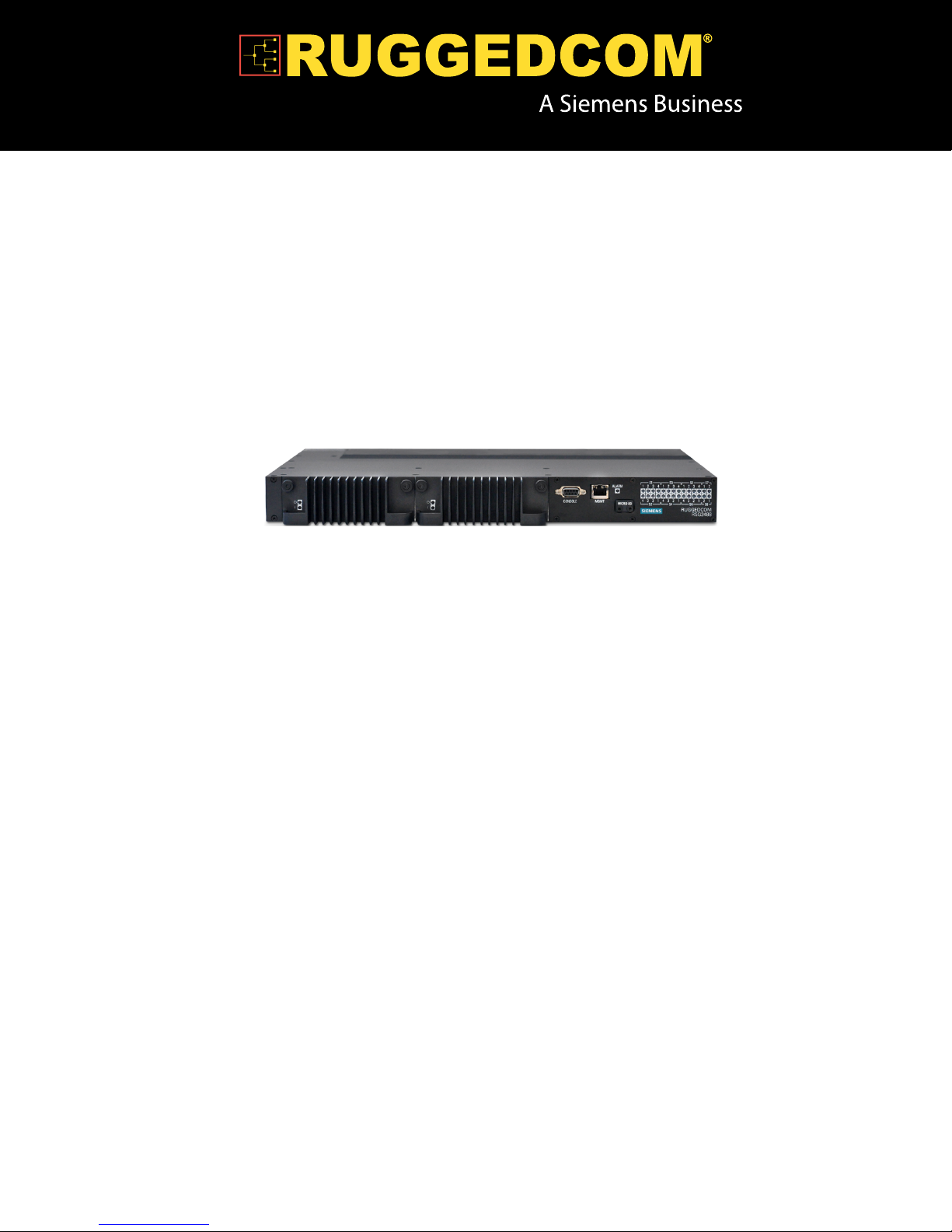
RUGGEDCOM RSG2488
Installation Guide
April 5, 2013
www.RuggedCom.com
Page 2

RUGGEDCOM RSG2488
Installation Guide
Copyright © 2013 RuggedCom Inc.
All rights reserved. Dissemination or reproduction of this document, or evaluation and communication of its contents, is not authorized
except where expressly permitted. Violations are liable for damages. All rights reserved, particularly for the purposes of patent application or
trademark registration.
This document contains proprietary information, which is protected by copyright. All rights are reserved. No part of this document may be
photocopied, reproduced or translated to another language without the prior written consent of RuggedCom Inc.
Disclaimer Of Liability
RuggedCom has verified the contents of this manual against the hardware and/or software described. However, deviations between the
product and the documentation may exist.
RuggedCom shall not be liable for any errors or omissions contained herein or for consequential damages in connection with the furnishing,
performance, or use of this material.
The information given in this document is reviewed regularly and any necessary corrections will be included in subsequent editions. We
appreciate any suggested improvements. We reserve the right to make technical improvements without notice.
Registered Trademarks
RuggedServer™, RuggedWireless™, RuggedCom Discovery Protocol (RCDP)™, RuggedExplorer™, Enhanced Rapid Spanning Tree
Protocol (eRSTP)™, ROX™, Rugged Operating System On Linux™, RuggedBackbone™, CrossBow™ and eLAN™ are trademarks of
RuggedCom Inc. Rugged Operating System (ROS)® and RuggedSwitch® are registered trademarks of RuggedCom Inc.
Other designations in this manual might be trademarks whose use by third parties for their own purposes would infringe the rights of the
owner.
Contacting RuggedCom
Corporate Headquarters US Headquarters Europe Headquarters
RuggedCom Inc.
300 Applewood Crescent
Concord, Ontario
Canada, L4K 5C7
Toll-free: 1 888 264 0006
Tel: +1 905 856 5288
Fax: +1 905 856 1995
E-mail: RuggedSales@RuggedCom.com
Web: www.RuggedCom.com
RuggedCom
1930 Harrison St., Suite 209
Hollywood, Florida
USA, 33020
Toll-free: 1 888 264 0006
Tel: +1 954 922 7938 ext. 103
Fax: +1 954 922 7984
RuggedCom
Unit 41, Aztec Centre,
Aztec West, Almondsbury, Bristol
United Kingdom, BS32 4TD
Tel: +44 1454 203 404
Fax: +44 1454 203 403
ii
Page 3

RUGGEDCOM RSG2488
Installation Guide
RUGGEDCOM RSG2488
Table of Contents
Preface ................................................................................................................ v
Alerts .................................................................................................................................................. v
Related Documents ............................................................................................................................. v
Accessing Documentation ................................................................................................................... vi
Training .............................................................................................................................................. vi
Customer Support .............................................................................................................................. vi
Chapter 1
Introduction .......................................................................................................... 1
1.1 Feature Highlights ........................................................................................................................ 1
1.2 Configuration Ports and Indicator LEDs ......................................................................................... 1
Chapter 2
Installing the Device ............................................................................................ 3
2.1 Mounting the Device .................................................................................................................... 3
2.1.1 Mounting the Device to a Rack .......................................................................................... 4
2.1.2 Mounting the Device on a DIN Rail .................................................................................... 5
2.1.3 Mounting the Device to a Panel ......................................................................................... 5
2.2 Installing/Removing Power Supplies .............................................................................................. 6
2.2.1 Installing the Power Supplies ............................................................................................. 7
2.2.2 Removing the Power Supplies ........................................................................................... 7
2.2.3 Wiring Power Supply Terminal Blocks ................................................................................. 8
2.3 Connecting the Failsafe Alarm Relay ........................................................................................... 10
2.4 Grounding the Device ................................................................................................................. 11
2.5 Cabling Recommendations ......................................................................................................... 11
2.5.1 Protection On Twisted-Pair Data Ports .............................................................................. 12
2.5.2 Gigabit Ethernet 1000Base-TX Cabling Recommendations ................................................. 12
2.6 Connecting to the Device ........................................................................................................... 13
Chapter 3
Modules .............................................................................................................. 15
3.1 Available Modules ...................................................................................................................... 15
3.2 Installing/Removing Modules ....................................................................................................... 17
3.2.1 Installing Modules ............................................................................................................ 17
3.2.2 Removing Modules .......................................................................................................... 18
iii
Page 4

RUGGEDCOM RSG2488
3.3 Installing/Removing SFP Optical Ports ......................................................................................... 18
3.3.1 Installing an SFP Optical Port .......................................................................................... 19
3.3.2 Removing an SFP Optical Port ......................................................................................... 19
Chapter 4
RUGGEDCOM RSG2488
Installation Guide
Technical Specifications ..................................................................................... 21
4.1 Power Supply Specifications ....................................................................................................... 21
4.2 Failsafe Relay Specifications ...................................................................................................... 21
4.3 Port Specifications ...................................................................................................................... 22
4.4 Supported Networking Standards ................................................................................................ 23
4.5 Operating Environment ............................................................................................................... 23
4.6 Mechanical Specifications ........................................................................................................... 24
4.7 Pin Assignments ........................................................................................................................ 24
Chapter 5
Dimension Drawings .......................................................................................... 27
Chapter 6
Certification ........................................................................................................ 31
6.1 Agency Approvals ...................................................................................................................... 31
6.2 FCC Compliance ........................................................................................................................ 31
6.3 EMI and Environmental Tests ..................................................................................................... 32
iv
Page 5
RUGGEDCOM RSG2488
Installation Guide
Preface
This guide describes the RUGGEDCOM RSG2488. It describes the major features of the device, installation,
commissioning and important technical specifications.
It is intended for use by network technical support personnel who are responsible for the installation,
commissioning and maintenance of the device. It is also recommended for use by network and system planners,
system programmers, and line technicians.
Alerts
The following types of alerts are used when necessary to highlight important information.
DANGER!
DANGER alerts describe imminently hazardous situations that, if not avoided, will result in death or
serious injury.
Preface
WARNING!
WARNING alerts describe hazardous situations that, if not avoided, may result in serious injury and/or
equipment damage.
CAUTION!
CAUTION alerts describe hazardous situations that, if not avoided, may result in equipment damage.
IMPORTANT!
IMPORTANT alerts provide important information that should be known before performing a procedure
or step, or using a feature.
NOTE
NOTE alerts provide additional information, such as facts, tips and details.
Related Documents
Other documents that may be of interest include:
• ROS User Guide for RSG2488
Alerts v
Page 6

Preface
RUGGEDCOM RSG2488
Installation Guide
Accessing Documentation
The latest Hardware Installation Guides and Software User Guides for most RuggedCom products are available
online at www.RuggedCom.com. Software User Guides for previous releases are also available.
For any questions about the documentation or for assistance finding a specific document, contact a RuggedCom
Sales representative.
Training
RuggedCom offers a wide range of educational services ranging from in-house training of standard courses
on networking, Ethernet switches and routers, to on-site customized courses tailored to the customer's needs,
experience and application.
RuggedCom's Educational Services team thrives on providing our customers with the essential practical skills to
make sure users have the right knowledge and expertise to understand the various technologies associated with
critical communications network infrastructure technologies.
RuggedCom's unique mix of IT/Telecommunications expertise combined with domain knowledge in the
utility, transportation and industrial markets, allows RuggedCom to provide training specific to the customer's
application.
For more information about training services and course availability, visit www.RuggedCom.com or contact a
RuggedCom Sales representative.
Customer Support
Customer support is available 24 hours, 7 days a week for all RuggedCom customers. For technical support or
general information, please contact Customer Support at:
Toll Free (North America): 1 866 922 7975
International: +1 905 856 5288
E-Mail: Support@RuggedCom.com
Online: www.RuggedCom.com
vi Accessing Documentation
Page 7

RUGGEDCOM RSG2488
Installation Guide
Introduction
The RSG2488 is a utility grade, fully managed, industrial Ethernet switch designed to operate reliably in harsh
environments. With rugged metal enclosure and an optional conformal coating, the RSG2488 provides a high
level of immunity to electromagnetic interference and heavy electrical surges, and can withstand temperatures
between -40 and 85 °C (-40 and 185 °F).
Highly modular, the RSG2488 switch supports up to 28 electrical and/or optical interfaces with data transfer rates
of 10/100/1000 Mbit/s. This makes it the ideal industry-standard switch for constructing electrical and/or optical
line, ring and star topologies.
Section 1.1
Feature Highlights
Chapter 1
Introduction
• Simple plug and play operation with automatic learning, negotiation and crossover detection
• MSTP 802.1Q-2005
• RSTP (802.1w) and Enhanced Rapid SpanningTree (eRSTP™) network fault recovery (<1ms)
• Quality of service (802.1p) for real-time traffic
• VLAN (802.1Q) with double tagging
• Port rate limiting and broadcast storm limiting
• Port configuration, status, statistics, mirroring, security
• SNTP time synchronization (client and server)
• Web-based, Telnet and CLI management interfaces
• SNMP (Simple Network Management Protocol) v1/v2/v3 (56-bit encryption)
• Rich set of diagnostics with logging and alarms
Section 1.2
Configuration Ports and Indicator LEDs
The RSG2488 features various ports and indicator LEDs on the front panel for configuring and troubleshooting
the device.
Feature Highlights 1
Page 8
Chapter 1
2 3 511
4
6
Introduction
RUGGEDCOM RSG2488
Installation Guide
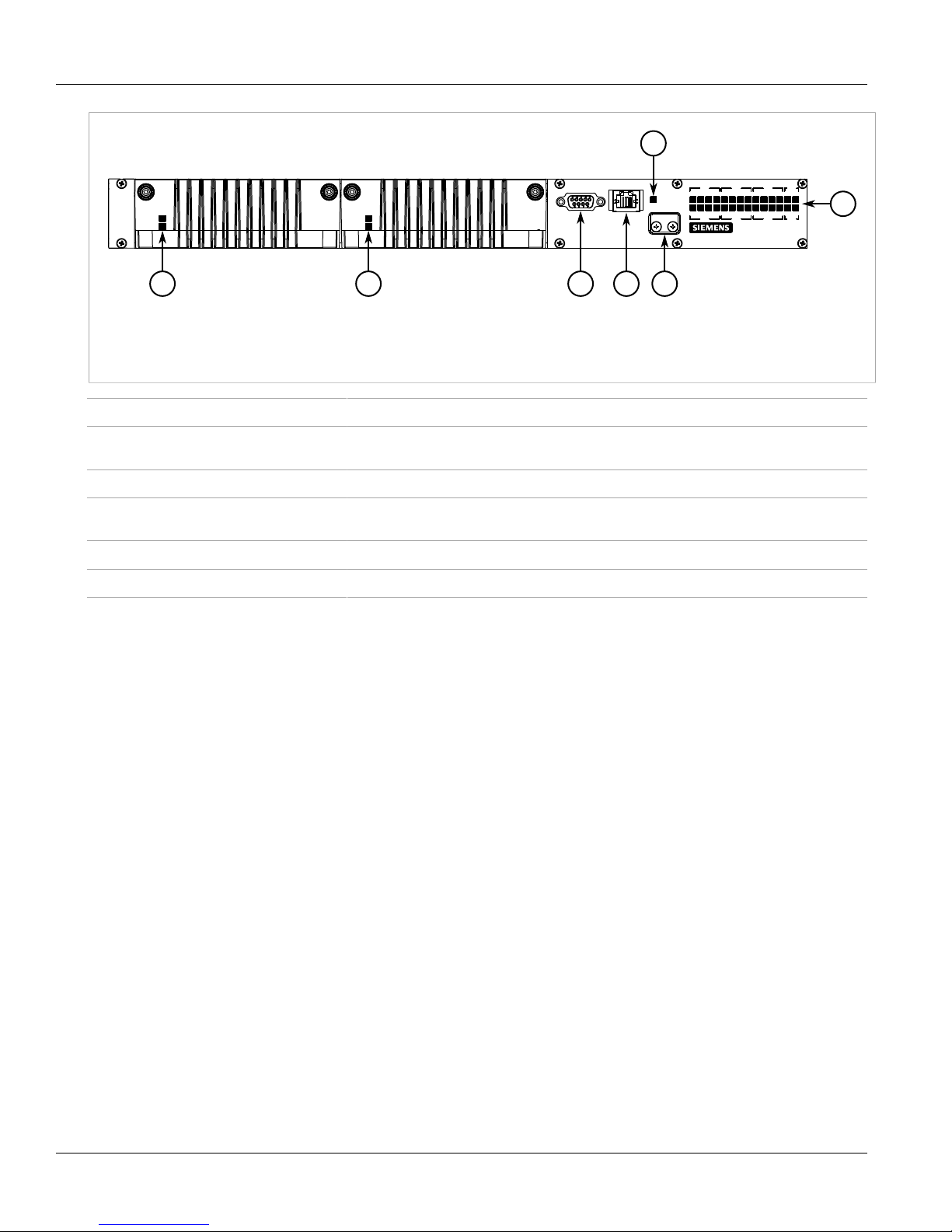
Figure 1: Front Panel
1. Power Module Indicator LEDs 2. RS232 Serial Console Port 3. Management Port 4. Alarm Indicator LED 5. MicroSD Port
6. Port Status Indicator LEDs
RS232 Serial Console Port This port is for interfacing directly with the device and access initial management functions.
Management Port This 10/100Base-T Ethernet port is used for system management that is out-of-band from
the switch fabric.
Alarm Indicator LED The alarm indicator LED illuminates when an alarm condition exists.
Power Module Indicator LEDs These LEDs indicate the status of the power modules. The top LED indicates the power
supply is supplying power. The bottom LED indicates the power supply is receiving power.
Port Status Indicator LEDs These LEDs indicate when ports are active.
MicroSD Port This port houses the microSD card containing the firmware and configuration for the device.
2 Configuration Ports and Indicator LEDs
Page 9
RUGGEDCOM RSG2488
Installation Guide
Installing the Device
Installing the Device
This section describes how to install the device, including mounting the device, installing/removing modules,
connecting power, and connecting the device to the network.
WARNING!
Radiation hazard — risk of serious personal injury. This product contains a laser system and is
classified as a CLASS 1 LASER PRODUCT. Use of controls or adjustments or performance of
procedures other than those specified herein may result in hazardous radiation exposure.
WARNING!
Electrocution hazard — risk of serious personal injury. Before performing any maintenance tasks,
make sure all power to the device has been disconnected and wait approximately 2 minutes for any
remaining energy to dissipate.
Chapter 2
IMPORTANT!
This product contains no user-serviceable parts. Attempted service by unauthorized personnel shall
render all warranties null and void.
Changes or modifications not expressly approved by RuggedCom Inc. could invalidate specifications,
test results, and agency approvals, and void the user's authority to operate the equipment.
IMPORTANT!
This product should be installed in a restricted access location where access can only be gained by
service personnel or users who have been instructed about the reasons for the restrictions applied to
the location and about any precautions that shall be taken; and access is through the use of a tool or
lock and key, or other means of security, and is controlled by the authority responsible for the location.
• Section 2.1, “Mounting the Device”
• Section 2.2, “Installing/Removing Power Supplies”
• Section 2.3, “Connecting the Failsafe Alarm Relay”
• Section 2.4, “Grounding the Device”
• Section 2.5, “Cabling Recommendations”
• Section 2.6, “Connecting to the Device”
Section 2.1
Mounting the Device
The RSG2488 is designed for maximum mounting and display flexibility. It can be ordered with connectors that
allow it to be installed in a 48 cm (19 in) rack, 2.5 cm (1 in) DIN rail, or directly on a panel.
Mounting the Device 3
Page 10
Chapter 2
33
21
Installing the Device
RUGGEDCOM RSG2488
Installation Guide
NOTE
For detailed dimensions of the device with either rack, DIN rail or panel hardware installed, refer to
Chapter 5, Dimension Drawings.
The following sections describe the various methods of mounting the device:
• Section 2.1.1, “Mounting the Device to a Rack”
• Section 2.1.2, “Mounting the Device on a DIN Rail”
• Section 2.1.3, “Mounting the Device to a Panel”
Section 2.1.1
Mounting the Device to a Rack
For rack mount installations, the RSG2488 can be ordered with rack mount adaptors pre-installed at the front or
rear of the chassis. Additional adaptors are provided to further secure the device in high-vibration or seismically
active locations.
To secure the device to a standard 48 cm (19 in) rack, do the following:
1. Make sure the rack mount adaptors are installed on the correct side of the chassis.
• To make the modules and ports accessible, install the rack mount adaptors at the rear of the chassis
• To make the management ports and LEDs accessible, install the rack mount adaptors at the front of the
chassis
NOTE
The chassis features multiple mounting holes, allowing the rack mount adaptors to be installed up
to 25 mm (1 in) from the face of the device.
Figure 2: Rack Mount Adaptors
1. Rear 2. Front 3. Rack Mount Adaptor
2. If required, install adaptors on the opposite side of the device to protect from vibrations.
3. Insert the device into the rack.
NOTE
Since heat within the device is channeled to the enclosure, it is recommended that 1 rack-unit
of space, or 44 mm (1.75 in), be kept empty above the device. This allows a small amount of
convectional airflow.
Forced airflow is not required. However, any increase in airflow will result in a reduction of ambient
temperature and improve the long-term reliability of all equipment mounted in the rack space.
4. Secure the adaptors to the rack using the supplied hardware.
4 Mounting the Device to a Rack
Page 11

RUGGEDCOM RSG2488
3
1
1
2
2
Installation Guide
Section 2.1.2
Installing the Device
Mounting the Device on a DIN Rail
For panel installations, the RSG2488 can be ordered with panel/DIN rail adaptors pre-installed on each side of
the chassis. The adaptors allow the device to be attached to a panel using screws.
To mount the device to a panel, do the following:
1. Align the adaptors with the DIN rails and slide the device into place.
Chapter 2
Figure 3: DIN Rail Mounting
1. DIN Rail 2. Panel/DIN Rail Adaptor 3. Screw
2. Install one of the supplied screws on either side of the device to secure the adaptors to the DIN rails.
Section 2.1.3
Mounting the Device to a Panel
For panel installations, the RSG2488 can be ordered with panel/DIN rail adaptors pre-installed on each side of
the chassis. The adaptors allow the device to be attached to a panel using screws.
To mount the device to a panel, do the following:
1. Place the device against the panel and align the adaptors with the mounting holes.
Mounting the Device on a DIN Rail 5
Page 12
Chapter 2
2
1
1
Installing the Device
RUGGEDCOM RSG2488
Installation Guide
Figure 4: Panel Mounting
1. Screw 2. Panel/DIN Rail Adaptor
2. Install the supplied screws to secure the adaptors to the panel.
Section 2.2
Installing/Removing Power Supplies
The RSG2488 supports dual redundant AC and/or DC power supplies that can be installed in any combination.
IMPORTANT!
• In a high AC/DC and low DC (24/48 V) power supply arrangement, either power supply can be
installed in slot PM1 or PM2. However, if a high AC/DC power supply is installed in slot PM1, the
high AC/DC wiring must be connected to the high terminal block PM1 terminals. If a low DC power
supply is installed in slot PM1, the loww DC wiring must be made to the low terminal block PM1
terminals. High voltage wiring is always made to the upper Hi terminal block and low voltage (24/48
V) wiring is always made to the lower Lo terminal block.
• Use only #16 gauge wiring when connecting terminal blocks.
• A circuit breaker rated no higher than 20 A must be installed between the device and the supply
mains.
• Whenever possible, use a separate circuit breaker for each power supply.
• For maximum redundancy in a dual power supply configuration, use two independent power
sources.
6 Installing/Removing Power Supplies
Page 13

RUGGEDCOM RSG2488
2
3
1
Installation Guide
Installing the Device
• The socket outlet/disconnect device must be installed near the device and be easily accessible.
• Equipment must be installed according to applicable local wiring codes and standards.
The following sections describe how to install, remove and wire the power supplies:
• Section 2.2.1, “Installing the Power Supplies”
• Section 2.2.2, “Removing the Power Supplies”
• Section 2.2.3, “Wiring Power Supply Terminal Blocks”
Section 2.2.1
Installing the Power Supplies
To install the power supplies, do the following:
1. Make sure power to the device has been disconnected and wait approximately two minutes for any
remaining energy to dissipate.
2. Remove the dust cover or, if equipped, the currently installed power supply. For information about removing
power supplies, refer to Section 2.2.2, “Removing the Power Supplies”.
3. Insert the power supply into the empty slot.
Chapter 2
Figure 5:
1. Screws 2. Power Supply 3. Slot
4. Hand-tighten the screws to secure the module.
5. If necessary, connect the required terminal block to the chassis. For more information, refer to Section 2.2.3,
“Wiring Power Supply Terminal Blocks”.
6. Supply power to the device. The top and bottom LEDs on the power supply should be green, indicating that
power is being received and supplied to the device.
Section 2.2.2
Removing the Power Supplies
To remove the power supplies, do the following:
Installing the Power Supplies 7
Page 14

Chapter 2
2
3
1
2
1
Installing the Device
1. Make sure power to the device has been disconnected and wait approximately two minutes for any
remaining energy to dissipate.
2. Unscrew the power supply(ies) from the chassis.
3. Pull the power supply(ies) from the chassis.
Figure 6:
1. Screws 2. Power Supply 3. Slot
RUGGEDCOM RSG2488
Installation Guide
4. Install a cover(s) over the empy slot to prevent the ingress of dust and dirt.
Section 2.2.3
Wiring Power Supply Terminal Blocks
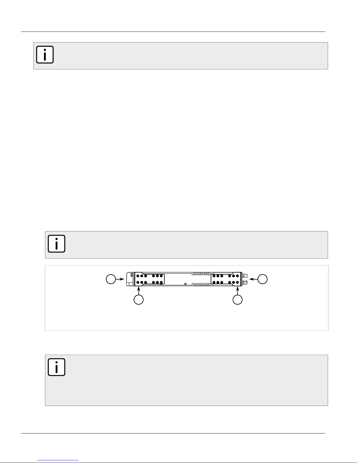
The RSG2488 can be equipped with screw-type or insulated terminal blocks for high or low AC/DC power input.
Connect the terminal blocks to the HI and LO terminal ports on the rear face of the device.
Figure 7: Terminal Ports
1. LO Input 2. HI/HIP Input
NOTE
The screw-type terminal block is installed using Philips screws and compression plates, allowing either
bare wire connections or crimped terminal lugs. Use #6 size ring lugs for secure, reliable screws, which
must be removed to make connections.
8 Wiring Power Supply Terminal Blocks
Page 15

RUGGEDCOM RSG2488
43
2
43
1
+
+
+
Installation Guide
CAUTION!
Electrical hazard — risk of damage to the device. Do not connect AC power cables to a DC power
supply terminal block. Damage to the power supply may occur.
Connectors for Power Modules
WARNING!
Electrocution hazard — risk of serious personal injury and/or damage to the device. Make sure the
supplied cover is always installed over the HI/HIP terminal block.
Installing the Device
Chapter 2
Figure 8: Power Supply Terminal Blocks
1. Insulated Terminal Block for HIP Power Modules 2. Screw-Type Terminal Block for HI Power Modules 3. Connectors for HI and HIP
Power Modules 4. Connectors for 24, 24P, 48, and 48P Power Modules
Wiring Examples
Figure 9: Single AC Power Supply Wiring
Wiring Power Supply Terminal Blocks 9
Figure 10: Dual AC Power Supply Wiring
Page 16

Chapter 2
+
+
+
+
+
Installing the Device
RUGGEDCOM RSG2488
Installation Guide
Figure 11: Single DC Power Supply Wiring
Figure 12: Dual DC Power Supply Wiring
Figure 13: Dual AC/DC Power Supply Wiring
Section 2.3
Connecting the Failsafe Alarm Relay
The failsafe relay is provided to identify criticial error conditions. The contacts are energized when the device is
powered-up and remain energized unless a critical error occurs.
The following shows the proper relay connections.
10 Connecting the Failsafe Alarm Relay
Page 17

RUGGEDCOM RSG2488
3
2
1
3
1
2
Installation Guide
Figure 14: Failsafe Alarm Relay Wiring
1. Normally Open 2. Common 3. Normally Closed
Installing the Device
Control of the failsafe relay output is configurable through the Rugged Operating System (ROS) software. One
common application for this relay is to signal an alarm if a power failure.
Chapter 2
Section 2.4
Grounding the Device
The RSG2488 chassis ground connection uses a #6-32 screw. It is recommended to terminate the ground
connection with a #6 ring or spade lug and torque it to 1.7 Nm (15 lbf-in).
Figure 15: Chassis Ground Connection
1. #6-32 Screw 2. Stainless Steel Standoff 3. #6 Ring Lug
Section 2.5
Cabling Recommendations
Before connecting the device, be aware of the recommendations and considerations outlined in the following
sections:
• Section 2.5.1, “Protection On Twisted-Pair Data Ports”
Grounding the Device 11
Page 18

Chapter 2
Installing the Device
RUGGEDCOM RSG2488
Installation Guide
• Section 2.5.2, “Gigabit Ethernet 1000Base-TX Cabling Recommendations”
Section 2.5.1
Protection On Twisted-Pair Data Ports
RuggedCom does not recommend the use of copper cabling of any length for critical, real-time substation
automatation applications. All copper Ethernet ports on RuggedCom products include transient suppression
circuitry to protect against damage from electrical transients and conform with IEC 61850-3 and IEEE 1613 Class
1 standards. This means that during a transient electrical event, communications erorrs or interruptions may
occur, but recovery is automatic.
RuggedCom also does not recommend using copper Ethernet ports to interface with devices in the field across
distances that could produce high levels of ground potential rise (i.e. greater than 2500 V), during line-to-ground
fault conditions.
Section 2.5.2
Gigabit Ethernet 1000Base-TX Cabling Recommendations
The IEEE 802.3ab Gigabit Ethernet standard defines 1000 Mbit/s Ethernet communications over distances of
up to 100 m (328 ft) using all 4 pairs in category 5 (or higher) balanced, unshielded twisted-pair cabling. For
wiring guidelines, system designers and integrators should refer to the Telecommunications Industry Association
(TIA) TIA/EIA-568-A wiring standard that characterizes minimum cabling performance specifications required
for proper Gigabit Ethernet operation. To ensure reliable, error-free data communication, new and pre-existing
communication paths should be verified for TIA/EIA-568-A compliance.
The following table summarizes the relevant cabling standards:
Table 1: Cabling Categories and 1000Base-TX Compliance
Cabling Category
< 5 No New wiring infrastructure required.
5 Yes Verify TIA/EIA-568-A compliance.
5e Yes No action required. New installations should be designed with Category 5e or higher.
6 Yes No action required.
> 6 Yes Connector and wiring standards to be determined.
1000Base-
TX Compliant
Required Action
Follow these recommendations for copper data cabling in high electrical noise environments:
• Data cable lengths should be as short as possible, preferrably 3 m (10 ft) in length. Copper data cables should
not be used for inter-building communications.
• Power and data cables should not be run in parallel for long distances, and should be installed in separate
conduits. Power and data cables should intersect at 90° angles when necessary to reduce inductive coupling.
• Shielded/screened cabling can be used when required. The cable shield should be grounded at one single
point to avoid the generation of ground loops.
12 Protection On Twisted-Pair Data Ports
Page 19

RUGGEDCOM RSG2488
1
Installation Guide
Section 2.6
Installing the Device
Connecting to the Device
The RS232 serial console port on the front of the RSG2488 device provides access to the boot-time control and
configuration menu interface, as well as a console connection to the ROS™ Web interface.
Figure 16: Serial Console Port
1. RS232 Serial Console Port
Chapter 2
Use the following settings when attempting to connect to the device through the serial console port:
• 57600 bps
• 8 bits
• No parity
• 1 stop bit
Connecting to the Device 13
Page 20

Chapter 2
Installing the Device
RUGGEDCOM RSG2488
Installation Guide
14 Connecting to the Device
Page 21

RUGGEDCOM RSG2488
4
4
4
4
4
4
4
4
3 3
2
1
Installation Guide
Modules
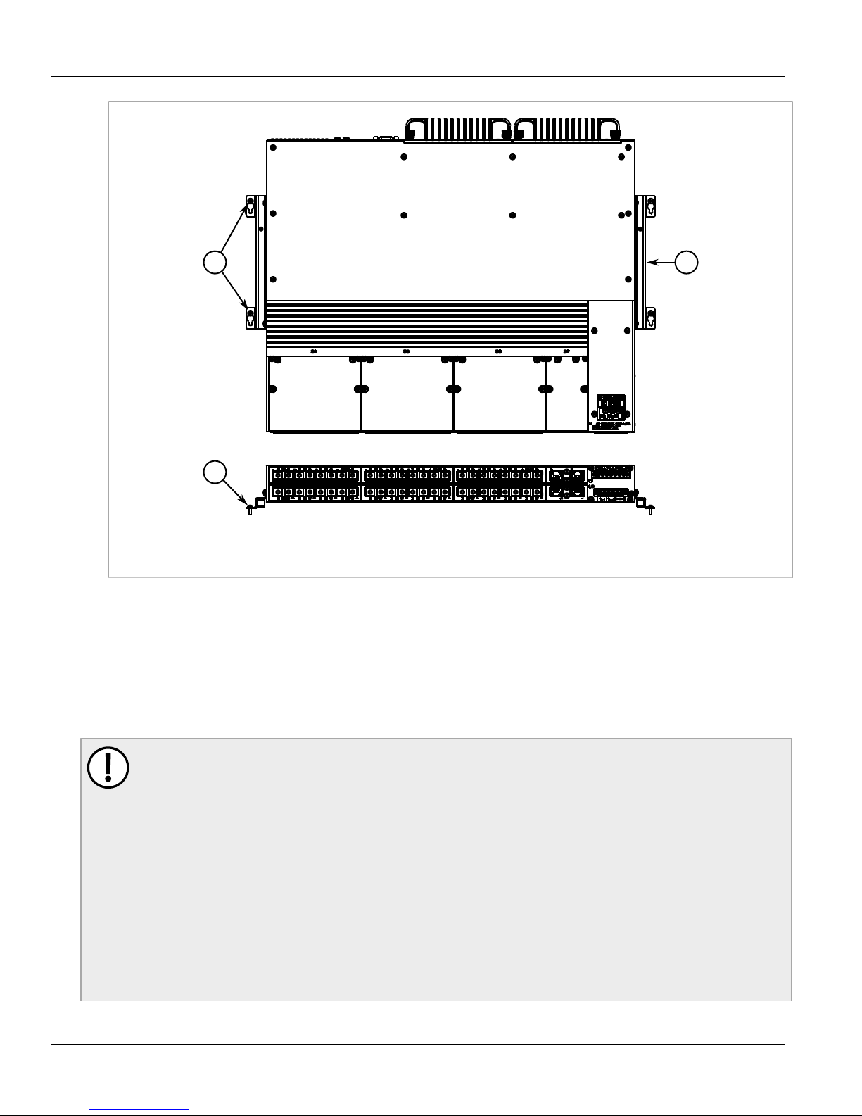
The RSG2488 can be equipped with multiple modules to enhance its abilities and performance. Each type of
module has a specific location in the RSG2488 chassis.
Chapter 3
Modules
Figure 17: Module Assignment
1. Front Panel 2. Rear Panel 3. Power Module Slots 4. Ethernet Module Slots
The following sections describe the available modules and how to install/remove them:
• Section 3.1, “Available Modules”
• Section 3.2, “Installing/Removing Modules”
• Section 3.3, “Installing/Removing SFP Optical Ports”
Section 3.1
Available Modules
The RSG2488 supports eight line modules. Several types of line modules may be ordered, depending on the
type, speed and number of Ethernet ports required.
The following illustrations show the typical port configurations and connectors available for RSG2488 line
modules. For complete information on the available line modules, refer to the RUGGEDCOM RSG2488 data
sheet available at www.RuggedCom.com.
Available Modules 15
Page 22

Chapter 3
Modules
Ethernet - Copper
RUGGEDCOM RSG2488
Installation Guide
Figure 18: 4 Port RJ45
Figure 20: 4 Port FastConnect RJ45
Ethernet - Fiber
Figure 22: 4 Port LC
Figure 19: 2 Port RJ45
Figure 21: 2 Port FastConnect RJ45
Figure 23: 4 Port SC
Figure 24: 4 Port ST
SFP Optics Modules
Figure 25: 4 Port SFP
16 Available Modules
Figure 26: 2 Port SFP
Page 23

RUGGEDCOM RSG2488
3
1
2
Installation Guide
Section 3.2
Installing/Removing Modules
The following sections describe how to install and remove modules:
• Section 3.2.1, “Installing Modules”
• Section 3.2.2, “Removing Modules”
Section 3.2.1
Installing Modules
Upon installing a new module in the device, all the features associated to the module are available in the
operating system. For more information, refer to the ROS User Guide for the RSG2488.
To install a module, do the following:
1. Make sure power to the device has been disconnected and wait approximately two minutes for any
remaining energy to dissipate.
2. If the device is installed in a rack, remove it from the rack.
3. Remove the current module from the slot. For more information, refer to Section 3.2.2, “Removing Modules”.
4. Insert the new module into the slot.
Chapter 3
Modules
Figure 27: Installing a Module
1. Module 2. Chassis 3. Screw
5. Hand-tighten the screws to secure the module to the chassis.
6. If necessary, install the device in the rack.
7. Connect power to the device.
Installing/Removing Modules 17
Page 24

Chapter 3
3
1
2
Modules
Section 3.2.2
RUGGEDCOM RSG2488
Installation Guide
Removing Modules
Once a module is removed, all the features associated with the module are hidden or disabled in the operating
system.
To remove a module, do the following:
1. Make sure power to the device has been disconnected and wait approximately two minutes for any
remaining energy to dissipate.
2. If the device is installed in a rack, remove it from the rack.
3. Loosen the screws that secure the module to the chassis.
4. Pull the module from the chassis to disconnect it.
Figure 28: Removing a Module
1. Module 2. Chassis 3. Screw
5. Install a new module or a blank module (to prevent the ingress of dust and dirt). For more information, refer
to Section 3.2.1, “Installing Modules”.
6. If necessary, install the device in the rack.
7. Connect power to the device.
Section 3.3
Installing/Removing SFP Optical Ports
The RSG2488 can be ordered with SFP (Small Form-factor Pluggable) optics modules. The optical ports in these
modules can be safely inserted and removed while the chassis is powered and operating.
The following sections describe how to install and remove SFP optical ports:
• Section 3.3.1, “Installing an SFP Optical Port”
18 Removing Modules
Page 25

RUGGEDCOM RSG2488
2
1
Installation Guide
• Section 3.3.2, “Removing an SFP Optical Port”
Section 3.3.1
Installing an SFP Optical Port
To install an SFP optical port, do the following:
CAUTION!
Electrical hazard – risk of damage to equipment. Use only components certified by RuggedCom with
RuggedCom products. Damage to the module and device may occur if compatibility and reliability have
not been properly assessed.
CAUTION!
Electrical hazard – risk of damage to equipment. Make sure all electrostatic energy is dissipated
before installing or removing components from the device. An electrostatic discharge (ESD) can cause
serious damage to the component once it is outside the chassis.
1. Make sure all potential electrostatic build-up has been propery discharged to prevent electrostatic discharges
(ESD). This can be accomplished by wearing an ESD wrist strap or by touching Earth or the chassis ground.
2. Remove the dust cover from the port slot and insert the port.
Chapter 3
Modules
Figure 29: Installing an SFP Optical Port
1. SFP Optical Port 2. Metal Bail-Latch
3. Connect a cable to port and test the connection.
Section 3.3.2
Removing an SFP Optical Port
To remove an SFP optical port, do the following:
CAUTION!
Electrical hazard – risk of damage to equipment. Make sure all electrostatic energy is dissipated before
performing installing or removing components from the device. An electrostatic discharge (ESD) can
cause serious damage to the component once it is outside the chassis.
1. Make sure all potential electrostatic build-up has been propery discharged to prevent electrostatic discharges
(ESD). This can be accomplished by wearing an ESD wrist strap or by touching Earth or the chassis ground.
2. Disconnect the cable from the port.
Installing an SFP Optical Port 19
Page 26

Chapter 3
2
1
Modules
RUGGEDCOM RSG2488
Installation Guide
3. Grab the metal bail-latch on the port and remove the port from the module.
Figure 30: Removing an SFP Optical Port
1. SFP Optical Port 2. Metal Bail-Latch
4. Immediately insert a dust cover in the empty port slot to prevent the ingress of dust and dirt.
5. Store the port in an ESD-safe bag or other suitable ESD-safe environment, free from moisture and stored at
the proper temperature (-40 to 85 °C or -40 to 85 °F).
20 Removing an SFP Optical Port
Page 27

RUGGEDCOM RSG2488
Installation Guide
Technical Specifications
Technical Specifications
The following sections provide important technical specifications related to the device and available modules:
• Section 4.1, “Power Supply Specifications”
• Section 4.2, “Failsafe Relay Specifications”
• Section 4.3, “Port Specifications”
• Section 4.4, “Supported Networking Standards”
• Section 4.5, “Operating Environment”
• Section 4.6, “Mechanical Specifications”
• Section 4.7, “Pin Assignments”
Chapter 4
Section 4.1
Power Supply Specifications
Table 2: Power Supply Specifications
Power Supply Type
24 VDC (Single) 13 VDC 36 VDC 10 A 40 W
48 VDC (Single) 38 VDC 72 VDC 7 A 40 W
High Voltage AC/DC
a
Power consumption varies based on configuration. 10/100Base-TX ports consume roughly 1W less than fiber optic ports.
Section 4.2
Min Max
100 VDC 300 VDC 80 W
88 VAC 264 VAC
Input Range
Internal Fuse Rating
Failsafe Relay Specifications
IMPORTANT!
The alarm switching voltage must be greater than the Safety Extra Low-Voltage (SELV) to meet safety
requirements.
3.15 A
Maximum Power
Consumption
80 W
a
Table 3: Form C Contact Relay Specifications
Parameter Value (Resistive Load)
Maximum Switching Voltage 240 VAC
Power Supply Specifications 21
Page 28

Chapter 4
Technical Specifications
Parameter Value (Resistive Load)
125 VDC
2 A @ 240 VAC
Rated Switching Current
0.15 A @ 125 VDC
2 A @ 30 VDC
RUGGEDCOM RSG2488
Installation Guide
Maximum Switching Capacity
150 W
500 VA
Section 4.3
Port Specifications
The following details the specifications for fibre optic ports that can be ordered with the RSG2488.
NOTE
• Maximum segment length is greatly dependent on factors such as fiber quality, and the number of
patches and splices. Please consult RuggedCom sales associates when determining maximum
segment distances.
• All optical power numbers are listed as dBm averages.
Table 4: Gigabit Ethernet (1 Gbps) Optical Specifications - Fixed Gigabit Transceivers
Order
Code
FG01 MM LC
Mode
Connector
Type
Cable
Type
(μm)
50/125
62.5/125
Tx λ
(typ.)
(nm)
850 -9 -2.5 -20 0 0.5 11
Tx min
(dBm)
Tx max
(dBm)
Rx
Sensitivity
(dBm)
RX
Saturation
(dBm)
Distance
(Typ.)
(km)
Power
Budget
(dB)
FG02 SM LC 9/125 1310 -10 -3 -20 -3 10 10
FG03 SM LC 9/125 1310 -9.5 -3 -21 -3 10 11.5
FXA01 MM ST
FXA02 MM SC
FXA04 SM ST 9/125 1310 -15 -8 -32 -3 20 17
FXA05 SM SC 9/125 1300 -15 -8 -31 -7 20 16
FXA11 MM LC 62.5/125 1310 -19 -14 -32 -14 2 13
62.5/125 -19 12
50/125
62.5/125 -19 12
50/125
1308
1308
-22.5
-22.5
-14 -31 -14 2
8.5
-14 -31 -14 2
8.5
Table 5: Gigabit Ethernet (1 Gbps) Optical Specifications - SFP Gigabit Transceivers
Order
Code
FG51 MM LC
Mode
Connector
Type
Cable
Type
(μm)
50/125
62.5/125
Tx λ
(typ.)
(nm)
850 -9 -2.5 -20 0 0.5 11
Tx min
(dBm)
Tx max
(dBm)
Rx
Sensitivity
(dBm)
RX
Saturation
(dBm)
Distance
(Typ.)
(km)
Power
Budget
(dB)
22 Port Specifications
Page 29

RUGGEDCOM RSG2488
Installation Guide
Technical Specifications
Chapter 4
Order
Code
FG52 SM LC 9/125 1310 -9.5 -3 -19 -3 10 9.5
FG53 SM LC 9/125 1310 -7 -3 -23 -3 25 16
FG54 SM LC 9/125 1550 0 5 -23 -3 70 23
Mode
Connector
Type
Cable
Type
(μm)
Tx λ
(typ.)
(nm)
Tx min
(dBm)
Tx max
(dBm)
Section 4.4
Supported Networking Standards
Table 6: Supported Networking Standards
Parameter 10 Mbps 100 Mbps 1000 Mbps Notes
IEEE 802.1AB Yes Yes Yes Link Layer Discovery Protocol (LLDP)
IEEE 802.1D Yes Yes Yes MAC bridges
IEEE 802.1Q Yes Yes Yes VLAN (Virtual LAN)
IEEE 802.1p Yes Yes Yes Priority levels
IEEE 802.1x Yes Yes Yes Port-based network access control
Rx
Sensitivity
(dBm)
RX
Saturation
(dBm)
Distance
(Typ.)
(km)
Power
Budget
(dB)
IEEE 802.3 Yes No No 10BaseT
IEEE 802.3u No Yes No 100BaseTX/100BaseFX
IEEE 802.3z No No Yes 1000BaseSX/LX
IEEE 802.3ab No No Yes 1000BaseTX
IEEE 802.3af Yes Yes No Power over Ethernet ports (1-6)
IEEE 802.3x Yes Yes Yes Full duplex operation
Section 4.5
Operating Environment
Table 7: Operating Environment Specifications
Parameter Range Comments
Ambient Operating Temperature -40 to 85 °C (-40 to 185 °F)
Ambient Storage Temperature -40 to 85 °C (-40 to 185 °F)
Ambient temperature as measured
from a 30 cm (11.8 in) radius
surrounding the center of the enclosure
Ambient temperature as measured
from a 30 cm (11.8 in) radius
surrounding the center of the enclosure
Ambient Relative Humidity 5% to 95%
Supported Networking Standards 23
Ambient temperature as measured
from a 30 cm (11.8 in) radius
surrounding the center of the enclosure
Page 30

Chapter 4
1
4
2
3
1 2
Technical Specifications
Section 4.6
Mechanical Specifications
Table 8: Mechanical Specifications
Parameter Value
Dimensions Refer to Chapter 5, Dimension Drawings
Weight 8.6 kg (19 lbs)
Enclosure 18 AWG Galvanized Steel
Section 4.7
Pin Assignments
RS232 Serial Console Port
RUGGEDCOM RSG2488
Installation Guide
Figure 31: RS232 Serial Console Pins
1. Pin 5 2. Pin 1 3. Pin 9 4. Pin 6
Copper Ethernet Ports
Figure 32: RJ45 Copper Ethernet Port Pins
1. Pin 1 2. Pin 8
RJ45 Pin 10/100Base-Tx 10/100/1000Base-Tx
1 RX+ A+
2 RX- A-
3 TX+ B+
4 NC C+
5 NC C-
DB9 Pin Signal Function
1 NC
2 TX
3 RX
4 NC
5 GND
6 NC
7 NC
8 NC
9 NC
24 Mechanical Specifications
6 TX- B-
7 NC D+
8 NC D-
Page 31

RUGGEDCOM RSG2488
Installation Guide
Terminal Blocks
Terminal Block Pin Description
Technical Specifications
Chapter 4
Figure 33: Terminal Block Pins
HI
LO
PS1/PS2 L+ Connected to the
(Live) terminal.
PS1/PS2 N- Connected to the
(Neutral) terminal.
Relay NO Normally open
failsafe relay contact.
Relay COM Failsafe relay
common contact.
Relay NC Normally closed
failsafe relay contact.
PS1/PS2 + Connected to the
(Live) terminal.
PS1/PS2 - Connected to the
(Neutral) terminal.
GND Connected to the
equipment ground bus.
Chassis ground connects
to both power supply
surge grounds via a
removable jumper.
Pin Assignments 25
Page 32

Chapter 4
Technical Specifications
RUGGEDCOM RSG2488
Installation Guide
26 Pin Assignments
Page 33

RUGGEDCOM RSG2488
376.0
442.4
44.0
Installation Guide
Dimension Drawings
Dimension Drawings
Chapter 5
NOTE
All dimensions are in millimeters, unless otherwise stated.
Figure 34: Overall Dimensions
27
Page 34

Chapter 5
24.4
369.8
350.2
43.9
31.8
4.7
6.4
483.5
465.2
51.1
248.4
299.5
21.1
44
Dimension Drawings
RUGGEDCOM RSG2488
Installation Guide
Figure 35: Rack Mount Dimensions
28
Page 35

RUGGEDCOM RSG2488
490.6
134.5
277.4
98.6
480.5
160.0
25.4
148.3
227.7
51.6
7.6
1
Installation Guide
Dimension Drawings
Chapter 5
Figure 36: Panel and Din Rail Mount Dimensions
1. DIN Rail Centerline
29
Page 36

Chapter 5
Dimension Drawings
RUGGEDCOM RSG2488
Installation Guide
30
Page 37

RUGGEDCOM RSG2488
Installation Guide
Certification
The RSG2488 device has been thoroughly tested to guarantee its conformance with recognized standards and
has recieved approval from recognized regulatory agencies.
• Section 6.1, “Agency Approvals”
• Section 6.2, “FCC Compliance”
• Section 6.3, “EMI and Environmental Tests”
Section 6.1
Agency Approvals
Chapter 6
Certification
The RSG2488 has received approval from various agencies.
Table 9: Agency Approvals
Agency Standards Comments
FCC FCC Part 15 Class A for USA
CE EN 55022, EN 61000-3-2, EN 61000-3-3,
EN 61000-6-2, EN 60950-1, EN 60825-1
TUV IEC 60950-1, EN 60950-1, CSA/UL 60950-1 International Safety Compliance
Industry Canada (IC) ICES-003 Class A for Canada
Section 6.2
EU directives include 2004/108/
EC (EMC Directive) and 2006/95/
EC (Low Voltage Directive)
FCC Compliance
This equipment has been tested and found to comply with the limits for a Class A digital device pursuant to Part
15 of the FCC Rules. These limits are designed to provide reasonable protection against harmful interference
when the equipment is operated in a commercial environment.
This equipment generates, uses and can radiate radio frequency energy and, if not installed and used in
accordance with the instruction manual, may cause harmful interference to radio communications. Operation of
this equipment in a residential area is likely to cause harmful interference in which case the user will be required
to correct the interference on his own expense.
Agency Approvals 31
Page 38

Chapter 6
Certification
Section 6.3
EMI and Environmental Tests
The RSG2488 has passed the following EMI and environmental tests.
Table 10: IEC 61850-3 EMI Type Tests
Test Description Test Levels Severity Levels
RUGGEDCOM RSG2488
Installation Guide
IEC 61000-4-2 ESD
IEC 61000-4-3 Radiated RFI Enclosure Ports 20 Vm X
IEC 61000-4-4 Burst (Fast Transient)
IEC 61000-4-6 Induced (Conducted) RFI
IEC 61000-4-8 Magnetic Field Enclosure Ports
IEC 61000-4-29
Voltage Dips and
Interrupts (D C.
Power Ports)
Enclosure Contact +/- 8 kV
Enclosuer Air +/- 15 kV
Signal Ports +/- 4 kV @ 2.5 kHz X
D.C. Power Ports
A.C. Power Ports
Earth Ground Ports
Signal Ports
D.C. Power Ports
A.C. Power Ports
Earth Ground Ports
D.C. Power Ports
A.C. Power Ports
+/- 4 kV 4
10 V 3
40 A/m, continuous,
1000 A/m for 1 s
30% for 0.1 s
60% for 0.1 s
100% for 0.05 s
30% for 1 period
60% for 50 periods
4
IEC 61000-4-11
IEC 61000-4-16 Mains Frequency Voltage
IEC 61000-4-17
IEC 60255-5
Voltage Dips and
Interrupts (A. C.
Power Ports)
Ripple on D.C.
Power Supply
Dialiectric Strength
A.C. Power Ports
Signal Ports
D.C. Power PortsIEC 61000-4-12 Damped Oscillatory
A.C. Power Ports
Signal Ports
D.C. Power Ports
D.C. Power Ports 10% 3
Signal Ports
D.C. Power Ports 1.5 kVDC
A.C. Power Ports 2 kVAC
100% for 5 periods
100% for 50 periods
2.5kV common, 1kV
diff. mode@1MHz
30 V Continuous,
300 V for 1s
2 kVAC (Fail-
Safe Relay Output)
3
4
32 EMI and Environmental Tests
Page 39

RUGGEDCOM RSG2488
Installation Guide
Chapter 6
Certification
Test Description Test Levels Severity Levels
IEC 1613/C37.90
IEC 1613/C37.90.1
H.V. Impulse
Dialiectric Strength
H.V. Impulse
Oscillatory
Fast Transient
Signal Ports
D.C. Power Ports
A.C. Power Ports
Signal Ports
D.C. Power Ports 5 kV
A.C. Power Ports 5 kV
Signal Ports 2 kVAC
D.C. Power Ports 1.5 kVDC
A.C. Power Ports 2 kVAC
Signal Ports
D.C. Power Ports
A.C. Power Ports
Signal Ports +/- 4 kV @ 2.5 kHz
D.C. Power Ports
A.C. Power Ports
5 kV (Fail-Safe
Relay Output)
5 kV
5 kV (Fail-Safe
Relay Output)
2.5 kV common
mode @1 MHz
2.5 kV common, 1 kV
diff. mode@1 MHz
+/- 4 kV
Earth Ground Ports
IEC 1613/C37.90.2 Radiated RFI Enclosure Ports 35 V/m
IEC 1613/C37.90.3 ESD
Enclosure Contact +/- 8 kV
Enclosure Air +/- 15 kV
NOTE
• In the case of an all fiber port configuration, this product meets all Class 2 requirements. Otherwise,
all Class 1 requirements are met for copper ports.
• If the unit contains copper ports, the IEC 1613 conformance is Class 1, during which disturbance
errors may occur but recovery is automatic.
• If the unit contains all fiber ports, the IEC1613 conformance is Class 2, during which no disturbance
errors will occur.
Table 11: Environmental Type Tests
Test Description Test Levels
IEC 60068-2-1 Cold Temperature Test Ad -40 °C (-40 °F), 16 Hours
IEC 60068-2-2 Dry Heat Test Bd 85 °C (185 °F), 16 Hours
IEC 60068-2-30 Humidity (Damp Heat, Cyclic) Test Db
95% (non-condensing),
55 °C (131 °F), 6 cycles
IEC 60068-21-1 Vibration 2g @ 10 - 150 Hz
IEC 60068-21-2 Shock 30g @ 11 mS
EMI and Environmental Tests 33
Page 40

Chapter 6
Certification
RUGGEDCOM RSG2488
Installation Guide
34 EMI and Environmental Tests
 Loading...