

Page 1
Rugged
RuggedWireless
RuggedRugged
Wireless Device Server with 2 Serial Port and/or 2 Ethernet
Wireless RS9
WirelessWireless
Ports
RS911110000W
RS9RS9
W
WW
Installation Guide
www.ruggedcom.com
RuggedCom Inc. I 30 Whitmore Road, Woodbridge, Ontario, Canada L4L 7Z4
Tel: (905) 856-5288 I Fax: (905) 856-1995 I Toll Free: (888) 264-0006
Page 2

Federal Communications Commission
Radio Frequency Interference Statement
This equipment has been tested and found to comply with the limits for a Class A digital device
pursuant to Part 15 of the FCC Rules. These limits are designed to provide reasonable protection
against harmful interference when the equipment is operated in a commercial environment. This
equipment generates, uses and can radiate radio frequency energy and, if not installed and used in
accordance with the instruction manual, may cause harmful interference to radio communications.
Operation of this equipment in a residential area is likely to cause harmful interference in which
case the user will be required to correct the interference at his expense.
Caution
This product contains a laser system and is classified as a “CLASS 1 LASER PRODUCT”.
Use of controls or adjustments or performance of procedures other than those specified herein
may result in hazardous radiation exposure. This product contains no user serviceable parts.
Attempted service by unauthorized personnel shall render all warranties null and void.
Should this device require service see the “Warranty” section of this installation guide.
Important
This unit should be installed in a restricted access location where access can only be gained by
service personnel or users who have been instructed about the reasons for the restrictions
applied to the location and about any precautions that shall be taken; and access is through the
use of a tool or lock and key, or other means of security, and is controlled by the authority
responsible for the location.
Trademarks:
Ethernet is a trademark of Xerox Corporation
RuggedSwitch, RuggedRated, ROS and eRSTP are trademarks of RuggedCom® Inc.
2
2007 RuggedCom Inc. All rights reserved Rev100
Page 3

Table of Contents
1 Product Overview ............................................................................................................................... 5
1.1 Functional Overview ................................................................................................................... 5
1.2 Feature Highlights ...................................................................................................................... 5
1.3 RS910W Front Panel Description ............................................................................................... 6
1.4 RS910W Bottom Panel Description............................................................................................. 7
2 Installation........................................................................................................................................... 8
2.1 Din Rail Mounting....................................................................................................................... 8
2.2 Power Supply Wiring and Grounding ......................................................................................... 9
2.3 Failsafe Output Wiring.............................................................................................................. 12
2.4 RS232 Console Port Wiring ...................................................................................................... 13
3 Serial Ports ........................................................................................................................................ 14
4 Ethernet Ports ................................................................................................................................... 18
4.1 RJ45 Ethernet Ports .................................................................................................................. 18
4.2 Fiber Optic Ethernet Ports ........................................................................................................ 19
4.3 Ethernet Panel Description ....................................................................................................... 19
5 Technical Specifications ................................................................................................................... 21
5.1 Operating Environment ............................................................................................................. 21
5.2 Power Supply Specifications ..................................................................................................... 21
5.3 Failsafe Relay Specifications .................................................................................................... 21
5.4 Wireless Standards Supported................................................................................................... 22
5.5 Radio Characteristics................................................................................................................ 22
5.6 IEEE 802.11b/g ......................................................................................................................... 22
5.7 Serial Ports................................................................................................................................ 23
5.8 Ethernet Ports............................................................................................................................ 24
5.9 Communication Standards ........................................................................................................ 25
5.10 Mechanical Specifications......................................................................................................... 26
6 Type Tests.......................................................................................................................................... 27
6.1 IEC 61850-3 Type Tests ............................................................................................................ 27
6.2 IEEE 1613 Type Tests ............................................................................................................... 28
6.3 IEC Environmental Type Tests .................................................................................................. 28
7 Warranty ........................................................................................................................................... 29
8 Appendix A - RuggedWireless ™ Frequently Asked Questions (FAQ) ....................................... 30
3
2007 RuggedCom Inc. All rights reserved Rev100
Page 4

Table of Figures
Figure 1 - RS910W Front Panel Description.............................................................................................. 6
Figure 2 - RS910W Bottom Panel Description........................................................................................... 7
Figure 3 - RS910W DIN Rail Mounting ..................................................................................................... 8
Figure 4 - RS910W Power Supply Inputs................................................................................................... 9
Figure 5 - DC Power supply wiring and grounding diagram ................................................................. 10
Figure 6 - Dielectric Strength Testing....................................................................................................... 11
Figure 7 - RS910W Failsafe Output Relay ............................................................................................... 12
Figure 8 - RS232 Female DCE pin-out ..................................................................................................... 13
Figure 9: Fiber Serial Interface (ST Connector) ..................................................................................... 14
Figure 10: DB9 Port pin-out ...................................................................................................................... 15
Figure 11: RJ45 Port pin-out..................................................................................................................... 16
Figure 12: Conceptual recommended RS485 wiring diagram ............................................................... 17
Figure 13 - RJ45 Ethernet port pin-out.................................................................................................... 18
Figure 14: 10FL ST connector.................................................................................................................. 19
Figure 15: 100FX MTRJ connector ......................................................................................................... 19
Figure 16: 100FX ST connector ............................................................................................................... 19
Figure 17: 100FX LC connector ............................................................................................................... 19
Figure 18: 100FX SC connector ............................................................................................................... 19
Figure 19: Ethernet panel LED description ............................................................................................ 20
Figure 20 - Mechanical Specifications ...................................................................................................... 26
Table of Tables
Table 1 - Status LEDs................................................................................................................................... 6
Table 2 - RJ45 Ethernet port pin-out ....................................................................................................... 18
Table 3 - Operating Environment ............................................................................................................. 21
Table 4 - Power Supply Specifications...................................................................................................... 21
Table 5 - Failsafe Relay Specifications...................................................................................................... 21
Table 6 – Wireless Standards supported .................................................................................................. 22
Table 7 - Radio Characteristics ................................................................................................................. 22
Table 8 - Channel allocations for IEEE 802.11b/g................................................................................... 23
Table 9: Copper Port Specification........................................................................................................... 23
Table 10: Fiber Optic Port Specification.................................................................................................. 24
Table 11: Ethernet Ports - Copper Specifications ................................................................................... 24
Table 12: Ethernet Ports – Fiber Optic Specifications........................................................................... 25
Table 13 - Communication Standard Compliance .................................................................................. 25
Table 14 - Mechanical Specifications........................................................................................................ 26
Table 15 - IEC 61850-3 Type Tests ........................................................................................................... 27
Table 16 - IEEE 1613 Type Tests .............................................................................................................. 28
Table 17 - Environmental Type Tests ....................................................................................................... 28
Table 18 - dBm to Watt Conversion Table ............................................................................................... 31
4
2007 RuggedCom Inc. All rights reserved Rev100
Page 5

1 Product Overview
1.1 Functional Overview
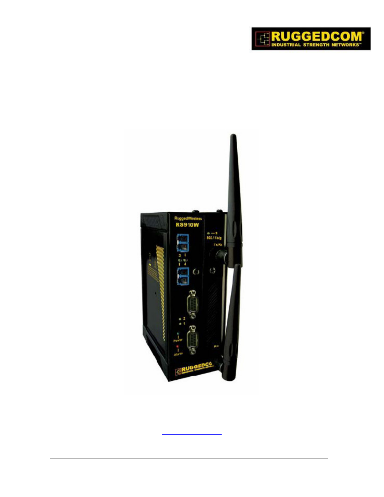
The RuggedWireless™ RS910W is an industrially hardened Wireless Serial/Ethernet Device
Server that has been specifically designed to operate reliably in electrically harsh and climatically
demanding environments. The RS910W features a wireless LAN (WLAN) interface combined with
2 serial ports and/or 2 Fast Ethernet ports. The RS910W allows you to connect any RS-232/
422/485/fiber serial devices at up to 230 kbps and/or connect Ethernet devices for wireless access
and control via an IEEE 802.11i wireless LAN.
1.2 Feature Highlights
• Serial Device Server:
o 2 fully compliant EIA/TIA RS485/RS422/RS232/fiber serial ports (software
selectable)
o DB9, RJ45 or ST fiber connectors
o Baud rates up to 230 kbps
o Built-in optional RS485 Termination
• Ethernet Ports:
o 2 – Fast Ethernet ports (10/100BaseTX or 100 BaseFX)
o Multiple fiber connector types
5
2007 RuggedCom Inc. All rights reserved Rev100
Page 6
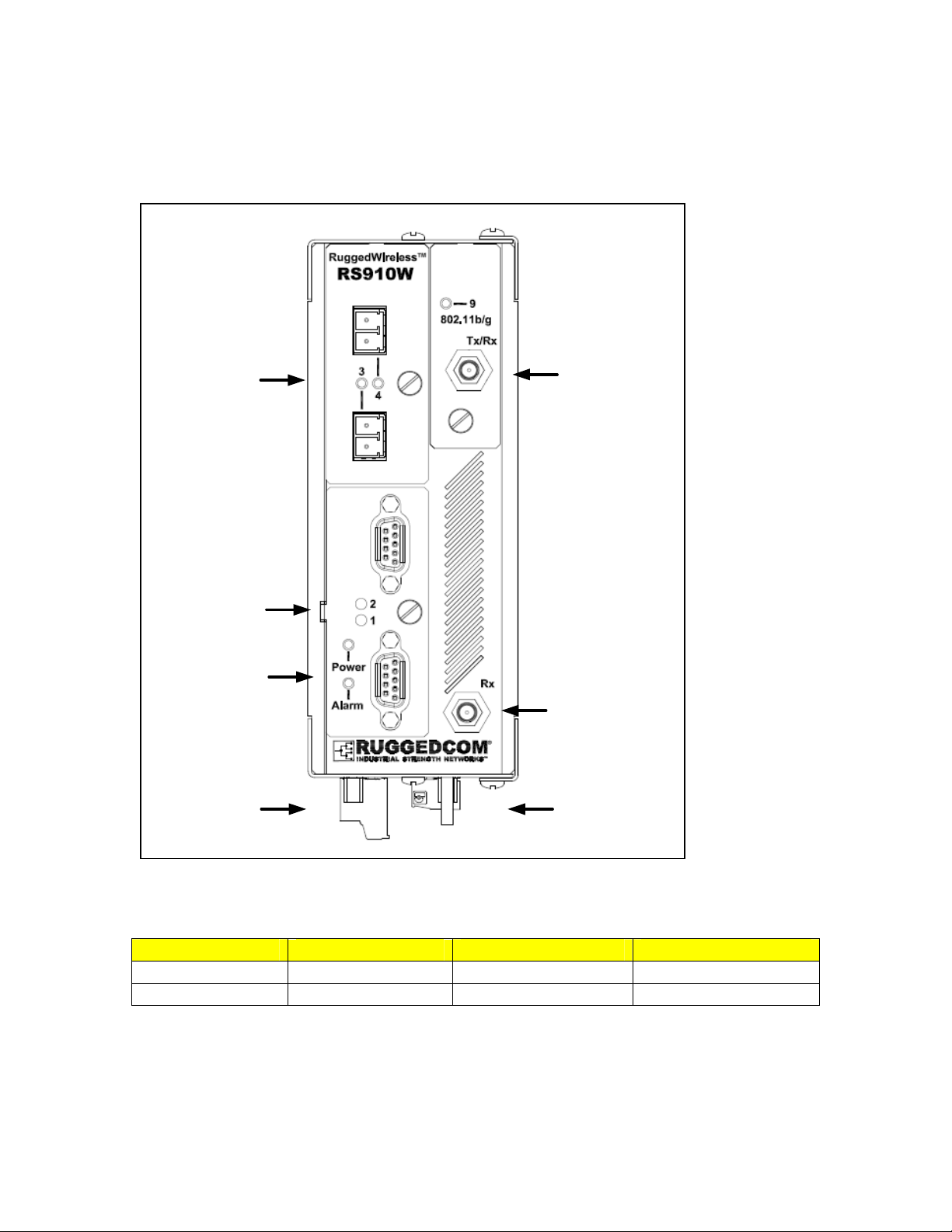
1.3 RS910W Front Panel Description
Ports 3 & 4
10/100Base-TX
or
100Base-FX
Or
10Base-FL
Ports 1 & 2
RS485/422/232
Serial
Or
Serial over Fiber
Port 9
Antenna #1
Power & Alarm
Port 9
Antenna #2
Failsafe Relay Power Port
Figure 1 - RS910W Front Panel Description
Status LED Colour Activity Comments
Power LED Green Solid Power On
Alarm LED Red Solid Alarm condition exists
Table 1 - Status LEDs
6
2007 RuggedCom Inc. All rights reserved Rev100
Page 7
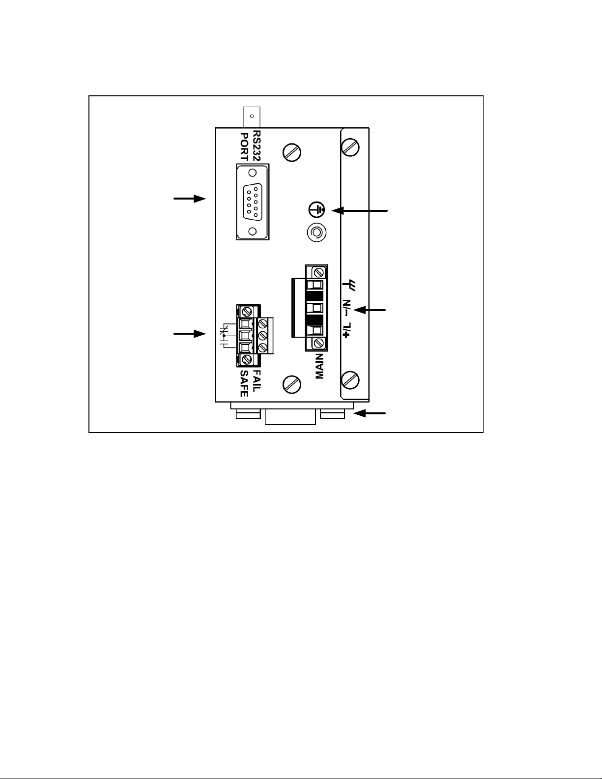
1.4 RS910W Bottom Panel Description
Console Port
Failsafe Relay
Figure 2 - RS910W Bottom Panel Description
Chassis
Ground
Power
Port
Optional Din-Rail
Mounting Bracket
7
2007 RuggedCom Inc. All rights reserved Rev100
Page 8
2 Installation
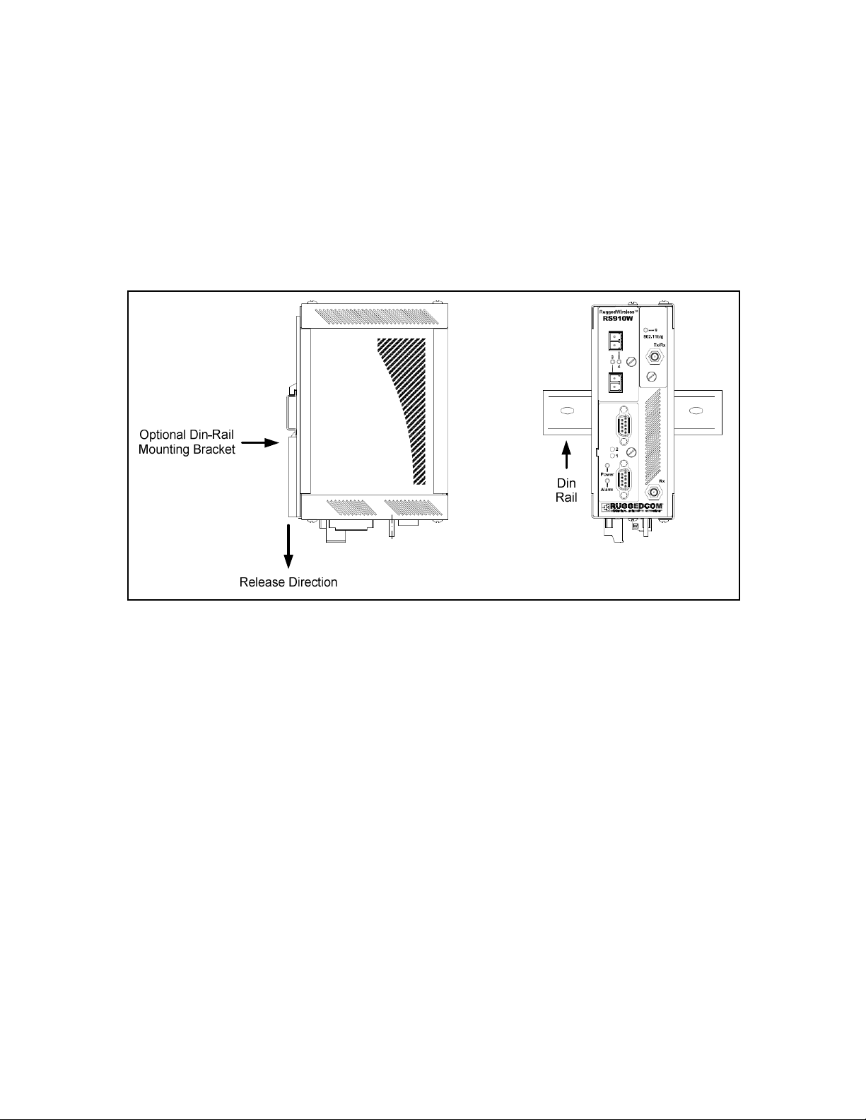
2.1 Din Rail Mounting
An optional DIN rail mounting bracket is available for the RS910W. The figure below details
mounting instructions for the standard 1” DIN Rail.
Figure 3 - RS910W DIN Rail Mounting
8
2007 RuggedCom Inc. All rights reserved Rev100
Page 9
2.2 Power Supply Wiring and Grounding
2.2.1 AC Power Supply Wiring and Grounding
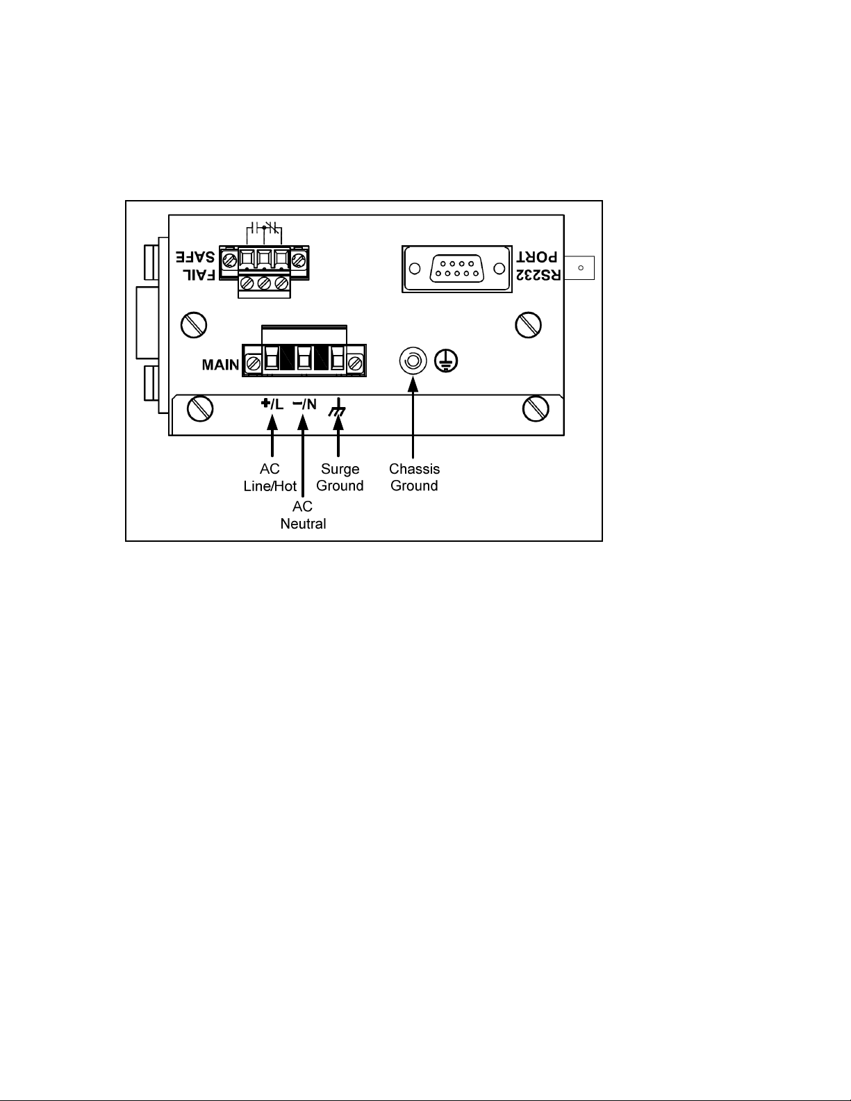
Figure 4 - RS910W Power Supply Inputs
The RS910W AC power supply inputs should be connected as follows:
1. +/L should be connected to AC Line/Hot.
2. -/N should be connected to AC Neutral.
3. Surge Ground should be connected to the Chassis Ground via a braided cable or other
appropriate grounding wire. Surge Ground is used as the ground conductor for all surge
and transient suppression circuitry internal to the unit.
4. Chassis Ground must be connected to the AC ground terminal.
NOTES:
1. Equipment must be installed according to the applicable country wiring codes.
2. All line-to-ground transient energy is shunted to the Surge Ground terminal. In cases
where users require the inputs to be isolated from ground, remove the ground braid
between Surge and Chassis Ground. Note that all line-to-ground transient protection
circuitry will be disabled.
9
2007 RuggedCom Inc. All rights reserved Rev100
Page 10
2.2.2 DC Power Supply Wiring and Grounding
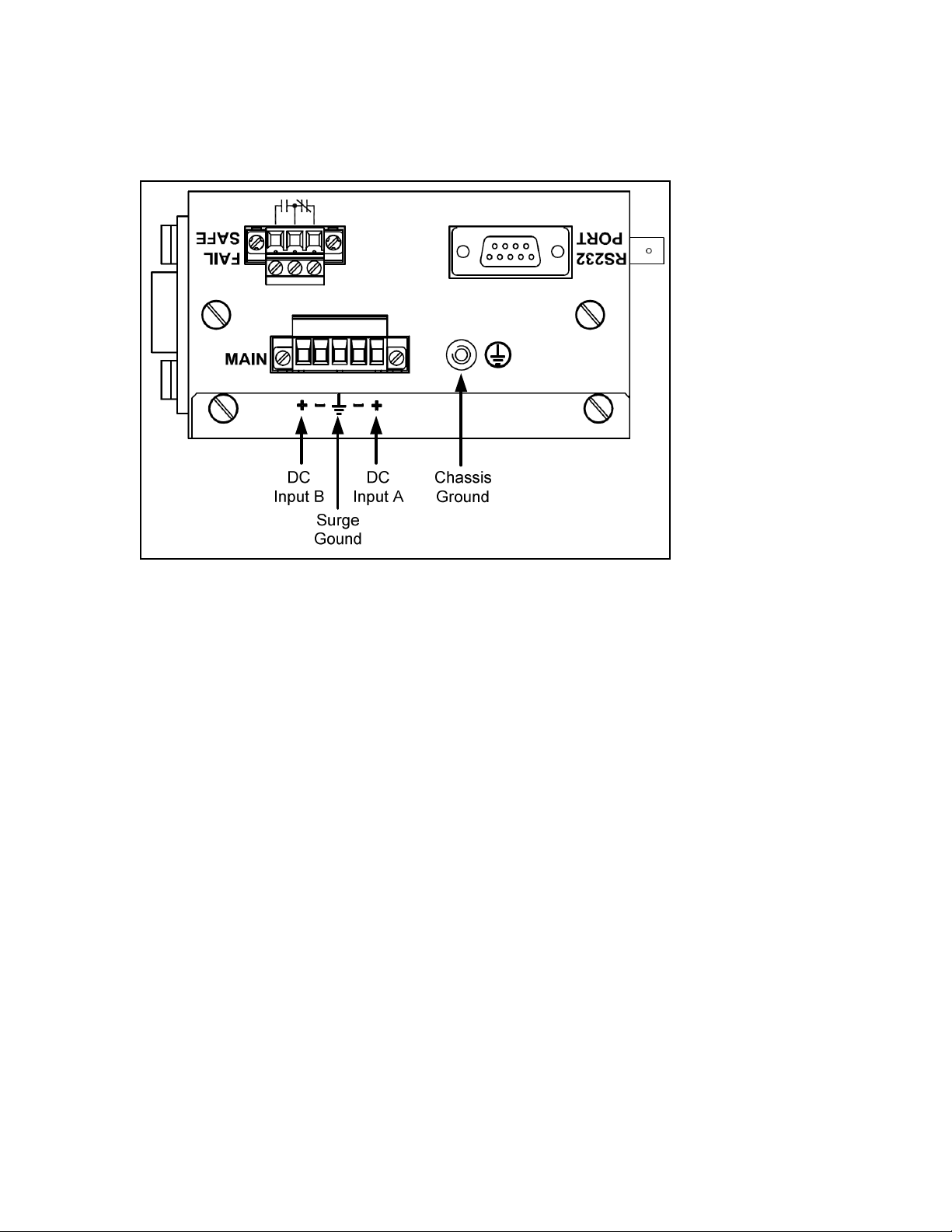
Figure 5 - DC Power supply wiring and grounding diagram
The RS910W low voltage DC power supply features reverse polarity protection and dual
independent inputs. The latter feature allows the connection of two DC sources with the same
nominal voltage to provide redundant power supply inputs.
The RS910W DC power supply inputs should be connected as follows:
1. Connect to the DC inputs according to the polarity markings on the unit.
2. Surge Ground should be connected to the Chassis Ground via a braided cable or other
appropriate grounding wire. Surge Ground is used as the ground conductor for all surge
and transient suppression circuitry internal to the unit.
3. Chassis Ground must be connected to the protective earth.
NOTES:
1. Equipment must be installed according to the applicable country wiring codes.
2. All line-to-ground transient energy is shunted to the Surge Ground terminal. In cases
where users require the inputs to be isolated from ground, remove the ground braid
between Surge and Chassis Ground. Note that all line-to-ground transient protection
circuitry will be disabled.
10
2007 RuggedCom Inc. All rights reserved Rev100
Page 11

2.2.3 Dielectric Strength Testing
Units which are to have dielectric strength testing (HIPOT testing) done in the field must have the
braided ground cable disconnected during the test. This is required in order to prevent the surge
suppression circuitry, which is connected to surge ground, from being activated.
Figure 6 - Dielectric Strength Testing
11
2007 RuggedCom Inc. All rights reserved Rev100
Page 12

2.3 Failsafe Output Wiring
The Failsafe output relay is provided to signal critical error conditions that may occur on the
RS910W. The contacts are energized upon power up of the unit and remain energized until an
alarm condition or power loss occurs. The behavior of the failsafe relay is configurable via the
RuggedSwitch Operating System. Consult the RuggedSwitch Users Guide for details.
Figure 7 - RS910W Failsafe Output Relay
12
2007 RuggedCom Inc. All rights reserved Rev100
Page 13
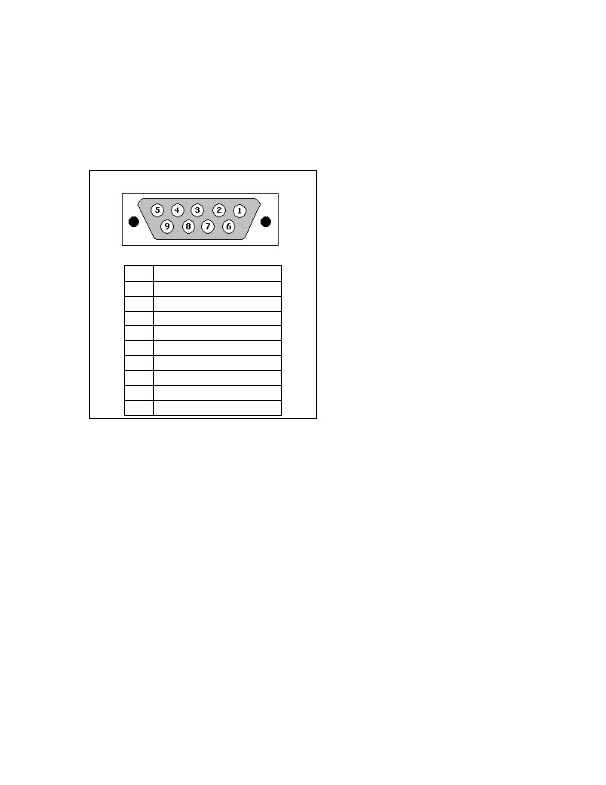
2.4 RS232 Console Port Wiring
The RS232 port is used for configuring the RS910W. A straight-through serial cable with a DB-9
connector is required. There is no need to crossover the TxD and RxD signals from the PC side
since this has been done internally as is shown in the figure below.
Pin Signal
1 Internal Connection
2 Transmit Data
3 Receive Data
4 Internal Connection
5 Ground
6 Internal Connection
7 Internal Connection
8 Internal Connection
9 No Connection
Figure 8 - RS232 Female DCE pin-out
NOTE: This port is not intended to be a permanent connection and the cable length should not
exceed 2m (6.5 feet). Pins 1,4,6 are connected internally, and pins 7, 8 are connected internally.
13
2007 RuggedCom Inc. All rights reserved Rev100
Page 14
3 Serial Ports
The RS910W can be equipped with a Fiber Serial Interface, RS232/RS485/RS422 DB9 serial ports
or RS232/RS485/RS422 RJ45 serial ports.
3.1.1 Fiber Serial Interface
The RS910W can be equipped with a Fiber Serial Interface (ST connector only) which allows
RS485, RS422, or RS232 devices to communicate over secure, noise immune, optically isolated,
fiber optic cabling at extended distances as well as protocol independent conversion to multimode
fiber optics.
Figure 9: Fiber Serial Interface (ST Connector)
3.1.2 RS232/RS485/RS422 via DB9
Each port is individually selectable via software to be RS232, RS485 or RS422. The DB9 port and
pin-out is shown in Figure 10.
14
2007 RuggedCom Inc. All rights reserved Rev100
Page 15

Pin RS232 Mode RS485 Mode RS422 Mode
1 CD - 2 TX TX/RX+ (A) TX+
3 RX - RX+
4 DTR - 5
Common (Isolated Ground)
6 DSR - RX7 CTS TX/RX - (B) TX8 RTS 9 RI (NC) - -
Shield
Figure 10: DB9 Port pin-out
Chassis Ground
NOTE: Pins 1, 4, and 6 are connected internally. Pins 7 and 8 are connected internally. No internal
termination is provided.
3.1.3 RS232/RS485/RS422 via RJ45
Each port is individually selectable via software to be RS232, RS485 or RS422. The RJ45 port and
pin-out is shown in Figure 11.
15
2007 RuggedCom Inc. All rights reserved Rev100
Page 16

Pin RS232 Mode RS485 Mode RS422 Mode
1 DSR - RX2 DCD - 3 DTR - 4
Common (Isolated Ground)
5 RX - RX+
6 TX TX/RX + (A) TX +
7 CTS - 8 RTS TX/RX - (B) TX -
Shield
Figure 11: RJ45 Port pin-out
Chassis Ground
NOTE: Pins 1, 2, and 3 are connected internally. Pins 7 and 8 are connected internally. No internal
termination is provided.
3.1.4 RS485 Wiring
Each RS485 port can communicate to multiple RS485 devices by daisy chaining devices over a
single twisted pair with transmit and receive signals on the same two wires (half duplex). The
following guidelines should be followed to ensure reliable continuous communication:
1. To minimize the effects of ambient electrical noise, shielded cabling is recommended
2. The correct polarity must be observed throughout a single daisy chain
3. The number of devices wired should not exceed 32, and total distance should be less than
4000 feet (at 100Kbps)
4. The COM terminals should be connected to the common wire inside the shield.
5. The shield should be connected to earth ground at ONE single point to avoid loop currents.
6. The twisted pair should be terminated at each end of the chain.
Figure 12 shows the recommended RS485 wiring.
16
2007 RuggedCom Inc. All rights reserved Rev100
Page 17
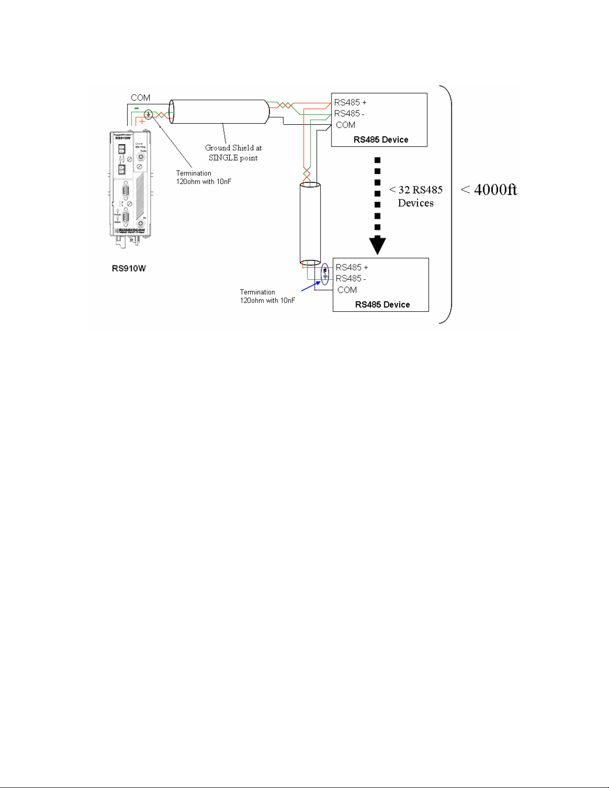
Figure 12: Conceptual recommended RS485 wiring diagram
3.1.5 Serial Port Transient Protection
RuggedCom does not recommend the use of copper cabling of any length for critical real-time
substation automation applications. However, transient suppression circuitry is present on all
copper ports to protect against damage from electrical transients and to ensure IEC 61850-3 and
IEEE 1613 Class 1 conformance. This means that during the transient event communications
errors or interruptions may occur but recovery is automatic. RuggedCom also does not recommend
to use these ports to interface to field devices across distances which could produce high levels of
ground potential rise, (i.e. greater than 2500V) during line to ground fault conditions.
17
2007 RuggedCom Inc. All rights reserved Rev100
Page 18

4 Ethernet Ports
4.1 RJ45 Ethernet Ports
The RS910W has several 10/100Base-TX ports that allow connection to standard category 5
(CAT-5) unshielded twisted-pair (UTP) cable with RJ45 male connectors. The RJ45 receptacles
are directly connected to the chassis ground on the unit and can accept CAT-5 shielded twistedpair (STP) cables. If shielded cables are used, care must be taken to ensure the shielded cables
do not form a ground loop via the shield wire and the RJ45 receptacles at either end. The figure
below shows the RJ45 port pin-out.
Figure 13 - RJ45 Ethernet port pin-out
Pin Signal
1 +Rx
2 -Rx
3 +Tx
4 No Connection
5 No Connection
6 -Tx
7 No Connection
8 No Connection
Case Shield (Chassis Ground)
Table 2 - RJ45 Ethernet port pin-out
NOTE: RuggedCom does not recommend the use of CAT-5 (10/100Base-TX communications)
cabling of any length for critical real-time substation automation applications. However, transient
suppression circuitry is present on all copper ports to protect against damage from electrical
transients and to ensure IEC 61850-3 and IEEE 1613 Class 1 conformance. This means that
during the transient event communications errors or interruptions may occur but recovery is
automatic.
18
2007 RuggedCom Inc. All rights reserved Rev100
Page 19

RuggedCom also does not recommended to use these ports to interface to field devices across
distances which could produce high levels of ground potential rise, (i.e. greater than 2500V) during
line to ground fault conditions.
4.2 Fiber Optic Ethernet Ports
Depending on the order code of the product, the RS910W can be equipped with several different
fiber optic ports. The Transmit (Tx) and Receive (Rx) connections of each port must be properly
connected and matched for proper link and operation. The drawings in the following figures show
each fiber optical connector style with a side and top view to allow the user to identify the proper
cable connection orientation.
Figure 16: 100FX ST connector
Figure 14: 10FL ST connector
Figure 15: 100FX MTRJ connector
Figure 17: 100FX LC connector
Figure 18: 100FX SC connector
4.3 Ethernet Panel Description
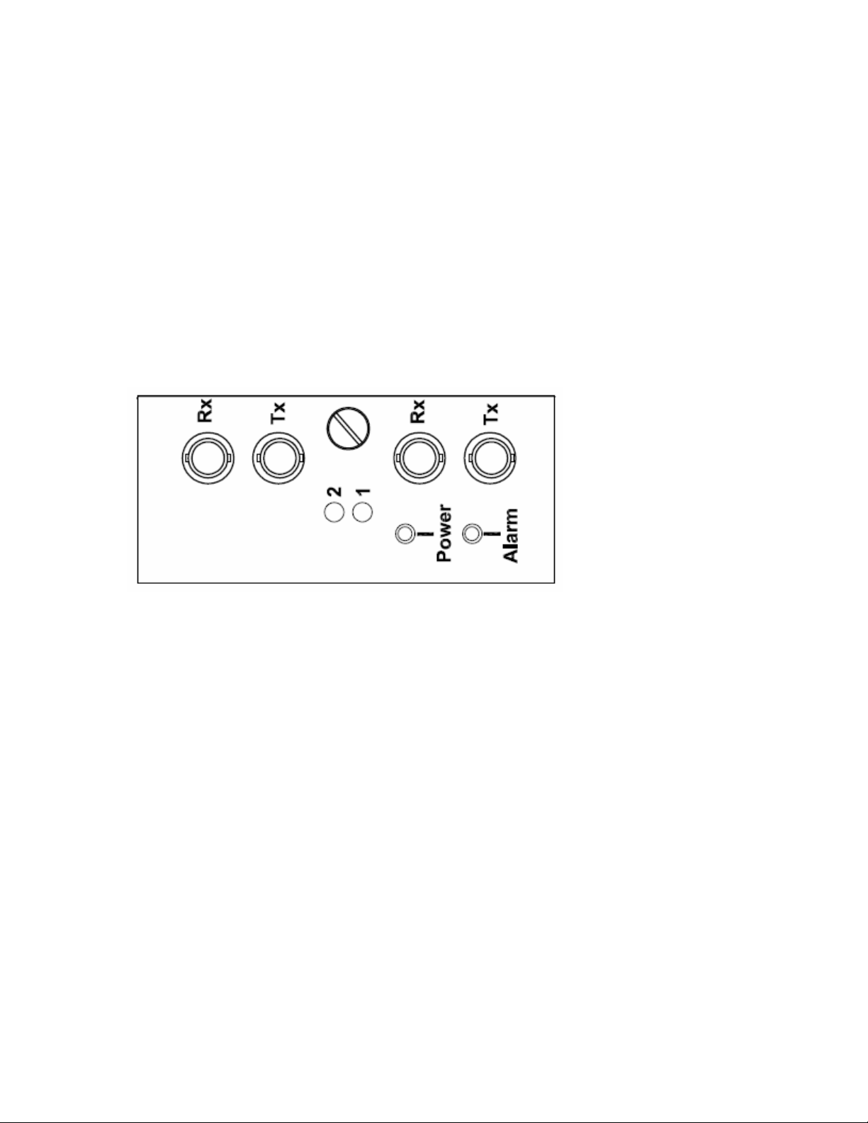
Each Ethernet and Serial port is equipped with one LED that indicates link/activity status
information. The LED will be solid for ports with link, and will blink for activity. The diagram in
Figure 19 highlights the port and the associated link/activity LED.
19
2007 RuggedCom Inc. All rights reserved Rev100
Page 20

Figure 19: Ethernet panel LED description
20
2007 RuggedCom Inc. All rights reserved Rev100
Page 21

5 Technical Specifications
5.1 Operating Environment
Parameter Range Comments
Ambient Temperature as
Ambient Operating Temperature
Ambient Storage Temperature
Ambient Relative Humidity 5% to 95% Non-condensing
Table 3 - Operating Environment
-40 to 85°C
-40 to 85°C
5.2 Power Supply Specifications
Power Supply Type
12 – 24 VDC 10 VDC 36 VDC 3.15 (T) 1.5 kV DC
24 VDC 18 VDC 36 VDC 3.15 (T) 1.5 kV DC
48 VDC 36 VDC 72 VDC 3.15 (T) 1.5 kV DC
HI (125/250 VDC) 1
HI (110/230 VAC) 1
Minimum
Input
88 VDC
85 VAC
Maximum
Input
300 VDC
265 VAC
Fuse
Rating
3.15 (T)
measured from a 30 cm radius
surrounding the center of the
RS910W enclosure.
Isolation
4 kV AC 5.5
kV DC
Maximum Power
Consumption
10W
Table 4 - Power Supply Specifications
NOTES:
1. This is the same power supply for both AC and DC.
2. (F) Denotes fast-acting fuse, (T) denotes time-delay fuse.
3. For continued protection against risk of fire, replace only with same type and rating of fuse.
5.3 Failsafe Relay Specifications
Load Circuit SELV TNV-2
MAX operating Voltage 30VDC 30 VAC 80VDC
MAX operating Current 1A 0.5A 0.3A
Isolation (between coil and contacts) 1800 V
Table 5 - Failsafe Relay Specifications
rms
21
2007 RuggedCom Inc. All rights reserved Rev100
Page 22

5.4 Wireless Standards Supported
Standard Parameter Mode Notes
IEEE 802.11g 54 Mbps (WLAN) Full Access Point 2.4 Ghz ISM
IEEE 802.11b 11 Mbps (WLAN) Client support Backwards compatibility
IEEE 802.11i Strong Encryption WPA2-AES (CCMP)
Enhanced Encryption WPA-TKIP (RC4) Temporal keys
Basic Encryption WEP (RC4) Up to 4 static keys
IEEE 802.1x Wireless Authentication ‘Personal’ or ‘Enterprise’ PSK or RADIUS
Table 6 – Wireless Standards supported
Robust Secure Network
(RSN)
5.5 Radio Characteristics
Standard Parameter
Modulation Direct Sequence Spread Spectrum 802.11b / OFDM 802.11g
Frequency Range 2.4 Ghz – 2.4965 Ghz
6-54 Mbps: OFDM
11 Mbps: CCK
Data Rate
Channels
Output Power
Receiver Sensitivity
Table 7 - Radio Characteristics
5.5 Mbps: CCK
2 Mbps: DQPSK
1 Mbps: DBPSK
11 – US (FCC)
11 - CAN (IC)
14 – Japan (MKK)
13 – Other countries (ETS)
100 mW (20dBm) 802.11b 11Mbps Data Rate
100 mW (20dBm) 802.11g 6-24Mbps Data Rate
79 mW (19dBm) 802.11g 36Mbps Data Rate
63 mW (18dBm) 802.11g 48Mbps Data Rate
40 mW (16dBm) 802.11g 54Mbps Data Rate
At Radio 802.11b 11Mb@-88dBm / With Antenna: 11Mb@-91dBm
At Radio 802.11g 54Mb@-74dBm / With Antenna: 54Mb@-77dBm
5.6 IEEE 802.11b/g
The channel identifiers, channel center frequencies, and regulatory domains of each IEEE
802.11b/g 22-MHz-wide channel are shown in the table below.
22
2007 RuggedCom Inc. All rights reserved Rev100
Page 23

Regulatory Domains
Frequency
Channel Identifier
1 2412 X X X X
2 2417 X X X X
3 2422 X X X X
4 2427 X X X X
5 2432 X X X X
6 2437 X X X X
7 2442 X X X X
8 2447 X X X X
9 2452 X X X X
10 2457 X X X X
11 2462 X X X X
12 2467 - X X X
13 2472 - X X X
14 2484 - - X -
(in MHz)
America (-A) EMEA (-E) Japan (-J)
Rest of World (-W)
Table 8 - Channel allocations for IEEE 802.11b/g
Note: Mexico is included in the Rest of World regulatory domain; however, channels 1 through 8
are for indoor use only while channels 9 through 11 can be used indoors and outdoors. Users are
responsible for ensuring that the channel set configuration is in compliance with the regulatory
standards of Mexico.
In Japan, channel 14 is not supported for 802.11g mode.
5.7 Serial Ports
5.7.1 Copper Ports
Parameter Specifications Notes
Baud Rate 300 bps – 230 kbps
Connector DB9 or RJ45
Isolation 2.5 kV
RMS 1-minute
Table 9: Copper Port Specification
23
2007 RuggedCom Inc. All rights reserved Rev100
Page 24

5.7.2 Fiber Optic Ports
Parameter Specifications
Mode Multimode
Connector ST
Typical Dist. (km) 5
Optical Wavelength (nm) 820
Cable Size
Core/Cladding (um)
Table 10: Fiber Optic Port Specification
50/125
62.5/125
NOTES:
1. Maximum segment length is greatly dependent on factors such as fiber quality, and
number of patches and splices. Please consult RuggedCom sales associates when
determining maximum segment distances.
5.8 Ethernet Ports
5.8.1 Copper Ports
Parameter Specification Notes
Speed
Duplex
Cable-Type
Wiring Standard
Max Distance
Connector
Isolation
Table 11: Ethernet Ports - Copper Specifications
5.8.2 Fiber Optic Ports
TIA/EIA T568A/B Auto-Crossover, Auto-polarity
10/100 Mbps Auto-negotiating
FDX / HDX Auto-negotiating
> Category 5 Shielded/Unshielded
100 m
RJ45
1.5 kV RMS 1-minute
24
2007 RuggedCom Inc. All rights reserved Rev100
Page 25

Speed
Standard
100Base-FX MM / ST 1310 50/125 -15.7 -33.5 -11 2 17
100Base-FX MM / SC 1310 50/125 -16/-11 -33 -11 2 17
100Base-FX MM / LC 1310 50/125 -19 / -14 -32 -14 2 15
100Base-FX MM / MTRJ 1310 50/125 -16/-11 -33.5 -11 2 17
100Base-FX SM / ST 1310 9/125 -15/-8 -32 -7 20 16.5
100Base-FX SM / SC 1310 9/125 -13/5 -31 -4 20 20
100Base-FX SM / LC 1310 9/125 -15/-8 -31 -5 15 16.5
Table 12: Ethernet Ports – Fiber Optic Specifications
Mode /
Connector
Tx
λλλλ
(nm)
Cable
Type
(
µµµµ
m)
2
Tx Pwr
(dBm peak) 3
(Min / Max)
Rx
Sensitivity
(dBm Average) 3
Rx Saturation
(dBm Peak) 3
Typical
Distance
(km) 1
Power
Budget
(dB)
NOTES:
1. Maximum segment length is dependent on factors such as fiber quality, and number of patches and splices.
Please consult RuggedCom sales associates when determining maximum segment distances.
2. To convert from average to peak add 3 dBm. To convert from peak to average, subtract 3 dBm.
5.9 Communication Standards
Protocol Standards
Ethernet IEEE 802.3
Table 13 - Communication Standard Compliance
25
2007 RuggedCom Inc. All rights reserved Rev100
Page 26

5.10 Mechanical Specifications
Parameter Value
Dimensions 16.8 x 11.7 x 6.6 cm / 6.6 x 4.6 x 2.6 inches
Weight 1.2 kg / 2.7 lbs
Enclosure 20 AWG Galvanized Steel
Table 14 - Mechanical Specifications
Figure 20 - Mechanical Specifications
26
2007 RuggedCom Inc. All rights reserved Rev100
Page 27

6 Type Tests
6.1 IEC 61850-3 Type Tests
Test Description Test Levels
IEC 61000-4-2 ESD
IEC 61000-4-3 Radiated RFI Enclosure ports 20 V/m x
IEC 61000-4-4
IEC 61000-4-5 Surge
IEC 61000-4-6
IEC 61000-4-8 Magnetic Field Enclosure ports 40 A/m continuous, 1000 A/m for 1 s N/A
IEC 61000-4-29
IEC 61000-4-11
IEC 61000-4-12
IEC 61000-4-16
IEC 61000-4-17
IEC 60255-5
IEC 60255-5 H.V. Impulse
Burst (Fast
Transient)
Induced
(Conducted) RFI
Voltage Dips &
Interrupts
Damped
Oscillatory
Mains Frequency
Voltage
Ripple on D.C.
Power Supply
Dielectric
Strength
Enclosure Contact +/- 8kV 4
Enclosure Air +/- 15kV 4
Signal ports +/- 4kV @ 2.5kHz x
D.C. Power ports +/- 4kV 4
A.C. Power ports +/- 4kV 4
Earth ground ports +/- 4kV 4
Signal ports
D.C. Power ports
A.C. Power ports
Signal ports 10V 3
D.C Power ports 10V 3
A.C. Power ports 10V 3
Earth ground ports 10V 3
D.C. Power ports
A.C. Power ports
Signal ports
D.C. Power ports
A.C. Power ports
Signal ports 30V Continuous, 300V for 1s 4
D.C. Power ports 30V Continuous, 300V for 1s 4
D.C. Power ports 10% 3
Signal ports 2kVac (Fail-Safe Relay output) N/A
D.C. Power ports 2kVac N/A
A.C. Power ports 2kVac N/A
Signal ports 5kV (Fail-Safe Relay output) N/A
D.C. Power ports 5kV N/A
A.C. Power ports 5kV N/A
+/- 4kV line-to-earth, +/- 2kV line-to-
line
+/- 2kV line-to-earth, +/- 1kV line-to-
line
+/- 4kV line-to-earth, +/- 2kV line-to-
line
30% for 0.1s, 60% for 0.1s, 100% for
0.05s
30% for 1 period, 60% for 50 periods N/A
100% for 5 periods, 100% for 50
periods2
2.5kV common, 1kV differential mode
@ 1MHz
2.5kV common, 1kV differential mode
@ 1MHz
2.5kV common, 1kV differential mode
@ 1MHz
Severity
Levels
N/A
N/A
4
3
4
3
3
3
Table 15 - IEC 61850-3 Type Tests
27
2007 RuggedCom Inc. All rights reserved Rev100
Page 28

6.2 IEEE 1613 Type Tests
Test Description Test Levels
IEEE C37.90.3 ESD
IEEE C37.90.2 Radiated RFI Enclosure ports 35 V/m
IEEE C37.90.1 Fast Transient
IEEE C37.90.1 Oscillatory
IEEE C37.90 H.V. Impulse
IEEE C37.90
Table 16 - IEEE 1613 Type Tests
NOTE:
• If the unit contains copper ports the IEEE 1613 conformance is Class 1 (During disturbance errors may occur
but recovery is automatic).
• If the unit contains all fiber ports the IEEE 1613 conformance is Class 2 (During disturbance no errors will
occur).
Dielectric
Strength
Enclosure Contact +/- 8kV
Enclosure Air +/- 15kV
Signal ports +/- 4kV @ 2.5kHz
D.C. Power ports +/- 4kV
A.C. Power ports +/- 4kV
Earth ground ports +/- 4kV
Signal ports 2.5kV common mode @ 1MHz
D.C. Power ports 2.5kV common & differential mode @ 1MHz
A.C. Power ports 2.5kV common & differential mode @ 1MHz
Signal ports 5 kV (Failsafe Relay)
D.C. Power ports 5 kV
A.C. Power ports 5 kV
Signal ports 2kVac (Failsafe Relay)
D.C. Power ports 2kVac
A.C. Power ports 2kVac
6.3 IEC Environmental Type Tests
Test Description Test Levels
IEC 60068-2-1 Cold Temperature Test Ad -40 deg. C, 16 Hours N/A
IEC 60068-2-2 Dry Heat Test Bd +85 deg. C, 16 Hours N/A
IEC 60068-2-30
IEC 60255-21-1 Vibration Tests Fc 2g @ (10-150) Hz Class 2
IEC 60255-21-2 Shock Tests Ea 30g @ 11ms Class 2
Table 17 - Environmental Type Tests
Humidity (Damp Heat,
Cyclic)
Test Db 95% (non-condensing), 55 deg C, 6 cycles N/A
28
Severity
Levels
2007 RuggedCom Inc. All rights reserved Rev100
Page 29

7 Warranty
RuggedCom warrants this product for a period of five (5) years from date of purchase. For warranty
details, visit http://www.ruggedcom.com or contact your customer service representative. Should
this product require warranty or service contact the factory at:
RuggedCom Inc.
30 Whitmore Road,
Woodbridge, Ontario
Canada L4L 7Z4
Phone: (905) 856-5288
Fax: (905) 856-1995
29
2007 RuggedCom Inc. All rights reserved Rev100
Page 30

8 Appendix A - RuggedWireless ™ Frequently Asked
Questions (FAQ)
What factors can affect wireless coverage/range?
Range estimates are typical and require line of sight. Basically that means you will need a clear
unobstructed view of the antenna from the remote point in the link. Keep in mind that walls and
obstacles will limit your operating range and could even prevent you from establishing a link.
Signals in the 2.4 Ghz generally will not penetrate metal or concrete walls. Trees and leaves are
also obstructions to 802.11 frequencies so they can partially (or even entirely) block the signal.
Other factors that will reduce range and affect coverage area include metal studs in walls, concrete
fiberboard walls, aluminum siding, foil-backed insulation in the walls or under the siding, pipes and
electrical wiring, furniture and sources of interference. Other sources of interference include the
microwave oven, other wireless equipment, cordless phones, radio transmitters and other electrical
equipment. Due to the increased gain, installing range extender antennas in the presence of
interference could actually yield either no improvement or worse range.
Which WiFi (802.11) Antenna type should I choose? Patch/Directional Antennas
Choose a patch if you want the signal more focused than from an omni-directional antenna . Patch
antennas typically transmit the signal with approximately a 30 degree beam width. This is ideal for
use in office locations, ie placed at one end of room to provide coverage for it's entire length. They
can also be used outdoors to provide short distance point to point links.
When would I choose a Parabolic Grid Antenna?
These antennas have a very narrow beamwidth and are ideal for point-to-point bridge links. Grid
antennas are highly directional and they should only be chosen to aim at one small (i.e.
concentrated) spot.
When would I choose an Omni-Directional Antenna?
Choose an Omni-directional antenna to provide a signal over a full 360 degree radius.
How many clients can associate with an access point?
An Access Point is a shared medium and acts as a wireless hub. The performance of each user
decreases as the number of users increases on an individual AP. Ideally, not more than 24 clients
should associate with the AP because the throughput of the AP is reduced with each client that
associates to the AP.
How do I convert between power expressed in ‘milliwatt’ and power expressed in ‘dBm’
units?
The formula used to convert stated ‘power’ levels to decibels (dBm – milliwatt @ 50 or 600 ohm
impedance) is given as: dBm = 10 * Log (Power in mW / 1 mW)
Conversely, the formula used to convert stated ‘power’ levels to milliwatts when expressed in dBm
is given as: Power (mW) = anti-log (dBm / 10)
30
2007 RuggedCom Inc. All rights reserved Rev100
Page 31

dBm
Watts dBm
Watts dBm Watts
0 1.0 mW 16 40 mW 32 1.6 W
1 1.3 mW 17 50 mW 33 2.0 W
2 1.6 mW 18 63 mW 34 2.5 W
3 2.0 mW 19 79 mW 35 3.2 W
4 2.5 mW 20 100 mW 36 4.0 W
5 3.2 mW 21 126 mW 37 5.0 W
6 4 mW 22 158 mW 38 6.3 W
7 5 mW 23 200 mW 39 8.0 W
8 6 mW 24 250 mW 40 10 W
9 8 mW 25 316 mW 41 13 W
10 10 mW 26 398 mW 42 16 W
11 13 mW 27 500 mW 43 20 W
12 16 mW 28 630 mW 44 25 W
13 20 mW 29 800 mW 45 32 W
14 25 mW 30 1.0 W 46 40 W
15 32 mW 31 1.3 W 47 50 W
Table 18 - dBm to Watt Conversion Table
31
2007 RuggedCom Inc. All rights reserved Rev100
 Loading...