

Page 1
Rugged
RuggedVDSL
RuggedRugged
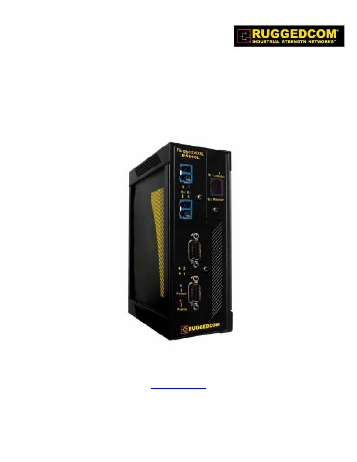
Serial and Ethernet Device Server with Ethernet over VDSL
VDSL RS9
VDSLVDSL
Uplink
RS911110000LLLL
RS9RS9
Installation Guide
www.ruggedcom.com
RuggedCom Inc. I 30 Whitmore Road, Woodbridge, Ontario, Canada L4L 7Z4
Tel: (905) 856-5288 I Fax: (905) 856-1995 I Toll Free: (888) 264-0006
Page 2

Federal Communications Commission
Radio Frequency Interference Statement
This equipment has been tested and found to comply with the limits for a Class A digital device
pursuant to Part 15 of the FCC Rules. These limits are designed to provide reasonable protection
against harmful interference when the equipment is operated in a commercial environment. This
equipment generates, uses and can radiate radio frequency energy and, if not installed and used in
accordance with the instruction manual, may cause harmful interference to radio communications.
Operation of this equipment in a residential area is likely to cause harmful interference in which
case the user will be required to correct the interference at his expense.
Caution
This product contains a laser system and is classified as a “CLASS 1 LASER PRODUCT”.
Use of controls or adjustments or performance of procedures other than those specified herein
may result in hazardous radiation exposure. This product contains no user serviceable parts.
Attempted service by unauthorized personnel shall render all warranties null and void.
Should this device require service see the “Warranty” section of this installation guide.
Important
This unit should be installed in a restricted access location where access can only be gained by
service personnel or users who have been instructed about the reasons for the restrictions
applied to the location and about any precautions that shall be taken; and access is through the
use of a tool or lock and key, or other means of security, and is controlled by the authority
responsible for the location.
Trademarks:
Ethernet is a trademark of Xerox Corporation
RuggedSwitch, RuggedRated, ROS and eRSTP are trademarks of RuggedCom® Inc.
2
2007 RuggedCom Inc. All rights reserved Rev100
Page 3

Table of Contents
1 Product Overview ............................................................................................................................... 5
1.1 Functional Overview ................................................................................................................... 5
1.2 Feature Highlights ...................................................................................................................... 5
1.3 RS910L Front Panel Description ................................................................................................ 6
1.4 RS910L Bottom Panel Description .............................................................................................. 7
2 Installation........................................................................................................................................... 8
2.1 Din Rail Mounting....................................................................................................................... 8
2.2 Power Supply Wiring and Grounding ......................................................................................... 9
2.3 Failsafe Output Wiring.............................................................................................................. 12
2.4 RS232 Console Port Wiring ...................................................................................................... 13
3 Serial Ports ........................................................................................................................................ 14
4 Ethernet Ports ................................................................................................................................... 18
4.1 RJ11 Ethernet over VDSL Port ................................................................................................. 18
4.2 RJ45 Ethernet Ports .................................................................................................................. 20
4.3 Fiber Optic Ethernet Ports ........................................................................................................ 21
4.4 Ethernet Panel Description ....................................................................................................... 22
5 Technical Specifications ................................................................................................................... 23
5.1 Operating Environment ............................................................................................................. 23
5.2 Power Supply Specifications ..................................................................................................... 23
5.3 Failsafe Relay Specifications .................................................................................................... 23
5.4 RJ11 Ethernet over VDSL Port Specifications .......................................................................... 24
5.5 Serial Ports................................................................................................................................ 24
5.6 Ethernet Ports............................................................................................................................ 25
5.7 Communication Standards ........................................................................................................ 25
5.8 Mechanical Specifications......................................................................................................... 26
6 Type Tests.......................................................................................................................................... 27
6.1 IEC 61850-3 Type Tests ............................................................................................................ 27
6.2 IEEE 1613 Type Tests ............................................................................................................... 28
6.3 IEC Environmental Type Tests .................................................................................................. 28
7 Warranty ........................................................................................................................................... 29
3
2007 RuggedCom Inc. All rights reserved Rev100
Page 4

Table of Figures
Figure 1 - RS910L Front Panel Description ............................................................................................... 6
Figure 2 - RS910L Bottom Panel Description ............................................................................................ 7
Figure 3 - RS910L DIN Rail Mounting....................................................................................................... 8
Figure 4 - RS910L Power Supply Inputs .................................................................................................... 9
Figure 5 - DC Power supply wiring and grounding diagram ................................................................. 10
Figure 6 - Dielectric Strength Testing....................................................................................................... 11
Figure 7 - RS910L Failsafe Output Relay ................................................................................................ 12
Figure 8 - RS232 Female DCE pin-out ..................................................................................................... 13
Figure 9: Fiber Serial Interface (ST Connector) ..................................................................................... 14
Figure 10: DB9 Port pin-out ...................................................................................................................... 15
Figure 11: RJ45 Port pin-out..................................................................................................................... 16
Figure 12: Conceptual recommended RS485 wiring diagram ............................................................... 17
Figure 13 - RJ11 port pin-out and LEDs.................................................................................................. 18
Figure 14 - RJ45 Ethernet port pin-out.................................................................................................... 20
Figure 15: 10FL ST connector.................................................................................................................. 21
Figure 16: 100FX MTRJ connector ......................................................................................................... 21
Figure 17: 100FX ST connector ............................................................................................................... 21
Figure 18: 100FX LC connector ............................................................................................................... 22
Figure 19: 100FX SC connector ............................................................................................................... 22
Figure 20: Ethernet panel LED description ............................................................................................ 22
Figure 21 - Mechanical Specifications ...................................................................................................... 26
Table of Tables
Table 1 - Status LEDs................................................................................................................................... 6
Table 2 - RJ11 port pin-out ....................................................................................................................... 18
Table 3 - RJ11 port LED description........................................................................................................ 18
Table 4 - Typical Performance on 24 AWG PIC twisted-pair................................................................ 19
Table 5 - RJ45 Ethernet port pin-out ....................................................................................................... 21
Table 6 - Operating Environment ............................................................................................................. 23
Table 7 - Power Supply Specifications...................................................................................................... 23
Table 8 - Failsafe Relay Specifications...................................................................................................... 23
Table 9 – RJ1 Ethernet over VDSL Port Specifications ......................................................................... 24
Table 10: Copper Port Specification......................................................................................................... 24
Table 11: Fiber Optic Port Specification.................................................................................................. 24
Table 12: Ethernet Ports - Copper Specifications ................................................................................... 25
Table 13: Ethernet Ports – Fiber Optic Specifications........................................................................... 25
Table 14 - Communication Standard Compliance .................................................................................. 25
Table 15 - Mechanical Specifications........................................................................................................ 26
Table 16 - IEC 61850-3 Type Tests ........................................................................................................... 27
Table 17 - IEEE 1613 Type Tests .............................................................................................................. 28
Table 18 - Environmental Type Tests ....................................................................................................... 28
4
2007 RuggedCom Inc. All rights reserved Rev100
Page 5

1 Product Overview
1.1 Functional Overview
The RuggedVDSLTM RS910L is an industrial hardened serial server and managed Ethernet switch
supporting Ethernet over VDSL (EoVDSL). The RS910L can be configured with 2 serial ports
(RS485/RS422/RS232/fiber) and/or 2 Ethernet ports (copper or fiber). The RS910L can
interconnect multiple types of intelligent electronic devices (IEDs) that have different methods of
communications. The EoVDSL port allows for aggregation of these devices at a remote location
back to the central control room using existing telephone grade cable (or other legacy serial
cabling). The EoVDSL uplink allows up to 4km LAN segments at up to 50 Mbps.
1.2 Feature Highlights
• Interface Ports
o 1 Ethernet over VDSL (EoVDSL) interface
o 2 Serial and/or 2 Fast Ethernet Ports
o RS485/RS422/RS232 Serial Ports (DB9 and RJ45)
o Serial Fiber Interface (ST) available
o 10/100BaseTX or 100BasesFX Ethernet ports
• Ethernet Over VDSL Port Characteristics:
o Up to 4 km LAN segments
o Symmetric data rates up to 50 Mbps
o Automatically selects fastest data rate based on distance and quality of cable
o Software selectable to be master or slave
o Frequency Division Multiplexing (FDM)
5
2007 RuggedCom Inc. All rights reserved Rev100
Page 6
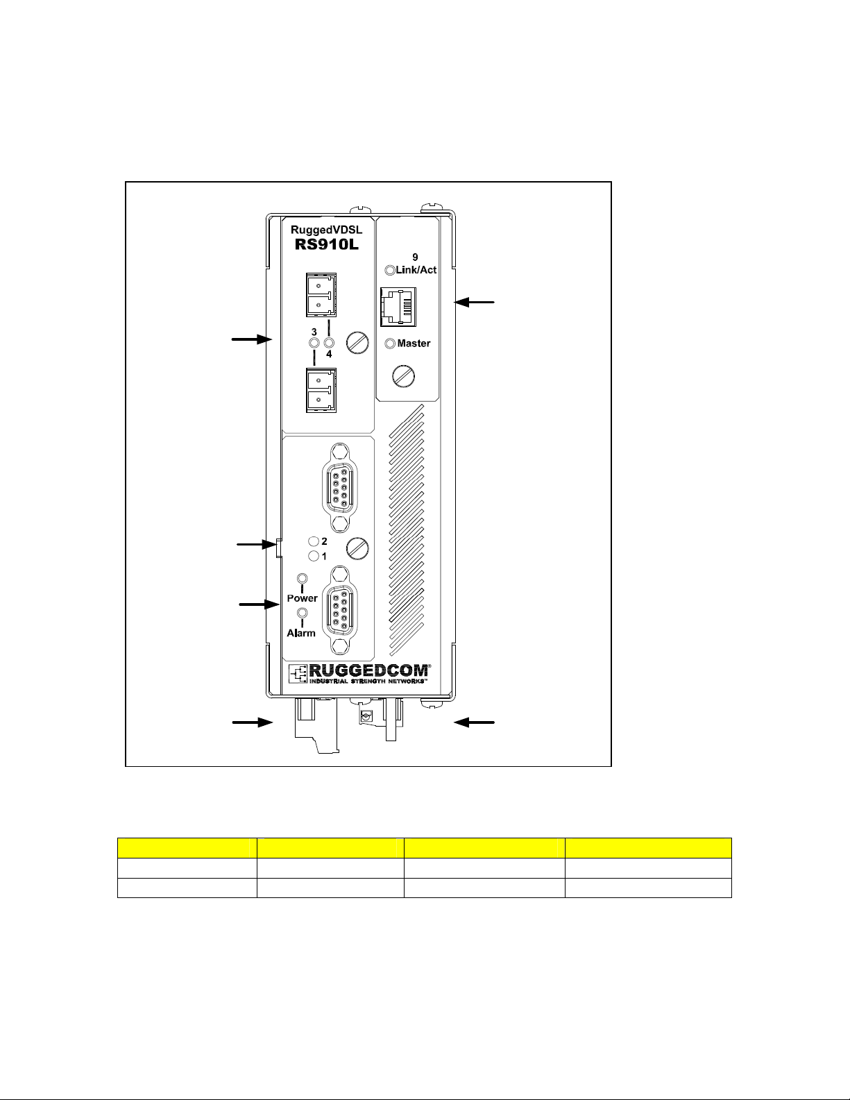
1.3 RS910L Front Panel Description
Ports 3 & 4
10/100Base-TX
or
100Base-FX
Or
10Base-FL
Ports 1 & 2
RS485/422/232
Serial
Or
Serial over Fiber
Power & Alarm
Port 9
Ethernet over VDSL
Failsafe Relay Power Port
Figure 1 - RS910L Front Panel Description
Status LED Colour Activity Comments
Power LED Green Solid Power On
Alarm LED Red Solid Alarm condition exists
Table 1 - Status LEDs
6
2007 RuggedCom Inc. All rights reserved Rev100
Page 7
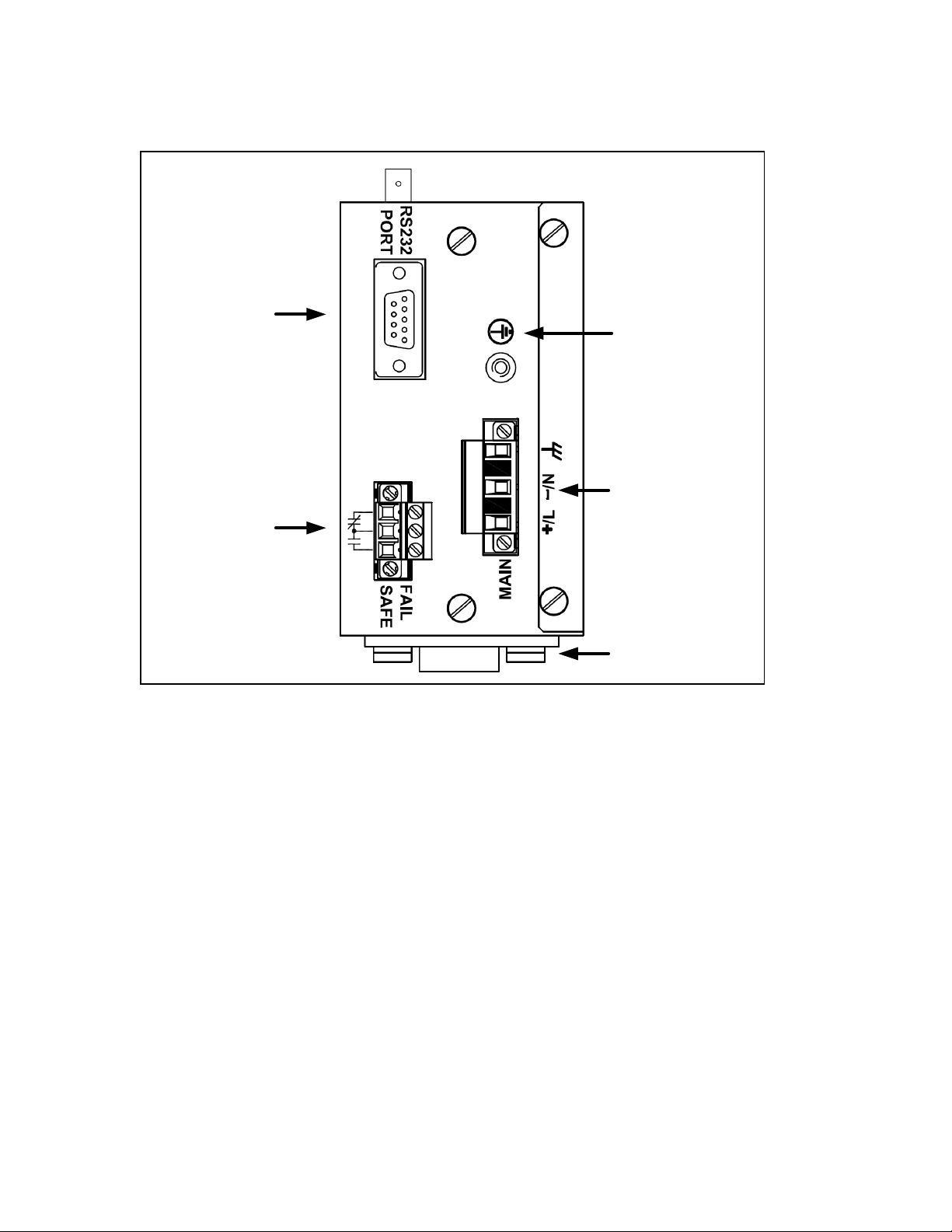
1.4 RS910L Bottom Panel Description
Console Port
Failsafe Relay
Figure 2 - RS910L Bottom Panel Description
Chassis
Ground
Power
Port
Optional Din-Rail
Mounting Bracket
7
2007 RuggedCom Inc. All rights reserved Rev100
Page 8
2 Installation
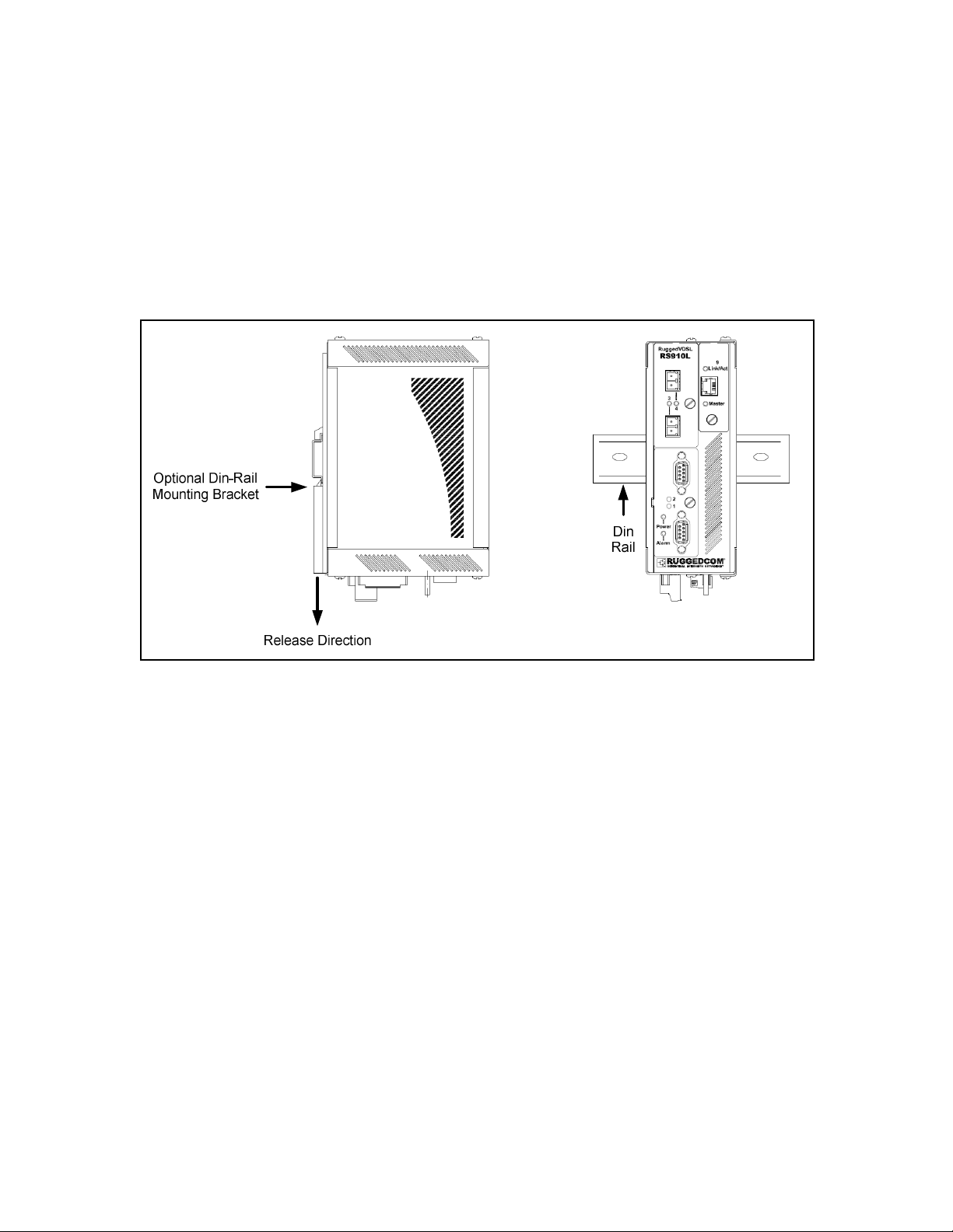
2.1 Din Rail Mounting
An optional DIN rail mounting bracket is available for the RS910L. The figure below details
mounting instructions for the standard 1” DIN Rail.
Figure 3 - RS910L DIN Rail Mounting
8
2007 RuggedCom Inc. All rights reserved Rev100
Page 9
2.2 Power Supply Wiring and Grounding
2.2.1 AC Power Supply Wiring and Grounding
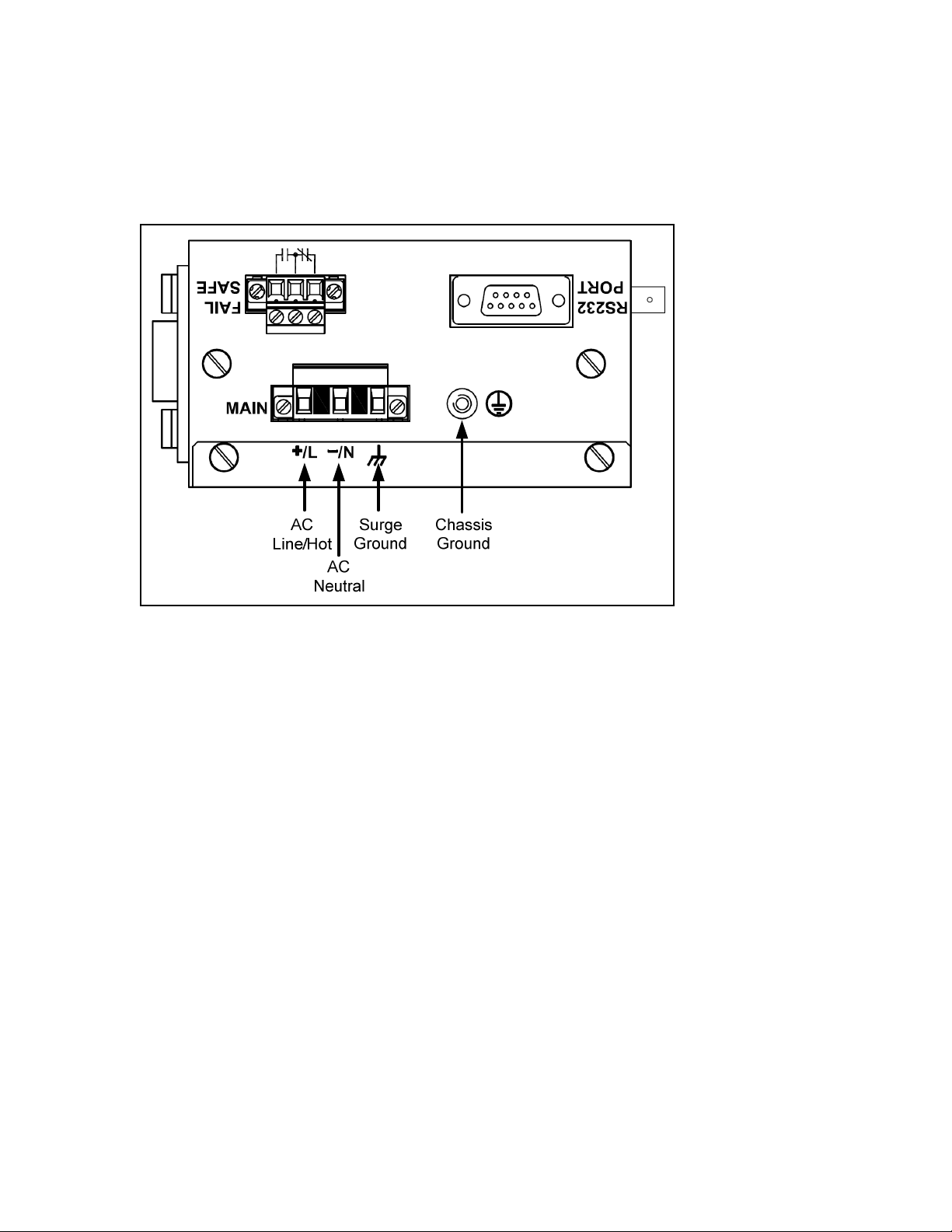
Figure 4 - RS910L Power Supply Inputs
The RS910L AC power supply inputs should be connected as follows:
1. +/L should be connected to AC Line/Hot.
2. -/N should be connected to AC Neutral.
3. Surge Ground should be connected to the Chassis Ground via a braided cable or other
appropriate grounding wire. Surge Ground is used as the ground conductor for all surge
and transient suppression circuitry internal to the unit.
4. Chassis Ground must be connected to the AC ground terminal.
NOTES:
1. Equipment must be installed according to the applicable country wiring codes.
2. All line-to-ground transient energy is shunted to the Surge Ground terminal. In cases
where users require the inputs to be isolated from ground, remove the ground braid
between Surge and Chassis Ground. Note that all line-to-ground transient protection
circuitry will be disabled.
9
2007 RuggedCom Inc. All rights reserved Rev100
Page 10
2.2.2 DC Power Supply Wiring and Grounding
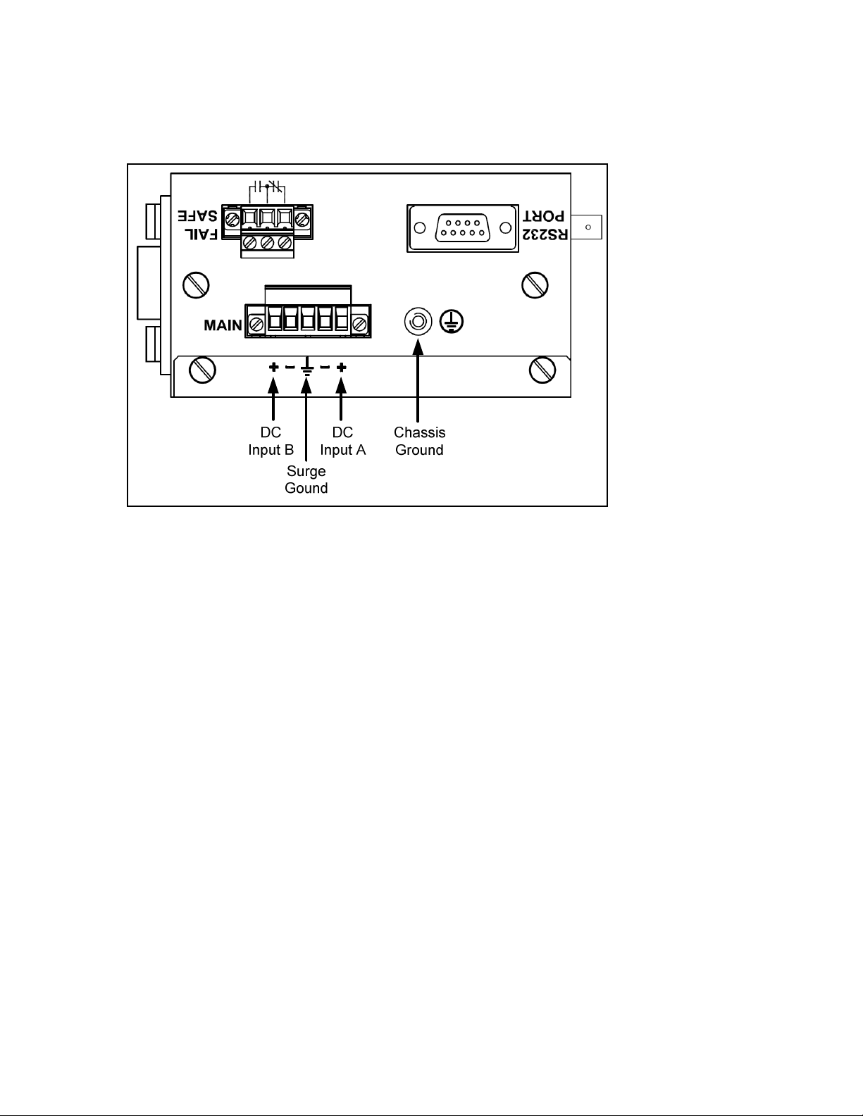
Figure 5 - DC Power supply wiring and grounding diagram
The RS910L low voltage DC power supply features reverse polarity protection and dual
independent inputs. The latter feature allows the connection of two DC sources with the same
nominal voltage to provide redundant power supply inputs.
The RS910L DC power supply inputs should be connected as follows:
1. Connect to the DC inputs according to the polarity markings on the unit.
2. Surge Ground should be connected to the Chassis Ground via a braided cable or other
appropriate grounding wire. Surge Ground is used as the ground conductor for all surge
and transient suppression circuitry internal to the unit.
3. Chassis Ground must be connected to the protective earth.
NOTES:
1. Equipment must be installed according to the applicable country wiring codes.
2. All line-to-ground transient energy is shunted to the Surge Ground terminal. In cases
where users require the inputs to be isolated from ground, remove the ground braid
between Surge and Chassis Ground. Note that all line-to-ground transient protection
circuitry will be disabled.
10
2007 RuggedCom Inc. All rights reserved Rev100
Page 11

2.2.3 Dielectric Strength Testing
Units which are to have dielectric strength testing (HIPOT testing) done in the field must have the
braided ground cable disconnected during the test. This is required in order to prevent the surge
suppression circuitry, which is connected to surge ground, from being activated.
Figure 6 - Dielectric Strength Testing
11
2007 RuggedCom Inc. All rights reserved Rev100
Page 12

2.3 Failsafe Output Wiring
The Failsafe output relay is provided to signal critical error conditions that may occur on the
RS910L. The contacts are energized upon power up of the unit and remain energized until an
alarm condition or power loss occurs. The behavior of the failsafe relay is configurable via the
RuggedSwitch Operating System. Consult the RuggedSwitch Users Guide for details.
Figure 7 - RS910L Failsafe Output Relay
12
2007 RuggedCom Inc. All rights reserved Rev100
Page 13

2.4 RS232 Console Port Wiring
The RS232 port is used for configuring the RS910L. A straight-through serial cable with a DB-9
connector is required. There is no need to crossover the TxD and RxD signals from the PC side
since this has been done internally as is shown in the figure below.
Pin Signal
1 Internal Connection
2 Transmit Data
3 Receive Data
4 Internal Connection
5 Ground
6 Internal Connection
7 Internal Connection
8 Internal Connection
9 No Connection
Figure 8 - RS232 Female DCE pin-out
NOTE: This port is not intended to be a permanent connection and the cable length should not
exceed 2m (6.5 feet). Pins 1,4,6 are connected internally, and pins 7, 8 are connected internally.
13
2007 RuggedCom Inc. All rights reserved Rev100
Page 14

3 Serial Ports
The RS910L can be equipped with a Fiber Serial Interface, RS232/RS485/RS422 DB9 serial ports
or RS232/RS485/RS422 RJ45 serial ports.
3.1.1 Fiber Serial Interface
The RS910L can be equipped with a Fiber Serial Interface (ST connector only) which allows
RS485, RS422, or RS232 devices to communicate over secure, noise immune, optically isolated,
fiber optic cabling at extended distances as well as protocol independent conversion to multimode
fiber optics.
Figure 9: Fiber Serial Interface (ST Connector)
3.1.2 RS232/RS485/RS422 via DB9
Each port is individually selectable via software to be RS232, RS485 or RS422. The DB9 port and
pin-out is shown in Figure 10.
14
2007 RuggedCom Inc. All rights reserved Rev100
Page 15

Pin RS232 Mode RS485 Mode RS422 Mode
1 CD - 2 TX TX/RX+ (A) TX+
3 RX - RX+
4 DTR - 5
Common (Isolated Ground)
6 DSR - RX7 CTS TX/RX - (B) TX8 RTS 9 RI (NC) - -
Shield
Figure 10: DB9 Port pin-out
Chassis Ground
NOTE: Pins 1, 4, and 6 are connected internally. Pins 7 and 8 are connected internally. No internal
termination is provided.
3.1.3 RS232/RS485/RS422 via RJ45
Each port is individually selectable via software to be RS232, RS485 or RS422. The RJ45 port and
pin-out is shown in Figure 11.
15
2007 RuggedCom Inc. All rights reserved Rev100
Page 16

Pin RS232 Mode RS485 Mode RS422 Mode
1 DSR - RX2 DCD - 3 DTR - 4
Common (Isolated Ground)
5 RX - RX+
6 TX TX/RX + (A) TX +
7 CTS - 8 RTS TX/RX - (B) TX -
Shield
Figure 11: RJ45 Port pin-out
Chassis Ground
NOTE: Pins 1, 2, and 3 are connected internally. Pins 7 and 8 are connected internally. No internal
termination is provided.
3.1.4 RS485 Wiring
Each RS485 port can communicate to multiple RS485 devices by daisy chaining devices over a
single twisted pair with transmit and receive signals on the same two wires (half duplex). The
following guidelines should be followed to ensure reliable continuous communication:
1. To minimize the effects of ambient electrical noise, shielded cabling is recommended
2. The correct polarity must be observed throughout a single daisy chain
3. The number of devices wired should not exceed 32, and total distance should be less than
4000 feet (at 100Kbps)
4. The COM terminals should be connected to the common wire inside the shield.
5. The shield should be connected to earth ground at ONE single point to avoid loop currents.
6. The twisted pair should be terminated at each end of the chain.
Figure 12 shows the recommended RS485 wiring.
16
2007 RuggedCom Inc. All rights reserved Rev100
Page 17

Figure 12: Conceptual recommended RS485 wiring diagram
3.1.5 Serial Port Transient Protection
RuggedCom does not recommend the use of copper cabling of any length for critical real-time
substation automation applications. However, transient suppression circuitry is present on all
copper ports to protect against damage from electrical transients and to ensure IEC 61850-3 and
IEEE 1613 Class 1 conformance. This means that during the transient event communications
errors or interruptions may occur but recovery is automatic. RuggedCom also does not recommend
to use these ports to interface to field devices across distances which could produce high levels of
ground potential rise, (i.e. greater than 2500V) during line to ground fault conditions.
17
2007 RuggedCom Inc. All rights reserved Rev100
Page 18

4 Ethernet Ports
4.1 RJ11 Ethernet over VDSL Port
4.1.1 Overview
The Ethernet over VDSL (EoVDSL) port on RS910L operates in pairs with one configured as the
Master and the other as the Slave. In VDSL literature the terms Central Office (CO) or Line
Termination (LT) are used interchangeably for the Master and the terms Customer Premise
Equipment (CPE) or Network Termination (NT) are used interchangeably for the Slave.
Configuration of Master or Slave mode is done through the RuggedSwitch Operating System.
The unit contains one EoVDSL data port that allows connection to Category 3 (CAT-3) unshielded
twisted-pair (UTP) cable with RJ11 male connectors. The figure below shows the RJ45 port pin-out
and LEDs.
Figure 13 - RJ11 port pin-out and LEDs
Pin Signal
3 Ring
4 Tip
Table 2 - RJ11 port pin-out
Status LED Colour Activity Comments
Mode Green
Link / Act Green
Table 3 - RJ11 port LED description
18
On Master Mode
Off Slave Mode
Solid Link Established
Blinking Tx Activity
2007 RuggedCom Inc. All rights reserved Rev100
Page 19

4.1.2 Wiring
VDSL typically operates over 2-wire CAT-3 wiring; however, other categorized or uncategorized
twisted-pair wiring will work although the performance will vary depending on the distance and
cable characteristics. It is important that the wiring used does not have any open leads (also known
as bridged taps or drop-lines) along its length because this will impact performance by degrading
the signal.
4.1.3 Configuration & Setup
1. Log into the RuggedSwitch Operating System.
2. Highlight Ethernet Ports and press Enter.
3. Highlight Configure/View EoVDSL Parameters and press Enter. This will take you to the
EoVDSL Parameters screen. Press Enter again.
4. Highlight Mode and press Enter.
5. Either press the Up or Down arrow to select either Master or Slave. Press Enter.
6. Press Control and A together to apply the changes.
Once configured as master and slave and connected together, the units will then attempt to
achieve the maximum speed based on the line length and conditions. The unit’s link LED may flash
on and off several times before settling on a final link speed and declaring the port up. Please see
the Rugged Operating System (ROS) Software User Guide for detailed software configuration
options.
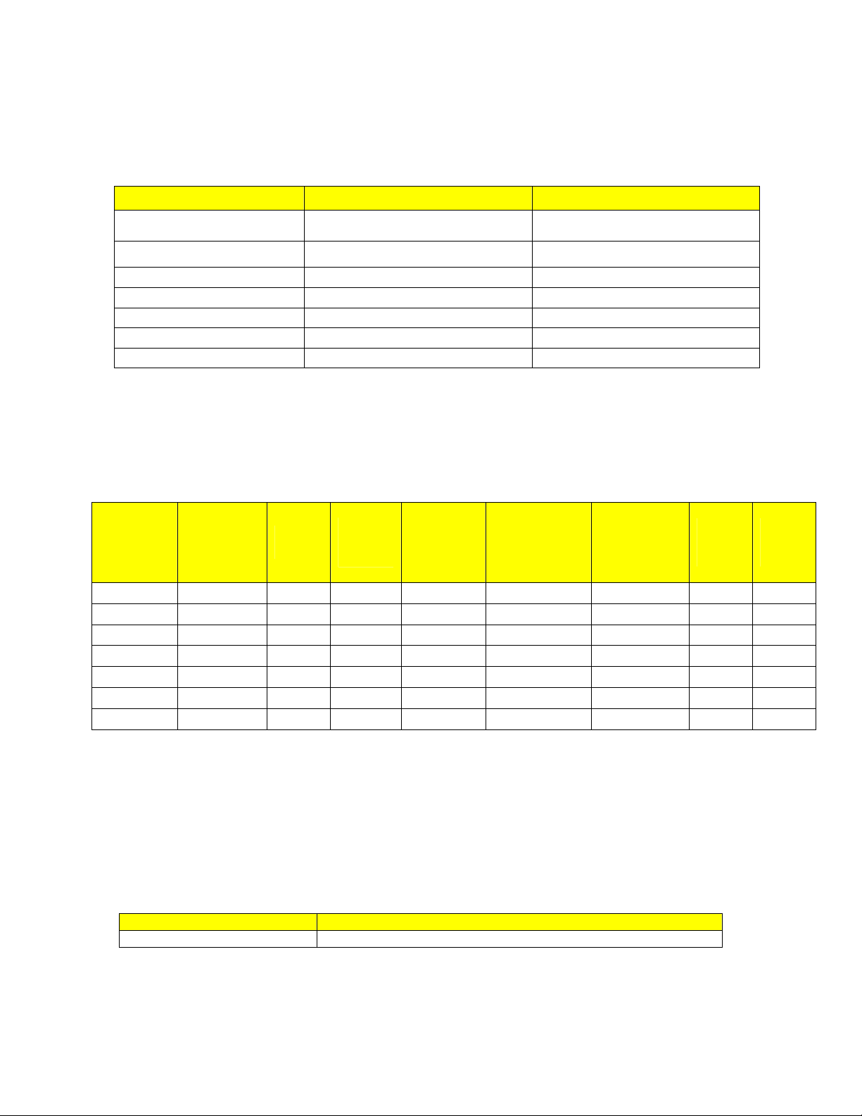
4.1.4 Performance
On 24 American Wire Gauge (AWG) Polyethylene Insulated Cable (PIC) twisted-pair the following
performance is typical:
Distance
[km]
0.5 1600 35.00 15
0.6 2000 30.00 30
0.7 2300 25.00 45
0.8 3000 20.00 60
1.0 3300 15.00 75
1.3 4300 10.00 90
1.7 5600 5.00 105
2.0 6600 2.50 120
2.5 8200 1.00 135
Table 4 - Typical Performance on 24 AWG PIC twisted-pair
Distance
[feet]
Downstream/Upstream
[Mbps]
Time to Achieve Port Up
[Seconds]
19
2007 RuggedCom Inc. All rights reserved Rev100
Page 20

The unit can automatically select the best bit-rate based on current line conditions. If the line
conditions degrade (reducing the SNR) but the unit is able to maintain the link, an alarm will be
triggered to notify the user of the reduced SNR. If the line conditions degrade such that the unit is
unable to maintain the current link, the unit will restart the scan process.
NOTES:
1. This port is designed to be used on private communications lines and is not to be connected to
the Public Switched Telephone Network (PSTN).
2. To reduce the risk of fire, use only No. 26 AWG or larger telecommunication line cord.
4.2 RJ45 Ethernet Ports
The RS910L has several 10/100Base-TX ports that allow connection to standard category 5 (CAT-
5) unshielded twisted-pair (UTP) cable with RJ45 male connectors. The RJ45 receptacles are
directly connected to the chassis ground on the unit and can accept CAT-5 shielded twisted-pair
(STP) cables. If shielded cables are used, care must be taken to ensure the shielded cables do not
form a ground loop via the shield wire and the RJ45 receptacles at either end. The figure below
shows the RJ45 port pin-out.
Figure 14 - RJ45 Ethernet port pin-out
Pin Signal
1 +Rx
2 -Rx
3 +Tx
4 No Connection
5 No Connection
6 -Tx
7 No Connection
8 No Connection
Case Shield (Chassis Ground)
20
2007 RuggedCom Inc. All rights reserved Rev100
Page 21
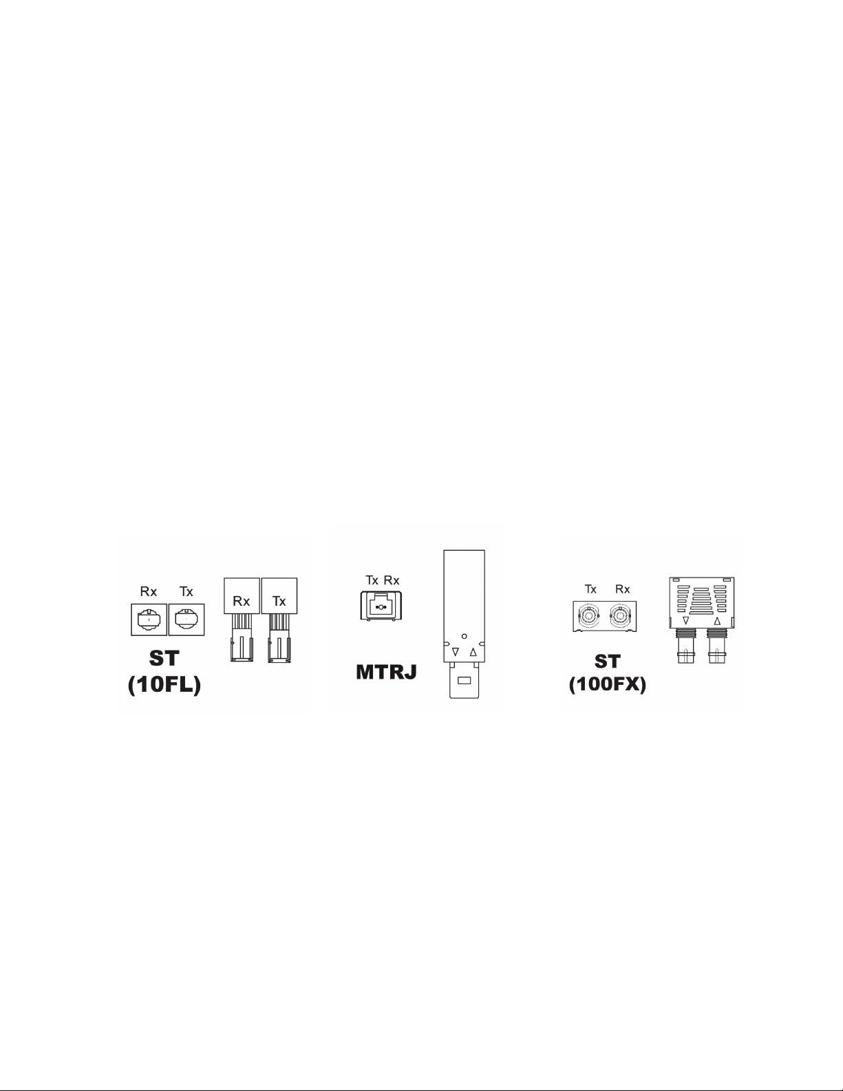
Table 5 - RJ45 Ethernet port pin-out
NOTE: RuggedCom does not recommend the use of CAT-5 (10/100Base-TX communications)
cabling of any length for critical real-time substation automation applications. However, transient
suppression circuitry is present on all copper ports to protect against damage from electrical
transients and to ensure IEC 61850-3 and IEEE 1613 Class 1 conformance. This means that
during the transient event communications errors or interruptions may occur but recovery is
automatic.
RuggedCom also does not recommended to use these ports to interface to field devices across
distances which could produce high levels of ground potential rise, (i.e. greater than 2500V) during
line to ground fault conditions.
4.3 Fiber Optic Ethernet Ports
Depending on the order code of the product, the RS910L can be equipped with several different
fiber optic ports. The Transmit (Tx) and Receive (Rx) connections of each port must be properly
connected and matched for proper link and operation. The drawings in the following figures show
each fiber optical connector style with a side and top view to allow the user to identify the proper
cable connection orientation.
Figure 17: 100FX ST connector
Figure 15: 10FL ST connector
Figure 16: 100FX MTRJ connector
21
2007 RuggedCom Inc. All rights reserved Rev100
Page 22

Figure 18: 100FX LC connector
Figure 19: 100FX SC connector
4.4 Ethernet Panel Description
Each Ethernet and Serial port is equipped with one LED that indicates link/activity status
information. The LED will be solid for ports with link, and will blink for activity. The diagram in
Figure 20 highlights the port and the associated link/activity LED.
Figure 20: Ethernet panel LED description
22
2007 RuggedCom Inc. All rights reserved Rev100
Page 23

5 Technical Specifications
5.1 Operating Environment
Parameter Range Comments
Ambient Temperature as
Ambient Operating Temperature
Ambient Storage Temperature
Ambient Relative Humidity 5% to 95% Non-condensing
Table 6 - Operating Environment
-40 to 85°C
-40 to 85°C
5.2 Power Supply Specifications
Power Supply Type
12 – 24 VDC 10 VDC 36 VDC 3.15 (T) 1.5 kV DC
24 VDC 18 VDC 36 VDC 3.15 (T) 1.5 kV DC
48 VDC 36 VDC 72 VDC 3.15 (T) 1.5 kV DC
HI (125/250 VDC) 1
HI (110/230 VAC) 1
Minimum
Input
88 VDC
85 VAC
Maximum
Input
300 VDC
265 VAC
Fuse
Rating
3.15 (T)
measured from a 30 cm radius
surrounding the center of the
RS910 enclosure.
Isolation
4 kV AC 5.5
kV DC
Maximum Power
Consumption
10W
Table 7 - Power Supply Specifications
NOTES:
1. This is the same power supply for both AC and DC.
2. (F) Denotes fast-acting fuse, (T) denotes time-delay fuse.
3. For continued protection against risk of fire, replace only with same type and rating of fuse.
5.3 Failsafe Relay Specifications
Load Circuit SELV TNV-2
MAX operating Voltage 30VDC 30 VAC 80VDC
MAX operating Current 1A 0.5A 0.3A
Isolation (between coil and contacts) 1800 V
Table 8 - Failsafe Relay Specifications
rms
23
2007 RuggedCom Inc. All rights reserved Rev100
Page 24
5.4 RJ11 Ethernet over VDSL Port Specifications
Data Port Media Distance Connector Type
VDSL CAT-3 UTP or STP 2500m RJ11
Table 9 – RJ1 Ethernet over VDSL Port Specifications
5.5 Serial Ports
5.5.1 Copper Ports
Parameter Specifications Notes
Baud Rate 300 bps – 230 kbps
Connector DB9 or RJ45
Isolation 2.5 kV
Table 10: Copper Port Specification
5.5.2 Fiber Optic Ports
Parameter Specifications
Mode Multimode
Connector ST
Typical Dist. (km) 5
Optical Wavelength (nm) 820
Cable Size
Core/Cladding (um)
Table 11: Fiber Optic Port Specification
50/125
62.5/125
RMS 1-minute
NOTES:
1. Maximum segment length is greatly dependent on factors such as fiber quality, and
number of patches and splices. Please consult RuggedCom sales associates when
determining maximum segment distances.
24
2007 RuggedCom Inc. All rights reserved Rev100
Page 25
5.6 Ethernet Ports
5.6.1 Copper Ports
Parameter Specification Notes
Speed
Duplex
Cable-Type
Wiring Standard
Max Distance
Connector
Isolation
Table 12: Ethernet Ports - Copper Specifications
10/100 Mbps Auto-negotiating
FDX / HDX Auto-negotiating
> Category 5 Shielded/Unshielded
TIA/EIA T568A/B Auto-Crossover, Auto-polarity
100 m
RJ45
1.5 kV RMS 1-minute
5.6.2 Fiber Optic Ports
Speed
Standard
100Base-FX MM / ST 1310 50/125 -15.7 -33.5 -11 2 17
100Base-FX MM / SC 1310 50/125 -16/-11 -33 -11 2 17
100Base-FX MM / LC 1310 50/125 -19 / -14 -32 -14 2 15
100Base-FX MM / MTRJ 1310 50/125 -16/-11 -33.5 -11 2 17
100Base-FX SM / ST 1310 9/125 -15/-8 -32 -7 20 16.5
100Base-FX SM / SC 1310 9/125 -13/5 -31 -4 20 20
100Base-FX SM / LC 1310 9/125 -15/-8 -31 -5 15 16.5
Mode /
Connector
Tx
(nm)
λλλλ
Cable
Type
(
µµµµ
m)
2
Tx Pwr
(dBm peak) 3
(Min / Max)
Rx
Sensitivity
(dBm Average) 3
Rx Saturation
(dBm Peak) 3
Typical
Distance
(km) 1
Power
Budget
(dB)
Table 13: Ethernet Ports – Fiber Optic Specifications
NOTES:
1. Maximum segment length is dependent on factors such as fiber quality, and number of patches and splices.
Please consult RuggedCom sales associates when determining maximum segment distances.
2. To convert from average to peak add 3 dBm. To convert from peak to average, subtract 3 dBm.
5.7 Communication Standards
Protocol Standards
Ethernet IEEE 802.3
Table 14 - Communication Standard Compliance
25
2007 RuggedCom Inc. All rights reserved Rev100
Page 26

5.8 Mechanical Specifications
Parameter Value
Dimensions 16.8 x 11.7 x 6.6 cm / 6.6 x 4.6 x 2.6 inches
Weight 1.2 kg / 2.7 lbs
Enclosure 20 AWG Galvanized Steel
Table 15 - Mechanical Specifications
Figure 21 - Mechanical Specifications
26
2007 RuggedCom Inc. All rights reserved Rev100
Page 27

6 Type Tests
6.1 IEC 61850-3 Type Tests
Test Description Test Levels
IEC 61000-4-2 ESD
IEC 61000-4-3 Radiated RFI Enclosure ports 20 V/m x
IEC 61000-4-4
IEC 61000-4-5 Surge
IEC 61000-4-6
IEC 61000-4-8 Magnetic Field Enclosure ports 40 A/m continuous, 1000 A/m for 1 s N/A
IEC 61000-4-29
IEC 61000-4-11
IEC 61000-4-12
IEC 61000-4-16
IEC 61000-4-17
IEC 60255-5
IEC 60255-5 H.V. Impulse
Burst (Fast
Transient)
Induced
(Conducted) RFI
Voltage Dips &
Interrupts
Damped
Oscillatory
Mains Frequency
Voltage
Ripple on D.C.
Power Supply
Dielectric
Strength
Enclosure Contact +/- 8kV 4
Enclosure Air +/- 15kV 4
Signal ports +/- 4kV @ 2.5kHz x
D.C. Power ports +/- 4kV 4
A.C. Power ports +/- 4kV 4
Earth ground ports +/- 4kV 4
Signal ports
D.C. Power ports
A.C. Power ports
Signal ports 10V 3
D.C Power ports 10V 3
A.C. Power ports 10V 3
Earth ground ports 10V 3
D.C. Power ports
A.C. Power ports
Signal ports
D.C. Power ports
A.C. Power ports
Signal ports 30V Continuous, 300V for 1s 4
D.C. Power ports 30V Continuous, 300V for 1s 4
D.C. Power ports 10% 3
Signal ports 2kVac (Fail-Safe Relay output) N/A
D.C. Power ports 2kVac N/A
A.C. Power ports 2kVac N/A
Signal ports 5kV (Fail-Safe Relay output) N/A
D.C. Power ports 5kV N/A
A.C. Power ports 5kV N/A
+/- 4kV line-to-earth, +/- 2kV line-to-
line
+/- 2kV line-to-earth, +/- 1kV line-to-
line
+/- 4kV line-to-earth, +/- 2kV line-to-
line
30% for 0.1s, 60% for 0.1s, 100% for
0.05s
30% for 1 period, 60% for 50 periods N/A
100% for 5 periods, 100% for 50
periods2
2.5kV common, 1kV differential mode
@ 1MHz
2.5kV common, 1kV differential mode
@ 1MHz
2.5kV common, 1kV differential mode
@ 1MHz
Severity
Levels
N/A
N/A
4
3
4
3
3
3
Table 16 - IEC 61850-3 Type Tests
27
2007 RuggedCom Inc. All rights reserved Rev100
Page 28

6.2 IEEE 1613 Type Tests
Test Description Test Levels
IEEE C37.90.3 ESD
IEEE C37.90.2 Radiated RFI Enclosure ports 35 V/m
IEEE C37.90.1 Fast Transient
IEEE C37.90.1 Oscillatory
IEEE C37.90 H.V. Impulse
IEEE C37.90
Table 17 - IEEE 1613 Type Tests
NOTE:
• If the unit contains copper ports the IEEE 1613 conformance is Class 1 (During disturbance errors may occur
but recovery is automatic).
• If the unit contains all fiber ports the IEEE 1613 conformance is Class 2 (During disturbance no errors will
occur).
Dielectric
Strength
Enclosure Contact +/- 8kV
Enclosure Air +/- 15kV
Signal ports +/- 4kV @ 2.5kHz
D.C. Power ports +/- 4kV
A.C. Power ports +/- 4kV
Earth ground ports +/- 4kV
Signal ports 2.5kV common mode @ 1MHz
D.C. Power ports 2.5kV common & differential mode @ 1MHz
A.C. Power ports 2.5kV common & differential mode @ 1MHz
Signal ports 5 kV (Failsafe Relay)
D.C. Power ports 5 kV
A.C. Power ports 5 kV
Signal ports 2kVac (Failsafe Relay)
D.C. Power ports 2kVac
A.C. Power ports 2kVac
6.3 IEC Environmental Type Tests
Test Description Test Levels
IEC 60068-2-1 Cold Temperature Test Ad -40 deg. C, 16 Hours N/A
IEC 60068-2-2 Dry Heat Test Bd +85 deg. C, 16 Hours N/A
IEC 60068-2-30
IEC 60255-21-1 Vibration Tests Fc 2g @ (10-150) Hz Class 2
IEC 60255-21-2 Shock Tests Ea 30g @ 11ms Class 2
Table 18 - Environmental Type Tests
Humidity (Damp Heat,
Cyclic)
Test Db 95% (non-condensing), 55 deg C, 6 cycles N/A
28
Severity
Levels
2007 RuggedCom Inc. All rights reserved Rev100
Page 29

7 Warranty
RuggedCom warrants this product for a period of five (5) years from date of purchase. For warranty
details, visit http://www.ruggedcom.com or contact your customer service representative. Should
this product require warranty or service contact the factory at:
RuggedCom Inc.
30 Whitmore Road,
Woodbridge, Ontario
Canada L4L 7Z4
Phone: (905) 856-5288
Fax: (905) 856-1995
29
2007 RuggedCom Inc. All rights reserved Rev100
 Loading...