

Page 1
RuggedSwitch
RuggedSwitch
RuggedSwitchRuggedSwitch
RS500
RS500
RS500 RS500
Installation Guide
Installation Guide
Installation GuideInstallation Guide
RuggedCom Inc.
30 Whitmore Road,
Woodbridge, Ontario
Canada L4L 7Z4
Web: www.ruggedcom.com
Tel: (905) 856-5288
Fax: (905) 856-1995
Toll Free: (888) 264-0006
Page 2

Federal Communications Commission Radio Frequency Interference
Statement
This equipment has been tested and found to comply with the limits for a Class A digital device
pursuant to Part 15 of the FCC Rules. These limits are designed to provide reasonable protection
against harmful interference when the equipment is operated in a commercial environment. This
equipment generates, uses and cad radiate radio frequency energy and, if not installed and used in
accordance with the instruction manual, may cause harmful interference to radio communications.
Operation of this equipment in a residential area is likely to cause harmful interference in which
case the user will be required to correct the interference on his own expense.
Warning: Changes or modifications not expressly approved by RuggedCom Inc. could void the
user’s authority to operate the equipment.
Trademarks:
Ethernet is a trademark of Xerox Corporation
RuggedSwitch is a registered trademark of RuggedCom Inc.
Important:
The RS500 contains no user serviceable parts. Attempted service by unauthorized personnel shall
render all warranties null and void.
The RS500 should be installed in a restricted access location where access can only be gained
by service personnel or users who have been instructed about the reasons for the restrictions
applied to the location and about any precautions that shall be taken; and access is through the
use of a tool or lock and key, or other means of security, and is controlled by the authority
responsible for the location.
2
2008 RuggedCom Inc. All rights reserved Rev101
Page 3

Table of Contents
1 Product Overview.....................................................................................................................4
1.1 Functional Overview............................................................................................... 4
1.2 Feature Highlights.................................................................................................. 4
1.3 RS500 Front Panel Description ............................................................................... 5
1.4 RS500 Top and Bottom View .................................................................................. 6
2 Installation................................................................................................................................7
2.1 DIN Rail Mounting.................................................................................................. 7
2.2 Power Supply Wiring and Grounding ....................................................................... 8
2.2.1 Power Supply - DC Input.................................................................................... 9
2.3 HIPOT (Dielectric Strength) Testing ....................................................................... 10
2.4 Failsafe Output Wiring and Specifications............................................................... 11
3 Technical Specifications.........................................................................................................12
3.1 Power Supply Specifications ................................................................................. 12
3.2 Failsafe Relay Specifications................................................................................. 12
3.3 Networking Standards Supported .......................................................................... 12
3.4 Fiber Optical Specifications................................................................................... 13
3.5 Networking Performance Specifications ................................................................. 13
3.6 Type Test Specifications....................................................................................... 14
3.7 Operating Environment......................................................................................... 15
3.8 Physical Dimensions ............................................................................................ 15
3.9 Agency Approvals ................................................................................................ 16
4 Warranty.................................................................................................................................16
3
2008 RuggedCom Inc. All rights reserved Rev101
Page 4

1 Product Overview
1.1 Functional Overview
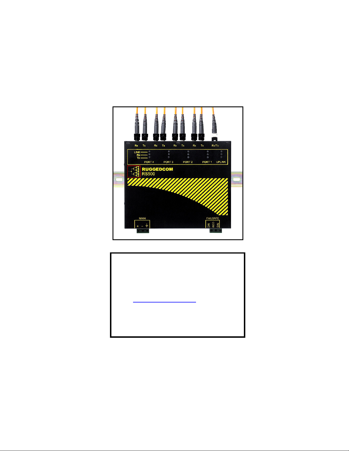
The RuggedSwitch RS500 is a substation hardened, fiber optical Ethernet switch specifically
designed to operate in harsh environments such as those found in electric utility substations and
harsh industrial environments. The RS500 provides 4 10BaseFL fiber optical ports and one
100BaseFX port.
Specifically tested to the same standards as mission critical protective relaying equipment (i.e.
ANSI/IEEE C37.90 and IEC 60255) the RS500 is ideally suited to form the Ethernet network in a
UCA2 (Utility Communications Architecture 2.0) based substation automation network. Because
the RS500 was designed to meet the demands of the substation environment it is also ideally
suited for industrial automation networks based on Industrial Ethernet. The reliability of the RS500
exceeds that of commercial Ethernet switches by having no rotating mechanical parts such as
cooling fans and by utilizing high-temperature solid-state components.
1.2 Feature Highlights
Utility Grade (i.e. substation hardened) per ANSI/IEEE C37.90, IEC 60255, and the new IEC
61850-3 (2002), IEC 61000-6-5 standards
Operating temperature: -40° to 85°C (no fan)
Radiated RF Immunity: 35V/m per ANSI/IEEE C37.90.2
Power supply options: 24VDC, 48VDC or 110VDC
Failsafe output relay for critical failure or error alarming
4 – 10BaseFL (10Mbps) multimode
1 – 100BaseFX fiber optical port
Full-duplex operation (no collisions)
4
2008 RuggedCom Inc. All rights reserved Rev101
Page 5
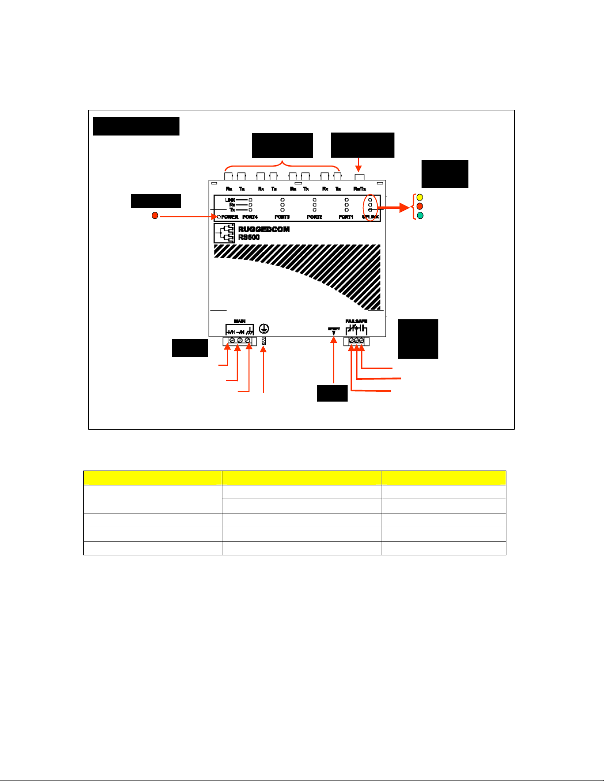
1.3 RS500 Front Panel Description
Front Panel View
10BaseFL Ports
ST Connectors
POWER LED
Power
DC(+)
DC(-)
Surge Ground
Safety Ground
Stud
100BaseFX Port
MTRJ Connector
Reset
LED
Indicators
LINK/Activity
Rx (Receive)
Tx (Transmit)
Failsafe
Output
Relay
Normally Open
Common
Normally Closed
Fig. 1.3.1 RS500 Front Panel Detail
ITEM Activity Comments
Solid Link Established LINK LED (Yellow)
Blinking – Once per second Tx, Rx Activity
Tx LED (Red) Blinking Tx (Transmit) Activity
Rx LED (Green) Blinking Rx (Receive) Activity
POWER LED (Red) Solid Power On
5
2008 RuggedCom Inc. All rights reserved Rev101
Page 6

1.4 RS500 Top and Bottom View
Top View
Bottom View
DC(+)
DC(-)
Surge Ground
DIN Rail Mounting
10BaseFL Ports
ST Connectors
Safety Ground
Stud
DIN Rail Mounting
Bracket
100BaseFX Port
MTRJ Connector
Reset
Failsafe Output
Relay
Bracket
Fig. 1.4.1 RS500 Top and Bottom View
6
2008 RuggedCom Inc. All rights reserved Rev101
Page 7

2 Installation
2.1 DIN Rail Mounting
RS500 DIN Rail
Mounting & Release
Side View
DIN RAIL
DIN RAIL
Mounting Latch
Release Slot
Release
Direction
Screw Driver
Fig. 2.1.1 RS500 Rail Mounting
Front View
DIN RAIL
Release Action
7
2008 RuggedCom Inc. All rights reserved Rev101
Page 8

2.2 Power Supply Wiring and Grounding
Safety Ground
Stud
DC(+)
DC(-)
Surge Ground
Fig. 2.2.1 RS500 Power Supply Inputs
The power supply input is connected as follows:
1. + = DC (+) is connected to the positive (+) terminal if the power source is DC or to the
(Hot) terminal if the power source is AC.
2. - = DC (-) is connected to the negative (-) terminal if the power source is DC or to the
(Neutral) terminal if the power source is AC.
3.
Surge Ground
circuitry internal to the RS500. Surge Ground is connected directly to the safety ground
terminal internally.
NOTE: Since the Chassis Ground is connected to the equipment ground bus internally, HIPOT
testing cannot be performed in the field.
is used as the ground conductor for all surge and transient suppression
8
2008 RuggedCom Inc. All rights reserved Rev101
Page 9

2.2.1 Power Supply - DC Input
Fig. 2.2.2 Power Supply – DC Input
Note: Ground bus can either be connected to the Ground Stud on the rear of the RS500 chassis,
or the Surge Ground port on the screw-in terminal block.
9
2008 RuggedCom Inc. All rights reserved Rev101
Page 10

2.3 HIPOT (Dielectric Strength) Testing
HIPOT Dielectric strength testing
suppression circuitry connected to the RS500 Surge/Chassis Ground. All RuggedSwitch products
are HIPOT tested according to IEC 60255-5 (Section 6) during final test.
cannot
be performed in the field due to transient/surge
10
2008 RuggedCom Inc. All rights reserved Rev101
Page 11

2.4 Failsafe Output Wiring and Specifications
The “Failsafe” output relay is provided to signal critical error conditions that may occur on the
RS500. The contacts are energized upon power up of the unit and remain energized until a critical
error occurs.
RS500 Failsafe Relay Outputs
Normally Closed Common Normally Open
*** Normal contact state prior to power being applied to unit. ***
11
2008 RuggedCom Inc. All rights reserved Rev101
Page 12

3 Technical Specifications
3.1 Power Supply Specifications
Power Supply Type Minimum
Input
24 VDC 18 VDC 36 VDC 5A(F)
48 VDC 36 VDC 59 VDC 3.15A(T)
HI (110 VDC) 88 VDC 150 VDC 3.15A(T)
NOTES:
1. (T) denotes time-delay fuse
2. For continued protection against risk of fire, replace only with same type and rating of fuse.
3.2 Failsafe Relay Specifications
Parameter Value (Resistive)
Maximum
Input
Fuse Rating Maximum Power
Consumption
10 W
Max Switching Voltage 30VAC, 80VDC
Rated Switching Current 0.3A @ 30VAC
1A @ 30VDC, 0.3A @ 80VDC
3.3 Networking Standards Supported
Parameter 10Mbps Ports 100Mbps Ports
IEEE 802.3
IEEE 802.3u
IEEE 802.3x
Notes
10BaseT / 10BaseFL
100BaseTX / 100BaseFX
Full Duplex Operation
12
2008 RuggedCom Inc. All rights reserved Rev101
Page 13

3.4 Fiber Optical Specifications
Parameter
Multi-Mode Single-Mode* Multi-Mode Single-Mode*
Speed Standard 10BaseFL 100BaseFX
Connector Type ST MTRJ LC
Segment Length 2 km 15 km 2 km 15 km
Optical Wavelength 820nm 1310nm 1300nm 1310nm
Cable Size
Core/Cladding
Optical Tx Power
Min/Max (dBm Peak)
Optical Rx Sensitivity
(dBm Average)
Max Optical Rx Power
(dBm Peak)
Typical Optical
Power Budget (dB)
* Available as an option
62.5/125µm 9/125µm 62.5/125µm 9/125µm
-13.5/-7.6 -23/-15 -16/-11 -15/-8
Ports 1 to 4
10Mbps Ports
-34.4 -38 -33.5 -31
-8.2 -3.0 -11 -5
22 18 17 16.5
Uplink
100Mbps Port
3.5 Networking Performance Specifications
Parameter 10Mbps Ports
(10BaseFL)
Latency 16us + frame time 5us + frame time
Filtering Rate 14 880 148 800 Frames/sec
MAC Address Table 8192
VLAN Address Table 4096
100Mbps Ports
(100BaseFX)
Notes
13
2008 RuggedCom Inc. All rights reserved Rev101
Page 14

3.6 Type Test Specifications
Electrical Safety Levels Comments
Dielectric Withstand 2 kV rms for 1 minute ANSI/IEEE C37.90 (1989)
IEC 60255-5 (Section 6)
High Voltage Impulse 5 kV peak IEC 60255-5 (Section 8)
Insulation Resistance 500 VDC for 1 minute IEC 60255-5 (Section 6
Electrical Environment Levels Comments
High Frequency Disturbance
(Oscillatory)
IEC Surge 4 kV / 2 kV IEC 61000-4-5
IEC Fast Transient 2 kV / 1 kV IEC 61000-4-4
ANSI/IEEE Fast Transient 4 kV ANSI/IEEE C37.90.1
IEC Radiated RFI Immunity 10 V/m IEC 61000-4-3
ANSI/IEEE Radiated RFI
Immunity
ESD
(Electrostatic Discharge)
Atmospheric Environment Levels Comments
Temperature (Dry Cold)
Temperature (Dry Heat)
Humidity 95%
2.5 kV @ 1MHz for 2s ANSI/IEEE C37.90.1
IEC 60255-22-1
(Level 4)
(Level 4)
35 V/m
15 kV (air discharge)
8 kV (contact)
-40°C
85°C
Non-condensing
Test Ad: 16 hrs @ -40°C
Test Db: 6 cycles, 55°C, 95%
ANSI/IEEE C37.90.2
IEC 61000-4-2
(Level 4)
IEC 60068-2-1
IEC 60068-2-2
Test Bd: 16 hrs @ 85°C
IEC 60068-2-30
Humidity
14
2008 RuggedCom Inc. All rights reserved Rev101
Page 15

3.7 Operating Environment
Parameter Range Comments
Ambient Operating
Temperature
Ambient Relative Humidity 5% to 95% Non-condensing
Ambient Storage
Temperature
-40 to 85°C
-40 to 85°C
Ambient Temperature as
measured from a 30cm
radius surrounding the
center of the R500
enclosure.
3.8 Physical Dimensions
15
2008 RuggedCom Inc. All rights reserved Rev101
Page 16

Parameter Value Comments
Dimensions 8.0 x 6.84 x 2.43 inches
(203,20) x (173,74) x (61,72) mm
(Length x Width x Height)
with mounting brackets
installed
Weight 5 lb (2.25 Kg)
Enclosure 18 gauge Galvanized Steel
3.9 Agency Approvals
Agency Standards Comments
cCSAus, CE
CSA C22.2 No. 60950, UL 60950, EN 60950
EN 61000-6-2
Approved
FCC FCC Part 15, Class A Approved
4 Warranty
RuggedCom warrants this product for a period of five (5) years from date of purchase. For
warranty details, visit http://www.ruggedcom.com/ or contact your customer service representative.
Should this product require warranty or service contact the factory at:
RuggedCom Inc.
30 Whitmore Road,
Woodbridge, Ontario
Canada L4L 7Z4
Phone: (905) 856-5288
Fax: (905) 856-1995
16
2008 RuggedCom Inc. All rights reserved Rev101
 Loading...