

Page 1

Rugged Operating System
(ROS™)
v3.5 User Guide
For use with:
RS400
Release 3.5.0 - June, 2008
Page 2

Copyright
COPYRIGHT © 2008 RuggedCom Inc. ALL RIGHTS RESERVED
Dissemination or reproduction of this document, or evaluation and communication of its contents, is not
authorized except where expressly permitted. Violations are liable for damages. All rights reserved,
particularly for the purposes of patent application or trademark registration.
This document contains proprietary information, which is protected by copyright. All rights are reserved.
No part of this document may be photocopied, reproduced or translated to another language without
the prior written consent of RuggedCom Inc.
Disclaimer of liability
We have checked the contents of this manual against the hardware and software described. However,
deviations from the description cannot be completely ruled out.
RuggedCom shall not be liable for any errors or omissions contained herein or for consequential
damages in connection with the furnishing, performance, or use of this material.
The information given in this document is reviewed regularly and any necessary corrections will be
included in subsequent editions. We appreciate any suggested improvements. We reserve the right to
make technical improvements without notice.
Registered Trademarks
RuggedSwitch™ and RuggedServer™ are registered trademarks of RuggedCom Inc. Other
designations in this manual might be trademarks whose use by third parties for their own purposes
would infringe the rights of the owner.
Warranty
Five (5) years from date of purchase, return to factory. For warranty details, visit www.ruggedcom.com
or contact your customer service representative.
Contacting RuggedCom
Corporate Headquarters US Headquarters Europe Headquarters
RuggedCom Inc.
30 Whitmore Road
Woodbridge, Ontario
Canada, L4L 7Z4
Tel: (905) 856-5288
Fax: (905) 856-1995
Toll-free: 1 (888) 264-0006
RuggedCom
1930 Harrison St., Suite-307
Hollywood, Florida
USA, 33020
Tel: (954) 922-7975
Fax: (954) 922-7984
Toll-free: 1 (866) 922-7975
Email: RuggedSales@RuggedCom.com
Technical Support
Toll Free (North America): 1 (866) 922-7975
International: +1 (905) 856-5288
Email: Support@RuggedCom.com
Web: www.RuggedCom.com
RuggedCom
Unit 41, Aztec Centre,
Aztec West, Almondsbury, Bristol
United Kingdom BS32 4TD
Tel: +44 1454 203 404
Fax: +44 1454 203 403
Page 3

Table Of Contents
Table Of Contents
Table Of Contents.....................................................................................................................................3
Table Of Figures .......................................................................................................................................9
Preface ...................................................................................................................................................13
Supported Platforms ...........................................................................................................................13
Who Should Use This User Guide ......................................................................................................13
How Chapters are organized ..............................................................................................................13
Document Conventions.......................................................................................................................13
Applicable Firmware Revision.............................................................................................................14
Firmware/User Guide Version Numbering System .............................................................................14
1 Administration .................................................................................................................................15
1.1 The ROS™ User Interface.......................................................................................................15
1.1.1 Using the RS232 Port to Access the User Interface .......................................................15
1.1.2 The Structure of the User Interface .................................................................................16
1.1.3 Making Configuration Changes .......................................................................................16
1.1.4 Updates Occur In Real Time ...........................................................................................17
1.1.5 Alarm Indications Are Provided .......................................................................................17
1.1.6 The CLI Shell...................................................................................................................17
1.2 The ROS™ Secure Shell Server .............................................................................................17
1.2.1 Using a Secure Shell to Access the User Interface.........................................................17
1.2.2 Using a Secure Shell to Transfer Files............................................................................17
1.3 The ROS™ Web Server Interface ...........................................................................................18
1.3.1 Using a Web Browser to Access the Web Interface........................................................18
1.3.2 The Structure of the Web Interface .................................................................................21
1.3.3 Making Configuration Changes .......................................................................................21
1.3.4 Updating Statistics Displays ............................................................................................22
1.4 Administration Menu ...............................................................................................................23
1.5 IP Interfaces ............................................................................................................................25
1.6 IP Gateways............................................................................................................................28
1.7 IP Services ..............................................................................................................................29
1.8 System Identification ...............................................................................................................31
1.9 Passwords...............................................................................................................................32
1.10 Time and Date.........................................................................................................................34
1.11 SNMP Management................................................................................................................36
1.11.1 SNMP Users....................................................................................................................36
1.11.2 SNMP Security to Group Maps .......................................................................................38
1.11.3 SNMP Access .................................................................................................................39
1.12 RADIUS...................................................................................................................................42
1.12.1 RADIUS overview............................................................................................................42
1.12.2 User Login Authentication and Authorization ..................................................................42
1.12.3 802.1X Authentication (not supported in RS400, N/A for RMC30)..................................43
1.12.4 Radius Server Configuration ...........................................................................................44
1.13 TACACS+ ...............................................................................................................................46
1.13.1 User Login Authentication and Authorization ..................................................................46
1.13.2 TACACS+ Server Configuration......................................................................................46
RS400 3 ROS™ v3.5
Page 4

Table Of Contents
1.14
DHCP Relay Agent (N/A for RMC30)......................................................................................48
1.15 Syslog .....................................................................................................................................49
1.15.1 Configuring Local Syslog.................................................................................................49
1.15.2 Configuring Remote Syslog Client ..................................................................................50
1.15.3 Configuring Remote Syslog Server .................................................................................50
1.16 Troubleshooting ......................................................................................................................52
2 Serial Protocols ...............................................................................................................................53
2.1 Serial Protocols Overview .......................................................................................................53
2.1.1 ‘Raw Socket’ protocol features........................................................................................53
2.1.2 ‘Preemptive Raw Socket’ protocol features.....................................................................53
2.1.3 ‘Modbus’ protocol features ..............................................................................................54
2.1.4 ‘DNP’ protocol features ...................................................................................................54
2.1.5 ‘Microlok’ protocol features..............................................................................................54
2.1.6 ‘WIN’ protocol features ....................................................................................................54
2.1.7 ‘TIN’ protocol features .....................................................................................................54
2.2 Serial Protocols Operation ......................................................................................................55
2.2.1 Serial Encapsulation Applications ...................................................................................55
2.2.2 Modbus Server and Client Applications ..........................................................................59
2.2.3 DNP 3.0, Microlok, TIN and WIN Applications ................................................................62
2.2.4 Transport Protocols .........................................................................................................65
2.2.5 Force Half Duplex Mode of Operation.............................................................................66
2.3 Serial Protocol Configuration and Statistics ............................................................................67
2.3.1 Serial Ports......................................................................................................................68
2.3.2 Raw Socket .....................................................................................................................70
2.3.3 Preemptive Raw Socket ..................................................................................................73
2.3.4 Modbus Server ................................................................................................................75
2.3.5 Modbus Client .................................................................................................................76
2.3.6 WIN and TIN....................................................................................................................77
2.3.7 MicroLok..........................................................................................................................79
2.3.8 DNP.................................................................................................................................80
2.3.9 Mirrored Bits ....................................................................................................................81
2.3.10 Device Addresses ...........................................................................................................83
2.3.11 Dynamic Device Addresses ............................................................................................85
2.3.12 Links Statistics.................................................................................................................86
2.3.13 Connection Statistics .......................................................................................................87
2.3.14 Serial Port Statistics ........................................................................................................88
2.3.15 Clearing Serial Port Statistics ..........................................................................................90
2.3.16 Resetting Serial Ports......................................................................................................90
2.4 Troubleshooting ......................................................................................................................91
3 Ethernet Ports .................................................................................................................................93
3.1 Controller Protection Through Link-Fault-Indication (LFI) .......................................................93
3.2 Ethernet Ports Configuration and Status.................................................................................95
3.2.1 Port Parameters ..............................................................................................................96
3.2.2 Port Rate Limiting............................................................................................................99
3.2.3 Port Mirroring.................................................................................................................100
3.2.4 Link Detection Options ..................................................................................................102
3.2.5 PoE Parameters (when applicable)...............................................................................103
3.2.6 EoVDSL Parameters (when applicable)........................................................................105
3.2.7 Port Status.....................................................................................................................108
Page 5

Table Of Contents
3.2.8
Resetting Ports..............................................................................................................109
3.3 Troubleshooting ....................................................................................................................109
4 Ethernet Statistics .........................................................................................................................111
4.1 Viewing Ethernet Statistics....................................................................................................112
4.2 Viewing Ethernet Port Statistics ............................................................................................114
4.3 Clearing Ethernet Port Statistics ...........................................................................................119
4.4 Remote Monitoring (RMON) .................................................................................................120
4.4.1 RMON History Controls.................................................................................................120
4.4.2 RMON History Samples ................................................................................................122
4.4.3 RMON Alarms ...............................................................................................................125
4.5 RMON Events .......................................................................................................................129
4.6 RMON Event Log ..................................................................................................................131
5 Spanning Tree ..............................................................................................................................133
5.1 RSTP Operation....................................................................................................................133
5.1.1 RSTP States and Roles ................................................................................................134
5.1.2 Edge Ports.....................................................................................................................136
5.1.3 Point-to-Point and Multipoint Links................................................................................136
5.1.4 Path and Port Costs ......................................................................................................136
5.1.5 Bridge Diameter ............................................................................................................137
5.2 MSTP Operation ...................................................................................................................138
5.2.1 MST Regions and Interoperability .................................................................................138
5.2.2 MSTP Bridge and Port Roles ........................................................................................139
5.2.3 Benefits of MSTP ..........................................................................................................141
5.2.4 Implementing MSTP on a Bridged Network ..................................................................142
5.3 RSTP Applications ................................................................................................................143
5.3.1 RSTP in Structured Wiring Configurations ....................................................................143
5.3.2 RSTP in Ring Backbone Configurations .......................................................................144
5.3.3 RSTP Port Redundancy ................................................................................................145
5.4 Spanning Tree Configuration ................................................................................................146
5.4.1 Bridge RSTP Parameters..............................................................................................147
5.4.2 Port RSTP Parameters..................................................................................................150
5.4.3 MST Region Identifier....................................................................................................153
5.4.4 Bridge MSTI Parameters...............................................................................................154
5.4.5 Port MSTI Parameters...................................................................................................155
5.5 Spanning Tree Statistics .......................................................................................................157
5.5.1 Bridge RSTP Statistics ..................................................................................................157
5.5.2 Port RSTP Statistics......................................................................................................159
5.5.3 Bridge MSTI Statistics ...................................................................................................162
5.5.4 Port MSTI Statistics.......................................................................................................163
5.6 Troubleshooting ....................................................................................................................166
6 VLANs ...........................................................................................................................................169
6.1 VLAN Operation ....................................................................................................................169
6.1.1 VLANs and Tags ...........................................................................................................169
6.1.2 Tagged vs. Untagged Frames.......................................................................................169
6.1.3 Native VLAN..................................................................................................................169
6.1.4 Management VLAN .......................................................................................................169
6.1.5 Edge and Trunk Port Types ..........................................................................................170
6.1.6 VLAN Ingress and Egress Rules...................................................................................170
RS400 5 ROS™ v3.5
Page 6

Table Of Contents
6.1.7
Forbidden Ports List ......................................................................................................171
6.1.8 VLAN-aware and VLAN-unaware operation modes......................................................171
6.1.9 GVRP (Generic VLAN Registration Protocol) ...............................................................172
6.1.10 QinQ (not supported in RS400 and RS8000/RS1600 families).....................................173
6.2 VLAN Applications ................................................................................................................175
6.2.1 Traffic Domain Isolation.................................................................................................175
6.2.2 Administrative Convenience..........................................................................................176
6.2.3 Reduced Hardware .......................................................................................................176
6.3 VLAN Configuration ..............................................................................................................177
6.3.1 Global VLAN Parameters ..............................................................................................177
6.3.2 Static VLANs .................................................................................................................178
6.3.3 Port VLAN Parameters..................................................................................................180
6.3.4 VLAN Summary.............................................................................................................182
6.4 Troubleshooting ....................................................................................................................183
7 Classes of Service ........................................................................................................................185
7.1 CoS Operation ......................................................................................................................185
7.1.1 Inspection Phase...........................................................................................................185
7.1.2 Forwarding Phase .........................................................................................................186
7.2 CoS Configuration.................................................................................................................187
7.2.1 Global CoS Parameters ................................................................................................187
7.2.2 Port CoS Parameters ....................................................................................................188
7.2.3 Priority to CoS Mapping ................................................................................................189
7.2.4 DSCP to CoS Mapping..................................................................................................191
7.2.5 CoS Access Priorities (RS8000 and RS1600 families only)..........................................192
8 Multicast Filtering ..........................................................................................................................195
8.1 IGMP .....................................................................................................................................195
8.1.1 Router and Host IGMP Operation .................................................................................195
8.1.2 Switch IGMP Operation.................................................................................................196
8.1.3 Combined Router and Switch IGMP Operation.............................................................198
8.2 Multicast Filtering Configuration and Status..........................................................................200
8.2.1 Configuring IGMP Parameters ......................................................................................200
8.2.2 Configuring Static Multicast Groups ..............................................................................202
8.2.3 Viewing IP Multicast Groups .........................................................................................203
8.3 Troubleshooting ....................................................................................................................204
9 MAC Address Tables ....................................................................................................................207
9.1 Viewing MAC Addresses.......................................................................................................208
9.2 Configuring MAC Address Learning Options ........................................................................209
9.3 Configuring Static MAC Address Table.................................................................................209
9.4 Purging MAC Address Table.................................................................................................211
10 Network Discovery ....................................................................................................................213
10.1 LLDP Operation ....................................................................................................................213
10.2 Network Discovery Menu ......................................................................................................214
10.2.1 Global LLDP Parameters ..............................................................................................215
10.2.2 Port LLDP Parameters ..................................................................................................216
10.2.3 LLDP Global Remote Statistics.....................................................................................217
10.2.4 LLDP Neighbor Information...........................................................................................218
10.2.5 LLDP Statistics ..............................................................................................................219
Page 7

Table Of Contents
11
PPP over Modem ......................................................................................................................221
11.1 PPP over Modem Operation .................................................................................................221
11.1.1 Remote Dial-in For Monitoring ......................................................................................221
11.1.2 Router Concentration ....................................................................................................222
11.1.3 Assigning IP Addresses For PPP ..................................................................................223
11.1.4 PAP/CHAP Authentication ............................................................................................223
11.1.5 Static Routes .................................................................................................................224
11.2 PPP Configuration.................................................................................................................225
11.2.1 Modem Settings ............................................................................................................226
11.2.2 PPP Control...................................................................................................................227
11.2.3 PPP Users .....................................................................................................................229
11.2.4 PPP Statistics ................................................................................................................231
11.2.5 Clearing PPP Statistics .................................................................................................233
11.2.6 Resetting PPP ...............................................................................................................233
11.3 Troubleshooting ....................................................................................................................234
12 Diagnostics................................................................................................................................237
12.1 Using the Alarm System........................................................................................................237
12.1.1 Active Alarms ................................................................................................................238
12.1.2 Passive Alarms..............................................................................................................238
12.1.3 Alarms and the Critical Failure Relay ............................................................................238
12.1.4 Viewing and Clearing Alarms ........................................................................................238
12.2 Viewing CPU Diagnostics .....................................................................................................239
12.3 Viewing and Clearing the System Log ..................................................................................241
12.4 Viewing Product Information .................................................................................................242
12.5 Loading Factory Default Configuration..................................................................................243
12.6 Resetting the Device .............................................................................................................243
13 Using the CLI Shell ...................................................................................................................245
13.1 Entering and Leaving the Shell .............................................................................................245
13.2 Summary Of CLI Commands available in ROS™.................................................................245
13.2.1 Getting Help for a Command.........................................................................................246
13.2.2 Viewing Files .................................................................................................................246
13.2.3 Pinging a Remote Device..............................................................................................247
13.2.4 Tracing Events ..............................................................................................................247
13.2.5 Viewing DHCP Learned Information .............................................................................249
13.2.6 Executing Commands Remotely Through RSH ............................................................249
13.2.7 Resetting the Device .....................................................................................................250
14 Upgrading Firmware and Managing Configurations..................................................................251
14.1 Upgrading Firmware..............................................................................................................251
14.1.1 Upgrading Firmware using XModem .............................................................................251
14.1.2 Upgrading Firmware Using a TFTP Client on Your Workstation...................................252
14.1.3 Upgrading Firmware Using ROS™ TFTP Client............................................................253
14.2 Capturing Configurations ......................................................................................................254
14.2.1 Capturing Configurations with XModem ........................................................................254
14.2.2 Capturing Configurations with TFTP .............................................................................254
14.3 Using SQL Commands .........................................................................................................255
14.3.1 Getting Started ..............................................................................................................255
14.3.2 Finding the Correct Table ..............................................................................................255
14.3.3 Retrieving Information ...................................................................................................256
RS400 7 ROS™ v3.5
Page 8

Table Of Contents
14.3.4
14.3.5 Setting Default Values in a Table ..................................................................................257
14.3.6 Using RSH and SQL .....................................................................................................258
Appendix A - SNMP MIB Support .........................................................................................................259
Standard MIBs ..................................................................................................................................259
RuggedCom proprietary MIBs ..........................................................................................................260
Appendix B – SNMP Trap Summary ....................................................................................................261
Appendix C – List of Objects Eligible for RMON Alarms.......................................................................262
Appendix E – ModBus Management Support and Memory Map..........................................................267
Modbus Memory Map .......................................................................................................................268
Index .....................................................................................................................................................273
Changing Values in a Table ..........................................................................................257
Page 9

Table Of Figures
Table Of Figures
Figure 1: Main Menu With Screen Elements Identified...........................................................................16
Figure 2: Log in to The Device with a Web Browser..............................................................................19
Figure 3: Log in to The Device with a Web Browser (secure login banner)...........................................20
Figure 4: Main Menu via Web Server Interface ......................................................................................21
Figure 5: Parameters Form Example......................................................................................................22
Figure 6: Administration Menu................................................................................................................24
Figure 7: IP Interfaces Table ..................................................................................................................25
Figure 8: IP Interfaces Form ...................................................................................................................26
Figure 9: IP Gateways Form...................................................................................................................28
Figure 10: IP Services Form ...................................................................................................................29
Figure 11: System Identification Form ....................................................................................................31
Figure 12: Passwords Form....................................................................................................................32
Figure 13: Time and Date Form..............................................................................................................34
Figure 14: SNMP User Table..................................................................................................................36
Figure 15: SNMP User Form ..................................................................................................................37
Figure 16: SNMP Security to Group Maps Table....................................................................................38
Figure 17: SNMP Security to Group Maps Form ....................................................................................38
Figure 18: SNMP Access Table..............................................................................................................39
Figure 19: SNMP Access Form ..............................................................................................................40
Figure 20: RADIUS Server summary......................................................................................................44
Figure 21: RADIUS Server Form ............................................................................................................44
Figure 22: TACACS+ Server summary...................................................................................................46
Figure 23: TACACS+ Server Form .........................................................................................................47
Figure 24: DHCP Relay Agent Form.......................................................................................................48
Figure 25: Local Syslog Form.................................................................................................................49
Figure 26: Remote Syslog Client Form...................................................................................................50
Figure 27: Remote Syslog Server Table.................................................................................................50
Figure 28: Remote Syslog Server Form .................................................................................................51
Figure 29: Using A Router As A Gateway...............................................................................................52
Figure 30: Character Encapsulation .......................................................................................................55
Figure 31: RTU Polling ...........................................................................................................................55
Figure 32: Broadcast RTU Polling ..........................................................................................................56
Figure 33: Permanent and Dynamic Master Connection Support ..........................................................57
Figure 34: Modbus Client and Server .....................................................................................................59
Figure 35: Sources of Delay and Error in an End-to-End Exchange ......................................................60
Figure 36: Source/Destination Two Way Communication ......................................................................62
Figure 37: Optical loop topology .............................................................................................................66
Figure 38: Serial Protocols Menu............................................................................................................67
Figure 39: Serial Ports Table ..................................................................................................................68
Figure 40: Serial Ports Form...................................................................................................................68
Figure 41: Raw Socket Table .................................................................................................................70
Figure 42: Raw Socket Form ..................................................................................................................71
Figure 43: Preemptive Raw Socket Table ..............................................................................................73
Figure 44: Preemptive Raw Socket Form...............................................................................................73
Figure 45: Modbus Server Table ............................................................................................................75
Figure 46: Modbus Server Form.............................................................................................................75
Figure 47: Modbus Client Form ..............................................................................................................76
RS400 9 ROS™ v3.5
Page 10

Table Of Figures
Figure 48: WIN and TIN Form.................................................................................................................77
Figure 49: MicroLok Form.......................................................................................................................79
Figure 50: DNP Form..............................................................................................................................80
Figure 51: Mirrored Bits Table ................................................................................................................81
Figure 52: Mirrored Bits Form.................................................................................................................82
Figure 53: Device Address Table............................................................................................................83
Figure 54: Device Address Form ............................................................................................................84
Figure 55: Dynamic Device Address Table.............................................................................................85
Figure 56: Dynamic Device Address Form .............................................................................................85
Figure 57: Links Statistics Table.............................................................................................................86
Figure 58: Links Statistics Form..............................................................................................................87
Figure 59: Connection Statistics Table ...................................................................................................88
Figure 60: Serial Port Statistics Table.....................................................................................................89
Figure 61: Clear Serial Port Statistics Form............................................................................................90
Figure 62: Reset Serial Port(s) Form......................................................................................................90
Figure 63: Controller Protection Through LFI .........................................................................................93
Figure 64: Ethernet Ports Menu..............................................................................................................95
Figure 65: Port Parameters Table...........................................................................................................96
Figure 66: Port Parameters Form ...........................................................................................................96
Figure 67: Port Rate Limiting Table ........................................................................................................99
Figure 68: Port Rate Limiting Form.........................................................................................................99
Figure 69: Port Mirroring Form..............................................................................................................101
Figure 70: Link Detection Form.............................................................................................................102
Figure 71: Accessing PoE Parameters.................................................................................................103
Figure 72: PoE Parameters Table ........................................................................................................103
Figure 73: PoE Parameters Form.........................................................................................................104
Figure 74: Accessing EoVDSL Parameters ..........................................................................................106
Figure 75: EoVDSL Parameters Table .................................................................................................106
Figure 76: EoVDSL Parameters Form ..................................................................................................107
Figure 77: Port Status Table.................................................................................................................108
Figure 78: Ethernet Port Statistics Menu ..............................................................................................111
Figure 79: Ethernet Statistics Table......................................................................................................112
Figure 80: Ethernet Port Statistics Table ..............................................................................................114
Figure 81: Ethernet Port Statistics Form...............................................................................................115
Figure 82: Clear Ethernet Port Statistics Form .....................................................................................119
Figure 83: RMON History Controls Table .............................................................................................120
Figure 84: RMON History Controls Form..............................................................................................121
Figure 85: RMON History Samples Table.............................................................................................122
Figure 86: RMON History Samples Form .............................................................................................123
Figure 87: The Alarm Process ..............................................................................................................126
Figure 88: RMON Alarms Table............................................................................................................126
Figure 89: RMON Alarms Form ............................................................................................................127
Figure 90: RMON Events Table............................................................................................................129
Figure 91: RMON Events Form ............................................................................................................130
Figure 92: RMON Event Log Table.......................................................................................................131
Figure 93: RMON Event Log Form .......................................................................................................132
Figure 94: Bridge and Port States ........................................................................................................134
Figure 95: Bridge and Port Roles .........................................................................................................135
Figure 96: Example of a Structured Wiring Configuration.....................................................................143
Figure 97: Example of a Ring Backbone Configuration........................................................................144
Figure 98: Port Redundancy.................................................................................................................145
Page 11

Table Of Figures
Figure 99: Spanning Tree Menu ...........................................................................................................146
Figure 100: Bridge RSTP Parameters Form.........................................................................................147
Figure 101: Port RSTP Parameter Table..............................................................................................150
Figure 102: Port RSTP Parameter Form ..............................................................................................150
Figure 103: MST Region Identifier Table..............................................................................................153
Figure 104: Bridge MSTI Parameters ...................................................................................................154
Figure 105: Port MSTI Parameter Table...............................................................................................155
Figure 106: Port MSTI Parameter Form ...............................................................................................155
Figure 107: Bridge RSTP Statistics Form.............................................................................................157
Figure 108: Port RSTP Statistics Table ................................................................................................159
Figure 109: Bridge RSTP Parameters Form.........................................................................................160
Figure 110: Bridge MSTI Statistics Table .............................................................................................162
Figure 111: Port MSTI Statistics Table .................................................................................................163
Figure 112: Port MSTI Statistics Form..................................................................................................164
Figure 113: Using GVRP ......................................................................................................................173
Figure 114: Using QinQ Example .........................................................................................................174
Figure 115: Multiple overlapping VLANs...............................................................................................175
Figure 116: Inter-VLAN Communications .............................................................................................176
Figure 117: Virtual LANs Menu.............................................................................................................177
Figure 118: Global VLAN Parameters Form .........................................................................................177
Figure 119: Static VLANs Table............................................................................................................178
Figure 120: Static VLANs Form ............................................................................................................178
Figure 121: Port VLAN Parameters Table ............................................................................................180
Figure 122: Port VLAN Parameters Form.............................................................................................180
Figure 123: VLAN Summary Table .......................................................................................................182
Figure 124: Determining The CoS Of A Received Frame.....................................................................186
Figure 125: Classes Of Service Menu ..................................................................................................187
Figure 126: Global CoS Parameters Form ...........................................................................................187
Figure 127: Port CoS Parameter Table ................................................................................................188
Figure 128: Port CoS Parameter Form.................................................................................................189
Figure 129: Priority to CoS Mapping Table...........................................................................................189
Figure 130: Priority to CoS Mapping Form ...........................................................................................190
Figure 131: TOS DSCP to CoS Mapping Table....................................................................................191
Figure 132: TOS DSCP to CoS Mapping Form ....................................................................................191
Figure 133: CoS Access Priorities Table ..............................................................................................192
Figure 134: CoS Access Priorities Form...............................................................................................193
Figure 135: IGMP Operation Example 1...............................................................................................196
Figure 136: IGMP Operation Example 2...............................................................................................198
Figure 137: Multicast Filtering Menu.....................................................................................................200
Figure 138: IGMP Parameters Form.....................................................................................................200
Figure 139: Static Multicast Groups Table............................................................................................202
Figure 140: Static Multicast Group Form ..............................................................................................202
Figure 141: IP Multicast Groups Table .................................................................................................203
Figure 142: MAC Address Tables Menu...............................................................................................207
Figure 143: Address Table....................................................................................................................208
Figure 144: MAC Address Learning Options Form...............................................................................209
Figure 145: Static MAC Address Table.................................................................................................210
Figure 146: Static MAC Address Form .................................................................................................210
Figure 147: Network Discovery Menu...................................................................................................214
Figure 148: Global LLDP Parameters Form .........................................................................................215
Figure 149: Port LLDP Parameters Table.............................................................................................216
RS400 11 ROS™ v3.5
Page 12

Table Of Figures
Figure 150: Port LLDP Parameters Form .............................................................................................216
Figure 151: LLDP Global Remote Statistics Form ................................................................................217
Figure 152: LLDP Neighbor Information Table .....................................................................................218
Figure 153: LLDP Statistics Table ........................................................................................................219
Figure 154: Remote Dial-in For Monitoring...........................................................................................221
Figure 155: Router Concentration.........................................................................................................222
Figure 156: PPP Configuration Menu ...................................................................................................225
Figure 157: PPP Modem Settings Form ...............................................................................................226
Figure 158: PPP Control Form..............................................................................................................227
Figure 159: PPP Users Table ...............................................................................................................229
Figure 160: PPP Users Form................................................................................................................229
Figure 161: PPP Statistics Form...........................................................................................................231
Figure 162: Clear PPP Statistics Form .................................................................................................233
Figure 163: Reset PPP Port Form ........................................................................................................233
Figure 164: Gateway Collisions ............................................................................................................235
Figure 165: Diagnostics Menu ..............................................................................................................237
Figure 166: Alarm Table .......................................................................................................................238
Figure 167: CPU Diagnostics Form ......................................................................................................239
Figure 168: Viewing the System Log ....................................................................................................241
Figure 169: Product Information Form..................................................................................................242
Figure 170: Load Factory Defaults Dialog ............................................................................................243
Figure 171: Reset Device Dialog ..........................................................................................................244
Figure 172: Displaying the list of available commands.........................................................................245
Figure 173: Displaying help for a command .........................................................................................246
Figure 174: Displaying Directory of a RuggedCom Device...................................................................246
Figure 175: Displaying Trace settings...................................................................................................248
Figure 176: Enabling Trace...................................................................................................................248
Figure 177: Starting Trace ....................................................................................................................249
Figure 178 Example of an Upgrade using XModem.............................................................................251
Figure 179 Example of an Upgrade using a TFTP client on your workstation......................................252
Figure 180 Example of an Upgrade using ROS™ TFTP Client.............................................................253
Figure 181 The SQL command and SQL help......................................................................................255
Figure 182 Brief snippet of SQL command for finding the correct table name .....................................256
Figure 183 Selecting a table .................................................................................................................256
Figure 184 Select a parameter within a table .......................................................................................256
Figure 185 Selecting rows in a table based upon parameter values ....................................................257
Figure 186 Selecting rows in a table based upon multiple parameter values.......................................257
Figure 187 Changing Values In A Table...............................................................................................257
Figure 188 Setting default values into a table.......................................................................................257
Figure 189 Using RSH and SQL...........................................................................................................258
Page 13

Preface
Preface
This manual contains instructions, examples, guidelines, and general theory on how to use the
Rugged Operating System (ROS™) management software.
Supported Platforms
ROS™ has been designed to work on many RuggedCom product hardware platforms. This
ensures consistency of the user experience when migrating from one product model to another.
In fact, a single ‘binary’ image supports all RuggedCom ROS™ based products that includes:
• RuggedSwitch™ i800, i801, i802, and i803
• RuggedSwitch™ RS8000 and RS1600
• RuggedSwitch™ RS900/RS930 with both ‘L’ (EoVDSL) and ‘W’ (WLAN) port variants
• RuggedSwitch™ RS900G/RS940G with Gigabit
• RuggedSwitch™ RS969/M969 waterproof with Gigabit
• RuggedSwitch™ RSG2100/M2100 and RSG2200/M2200 modular switches with Gigabit
• RuggedServer™ RS416, RS910 and RS920 modular servers
• RuggedServer™ RS400
• RuggedServer™ RMC30
Each product model has a subset of the entire ROS™ feature set. This manual is intended for
use with the RS400 product model(s) and has been streamlined to only describe the relevant
features.
Who Should Use This User Guide
This guide is to be used by network technical support personnel who are familiar with the
operation of networks. Others who might find the book useful are network and system planners,
system programmers and line technicians.
How Chapters are organized
The index of this guide has been prepared with:
• Entries to each of the “Features” sections of the manual
• Entries to each of the “Troubleshooting” sections of the manual (located at the end of each
chapter)
• Entries to each of the Menus, organized by name
Document Conventions
This publication uses the following conventions:
Note: Means reader take note. Notes contain helpful suggestions or references to materials not
contained in this guide.
It is recommended that you use this guide along with the following applicable documents:
RS400 13 ROS™ v3.5
Page 14

Preface
• RS400 Installation Guide
• RuggedCom Fiber Guide
• RuggedCom Wireless Guide
• White paper: Rapid Spanning Tree in Industrial Networks
Applicable Firmware Revision
This guide is applicable to ROS™ software revision v3.5.x.
Firmware/User Guide Version Numbering System
ROS has a three-digit version numbering system of the form X.Y.Z where each digit is a number
starting from zero. The 'X.Y' digits represent the functional version of ROS whereas the 'Z' digit
represents firmware patches. The 'X' digit is incremented for major functional updates of the
product. The 'Y' digit is incremented for minor functional updates of the product. The 'Z' digit is
incremented for bug fixes, cosmetic enhancements and other minor issues.
User guides follow the same format. In general, a user guide will have the same 'X.Y' digits as
the firmware to which it corresponds.
It is RuggedCom's policy to provide Web access to only the latest 'patch' release for a version of
firmware. If you decide that an upgrade is merited, then getting all the fixes only makes sense. It
is for this reason that release notes are created detailing all patches for a given functional
version.
ROS™ v3.5 14 RS400
Page 15

Administration
1 Administration
The Administration menu covers the configuration of administrative parameters of both device
and network (local services availability, security methods employed, system identification and
functionality related to the IP network):
• IP Address, Subnet Mask and Gateway Address (static or dynamically obtainable)
• Management VLAN
• Management Connection Inactivity Timeout
• TFTP Server Permissions
• System Identification
• Passwords
• Time and Date
• SNTP to keep the time and date synchronized
• SNMP Management
• Radius Server
• DHCP Relay Agent
• Remote Syslog
1.1 The ROS™ User Interface
1.1.1 Using the RS232 Port to Access the User Interface
Attach a terminal (or PC running terminal emulation software) to the RS232 port. The terminal
should be configured for 8 bits, no parity operation at 57.6 Kbps. Hardware and software flow
control must be disabled. Select a terminal type of VT100.
Once the terminal is connected, pressing any key on the keyboard will prompt for the username
and password to be entered.
The switch is shipped with a default administrator username “admin” and password “admin”.
Once successfully logged in, the user will be presented with the main menu.
RS400 15 ROS™ v3.5
Page 16
Administration
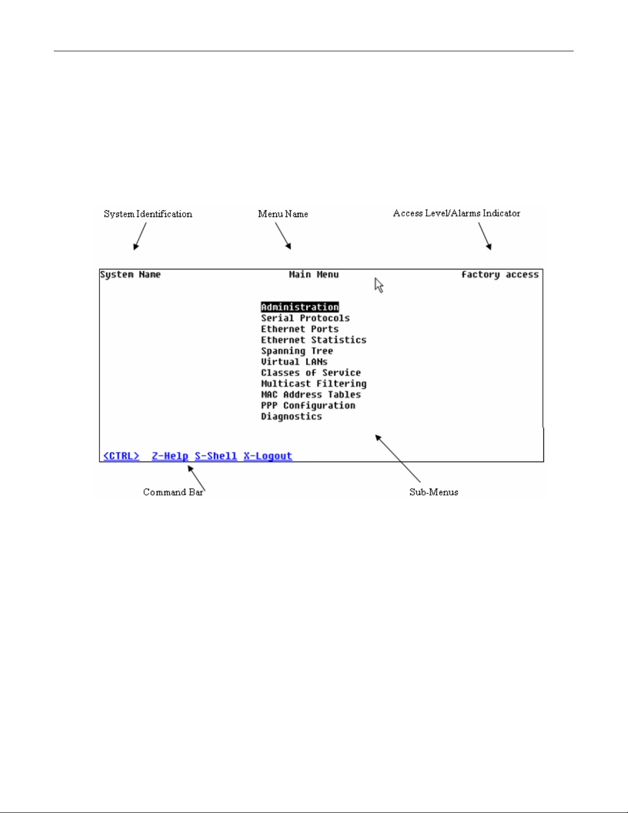
1.1.2 The Structure of the User Interface
The user interface is organized as a series of menus with an escape to a command line
interface (CLI) shell. Each menu screen presents the switch name (as proved by the System
Identification parameter), Menu Title, Access Level, Alarms indicator, Sub-Menus and
Command Bar.
Sub-menus are entered by selecting the desired menu with the arrow keys and pressing the
enter key. Pressing the escape key ascends to the parent menu.
Figure 1: Main Menu With Screen Elements Identified
The command bar offers a list of commands that apply to the currently displayed menu. These
commands include:
• <CTRL> Z to display help on the current command or data item
• <CTRL> S to switch to the CLI shell
• <CTRL> U/D to jump to next/previous page of a status display
The main menu also provides a <CTRL> X command, which will terminate the session. This
type of menu is accessible via serial consol, telnet session and SSH session.
1.1.3 Making Configuration Changes
When changing a data item the user selects the data item by the cursor keys and then pressing
the enter key. The cursor will change position to allow editing of the data item.
ROS™ v3.5 16 RS400
Page 17

Administration
Typing a new value after pressing enter always erases the old parameter value. The left and
right cursor keys can be used to position the edit point without erasing the old parameter value.
The up and down cursor keys can be used to cycle through the next higher and lower values for
the parameter.
After the parameter has been edited, press enter again to change other parameters. When all
desired parameters have been modified, press <CTRL> A to apply changes. The switch will
automatically prompt you to save changes when you leave a menu in which changes have been
made.
Some menus will require you to press <CTRL> I to insert a new record of information and
<CTRL> L to delete a record.
1.1.4 Updates Occur In Real Time
All configuration and display menus present the values at the current instant, automatically
updating if changed from other user interface sessions or SNMP. All statistics menus will display
changes to statistics as they occur.
1.1.5 Alarm Indications Are Provided
Alarms are events for which the user is notified through the Diagnostics submenu. All
configuration and display menus present an indication of the number of alarms (in the upper
right hand corner of the screen) as they occur, automatically updating as alarms are posted and
cleared.
1.1.6 The CLI Shell
The user interface provides a shell for operations that are more easily performed at the
command line. You may switch back and forth from the menu system and shell by pressing
<CTRL> S. For more information on the capabilities of the shell see the approapriate chapter of
this guide.
1.2 The ROS™ Secure Shell Server
1.2.1 Using a Secure Shell to Access the User Interface
SSH (Secure Shell) is a network protocol which provides a replacement for insecure remote
login and command execution facilities, such as telnet and remote shell. SSH encrypts traffic in
both directions, preventing traffic sniffing and password theft.
SSH protocol version 2 is implemented in ROS. The authentication method is keyboard
interactive password authentication. User name will not be verified in order to grant access to
SSH server. The passwords to be used for login are configured in Password Table and user’s
privileges are the same as for user logged in via the console port.
1.2.2 Using a Secure Shell to Transfer Files
ROS implements SFTP protocol over SSH to transfer files in secure manner. The file system is
created in one directory only. Also, all the files are created in the system at startup time and can
not be deleted, created, renamed. Files can be downloaded (upgraded) and uploaded (to be
analyzed outside of the unit).
The implemented commands are:
dir – a file directory
RS400 17 ROS™ v3.5
Page 18

Administration
get – upload from the switch and download to PC
put – upload from PC and download to PC
1.3 The ROS™ Web Server Interface
1.3.1 Using a Web Browser to Access the Web Interface
A web browser uses a secure communications method called Secure Socket Layer (SSL) to
encrypt traffic exchanged with its clients. Web server guarantees that communications with the
client is kept private. If client requires access via unsecure http port, it will be rerouted to the
secure port. The access via SSL will be granted any client that provides the correct password.
Your browser may complain about SSL Certificate that Web server issues. It happens because
the certificate that comes with the Web server is not issued by a recognized certificate authority.
However, network traffic is still encrypted.
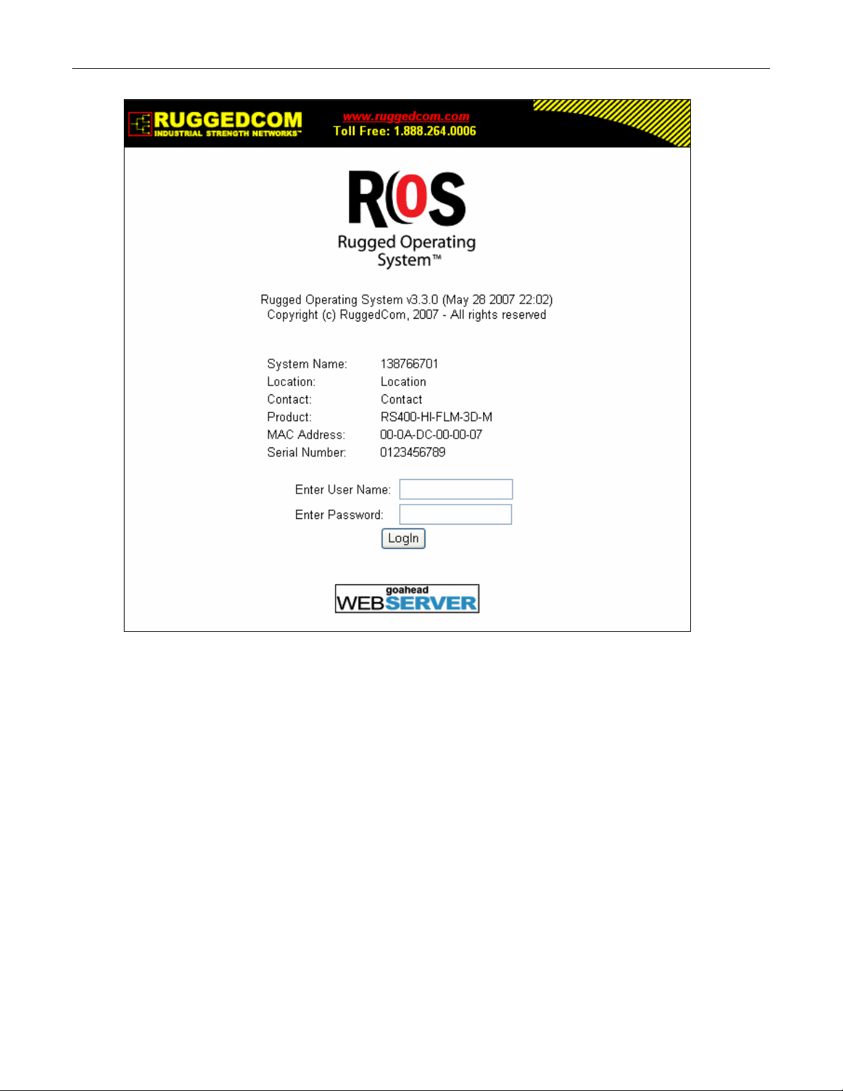
Start a web browser session and open a connection to the switch by entering a URL that
specifies its hostname or IP address (e.g. h
the login process by clicking on the “Login” link. The resulting page should be similar to that
presented below:
ttp://179.1.0.45). Once the switch is contacted, start
ROS™ v3.5 18 RS400
Page 19
Administration
Figure 2: Log in to The Device with a Web Browser
Enter the “admin” user name and the appropriate password for the admin user, and then click
on the “LogIn” button. The switch is shipped with a default administrator password of “admin”.
Once successfully logged in, the user will be presented with the main menu.
If the user wants to hide device information from the login screen, the ‘Login Banner’ option in
the System Identification menu must be set to ‘secure’.
RS400 19 ROS™ v3.5
Page 20

Administration
Figure 3: Log in to The Device with a Web Browser (secure login banner)
ROS™ v3.5 20 RS400
Page 21
Administration
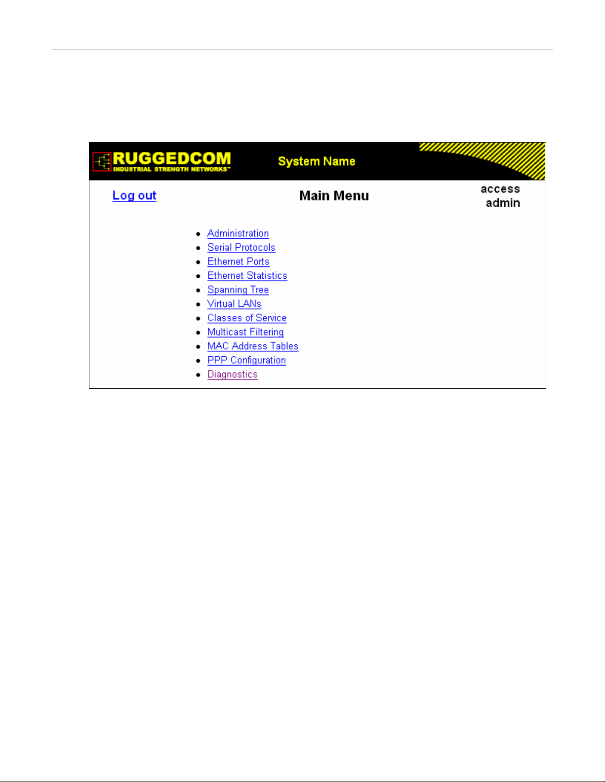
1.3.2 The Structure of the Web Interface
The user interface is organized as a series of linked web pages. The main menu provides the
links and allows them to be expanded to display lower level pages for a particular configuration
system.
Figure 4: Main Menu via Web Server Interface
Each web page presents the switch name (as proved by the System Identification parameter),
Menu Title link and user’s access name or Alarms link if any alarms are reported.
The Menu title link takes you to a page that provides help for the configuration parameters
provided by that page.
Alarms are events for which the user is notified by following the Alarms link (these alarms may
also be viewed and cleared through the Diagnostics submenu). All configuration and display
menus present an indication of the number of alarms (in the upper right hand corner of the
screen) as they occur, automatically updating as alarms are posted and cleared.
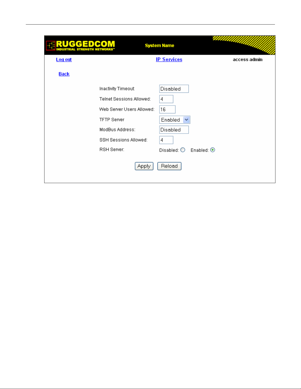
1.3.3 Making Configuration Changes
When changing a data item the user selects the data item by selecting the field to edit with the
mouse, entering a new value and clicking on the apply field. More than one parameter may be
modified at a time.
RS400 21 ROS™ v3.5
Page 22
Administration
Figure 5: Parameters Form Example
Some menus will require you to create or delete new records of information.
1.3.4 Updating Statistics Displays
You may click the refresh button to update statistics displays.
ROS™ v3.5 22 RS400
Page 23

Administration
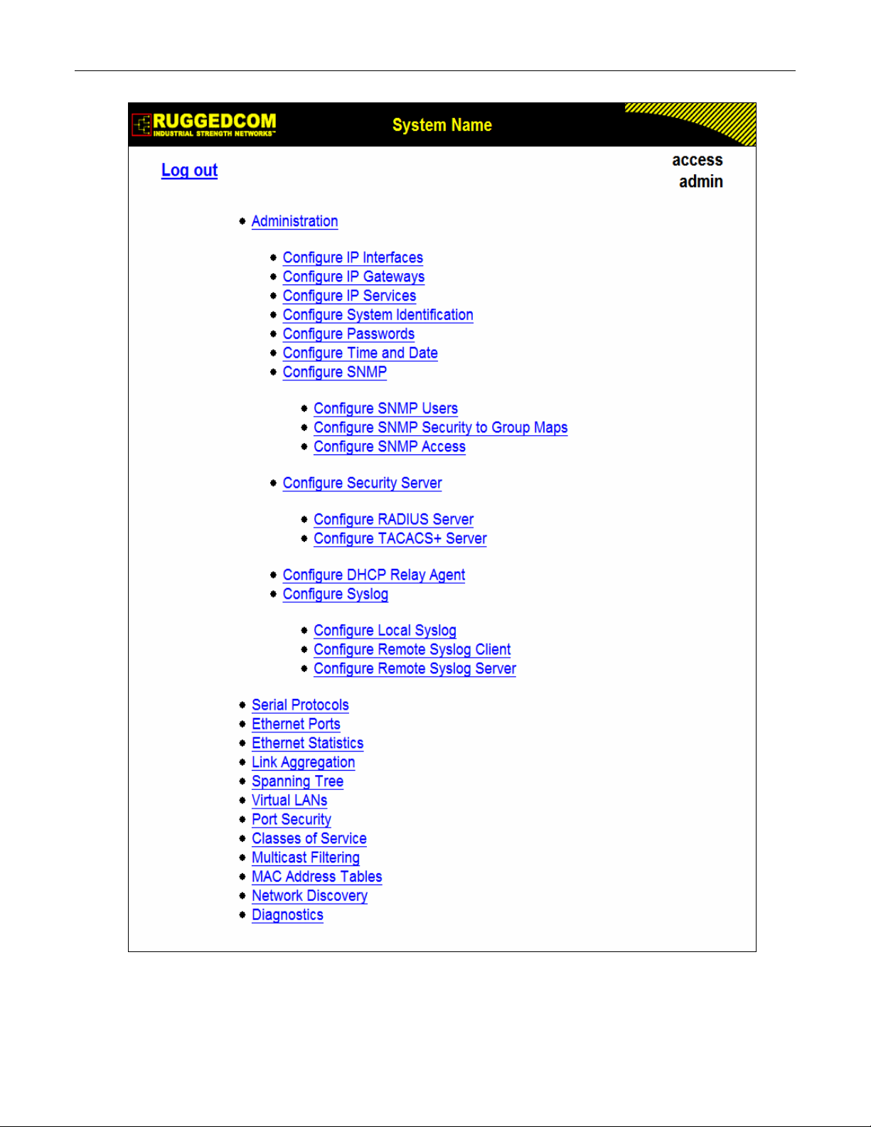
1.4 Administration Menu
The Administration menu provides ability to configure network and switch administration
parameters.
RS400 23 ROS™ v3.5
Page 24
Administration
Figure 6: Administration Menu
ROS™ v3.5 24 RS400
Page 25
Administration
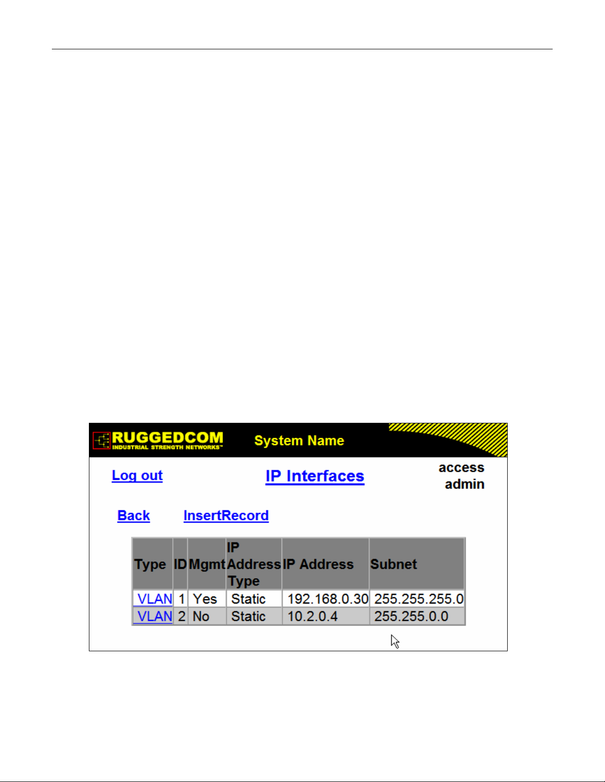
1.5 IP Interfaces
These parameters provide the ability to configure IP connection parameters such as address,
network, and mask.
The user can configure an IP Interface for each subnet (VLAN). One of the interfaces is
configured as management interface. IP services: TFTP server, SNMP server, Telnet server,
SSH server, RSH server, Web server, authentication using RADIUS server, DHCP client,
BOOTP client, DHCP relay agent will be available only via management interface. Different IP
interfaces MUST NOT overlap, e.g. the subnet mask must be unique.
15 IP interfaces can be configured in the device. In VLAN unaware mode, and in devices that do
not act as switches (as RMC30), only one IP interface can be configured.
On non-management interfaces, only static IP addresses can be assigned.
On management interface, the user can choose from the following IP Address type: Static,
DHCP, BOOTP and Dynamic. Static IP Address type refers to the manual assignment of IP
address while DHCP, BOOTP and Dynamic IP Address types refer to the automatic assignment
of IP address.
DHCP is widely used in LAN environments to dynamically assign IP addresses from a
centralized server, which reduces the overhead of administrating IP addresses.
TM
BOOTP is a subset of the DHCP protocol. ROS
The BOOTFILE represents any valid ROS
TM
the BOOTP server must match the corresponding ROS
supports transfer of a BOOTFILE via BOOTP.
file such as config.csv. The name of BOOTFILE on
TM
file.
The Dynamic IP Address type refers to a combination of the BOOTP and DHCP protocols.
Starting with BOOTP, the system will try BOOTP and DHCP in a round-robin fashion until it will
get a response from the corresponding server.
Figure 7: IP Interfaces Table
RS400 25 ROS™ v3.5
Page 26
Administration
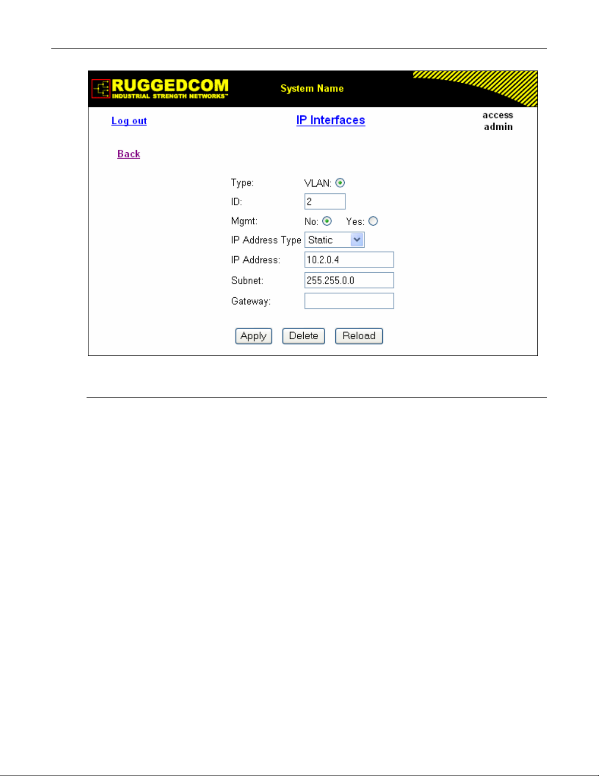
Figure 8: IP Interfaces Form
Note: The IP address and mask configured for management VLAN are not changed when resetting all
configuration parameters to defaults and will be assigned to default VLAN ID of 1. Changes to the
IP address take effect immediately. All IP connections in place at the time of an address change
will be lost.
Type
Synopsis: { VLAN }
Default: VLAN
Specifies the type of the interface for which this IP interface is created.
ID
Synopsis: 1 to 4094
Default: 1
Specifies the ID of the interface for which this IP interface is created. If interface type is VLAN,
represents VLAN ID.
Mgmt
Synopsis: { No, Yes }
Default: No
Specifies whether the IP interface is the device management interface.
IP Address Type
Synopsis: { Static, Dynamic, DHCP, BOOTP }
Default: Static
Specifies whether the IP address is static or dynamically assigned via DHCP or BOOTP. Option
ROS™ v3.5 26 RS400
Page 27

Administration
DYNAMIC is a common case of dynamically assigned IP address. It switches between BOOTP
and DHCP until it gets the response from the relevant server.
Must be static for non management interfaces
IP Address
Synopsis: ###.###.###.### where ### ranges from 0 to 255
Default: 192.168.0.1
Specifies the IP address of this device. An IP address is a 32-bit number that is notated by
using four numbers from 0 through 255, separated by periods. Only a unicast IP address is
allowed which ranges from 1.0.0.0 to 233.255.255.255
Subnet
Synopsis: ###.###.###.### where ### ranges from 0 to 255
Default: 255.255.255.0
Specifies the IP subnet mask of this device. An IP subnet mask is a 32-bit number that is
notated by using four numbers from 0 through 255, separated by periods. Typically, subnet
mask numbers use either 0 or 255 as values (e.g. 255.255.255.0) but other numbers can
appear.
RS400 27 ROS™ v3.5
Page 28
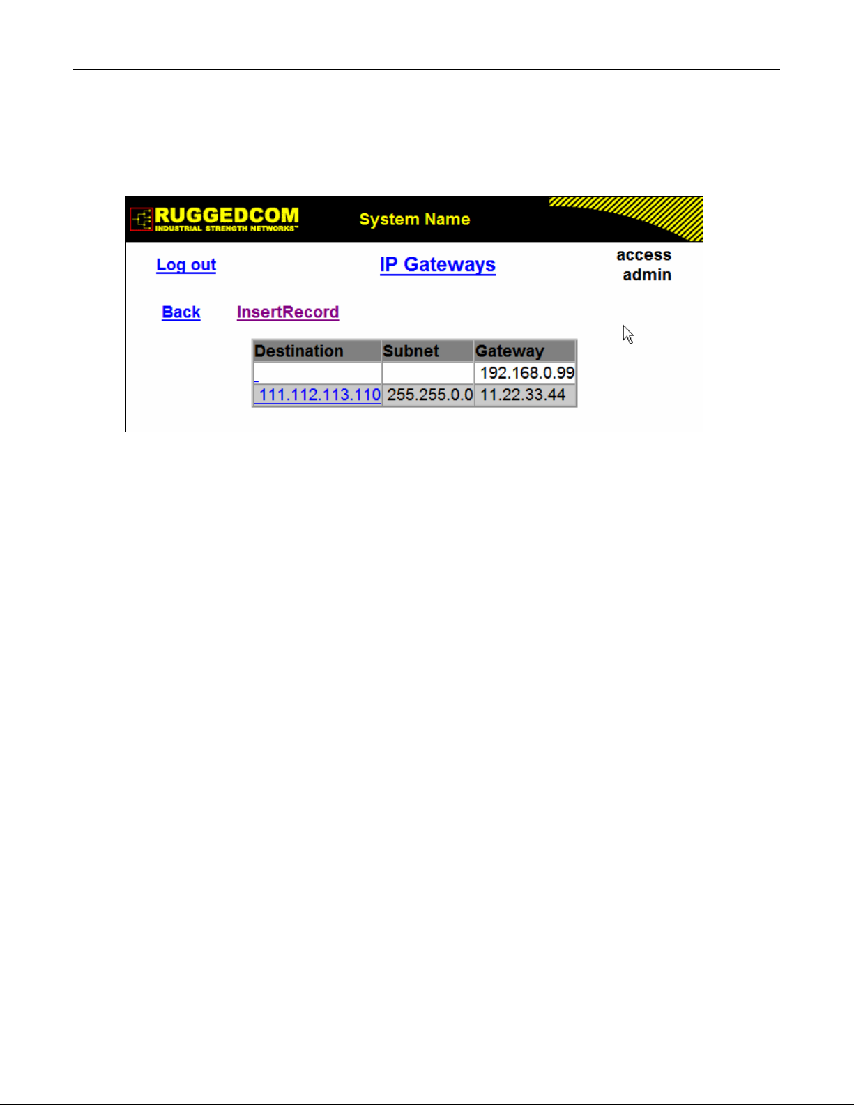
Administration
1.6 IP Gateways
These parameters provide the ability to configure gateways. A maximum of 10 gateways can be
configured. When both the Destination and Subnet fields are both 0.0.0.0 (displayed as blank
space), the gateway is a default gateway.
Figure 9: IP Gateways Form
Destination
Synopsis: ###.###.###.### where ### ranges from 0 to 255
Default: 0.0.0.0
Specifies the IP address of the destination device. An IP address is a 32-bit number that is
notated by using four numbers from 0 through 255, separated by periods.
Subnet
Synopsis: ###.###.###.### where ### ranges from 0 to 255
Default: 0.0.0.0
Specifies the IP subnet mask of the destination. An IP subnet mask is a 32-bit number that is
notated by using four numbers from 0 through 255, separated by periods. Typically, subnet
mask numbers use either 0 or 255 as values (e.g. 255.255.255.0) but other numbers can
appear.
Gateway
Synopsis: ###.###.###.### where ### ranges from 0 to 255
Default: 0.0.0.0
Specifies the gateway IP address. The gateway address must be on the same IP subnet as this
device.
Note: The default gateway configuration will not be changed when resetting all configuration parameters
to defaults.
ROS™ v3.5 28 RS400
Page 29
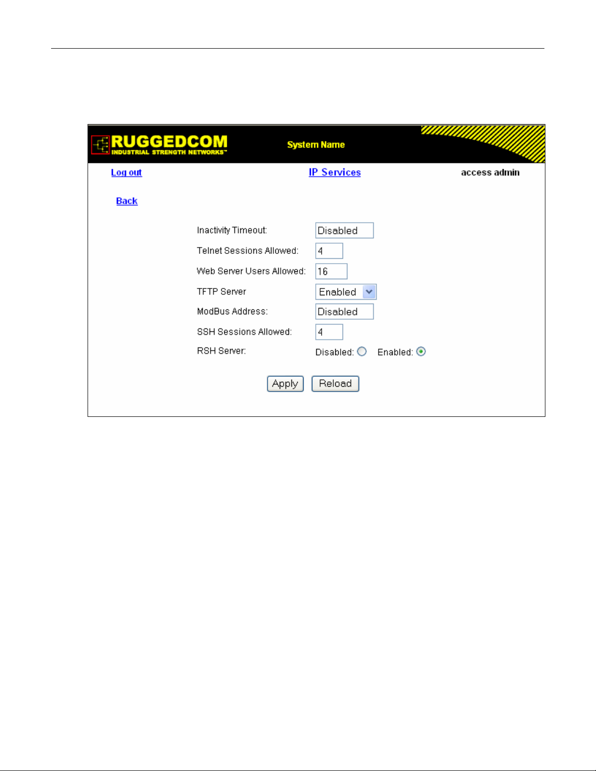
Administration
1.7 IP Services
These parameters provide the ability to configure properties for IP services provided by the
device.
Figure 10: IP Services Form
Inactivity Timeout
Synopsis: 1 to 60 or { Disabled }
Default: 5 min
Specifies when the console will timeout and display the login screen if there is no user activity. A
value of zero disables timeouts for console and Telnet users. For Web Server users maximum
timeout value is limited to 30 minutes.
Telnet Sessions Allowed
Synopsis: 0 to 4
Default: 4
Limits the number of Telnet sessions. A value of zero prevents any Telnet access.
Web Server Users Allowed
Synopsis: 1 to 16
Default: 16
Limits the number of simultaneous web server users.
TFTP Server
Synopsis: { Disabled, Get Only, Enabled }
Default: Get Only
As TFTP is a very insecure protocol, this parameter allows the user to limit or disable TFTP
RS400 29 ROS™ v3.5
Page 30

Administration
Server access.
DISABLED - disables read and write access to TFTP Server
GET ONLY - only allows to read files via TFTP Server
ENABLED - allows to read and write files via TFTP Server
ModBus Address
Synopsis: 1 to 254 or { Disabled }
Default: Disabled
Determines the Modbus address to be used for Management through Modbus.
SSH Sessions Allowed
Synopsis: 1 to 4
Default: 4
Limits the number of SSH sessions.
RSH Server
Synopsis: { Disabled, Enabled }
Default: Enabled
Disables/enables Remote Shell access.
ROS™ v3.5 30 RS400
Page 31

Administration
1.8 System Identification
The system identification is displayed in the sign-on screen and in the upper left hand corner of
all ROS™ screens.
Figure 11: System Identification Form
System Name
Synopsis: Any 19 characters
Default: System Name
The system name is displayed in all ROS menu screens. This can make it easier to identify the
switches within your network provided that all switches are given a unique name
Location
Synopsis: Any 49 characters
Default: Location
The location can be used to indicate the physical location of the switch. It is displayed in the
login screen as another means to ensure you are dealing with the desired switch.
Contact
Synopsis: Any 49 characters
Default: Contact
The contact can be used to help identify the person responsible for managing the switch. You
can enter name, phone number, email, etc. It is displayed in the login screen so that this person
may be contacted should help be required.
Login Banner
Synopsis: { Full, Secure }
Default: Full
Provides ability to hide information displayed in RuggedCom banner on login screen.
The user can configure the device to display either the full RuggedCom banner or a secure
version of banner.
RS400 31 ROS™ v3.5
Page 32

Administration
1.9 Passwords
These parameters provide the ability to configure parameters for authorized and authenticated
access to the device services (HMI via Serial Console, Telnet, SSH, RSH, Web Server). The
access to the switch can be authorized and authenticated via RADIUS server, or using locally
configured passwords, that are always related to the username and access level.
Note that access via Serial Console is always going to be authorized first using local settings. If
match has not been not found, RADIUS will be used if enabled. For all other services, if
RADIUS is enabled for authentication and authorization, local setting will not be used at all.
To access unit, username and password must be provided.
Three usernames and passwords can be configured. They correspond to three access levels,
which provide or restrict access to change settings and execute various commands within the
device.
• guest users can view most settings, but may not change settings or run commands
• operator cannot change settings, but can reset alarms, clear statistics and logs
• admin user can change all the settings and run commands
Figure 12: Passwords Form
Auth Type
Synopsis: { Local, RADIUS }
Default: Local
Password can be authenticated using locally configured values, or remote RADIUS server.
Setting value to 'RADIUS' will require RADIUS Server Table to be configured.
ROS™ v3.5 32 RS400
Page 33

Administration
Guest Username
Synopsis: 15 character ascii string
Default: guest
Related password is in field Guest Password; view only, cannot change settings or run any
commands.
Guest Password
Synopsis: 15 character ascii string
Default: guest
Related username is in field Guest Username; view only, cannot change settings or run any
commands.
Operator Username
Synopsis: 15 character ascii string
Default: operator
Related password is in field Oper Password; cannot change settings; can reset alarms,
statistics, logs, etc.
Operator Password
Synopsis: 15 character ascii string
Default: operator
Related username is in field Oper Username; cannot change settings; can reset alarms,
statistics, logs, etc.
Admin Username
Synopsis: 15 character ascii string
Default: admin
Related password is in field Admin Password; full read/write access to all settings and
commands.
Admin Password
Synopsis: 15 character ascii string
Default: admin
Related username is in field Admin Username; full read/write access to all settings and
commands.
RS400 33 ROS™ v3.5
Page 34

Administration
1.10 Time and Date
Device time, date and time zone can be set via this form. The device can also be configured to
periodically contact an (S)NTP server to correct for drift in the onboard clock.
Each RuggedCom unit can act as a unicast SNTP server and/or SNTP client. The SNTP server
will respond to the unicast SNTP requests received from the units where it’s address is
configured as NTP Server Address. Server itself can be synchronized by higher level NTP
server.
Figure 13: Time and Date Form
Time
Synopsis: HH:MM:SS
This parameter allows for both the viewing and setting of the local time.
Date
Synopsis: MMM DD, YYYY
This parameter allows for both the viewing and setting of the local date.
Time Zone
Synopsis: {
UTC-12:00 (Eniwetok, Kwajalein), UTC-11:00 (Midway Island, Samoa),
UTC-10:00 (Hawaii), UTC-9:00 (Alaska), UTC-8:00 (Los Angelos, Vancouver),
UTC-7:00 (Calgary, Denver), UTC-6:00 (Chicago, Mexico City),
UTC-5:00 (New York, Toronto), UTC-4:00 (Caracas, Santiago), UTC-3:30 (Newfoundland),
UTC-3:00 (Brasilia, Buenos Aires), UTC-2:00 (Mid Atlantic), UTC-1:00 (Azores),
UTC-0:00 (Lisbon, London), UTC+1:00 (Berlin, Paris, Rome),
UTC+2:00 (Athens, Cairo, Helsinki), UTC+3:00 (Bagdad, Moscow),
UTC+3:30 (Teheran), UTC+4:00 (Abu Dhabi, Kazan, Muscat),
UTC+4:30 (Kabul), UTC+5:00 (Islamabad, Karachi),
ROS™ v3.5 34 RS400
Page 35

Administration
UTC+5:30 (Calcutta, New Delhi), UTC+5:45 (Kathmandu),
UTC+6:00 (Almaty, Dhaka), UTC+6:30 (Rangoon),
UTC+7:00 (Bangkok, Hanoi), UTC+8:00 (Beijing, Hong Kong)
UTC+9:00 (Seoul, Tokyo), UTC+9:30 (Adelaide, Darwin),
UTC+10:00 (Melbourne, Sydney), UTC+11:00 (Magadan, New Caledonia),
UTC+12:00 (Auckland, Fiji) }
Default: UTC-0:00 (Lisbon, London)
This setting allows for the conversion of UTC (Universal Coordinated Time) to local time.
NTP Server Address
Synopsis: ###.###.###.### where ### ranges from 0 to 255
Default:
This parameter specifies the IP address of an (S)NTP server ((Simple) Network Time Protocol);
programming an address of '0.0.0.0' disables SNTP requests. This device is an SNTP client
which allows for only one server. If an server address is programmed then a manual setting of
the time will be overwritten at the next update period.
NTP Update Period
Synopsis: 1 to 1440
Default: 60 min
This setting determines how frequently the (S)NTP server is polled for a time update. If the
server cannot be reached, three attempts are made at one minute intervals and then an alarm is
generated at which point the programmed rate is resumed.
RS400 35 ROS™ v3.5
Page 36

Administration
1.11 SNMP Management
ROS supports Simple Network Management Protocol Version 3 (SNMPv3). This protocol
provides secure access to devices by a combination of authentication and encrypting packets
over the network. The security features provided are:
• message integrity - ensuring that a packet has not been tampered with in-transit
• authentication – determining the message is from a valid source
• encryption – scrambling the contents of a packet to prevent it from being seen by an
unauthorized source.
SNMPv3 provides security models and security levels. A security model is an authentication
strategy that is set up for a user and the group in which the user resides. A security level is a
permitted level of security within a security model. A combination of a security model and
security level will determine which security mechanism is employed when handling an SNMP
packet.
Note the following about SNMPv3 protocol:
• each user belongs to a group
• a group defines the access policy for a set of users
• an access policy defines what SNMP objects can be accessed for: reading, writing and
creating, notifications
• a group determines the list of notifications its users can receive
• a group also defines the security model and security level for its users.
1.11.1 SNMP Users
These parameters provide the ability to configure users for the local SNMPv3 engine. Note that,
if employed security level is SNMPv1 or SNMPv2, user Name represents a community name for
authentication or sending traps. Up to 32 entries can be configured.
Figure 14: SNMP User Table
ROS™ v3.5 36 RS400
Page 37

Administration
Figure 15: SNMP User Form
Name
Synopsis: Any 32 characters
Default: initial
The name of the user. This is the User-based Security Model dependent security ID
IP Address
Synopsis: ###.###.###.### where ### ranges from 0 to 255
Default:
The IP address of the user's SNMP management station if it is configured to receive traps and
notifications.
Auth Protocol
Synopsis: { noAuth, HMACMD5 }
Default: noAuth
An indication of whether messages sent on behalf of this user to/from SNMP engine, can be
authenticated, and if so, the type of authentication protocol which is used.
Priv Protocol
Synopsis: { noPriv, CBC-DES }
Default: noPriv
An Indication of whether messages sent on behalf of this user to/from SNMP engine can be
protected from disclosure, and if so, the type of privacy protocol which is used.
Auth Key
Synopsis: 31 character ascii string
Default:
The secret authentication key (password) that must be shared with SNMP client.
RS400 37 ROS™ v3.5
Page 38
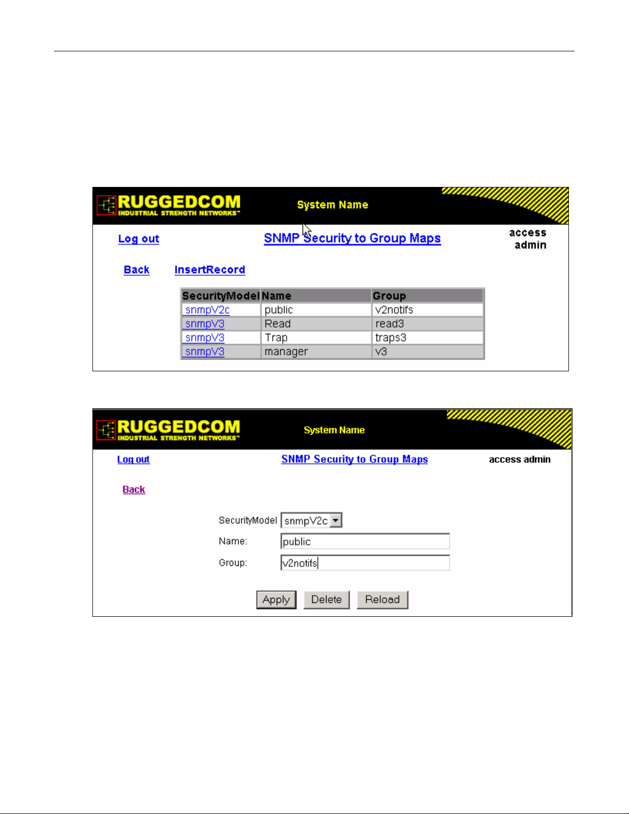
Administration
Priv Key
Synopsis: 31 character ascii string
Default:
The secret encryption key (password) that must be shared with SNMP client
1.11.2 SNMP Security to Group Maps
Entries in this table map configuration of security model and security name (user) into a group
name, which is used to define an access control policy. Up to 32 entries can be configured.
Figure 16: SNMP Security to Group Maps Table
Figure 17: SNMP Security to Group Maps Form
SecurityModel
Synopsis: { snmpV1, snmpV2c, snmpV3 }
Default: snmpV3
The Security Model that provides name referenced in this table.
Name
Synopsis: Any 32 characters
ROS™ v3.5 38 RS400
Page 39

Administration
Default:
The user name which is mapped by this entry to the specified group name.
Group
Synopsis: Any 32 characters
Default:
The group name to which the security model and name belong. This name is used as index to
SNMPv3 VACM Access Table.
1.11.3 SNMP Access
These parameters provide the ability to configurate access rights for groups.To determine
whether access is allowed, one entry from this table needs to be selected and the proper
viewName from that entry must be used for access control checking. View names are
predifined:
• noView - access is not allowed
• V1Mib - SNMPv3 MIBs excluded
• allOfMibs - all supported MIBs are included.
Figure 18: SNMP Access Table
RS400 39 ROS™ v3.5
Page 40

Administration
Figure 19: SNMP Access Form
Group
Synopsis: Any 32 characters
Default:
The group name to which the security model and name belong. This name is used as index to
SNMPv3 VACM Access Table.
SecurityModel
Synopsis: { snmpV1, snmpV2c, snmpV3 }
Default: snmpV3
In order to gain the access rights allowed by this entry, configured security model must be in
use.
SecurityLevel
Synopsis: { noAuthNoPriv, authNoPriv, authPriv }
Default: noAuthNoPriv
The minimum level of security reqwuired in order to gain the access rights allowed by this entry.
A security level of noAuthNoPriv is less than authNoPriv, which is less tha authPriv.
ReadViewName
Synopsis: { noView, V1Mib, allOfMib }
Default: noView
This parameter identifies the MIB tree(s) to which this entry authorizes read access. If the value
is noView, then no read access is granted.
WriteViewName
Synopsis: { noView, V1Mib, allOfMib }
Default: noView
This parameter identifies the MIB tree(s) to which this entry authorizes write access. If the value
is noView, then no write access is granted.
ROS™ v3.5 40 RS400
Page 41

Administration
NotifyViewName
Synopsis: { noView, V1Mib, allOfMib }
Default: noView
This parameter identifies the MIB tree(s) to which this entry authorizes access for notifications. If
the value is noView, then no access for notifications is granted.
RS400 41 ROS™ v3.5
Page 42

Administration
1.12 RADIUS
RADIUS (Remote Authentication Dial In User Service) is used to provide centralized
authentication and authorization for network access. ROS assigns a privilege level of Admin,
Operator or Guest to a user who presents a valid username and password. The number of
users who can access the ROS server is ordinarily dependent on the number of user records
which can be configured on the server itself. ROS can also, however, be configured to pass
along the credentials provided by the user to be remotely authenticated by a RADIUS server. In
this way, a single RADIUS server can centrally store user data and provide authentication and
authorization service to multiple ROS servers needing to authenticate connection attempts.
1.12.1 RADIUS overview
RADIUS (described in RFC 2865) is a UDP-based protocol is used for carrying authentication,
authorization, and configuration information between a Network Access Server which desires to
authenticate its links and a shared Authentication Server. RADIUS is also used also widely
utilized in conjunction with 802.1x for port security using EAP
A RADIUS server can act as a proxy client to other RADIUS servers or other kinds of
authentication servers.
Unlike TACACS+, authorization and authentication functionality is supported in by RADIUS in
the same packet frame. TACACS+ actually separates authentication from authorization into
separate packets.
(See Appendix A).
On receiving an authentication-authorization request from client in an “Access-Request” packet
RADIUS server checks the conditions configured for received username-password combination
in the user database. If all the conditions are met, the list of configuration values for the user is
placed into an “Access-Accept” packet. These values include the type of service (e.g. SLIP,
PPP, Login User) and all the necessary values to deliver the desired service.
1.12.2 User Login Authentication and Authorization
A RADIUS Server can be used to authenticate and authorize access to the device’s services,
such as HMI via Serial Console, Telnet, SSH, RSH, Web Server (see Password Configuration).
ROS implements a RADIUS Client which uses the Password Authentication Protocol (PAP) to
verify access. Attributes sent to a RADIUS Server are:
• user name
• user password
• service type: Login
• vendor specific, currently defined as following:
vendor ID: Ruggedcom Inc. enterprise number (15004) assigned by the Internet Assigned
Numbers Authority (IANA)
string, sub-attribute containing specific values:
subtype: 1 (vendor’s name subtype)
length: 11 (total length of sub-attribute of subtype 1)
ASCII string “RuggedCom”
Two RADIUS servers (Primary and Secondary) are configurable per device. If the Primary
Server is not reachable, the device will automatically fall back to the Secondary server to
complete the authorization process.
ROS™ v3.5 42 RS400
Page 43

Administration
The vendor specific attribute is used to determine the access level from the server, which may
be configured at the RADIUS server with following information:
• Vendor ID: Ruggedcom Inc. enterprise number (15004) assigned by Internet Assigned
Numbers Authority (IANA)
• Sub-attribute Format: String
• Vendor Assigned Sub-Attribute Number: 2
• Attribute value – any one of: admin, operator, guest
Note: If no access level is received in the response packet from the server then no access will be granted
to the user
Example RuggedCom Dictionary for a freeRadius server:
VENDOR RuggedCom 15004
BEGIN-VENDOR RuggedCom
ATTRIBUTE RuggedCom-Privilege-level 2 string
END-VENDOR RuggedCom
Sample entry for user “admin” Adding Users:
admin Auth-Type := Local, User-Password == "admin"
RuggedCom-Privilege-level = "admin
1.12.3 802.1X Authentication (not supported in RS400, N/A for RMC30)
RADIUS Server is also used to authenticate access on ports with 802.1X security support.
Attributes sent to RADIUS Server in RADIUS Request are:
• user name, derived from client’s EAP identity response
• NAS IP address
• service type: framed
• framed MTU:1500 (maximum size of EAP frame, which is the size of Ethernet frame)
• EAP message
• vendor specific attribute, as described above
RADIUS messages are sent as UDP messages. Switch and RADIUS server must use the same
authentication and encryption key.
RS400 43 ROS™ v3.5
Page 44

Administration
1.12.4 Radius Server Configuration
Figure 20: RADIUS Server summary
Figure 21: RADIUS Server Form
Server
Synopsis: Any 8 characters
Default: Primary
This field tells whether this configuration is for a Primary or a Backup Server
IP Address
Synopsis: ###.###.###.### where ### ranges from 0 to 255
ROS™ v3.5 44 RS400
Page 45

Administration
Default:
The RADIUS server IP Address.
Auth UDP Port
Synopsis: 1 to 65535
Default: 1812
The authentication UDP Port on RADIUS server.
Auth Key
Synopsis: 31 character ascii string
Default:
The authentication key shared with RADIUS server. It is used to encrypt any passwords that are
sent between the switch and RADIUS server.
RS400 45 ROS™ v3.5
Page 46

Administration
1.13 TACACS+
TACACS+ (Terminal Access Controller Access-Control System Plus) is a TCP-based access
control protocol that provides authentication, authorization and accounting services to routers,
network access servers and other networked computing devices via one or more centralized
servers. It is based on, but is not compatible with, the older TACACS protocol. TACACS+ has
generally replaced its predecessor in more recently built or updated networks, although
TACACS and XTACACS are still used on many older networks. Note that RuggedCom’s
TACACS+ client implementation always has encryption enabled.
1.13.1 User Login Authentication and Authorization
A TACACS+ server can be used to authenticate and authorize access to the device’s services,
such as HMI via Serial Console, Telnet, SSH, RSH, Web Server (see Password Configuration).
Username and Password are sent to the configured TACACS+ Server.
Two TACACS+ servers (Primary and Secondary) are configurable per device. If the Primary
Server is not reachable, the device will automatically fall back to the Secondary server to
complete the authorization process.
• The TACACS+ standard priv_lvl attribute will be used to grant access to the device:
priv_lvl=15 represents an access level of “admin”
1 < priv_lvl < 15 represents an access level of “operator” (i.e. any value from 2 to 14)
priv_lvl=1 represents an access level of “guest”
Note: If no access level is received in the response packet from the server then no access will be granted
to the user
1.13.2 TACACS+ Server Configuration
Figure 22: TACACS+ Server summary
ROS™ v3.5 46 RS400
Page 47

Administration
Figure 23: TACACS+ Server Form
Server
Synopsis: Any 8 characters
Default: Primary
This field tells whether this configuration is for a Primary or a Backup Server
IP Address
Synopsis: ###.###.###.### where ### ranges from 0 to 255
Default:
The TACACS+ server IP Address.
Auth TCP Port
Synopsis: 1 to 65535
Default: 49
The authentication TCP Port on TACACS+ server.
Auth Key
Synopsis: 31 character ascii string
Default:
The authentication key shared with TACACS+ server. It is used to encrypt any passwords that
are sent from the switch to TACACS+ server.
RS400 47 ROS™ v3.5
Page 48

Administration
1.14 DHCP Relay Agent (N/A for RMC30)
DHCP Relay Agent is a device that forwards DHCP packets between clients and servers when
they are not on the same physical LAN segment or IP Subnet. The feature is enabled if DHCP
Server IP address and set of access ports are configured.
DHCP Option 82 provides a mechanism for assigning IP Address based on location of the client
device is in the network. Information about client’s location can be sent along with the DHCP
request to the server. The DHCP server makes a decision about IP Address to be assigned,
based on this information.
DHCP Relay Agent takes the broadcast DHCP requests from clients received on configured
access port and inserts the relay agent information option (option 82) in the packet. The option
82 contains the VLAN (2 bytes) and the port number of access port (2 bytes) (the circuit ID suboption) and switch’s MAC address (the remote ID sub-option). These information uniquely
define access port’s position in the network.
DHCP Server supporting DHCP option 82 sends unicast reply and echoes option 82. The
DHCP Relay Agent removes option 82 field and broadcasts the packet to the port from which
the original request was received.
These parameters provide ability to configure switch to act as Relay Agent for DHCP Option 82.
DHCP Relay Agent is communicating to the server on management interface. The agent’s IP
address is the address configured for the management interface.
Figure 24: DHCP Relay Agent Form
DHCP Server Address
Synopsis: ###.###.###.### where ### ranges from 0 to 255
Default:
This parameter specifies the IP address of the DHCP server to which DHCP queries will be
forwarded from this Relay Agent.
ROS™ v3.5 48 RS400
Page 49

Administration
DHCP Client Ports
Synopsis: Any combination of numbers valid for this parameter
Default: None
This parameter specifies ports where DHCP clients are connected.
Examples:
All - all ports of the switch can have DHCP clients connected.
2,4-6,8 - ports 2,4,5,6 and 8 can have DHCP clients connected
1.15 Syslog
The syslog provides users the ability to configure local syslog and remote syslog. The remote
syslog protocol, defined in RFC 3164, provides a UDP/IP based transport to allow a device to
send event notification messages across IP networks to event message collectors, also known
as syslog servers. The protocol is simply designed to transport these event messages from the
generating device to the collector.
Syslog client resides in ROS
Remote Syslog provides the ability to configure:
• IP address(es) of collector(s)
• Source UDP port
• Destination UDP port per collector
• Syslog source facility ID per collector (same value for all ROSTM modules)
• Filtering severity level per collector (in case different collectors are interested in syslog
reports with different severity levels)
TM
and supports up to 5 collectors (syslog servers). The ROSTM
1.15.1 Configuring Local Syslog
The local syslog configuration enables users to control what level of syslog information will be
logged. Only the messages with higher than or equal to the configured severity level are written
to the syslog.txt file in the unit.
Figure 25: Local Syslog Form
Local Syslog Level
Synopsis: { EMERGENCY, ALERT, CRITICAL, ERROR, WARNING, NOTICE, INFORMATION
AL, DEBUGGING }
Default: DEBUGGING
RS400 49 ROS™ v3.5
Page 50

Administration
Syslog severity level - {EMERGENCY, ALERT, CRITICAL, ERROR, WARNING, NOTICE,
INFORMATIONAL, DEBUGGING}.
1.15.2 Configuring Remote Syslog Client
Figure 26: Remote Syslog Client Form
UDP Port
Synopsis: 1025 to 65535 or { 514 }
Default: 514
The local UDP port through which client sends information to server(s).
1.15.3 Configuring Remote Syslog Server
Figure 27: Remote Syslog Server Table
ROS™ v3.5 50 RS400
Page 51

Administration
Figure 28: Remote Syslog Server Form
IP Address
Synopsis: ###.###.###.### where ### ranges from 0 to 255
Default:
Syslog server IP Address.
UDP Port
Synopsis: 1025 to 65535 or { 514 }
Default: 514
The UDP port number on which remote server listens.
Facility
Synopsis: { USER, LOCAL0, LOCAL1, LOCAL2, LOCAL3, LOCAL4, LOCAL5, LOCAL6, LOCA
L7 }
Default: LOCAL7
Syslog facility name - { USER, LOCAL0, LOCAL1, LOCAL2, LOCAL3, LOCAL4, LOCAL5,
LOCAL6, LOCAL7 }.
Severity
Synopsis: { EMERGENCY, ALERT, CRITICAL, ERROR, WARNING, NOTICE, INFORMATION
AL, DEBUGGING }
Default: DEBUGGING
Syslog severity level - {EMERGENCY, ALERT, CRITICAL, ERROR, WARNING, NOTICE,
INFORMATIONAL, DEBUGGING}.
RS400 51 ROS™ v3.5
Page 52

Administration
1.16 Troubleshooting
Problem One
I have configured the IP address and a gateway. I am pinging the switch but it is not
responding. I am sure the switch is receiving the ping because it’s port LEDs are flashing
and the statistics menu shows the pings. What is going on?
Is the switch being pinged through a router? If so, the switch gateway address must be
configured. The following figure illustrates the problem.
Figure 29: Using A Router As A Gateway
The router is configured with the appropriate IP subnets and will forward the ping from the
workstation to the switch. When the switch responds, however, it will not know which its
interfaces to use in order to reach the workstation and will drop the response. Programming a
gateway of 10.0.0.1 will cause the switch to forward un-resolvable frames to the router.
This problem will also occur if the gateway address is not configured and the switch tries to
raise an SNMP trap to a host that is not on the local subnet
ROS™ v3.5 52 RS400
Page 53

Serial Protocols
2 Serial Protocols
RuggedCom devices support following serial protocols:
• Raw Socket serial encapsulation
• Preemptive Raw Socket
• TCPModbus (client and server modes)
• DNP 3
• Microlok
• WIN and TIN
• Mirrored Bits
2.1 Serial Protocols Overview
Baud rates on serial interfaces can be configured in range of 100 to 230400 bps. A “turnaround”
time is supported to enforce minimum times between messages sent out the serial port.
If port is set to force half duplex mode, while sending data all received data will be discarded. To
set this mode, port must natively work in full duplex mode.
To transport protocol messages through the network, either TCP/IP or UDP/IP transport can be
used. The exception is TCPModbus protocol that can not be employed over UDP.
The setting of Differentiated Services Code Point (DSCP) in the IP header is provided for
TCP/IP and UDP/IP transport in the egress direction only.
Debugging facilities include statistics and tracing information on a serial port and/or network
transport.
2.1.1 ‘Raw Socket’ protocol features
• A means to transport streams of characters from one serial port, over an IP network to
another serial port
• XON/XOFF flow control
• Configurable local and remote IP port numbers per serial port
• Point-to-point UDP transactions
• TCP accept or request connection mode
• Point-to-point TCP connection mode and a broadcast connection mode in which up to 64
remote servers may connect to a central server
• Packetization and sending data on a full packet, a specific character or upon a timeout
• Configurable “turnaround” time to enforce minimum time between messages sent out the
serial port.
2.1.2 ‘Preemptive Raw Socket’ protocol features
• A means to transport streams of characters from one serial port, over an IP network to
another serial port
• Configurable local and remote IP port numbers per serial port
• TCP accept or request one permanent connection on configured IP address
RS400 53 ROS™ v3.5
Page 54

Serial Protocols
• TCP accept one dynamic connection from different IP address
• Dynamic connection activity timer controlled
• XON/XOFF flow control for permanent connection
• ‘Packetization’ trigger based on a full packet, a specific character or upon a timeout for each
connection
2.1.3 ‘Modbus’ protocol features
• Operation in TCPModbus server gateway or client gateway mode
• Multi-master mode on server
• Configurable behavior in for sending exceptions
• Full control over ‘packetization’ timers
• Configurable Auxiliary IP port number for applications that do not support port 502
2.1.4 ‘DNP’ protocol features
• ‘Packetization’ per protocol specification
• CRC checking in message headers received from the serial port
• Local and remote source address learning
2.1.5 ‘Microlok’ protocol features
• ‘Packetization’ per protocol specification
2.1.6 ‘WIN’ protocol features
• ‘Packetization’ following the protocol requirements
• CRC checking for messages received from the serial port
2.1.7 ‘TIN’ protocol features
• Support for two modes of TIN protocol
• ‘Packetization’ following the protocol requirements
• CRC checking for messages received from the serial port
• Remote source address learning, specific for two different modes
ROS™ v3.5 54 RS400
Page 55

Serial Protocols
2.2 Serial Protocols Operation
2.2.1 Serial Encapsulation Applications
2.2.1.1 Character Encapsulation (Raw Socket)
Character encapsulation is used any time a stream of characters must be reliably transported
across a network.
The character streams can be created by any type of device. The baud rates supported at either
server need not be the same. If configured, the server will obey XON/XOFF flow control from
the end devices.
Figure 30: Character Encapsulation
2.2.1.2 RTU Polling
The following applies to a variety of RTU protocols including Modbus ASCII and DNP.
Note: Users of protocols supported by Ruggedcom devices are advised to use applications for used
protocols.
The host equipment may connect to a RuggedServer™ via a serial port, may use a port
redirection package or may connect natively to the network.
Figure 31: RTU Polling
RS400 55 ROS™ v3.5
Page 56

Serial Protocols
If RuggedServer™ is used at the host end, it will wait for a request from the host, encapsulate it
in an IP Datagram and send it to the remote side. There, the remote RuggedServer™ will
forward the original request to the RTU. When the RTU replies the RuggedServer™ will forward
the encapsulated reply back to the host end.
RuggedServer™ maintains configurable timers to help decide if replies and requests are
complete.
RuggedServer™ will also handle the process of line-turnaround when used with RS485. It is
important to mention that unsolicited messages from RTUs in half-duplex mode can not be
supported reliably. Message processing time includes sending a message over RS485, a
packtimer and a turnaround time. In order to handle half-duplex mode reliably, the turnaround
time must be configured long enough to allow an expected response to be received. Any other
messages will not be sent to the RS485 line within the processing time. If such a message is
received from the network, it will be delayed. It is up to the application to handle polling times on
ports properly.
2.2.1.3 Broadcast RTU Polling
Broadcast polling allows a single host connected RuggedServer™ to “fan-out” a polling stream
to a number of remote RTUs.
The host equipment connects via a serial port to a RuggedServer™. Up to 64 remote
RuggedServers™ may connect to the host server via the network.
Figure 32: Broadcast RTU Polling
Initially, the remote servers will place connections to the host server. The host server in turn is
configured to accept a maximum of three incoming connections.
The host will sequentially poll each RTU. Each poll received by the host server is forwarded (i.e.
broadcast) to all of the remote servers. All RTUs will receive the request and the appropriate
RTU will issue a reply. The reply is returned to the host server, where it is forwarded to the host.
ROS™ v3.5 56 RS400
Page 57

Serial Protocols
2.2.1.4 Preemptive Raw Socket
Figure 33: Permanent and Dynamic Master Connection Support
Most SCADA protocols are master/slave and support only a single master device. Preemptive
Raw Socket offers the ability to have a multiple masters communicate to RTUs/IEDs in protocol
independent manner. For example, the SCADA master polling device is the normal background
process collecting data from the RTUs/IEDs on permanent TCP connection. Occasionally,
RTU/IED maintenance configuration, or control may be required from a different master (on
dynamic TCP connection).
This feature allows a dynamic master to preempt a permanent master in an automatic fashion.
A connection request from the dynamic master would cause the permanent master to be
suspended. Either closing dynamic connection or timing out on data packets causes the
permanent master session to be resumed.
Figure shows the case where all RTUs are connected to Preemptive Raw Socket ports of
RuggedServer™ devices. Permanent master is connected to the Raw Socket port of
RuggedS4erver™. Raw Socket is configured to be connected to all Preemptive Raw Socket
ports where polled RTUs are connected (multiple incoming connection). Preemptive Raw
Socket configuration on all ports connected to RTUs will point to that Raw Socket as a
permanent master (IP address and Remote IP port).
Dynamic master can establish connection to any of Preemptive Raw Socket ports at any time
and temporarily suspend polling process (until dynamic connection is cleared or times out).
RS400 57 ROS™ v3.5
Page 58

Serial Protocols
2.2.1.5 Use of Port Redirectors
Port redirectors are PC packages that emulate the existence of communications ports. The
redirector software creates and makes available these “virtual” COM ports, providing access to
the network via a TCP connection.
When a software package uses one of the virtual COM ports, a TCP connection request is sent
to a remote IP address and IP port that has been programmed into the redirector. Some
redirectors also offer the ability to accept connection requests.
2.2.1.6 Message Packetization
The server buffers received characters into packets in order to improve network efficiency and
demarcate messages.
The server uses three methods to decide when to packetize and forward the buffered
characters to the network:
• Packetize on a Specific Character
• Packetize on timeout
• Packetize on full packet.
If configured to packetize on a specific character, the server will examine each received
character and will packetize and forward upon receiving the specific character. The character is
usually a <CR> or an <LF> character but may be any 8 bits (0 to 255) character.
If configured to packetize on a timeout, the server will wait for a configurable time after
receiving a character before packetizing and forwarding. If another character arrives during the
waiting interval, the timer is restarted. This method allows characters transmitted as a part of an
entire message to be forwarded to the network in a single packet, when the timer expires after
receiving the very last character of the message.
Note: Some polling software packages which perform well over DOS have been known to experience
problems when used over Windows based software or port redirection software. If the OS does not expedite
the transmission of characters in a timely fashion, pauses in transmission can be interpreted as the end of
the message. Messages can be split into separate TCP packets. A locally attached RuggedServer
port redirector could packetize and forward the message incorrectly. Solutions include tuning the OS to
prevent the problem or increasing the packetizing timer.
Finally, the server will always packetize and forward on a full packet, i.e. when the number of
characters fills its communications buffer (1K bytes).
™
or a
ROS™ v3.5 58 RS400
Page 59

Serial Protocols
2.2.2 Modbus Server and Client Applications
The Modbus Server and Client applications are used to transport Modus requests and
responses across IP networks.
The Modbus Client application accepts Modbus polls from a master and determines the IP
address of the corresponding RTU. The client then encapsulates the message in TCP
respecting TCPModbus protocol, and forwards the frame to a Server Gateway or native
TCPModbus RTU. Returning responses are stripped of their TCP headers and issued to the
master.
The Modbus Server application accepts TCP encapsulated TCPModbus messages from Client
Gateways and native masters. After removing the TCP headers the messages are issued to the
RTU. Responses are TCP encapsulated and returned to the originator.
The following figure presents a complex network of Client Gateways, Server Gateways and
native TCPModbus devices.
Figure 34: Modbus Client and Server
2.2.2.1 TCPModbus Performance Determinants
The following description provides some insight into the possible sources of delay and error in
an end-to-end TCPModbus exchange.
RS400 59 ROS™ v3.5
Page 60

Serial Protocols
Master
Client
Gateway
1
1a
3b
8
9d
3a
9c
Server
Gateway
RTU
Transmission time from
2
Master to Client Gateway
Network transmission time
4
5
Queuing time
Transmission time from
Server Gateway to RTU
6
RTU "think" and transmission
times to Server Gateway
7
9a
Network transmission time
Transmission time from
Client Gateway to Master
9b
Time-out / Retransmissions
complete, Exception sent
Figure 35: Sources of Delay and Error in an End-to-End Exchange
In step 1 the master issues a request to the Client Gateway. If the Client Gateway validates the
message it will forward it to the network as step 2.
The Client Gateway can respond immediately in certain circumstances, as shown in step 1b.
When the Client Gateway does not have a configuration for the specified RTU it will respond to
the master with an exception using TCPModbus exception code 11 (“No Path”). When the Client
Gateway has a configured RTU but the connection is not yet active it will respond to the master
with an exception using TCPModbus exception code 10 (“No Response”). If the forwarding of
TCPModbus exceptions is disabled, the client will not issue any responses.
Steps 3a and 3b represents the possibility that the Server Gateway does not have configuration
for the specified RTU. The Server Gateway will always respond with a type 10 (“No Path”) in
step 3a, which the client will forward in step 3b.
Step 4 represents the possibility of queuing delay. The Server Gateway may have to queue the
request while it awaits the response to a previous request. The worst case occurs when a
number of requests are queued for an RTU that has gone offline, especially when the server is
programmed to retry the request upon failure.
Steps 5-8 represent the case where the request is responded to by the RTU and is forwarded
successfully to the master. It includes the “think time” for the RTU to process the request and
build the response.
Step 9a represents the possibility that the RTU is offline, the RTU receives the request in error
or that the Server Gateway receives the RTU response in error. The Server Gateway will issue
ROS™ v3.5 60 RS400
Page 61

Serial Protocols
an exception to the originator. If sending exceptions has not been enabled, the Server Gateway
will not send any response.
2.2.2.2 A Worked Example
A network is constructed with two Masters and 48 RTUs on four Server Gateways. Each of the
Masters is connected to a Client Gateway with a 115.2 Kbps line. The RTUs are restricted to
9600 bps lines. The network is Ethernet based and introduces an on average 3 ms of latency.
Analysis of traces of the remote sites has determined that the min/max RTU think times were
found to be 10/100 ms. What time-out should be used by the Master?
The maximum sized Modbus message is 256 bytes in length. This leads to a transmission time
of about 25 ms at the Master and 250 ms at the RTU. Under ideal circumstances the maximum
round trip time is given by: 25 ms (Master->client) + 3 ms (network delay) + 250 ms (server>RTU) + 100 ms (Think time) + 250 ms (RTU->server) + 3 ms (network delay) + 25 ms (client>Master). This delay totals about 650 ms.
Contrast this delay with that of a “quick” operation such as reading a single register. Both
request and response are less than 10 bytes in length and complete (for this example) in 1 and
10 ms at the client and server. Assuming the RTU responds quickly, the total latency will
approach 35 ms.
The server can already be busy sending a request when the request of our example arrives.
Using the figures from the above paragraph, the server being busy would increase the end-toend delay from 650 to 1250 ms (additional 250 ms (server->RTU) + 100 ms (Think time) + 250
ms (RTU->server)).
The preceding analysis suggests that the Master should time-out at some time after 1250 ms
from the start of transmission.
2.2.2.3 Use of Turnaround Delay
Modbus protocol uses the concept of a turnaround delay in conjunction with broadcast
messages. When the host sends a broadcast message (that does not invoke an RTU
response), it waits for a turnaround delay time. This delay ensures that the RTU has enough
time to process the broadcast message before it receives the next poll.
When polling is performed over TCP, network delays may cause the broadcast and next poll to
arrive at the remote server at the same time. Configuring a turnaround delay at the server will
enforce a minimum separation time between each message written out the serial port.
Note that turnaround delays do not need to be configured at the host computer side and may be
disabled there.
RS400 61 ROS™ v3.5
Page 62

Serial Protocols
2.2.3 DNP 3.0, Microlok, TIN and WIN Applications
RuggedServer™ supports a variety of protocols that specify source and destination addresses.
A destination address specifies which device should process the data, and the source address
specifies which device sent the message. Having both destination and source addresses
satisfies at least one requirement for peer-to-peer communication because the receiver knows
where to direct response. Each device supporting one of these protocols must have a unique
address within the collection of devices sending and receiving messages to and from each
other.
Figure 36: Source/Destination Two Way Communication
Even if protocol can distinguish between server and client side, for RuggedServer™ there is no
difference. Both sides need to know where destination device is. If message is received from
the network, destination address must point to the serial port on receiving server. If message is
received from the local serial port, destination address must point to the IP Address of the
server where addressed device is connected.
2.2.3.1 Concept of Links
Communication link is established between two addresses where, remote address is the source
address from the message received from IP network and destination address from the message
received from local serial port, and the local address is the source address from the message
received from the serial port ,or the destination address received from the local serial port. For
each link, a statistics record will be available to the user, if link statistics collection is enabled in
the protocol configuration.
ROS™ v3.5 62 RS400
Page 63

Serial Protocols
2.2.3.2 Address Learning
Address Learning for TIN
Address learning is implemented for the TIN protocol and learned entries are viewable in
Dynamic Device Address Table.
Address Learning for TIN Mode 1
When a message with unknown source address is received from the IP network, it is learned on
the IP address and IP port. If a message with the same source address is received from another
IP address and/or IP port, the address will be relearned.
Aging time will be reset whenever a unicast TIN message is received from a particular source
address.
The address will be removed from the table when aging time expires.
Address Learning for TIN Mode 2
When a message with unknown source address is received from the IP network, it is learned on
the IP address. If a message with the same source address is received from another IP address
and/or IP port, it will be learned again, and another entry will be created in the Dynamic Device
Address Table (TIN addresses will be duplicated).
Aging time will be reset whenever a unicast TIN message is received from particular source
address.
The address will be removed from the table when aging time expires.
Address Learning for DNP
For DNP protocol both, local and remote concept of address learning is implemented. Source
addresses are learned from messages received from the network for specific IP Address.
Source addresses from messages received from the serial ports are learned for specific local
serial port.
Although DNP protocol can be configured for TCP or UDP transport, UDP transport is used
during the address learning phase as it supports all types of IP addresses: unicast, multicast
and broadcast.
When a message with unknown source address is received from the local serial port, address is
learned on that port and local IP address.
When a message with unknown source address is received from the IP network, on IP interface
that is configured as learning interface, it is learned on the IP address of the sender and serial
port is unknown.
When a message with unknown destination address is received from serial port, an UDP
broadcast datagram is sent to all listeners on IP port configured for DNP protocol on IP interface
that is configured as learning interface. This message will be received also on the device that
just sent it.
When a message with unknown destination address is received from the IP network, it is sent to
all DNP serial ports.
RS400 63 ROS™ v3.5
Page 64

Serial Protocols
All learned addresses will be kept in the Device Address Table until they are active. They will
also be saved in non volatile memory and recovered if device reboots, so learning process does
not have to be repeated because of, for example, accidental power brakeage.
Aging timer is reset whenever message is received or sent to the specified address.
This concept makes DNP protocol configurable with the minimum number of parameters: IP
port, learning IP interface and aging timer.
2.2.3.3 Broadcast Messages
DNP Broadcast Messages
Addresses 65521 through 65535 are DNP 3.0 broadcast addresses. RuggedServer™ supports
broadcasts sending messages with those destination addresses received from serial port to all
IP Addresses found in Device Address Table (either learned or statically configured). When
DNP broadcast message is received from IP network, it will be distributed to all ports configured
to support DNP protocol.
TIN Broadcast Messages
TIN broadcast messages can be received only from devices connected to the serial ports.
TIN Mode 1 Broadcast Messages
These messages will be sent to all TIN Address/Ports found in Dynamic Address Table.
TIN Mode 2 Broadcast Messages
These messages will be sent according the configuration: to all TIN addresses on every IP
address found in Dynamic Address Table and/or to all Wayside Data Radio IP addresses found
in Static Device Address Table.
ROS™ v3.5 64 RS400
Page 65

Serial Protocols
2.2.4 Transport Protocols
For supported protocols, with exception of Modbus, either UDP datagram or TCP connection
packets can be used to transport protocol data over the IP network. The Modbus data can be
transported only using TCP connection, following TCPModbus protocol. UDP supports all the
addressing modes of IP – unicast, multicast and broadcast. Therefore, if address learning is
enabled, UDP broadcasts will be sent across the network.
2.2.4.1 Transport for Raw Socket
TCP transport for RawSocket require configuration of connection request direction and remote
IP address and IP port for listening or requesting outgoing TCP connections. Only one outgoing
connection can be requested, but up to 64 connections can be accepted if port is configured to
listen to incoming connection requests. For ports configured to request connections and to listen
to incoming connection requests only one connection can become active.
RuggedServer™ will attempt to connect periodically if the first attempt fails and after a
connection is broken.
RuggedServer™ can be used to connect to any device supporting TCP (e.g. a host computer’s
TCP stack or a serial application on a host using port redirection software).
If UDP transport is configured for the port with Raw Socket protocol assigned to it, only one
remote host can communicate with devices on that serial port. The Raw Socket transparently
passes data and it cannot distinguish where to send packets received from connected devices,
as there is no concept of protocol. Any protocol can be encapsulated in Raw Socket.
2.2.4.2 Transport for Protocols with Defined Links
All protocols with defined links (source and destination addresses are part of protocol) can use
either TCP or UDP to transport data.
Device Address Table contains addresses and locations of devices configured (or learned) for
specific protocols.
If protocol is configured to use TCP connection to transport data, server will start listening to the
IP Port configured for protocol and. At the same time, TCP connections will be placed to all IP
addresses where devices for that protocol are attached. RuggedServer™ will keep only one
connection open to one IP Address on one IP Port.
2.2.4.3 Use of Differentiated Services Code Point (DSCP)
RuggedServer™ has the ability to set the DS byte in the IP header of outbound IP packets. The
value can be configured on an ingress serial port, and/or for a protocol. Which value will be
used depends on the protocol configured on a port and the transport configured for the
particular protocol.
UDP/IP transport supports DSCP setting per serial port or per protocol. If configuration contains
DSCP setting per serial port as well as per protocol then the system will use which ever setting
has a higher DSCP value.
TCP/IP transport supports per protocol DSCP setting. RawSocket and Modbus Server protocol
properties are configured per port as well, so they always support DSCP setting per serial port.
RS400 65 ROS™ v3.5
Page 66
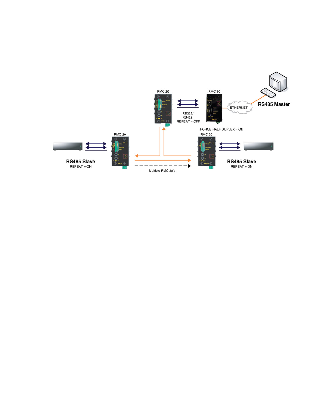
Serial Protocols
2.2.5 Force Half Duplex Mode of Operation
A “force half duplex” mode of operation allows use of extensions that create echo loops (as
optical loop topology that utilizes the RMC20 repeat mode function).
Figure 37: Optical loop topology
Figure 37 illustrates the optical loop topology that utilizes the RMC20 repeat mode function. The
repeat function will optically re-transmit any data received on the optical receiver, in addition to
any connected serial devices. As a result, any data transmitted from the master will be retransmitted optically to all the slaves.
This topology can be used for RS232, RS485, or RS422 multi-drop networks. In all cases, all
slaves have the repeat function (DIP position 4) ON, while the one connected to the RMC30 is
configured with the repeat function OFF. Used port on RMC30 must be in full duplex mode,
while parameter ForceHD (Force Half Duplex) parameter is turned ON.
ROS™ v3.5 66 RS400
Page 67

Serial Protocols
2.3 Serial Protocol Configuration and Statistics
The Serial Protocols menu is accessible from the main menu
Figure 38: Serial Protocols Menu
RS400 67 ROS™ v3.5
Page 68

Serial Protocols
2.3.1 Serial Ports
Figure 39: Serial Ports Table
Figure 40: Serial Ports Form
ROS™ v3.5 68 RS400
Page 69

Serial Protocols
Port
Synopsis: 1 to maximum port number
Default: 1
The port number as seen on the front plate silkscreen of the switch.
Name
Synopsis: Any 15 characters
Default: Port 1
A descriptive name that may be used to identify the device conected on that port.
Protocol
Synopsis: { None, RawSocket, ModbusServer, ModbusClient, DNP, WIN, TIN, MicroLok,
MirroredBits,PreemptRawSocket }
Default: None
The serial protocol supported on this serial port.
Type
Synopsis: { RS232, RS485, RS422, FIBER }
Default: RS232
A serial port interface type.
ForceHD
Synopsis: { On, Off }
Default: Off
Enables forcing half duplex mode of operation. While sending data out of the serial port all
received data are ignored. This mode of operation is available only on ports that operate in full
duplex mode.
Baud
Synopsis: 100 to 230400
Default: 9600
The baud rate at which to operate the port.
Data Bits
Synopsis: { 7, 8 }
Default: 8
The number of data bits to operate the port with.
Stop
Synopsis: { 1, 1.5, 2 }
Default: 1
The number of stop bits to operate the port with.
Parity
Synopsis: { None, Even, Odd }
Default: None
The parity to operate the port with.
Pack Timer
Synopsis: 5 to 1000
Default: 10 ms
The delay from the last received character until when data is forwarded.
Turnaround
Synopsis: 0 to 1000
RS400 69 ROS™ v3.5
Page 70

Serial Protocols
Default: 0 ms
The amount of delay (if any) to insert between the transmissions of individual messages out the
serial port.
DSCP
Synopsis: 0 to 63
Default: 0
DSCP - Differentiated Services Code Point, to set the DS byte in the IP header. DS byte setting
is supported in the egress direction only.
2.3.2 Raw Socket
Figure 41: Raw Socket Table
ROS™ v3.5 70 RS400
Page 71

Serial Protocols
Figure 42: Raw Socket Form
Port
Synopsis: 1 to maximum port number
Default: 1
The port number as seen on the front plate silkscreen of the switch.
Pack Char
Synopsis: 0 to 255 or { Off }
Default: Off
The character that can be used to force forwarding of accumulated data to the network. If a
packetization character is not configured, accumulated data will be forwarded based upon the
packetization timeout parameter.
Flow Control
Synopsis: { None, XON/XOFF }
Default: None
Whether to use XON-XOFF flow control on the port.
Transport
Synopsis: { TCP, UDP }
RS400 71 ROS™ v3.5
Page 72

Serial Protocols
Default: TCP
The network transport used to transport protocol data over IP network.
Call Dir
Synopsis: { In, Out, Both }
Default: In
Whether to accept an incoming connection, to place an outgoing connection, or to place
outgoing connection and wait for incoming (both directions). This parameter is applicable only
for TCP transport.
Max Conns
Synopsis: 1 to 64
Default: 1
The maximum number of allowed incoming TCP connections.
Loc Port
Synopsis: 1024 to 65535
Default: 50000
The local IP port to use when listening for an incoming connection or UDP data.
Rem Port
Synopsis: 1 to 65535
Default: 50000
The remote TCP port to use when placing an outgoing connection.
IP Address
Synopsis: ###.###.###.### where ### ranges from 0 to 255 or { }
Default:
For direction 'OUT' (client), remote IP address to use when placing an outgoing TCP connection
request.
For direction 'IN' (server), local interface IP address to listen to the local port for connection
request. Emtpy string can be used for IP address of management interface.
For direction 'BOTH' (client or server), remote IP address to use when placing an outgoing TCP
connection requestListening interface will be chosen by matching mask.
Link Stats
Synopsis: { Disabled, Enabled }
Default: Enabled
Enables links statistics collection for protocol.
ROS™ v3.5 72 RS400
Page 73

Serial Protocols
2.3.3 Preemptive Raw Socket
Figure 43: Preemptive Raw Socket Table
Figure 44: Preemptive Raw Socket Form
RS400 73 ROS™ v3.5
Page 74

Serial Protocols
Port
Synopsis: 1 to 4
Default: 1
The port number as seen on the front plate silkscreen of the switch.
Pack Char
Synopsis: 0 to 255 or { Off }
Default: Off
The character that can be used to force forwarding of accumulated data to the network. If a
packetization character is not configured, accumulated data will be forwarded based upon the
packetization timeout parameter.
Pack Timer
Synopsis: 3 to 1000
Default: 10 ms
The delay from the last received character until when data is forwarded.
Flow Control
Synopsis: { None, XON/XOFF }
Default: None
Whether to use XON-XOFF flowcontrol on the port.
Loc Port
Synopsis: 1024 to 65535
Default: 62001
The local IP port to use when listening for an incoming connection or UDP data.
Rem Port
Synopsis: 1 to 65535
Default: 62000
The remote TCP port to use when placing an outgoing connection.
IP Address
Synopsis: ###.###.###.### where ### ranges from 0 to 255 or { <EMTY STRING> }
Default:
The permanent master's IP address. Empty string represents management IP address of this
device.
Link Stats
Synopsis: { Disabled, Enabled }
Default: Enabled
Enables links statistics collection for protocol.
Dyn Pack Char
Synopsis: 0 to 255 or { Off }
Default: Off
The character that can be used to force forwarding of accumulated data to the network for
connection to dynamic master. If a packetization character is not configured, accumulated data
will be forwarded based upon the packetization timeout parameter.
Dyn Pack Timer
Synopsis: 3 to 1000
Default: 10 ms
The delay from the last received character until when data is forwarded to the dynamic master.
ROS™ v3.5 74 RS400
Page 75

Serial Protocols
Timeout
Synopsis: 10 to 3600
Default: 10 s
The time in seconds that is allowed to dynamic master to be idle before it's connection is closed.
The protocolo listens to the socket open to dymamic master, and if no data are received within
this time, conneciton will be closed.
2.3.4 Modbus Server
Figure 45: Modbus Server Table
Figure 46: Modbus Server Form
Port
Synopsis: 1 to maximum port number
RS400 75 ROS™ v3.5
Page 76

Serial Protocols
Default: 1
The port number as seen on the front plate silkscreen of the switch.
Response Timer
Synopsis: 50 to 10000
Default: 1000 ms
The maximum allowable time to wait for the RTU to start to respond.
Auxiliary TCP Port
Synopsis: 1024 to 65535 or { Disabled }
Default: Disabled
TCP Modbus Server always listens on TCP port 502. It may be additionally configured to listen
on this auxiliary port number, accepting calls on both.
Send Exceptions
Synopsis: { Disabled, Enabled }
Default: Enabled
This parameter enables/disables sending TCP Modbus exception back to the master if
response has not been received from the RTU within expected time.
Link Stats
Synopsis: { Disabled, Enabled }
Default: Enabled
Enables links statistics collection for protocol.
2.3.5 Modbus Client
Figure 47: Modbus Client Form
IP Port
Synopsis: 1 to 65535
Default: 502
A remote port number to which protocol sends TCP connection requests.
ROS™ v3.5 76 RS400
Page 77

Serial Protocols
Forward Exceptions
Synopsis: { Disabled, Enabled }
Default: Enabled
When the Master polls for an unconfigured RTU or the remote Modbus Server receives a poll
for an RTU which is not configured or is timing out, it returns an exception message. Enabling
this feature forwards these messages to the Master as exception codes 10 (no path) and 11 (no
response). Disable this feature if your Master is confused by these codes and would prefer to
time-out when a failure occurs.
Link Stats
Synopsis: { Disabled, Enabled }
Default: Enabled
Enables links statistics collection for protocol.
DSCP
Synopsis: 0 to 63
Default: 0
DSCP - Differentiated Services Code Point, to set the DS byte in the IP header. DS byte setting
is supported in the egress direction only.
2.3.6 WIN and TIN
Figure 48: WIN and TIN Form
RS400 77 ROS™ v3.5
Page 78

Serial Protocols
TIN Mode:
Synopsis: 1 to 2
Default: 1
TIN Protocol running mode.
TIN Transport:
Synopsis: { TCP, UDP }
Default: UDP
The network transport used to transport protocol data over IP network.
WIN Transport:
Synopsis: { TCP, UDP }
Default: UDP
The network transport used to transport protocol data over IP network.
TIN IP Port
Synopsis: 1024 to 65535
Default: 51000
The local port number on which TIN protocol listens for TCP connections or UDP datagrams.
WIN IP Port
Synopsis: 1024 to 65535
Default: 52000
The local port number on which WIN protocol listens for TCP connections or UDP datagrams.
Message Aging Timer
Synopsis: 1 to 3600 or { Disabled }
Default: Disabled
This timing parameter (in seconds) is used to configure the removal of duplicate messages in
TIN mode2. If the same message is received within the time interval specified by this parameter,
the new message is considered duplicate, and is thus discarded.
Address Aging Timer
Synopsis: 60 to 1000
Default: 300 s
The time of communication inactivity after which a learned TIN address is removed from the
device address table. Entries in Link Statistics Table with the aged address will be kept until
statistics are cleared.
Broadcast Addresses
Synopsis: { Static, Dynamic, StaticAndDynamic }
Default: Static
A The device address table in which addresses will be found for broadcast messages.
Unicast Addresses
Synopsis: { Static, Dynamic, StaticAndDynamic }
Default: Dynamic
A The device address table in which addresses will be found for unicast messages.
Link Stats
Synopsis: { Disabled, Enabled }
Default: Enabled
Enables links statistics collection for protocol.
ROS™ v3.5 78 RS400
Page 79

Serial Protocols
WIN DSCP
Synopsis: 0 to 63
Default: 0
DSCP - Differentiated Services Code Point, to set the DS byte in the IP header. DS byte setting
is supported in the egress direction only.
TIN DSCP
Synopsis: 0 to 63
Default: 0
DSCP - Differentiated Services Code Point, to set the DS byte in the IP header. DS byte setting
is supported in the egress direction only.
2.3.7 MicroLok
Figure 49: MicroLok Form
Transport
Synopsis: { TCP, UDP }
Default: UDP
The network transport used to transport protocol data over IP network.
IP Port
Synopsis: 1024 to 65535
Default: 60000
A local port number on which protocol listens for UDP datagrams.
Link Stats
Synopsis: { Disabled, Enabled }
Default: Enabled
Enables links statistics collection for protocol.
DSCP
Synopsis: 0 to 63
RS400 79 ROS™ v3.5
Page 80

Serial Protocols
Default: 0
DSCP - Differentiated Services Code Point, to set the DS byte in the IP header. DS byte setting
is supported in the egress direction only.
2.3.8 DNP
Figure 50: DNP Form
Transport
Synopsis: { TCP, UDP }
Default: TCP
The network transport used to transport protocol data over IP network.
IP Port
Synopsis: 1024 to 65535
Default: 20000
A local port number on which protocol listens for UDP datagrams.
Learning
Synopsis: ###.###.###.### where ### ranges from 0 to 255 or { Disabled }
Default: Disabled
Enable or disable address learning. Learning can be disabled, or enabled on management IP
interface (empty string), or enabled on the interface with specific IP address.
If learning is enabled and remote address is not known, UDP broadcast message will be sent
and source addresses will be learned on devices that run DNP protocol. If local address is not
known, message will be sent to all serial ports running DNP protocol. Local addresses will be
learned from local responses. If TCP transport is configured, connection will be established to
the devices with the corresponding IP address.
ROS™ v3.5 80 RS400
Page 81

Serial Protocols
Aging Timer
Synopsis: 60 to 1000
Default: 300 s
The time of communication inactivity after which a learned DNP address is removed from the
device address table. Entries in Link Statistics Table with the aged address will be kept until
statistics is cleared.
Link Stats
Synopsis: { Disabled, Enabled }
Default: Enabled
Enables links statistics collection for protocol.
DSCP
Synopsis: 0 to 63
Default: 0
DSCP - Differentiated Services Code Point, to set the DS byte in the IP header. DS byte setting
is supported in the egress direction only.
2.3.9 Mirrored Bits
Figure 51: Mirrored Bits Table
RS400 81 ROS™ v3.5
Page 82
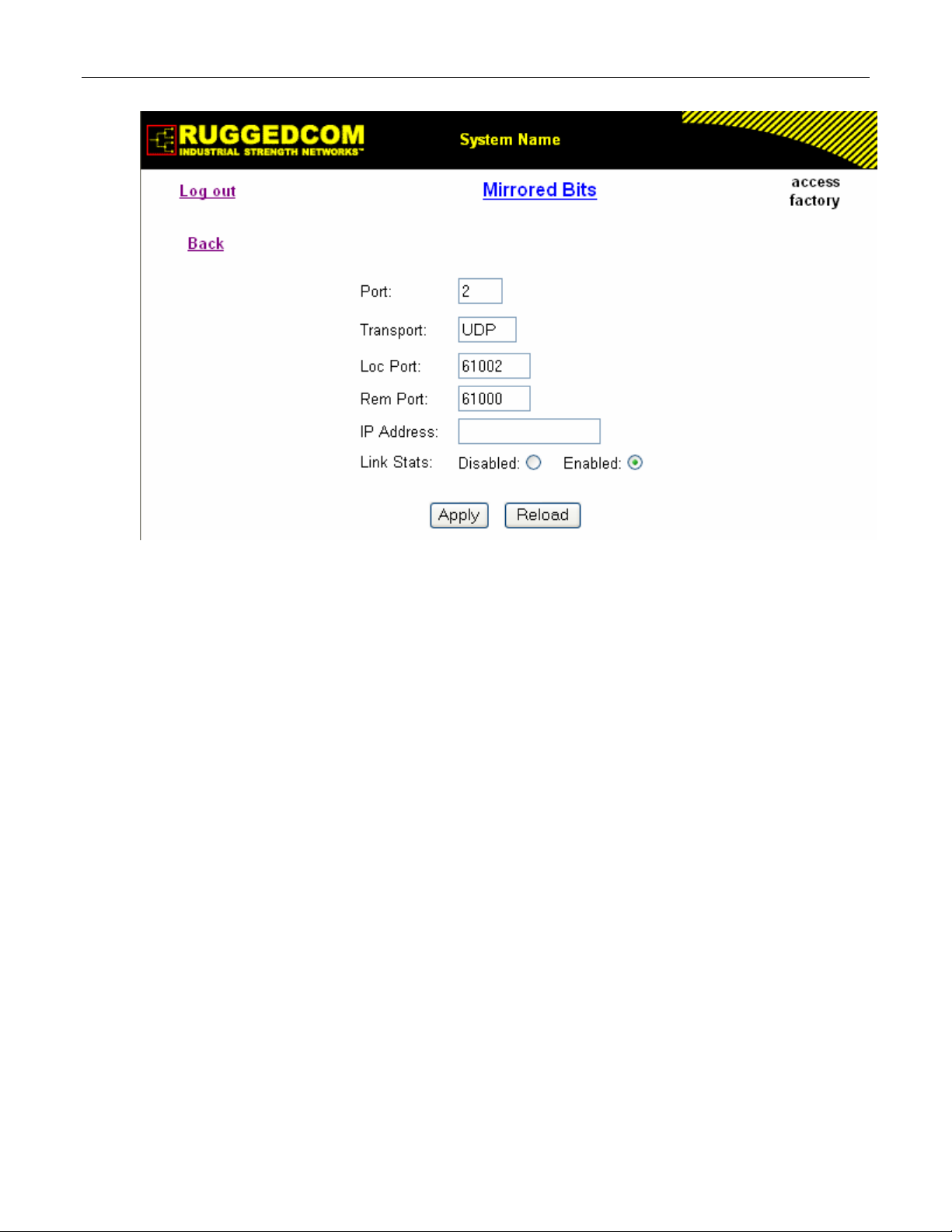
Serial Protocols
Figure 52: Mirrored Bits Form
Port
Synopsis: 1 to 4
Default: 1
The port number as seen on the front plate silkscreen of the switch.
Transport
Synopsis: { TCP, UDP }
Default: UDP
The network transport used to transport protocol data over IP network.
Loc Port
Synopsis: 1024 to 65535
Default: 61001
The local IP port to use when listening for an incoming connection or UDP data.
Rem Port
Synopsis: 1 to 65535
Default: 61000
The remote TCP port to use when placing an outgoing connection.
IP Address
Synopsis: ###.###.###.### where ### ranges from 0 to 255 or { <EMTY STRING> }
Default:
For outgoing TCP connection (client) and UDP transport this is the remote IP address to
communicate with.
For incoming TCP connection (server), this is the local interface IP address to listen to the local
port for connection request. If empti string is configured, IP address of management interface is
used.
ROS™ v3.5 82 RS400
Page 83

Serial Protocols
For both, outgoing and incoming connections enabled (client or server), this is remote IP
address where to place an outgoing TCP connection request or from which to accept calls.
Link Stats
Synopsis: { Disabled, Enabled }
Default: Enabled
Enables links statistics collection for protocol.
2.3.10 Device Addresses
Up to 1024 entries can be created in this table.
Figure 53: Device Address Table
RS400 83 ROS™ v3.5
Page 84

Serial Protocols
Figure 54: Device Address Form
Protocol
Synopsis: { ModbusServer, ModbusClient, DNP, WIN, TIN, MicroLok }
Default: ModbusServer
The serial protocol supported on this serial port.
Address
Synopsis: Any 31 characters
Default:
The destination (source) device address. Could be local or remote. Local address is the address
of the device connected to the serial port on this device, and serial port must be configured.
Remote address is the address of the device connected to the remote host's serial port. In that
case RemoteIpAddr must be configured. NOTE: The range and format of the address is defined
by protocol:
Modbus: 1 to 244
MicroLok: 1 to 65535, or 8 to hexadecimal digits ‘1’ to ‘a’
DNP 3.0: 1 to 65520
WIN: 6 bits address (0 to 63)
TIN: String 'wdr' for wayside data radio (TIN mode 2), or 32 bits address, 8 digits, allowed are
hexadecimal digits '0' to 'f'. All zeros are not allowed.
Remote IP Addr
Synopsis: ###.###.###.### where ### ranges from 0 to 255
Default:
The IP address of remote host where device with configured remote address is connected.
Port
Synopsis: 1 to maximum port number or {Unknown}
ROS™ v3.5 84 RS400
Page 85

Serial Protocols
Default: Unknown
The serial port to which device is attached. If the device with this address is attached to the
serial port of remote host, the value of this parameter is 'Unknown'.
Name
Synopsis: Any 16 characters
Default:
The addressed device name.
2.3.11 Dynamic Device Addresses
This table provides ability to view TIN protocol’s device addresses from remote locations that
were learned dynamically.
Figure 55: Dynamic Device Address Table
Figure 56: Dynamic Device Address Form
RS400 85 ROS™ v3.5
Page 86

Serial Protocols
Protocol
Synopsis: { TIN }
The serial protocol supported on this serial port.
Address
Synopsis: Any 31 characters
The remote device address.
Location
Synopsis: ###.###.###.### where ### ranges from 0 to 255
The IP Address of the remote host.
IP Port
Synopsis: 1 to 65535
The remote port number through which remote device sent a UDP datagram or TCP connection
is established.
RSSI
Synopsis: -128 to 0 or { N/A }
The signal strength indicator received from wayside data radio. N/A for TIN Mode 1.
Aging Time
Synopsis: 0 to 1000
The amount of time since the last packet arrived from the device. Once this time exceeds the
Aging Timer setting for protocol, the device will be removed from the table. This value is
updated every 10 seconds.
2.3.12 Links Statistics
This table presents detailed statistics for a specific link between two devices.
Figure 57: Links Statistics Table
ROS™ v3.5 86 RS400
Page 87

Serial Protocols
Figure 58: Links Statistics Form
Protocol
Synopsis: { None, RawSocket, ModbusServer, ModbusClient, DNP, WIN, TIN, MicroLok }
The serial protocol supported by devices that create this link.
Local Address
Synopsis: Any 27 characters
The address of the device connected to the serial port on this device.
Remote Address
Synopsis: Any 35 characters
The address of the device connected to the remote host's serial port.
Rx Local
Synopsis: 0 to 4294967295
The number of packets received from the local address that were forwarded to the remote side.
Rx Remote
Synopsis: 0 to 4294967295
The number of packets received from the local address that were forwarded to the local serial
port.
Erroneous
Synopsis: 0 to 4294967295
The number of erroneous packets received from remote address.
2.3.13 Connection Statistics
This table presents statistics for all active TCP connections on serial protocols. The statistics
are updated once every second.
RS400 87 ROS™ v3.5
Page 88

Serial Protocols
Figure 59: Connection Statistics Table
Remote IP
Synopsis: ###.###.###.### where ### ranges from 0 to 255
The remote IP address of the connection.
Remote Port
Synopsis: 0 to 65535
The remote port number of the connection.
Local Port
Synopsis: 0 to 65535
The local port number of the connection.
Rx Packets
Synopsis: 0 to 4294967295
The number of received packets on the connection.
Tx Packets
Synopsis: 0 to 4294967295
The number of packets transmitted on the connection.
2.3.14 Serial Port Statistics
ROS™ v3.5 88 RS400
Page 89

Serial Protocols
Figure 60: Serial Port Statistics Table
Port
Synopsis: 1 to maximum port number
The port number as seen on the front plate silkscreen of the switch.
Protocol
Synopsis: Any 15 characters
The serial protocol supported on this serial port.
Rx Chars
Synopsis: 0 to 4294967295
The number of received characters.
Tx Chars
Synopsis: 0 to 4294967295
The number of transmitted characters.
Rx Packets
Synopsis: 0 to 4294967295
The number of received packets.
Tx Packets
Synopsis: 0 to 4294967295
The number of transmitted packets.
Packet Errors
Synopsis: 0 to 4294967295
The number of packets received from this port and discarded (error in protocol, crc or routing
information not found).
Parity Errors
Synopsis: 0 to 4294967295
The number of Parity Errors
Framing Errors
Synopsis: 0 to 4294967295
The number of Framing Errors
Overrun Errors
Synopsis: 0 to 4294967295
The number of Overrun Errors
RS400 89 ROS™ v3.5
Page 90

Serial Protocols
2.3.15 Clearing Serial Port Statistics
This command clears serial ports statistics and links statistics.
Figure 61: Clear Serial Port Statistics Form
This command clears statistics on one or more serial ports. Ports to clear statistics will be
chosen checking out required boxes.
2.3.16 Resetting Serial Ports
Figure 62: Reset Serial Port(s) Form
Ports to reset will be chosen checking out required boxes.
ROS™ v3.5 90 RS400
Page 91

Serial Protocols
2.4 Troubleshooting
Problem One
I configured a Serial IP to use TCP transport ( in or out connection request direction) but
nothing seems to be happening. What is going on?
Ensure that an Ethernet port link is up.
The peer may not be requesting (accepting) connections. The Connection Statistics Table will
display whether the connection is active or not.
The peer may not be sending data. The Connection statistics Table will display the counts of
transmitted and received data packets via IP network.
Watch the connection activity. For a detailed description of the TCP connection activity, turn on
tracing at the TRANSPORT level.
Problem Two
My connections (as shown in the Connection Statistics Table) go up and then
immediately go down again. What is going on?
If two ports (on the same or different RuggedServers™) are configured to call the same IP/TCP
port in the network, only the first one to call will be successful. All other ports will fail, displaying
the attempts as brief periods of connection in the Connection Statistics Table.
Problem Three
My Modbus polling is not working. I am sure that a connection is occurring but my
Master reports an error connecting to the device. What is happening?
Are framing, parity or overrun errors reported at either the client or server?
Is the Server Gateway set up for the correct baud, parity and stop bits? Is the RTU online?
Is an adequate response timer configured at the server? Is the Master’s time-out long enough?
Is the Master pausing in the middle of transmitting the request? Some versions of the Windows
OS have been observed to display this behavior as load is increased.
Could the IP network be splitting the Modbus message into two TCP segments?
Ultimately, it may be necessary to view the contents of messages transmitted over TCP (by
activating tracing at the IP level) or by viewing messages at the serial port level (See the section
on tracing at the SERIAL level.) Start by tracing at the client, ensuring that it is receiving and
forwarding the request over IP. Then, if needs be, trace at the server to ensure that it is
receiving the request and forwarding to the RTU. Verify that the RTU is responding properly.
Problem Four
How do I get figures (like those presented earlier in the chapter) for my own analysis?
Activating tracing at the IP level and serial port level. The trace package displays timestamps,
packet sizes, message directions and timeout events occurrences.
RS400 91 ROS™ v3.5
Page 92

Page 93

Ethernet Ports
3 Ethernet Ports
ROS™ Ethernet port control provides you with the following features:
• Configuring port physical parameters
• Configuring link alarms/traps for the port
• Configuring port rate limiting
• Using Port Mirroring
• Viewing the status of ports
• Resetting all or some ports
• Using Link-Fault-Indication (LFI)
3.1 Controller Protection Through Link-Fault-Indication (LFI)
Modern industrial controllers often feature backup Ethernet ports used in the event of a link
failure. When these interfaces are supported by media (such as fiber) that employ separate
transmit and receive paths, the interface can be vulnerable to failures that occur in only one of
the two paths.
Refer to the following figure. While the link between switch A and the controller functions
normally, the controller holds the backup link down. Switch B learns that it must forward frames
towards switch A in order to reach the controller.
Unfortunately, if the transmission path from the controller to switch A fails, switch A will still
generate link signals to the controller. The controller will still detect link to switch A and will not
failover to the backup port.
Figure 63: Controller Protection Through LFI
To overcome this problem, there should be a way of notifying the link partner in case a link
integrity signal stopped being received from it. Such a way natively exists in some link media but
not in others.
RS400 93 ROS™ v3.5
Page 94

Ethernet Ports
1. Auto-Negotiating links (100Base-TX,1000Base-T,1000Base-X) - auto-negotiation built-in
feature (a special flag called Remote Fault Indication is set in the transmitted autonegotiation signal)
2. 100Base-FX links - Far–End-Fault-Indication (FEFI) is a standard feature defined by the
IEEE 802.3 standard for this link type. The feature includes:
a. Transmitting FEFI - transmitting modified link integrity signal in case a link failure is
detected, i.e. no link signal is received from the link partner
b. Detecting FEFI - indicating link loss in case FEFI signal is received from the link
partner.
3. 10Base-FL links - no standard support
As one can see from the above, 10Base-FL links have no native link partner notification
mechanism. Also, FEFI support in 100Base-FX links is optional according to the IEEE 802.3
standard which means some link partners may not support it.
RuggedCom offers an advanced Link-Fault-Indication (LFI) feature for the links where no native
link partner notification mechanism is available. With the LFI enabled, the device bases
generation of a link integrity signal upon its reception of a link signal. In the diagram above, if
switch A fails to receive a link signal from the controller it will stop generating a link signal. The
controller will detect the link failure and switch to the backup port.
The switch can also be configured to flush the MAC address table for the controller port (see
MAC Address Tables section). Frames destined for the controller will be flooded to switch B
where they will be forwarded to the controller (after the controller transmits its first frame).
Note: If both link partners are capable of the LFI, it MUST NOT be enabled on both sides of the link. If it
is enabled on both sides, the link will never be established because each side will permanently wait
for its partner to transmit a link signal.
ROS™ v3.5 94 RS400
Page 95

Ethernet Ports
3.2 Ethernet Ports Configuration and Status
The Ethernet Ports menu is accessible from the main menu.
Figure 64: Ethernet Ports Menu
RS400 95 ROS™ v3.5
Page 96

Ethernet Ports
3.2.1 Port Parameters
Figure 65: Port Parameters Table
Figure 66: Port Parameters Form
ROS™ v3.5 96 RS400
Page 97

Ethernet Ports
Port
Synopsis: 1 to maximum port number
Default: 0
The port number as seen on the front plate silkscreen of the switch.
Name
Synopsis: Any 15 characters
Default: Not installed
A descriptive name that may be used to identify the device conected on that port.
Media
Synopsis: { 100TX, 10FL, 100FX, 1000X, 1000T }
The type of the port media.
State
Synopsis: { Disabled, Enabled }
Default: Enabled
Disabling a port will prevent all frames from being sent and received on that port. Also, when
disabled link integrity pulses are not sent so that the link/activity LED will never be lit. You may
want to disable a port for troubleshooting or to secure it from unauthorized connections.
AutoN
Synopsis: { Off, On }
Default: On
Enable or disable IEEE 802.3 auto-negotiation. Enabling auto-negotiation results in speed and
duplex being negotiated upon link detection; both end devices must be auto-negotiation
compliant for the best possible results. 10Mbps and 100Mbps fiber optic media do not support
auto-negotiation so these media must be explicitly configured to either half or full duplex. Full
duplex operation requires that both ends are configured as such or else severe frame loss will
occur during heavy network traffic
Speed
Synopsis: { Auto, 10M, 100M, 1G }
Default: Auto
Speed (in Megabit-per-second or Gigabit-per-second). If auto-negotiation is enabled, this is the
speed capability advertised by the auto-negotiation process. If auto-negotiation is disabled, the
port is explicitly forced to this speed mode.
AUTO means advertise all supported speed modes.
Dupx
Synopsis: { Auto, Half, Full }
Default: Auto
Duplex mode. If auto-negotiation is enabled, this is the duplex capability advertised by the autonegotiation process. If auto-negotiation is disabled, the port is explicitly forced to this duplex
mode.
AUTO means advertise all supported duplex modes.
Flow Control
Synopsis: { Off, On }
Default: Off
Flow Control is useful for preventing frame loss during times of severe network traffic. Examples
of this include multiple source ports sending to a single destination port or a higher speed port
bursting to a lower speed port.
RS400 97 ROS™ v3.5
Page 98

Ethernet Ports
When the port is half-duplex it is accomplished using 'backpressure' where the switch simulates
collisions causing the sending device to retry transmissions according to the Ethernet backoff
algorithm. When the port is full-duplex it is accomplished using PAUSE frames which causes
the sending device to stop transmitting for a certain period of time.
LFI
Synopsis: { Off, On }
Default: Off
Enabling Link-Fault-Indication (LFI) inhibits transmitting link integrity signal when the receive link
has failed. This allows the device at far end to detect link failure under all circumstances.
NOTE: this feature must not be enabled at both ends of a link.
Link Alarms
Synopsis: { Off, On }
Default: On
Disabling link state alarms will prevent alarms and LinkUp and LinkDown SNMP traps from
being sent for that port.
Note If one end of the link is fixed to a specific speed and duplex type and the peer auto-negotiates,
there is a strong possibility that the link will either fail to raise, or raise with the wrong settings on
the auto-negotiating side. The auto-negotiating peer will fall back to half-duplex operation, even
when the fixed side is full duplex. Full duplex operation requires that both ends are configured as
such or else severe frame loss will occur during heavy network traffic. At lower traffic volumes the
link may display few if any errors As the traffic volume rises the fixed negotiation side will begin to
experience dropped packets while the auto-negotiating side will experience excessive collisions.
Ultimately, as traffic load approaches 100% the link will become entirely unusable. These problems
can be avoided by always configuring ports to the appropriate fixed values.
ROS™ v3.5 98 RS400
Page 99

Ethernet Ports
3.2.2 Port Rate Limiting
Figure 67: Port Rate Limiting Table
Figure 68: Port Rate Limiting Form
Port
Synopsis: 1 to maximum port number
RS400 99 ROS™ v3.5
Page 100

Ethernet Ports
Default: 1
The port number as seen on the front plate silkscreen of the switch.
Ingress Limit
Synopsis: { Disabled, 128 Kbps, 256 Kbps, 512 Kbps, 1 Mbps, 2 Mbps, 4 Mbps, 8 Mbps }
Default: 1 Mbps
The rate at which received frames (of the type described by the ingress frames parameter) will
start to be discarded by the switch.
Ingress Frames
Synopsis: { Broadcast, Multicast, All }
Default: Broadcast
This parameter specifies the types of frames to rate-limit on this port. It applies only to received
frames:
BROADCAST - only broadcast frames will be limited
MULTICAST - all multicast frames (including broadcast) will be limited
ALL - all frames (both multicast and unicast) will be limited
Egress Limit
Synopsis: 62 to 256000 Kbps or { Disabled }
Default: Disabled
The maximum rate at which the switch will transmit (multicast, broadcast and unicast) frames on
this port. The switch will discard frames in order to meet this rate if required.
3.2.3 Port Mirroring
Port mirroring is a troubleshooting tool in which all traffic on a designated port is copied (or
mirrored) to a target port. If a protocol analyzer is attached to the target port, the traffic stream of
valid frames on any source port is made available for analysis.
Select a target port that has a higher speed than the source port. Mirroring a 100 Mbps port
onto a 10 Mbps port may result in an improperly mirrored stream.
Frames will be dropped if the full duplex rate of frames on the source port exceeds the
transmission speed of the target port. Since both transmitted and received frames on the source
port are mirrored to the target port, frames will be discarded if the sum traffic exceeds the target
port’s transmission rate. This problem reaches its extreme in the case where traffic on a 100
Mbps full duplex port is mirrored onto a 10 Mbps half duplex port.
Note: Invalid frames received on the source port will not be mirrored. These include CRC errors, oversize
and undersize packets, fragments, jabbers, collisions, late collisions and dropped events).
Port Mirroring Limitations
• Traffic will be mirrored onto the target port only if the target port is a member of the same
VLANs as the source port.
• The target port may sometimes incorrectly show the VLAN tagged/untagged format of the
mirrored frames.
• Network management frames (such as RSTP, GVRP etc. ) may not be mirrored.
• Switch management frames generated by the switch (such as Telnet, HTTP, SNMP etc.)
may not be mirrored.
ROS™ v3.5 100 RS400
 Loading...