

Page 1

Rugged Operating System
(ROS®) v3.11 User Guide
For use with :
RMC30
July 19, 2012
www.RuggedCom.com
Page 2

Rugged Operating System
Rugged Operating System: (ROS®) v3.11 User Guide
Copyright © 2012 RuggedCom Inc.
ALL RIGHTS RESERVED
Dissemination or reproduction of this document, or evaluation and communication of its contents, is not authorized except where
expressly permitted. Violations are liable for damages. All rights reserved, particularly for the purposes of patent application or
trademark registration.
This document contains proprietary information, which is protected by copyright. All rights are reserved. No part of this document may
be photocopied, reproduced or translated to another language without the prior written consent of RuggedCom Inc.
Disclaimer Of Liability
We have checked the contents of this manual against the hardware and software described. However, deviations from the description
cannot be completely ruled out.
RuggedCom shall not be liable for any errors or omissions contained herein or for consequential damages in connection with the
furnishing, performance, or use of this material.
The information given in this document is reviewed regularly and any necessary corrections will be included in subsequent editions.
We appreciate any suggested improvements. We reserve the right to make technical improvements without notice.
Registered Trademarks
RuggedServer™, RuggedWireless™, RuggedCom Discovery Protocol™ (RCDP™), RuggedExplorer™, Enhanced Rapid Spanning
Tree Protocol™ (eRSTP™), are trademarks of RuggedCom Inc. Rugged Operating System® (ROS®) and RuggedSwitch® are
registered trademarks of RuggedCom Inc. Other designations in this manual might be trademarks whose use by third parties for their
own purposes would infringe the rights of the owner.
Warranty
Five (5) years from date of purchase, return to factory. For warranty details, visit www.ruggedcom.com or contact your customer
service representative.
Contacting RuggedCom
Corporate Headquarters US Headquarters Europe Headquarters
RuggedCom Inc.
300 Applewood Crescent
Concord, Ontario
Canada, L4K 5C7
Tel: +1 905 856 5288
Fax: +1 905 856 1995
Toll-free: 1 888 264 0006
Technical Support
Toll Free (North America): 1 866 922 7975
International: +1 905 856 5288
Email: Support@RuggedCom.com
Web: www.RuggedCom.com
RuggedCom
1930 Harrison St., Suite 209
Hollywood, Florida
USA, 33020
Tel: +1 954 922 7938 ext. 103
Fax: +1 954 922 7984
Toll-free: 1 888 264 0006
Email: RuggedSales@RuggedCom.com
RuggedCom
Unit 41, Aztec Centre,
Aztec West, Almondsbury, Bristol
United Kingdom BS32 4TD
Tel: +44 1454 203 404
Fax: +44 1454 203 403
Page 3

Rugged Operating System
Table of Contents
Preface ................................................................................................................................. 9
Supported Platforms ..................................................................................................... 9
Who Should Use This User Guide ............................................................................... 9
How Chapters are organized ....................................................................................... 9
Document Conventions ................................................................................................ 9
Applicable Firmware Revision .................................................................................... 10
Firmware/User Guide Version Numbering System ..................................................... 10
1. Administration ................................................................................................................. 11
1.1. The ROS® User Interface ................................................................................... 11
1.1.1. Using the RS232 Port to Access the User Interface ................................ 11
1.1.2. The Structure of the User Interface .......................................................... 11
1.1.3. Making Configuration Changes ................................................................ 12
1.1.4. Updates Occur In Real Time .................................................................... 13
1.1.5. Alarm Indications Are Provided ................................................................ 13
1.1.6. The CLI Shell ........................................................................................... 13
1.2. The ROS® Secure Shell Server ......................................................................... 13
1.2.1. Using a Secure Shell to Access the User Interface .................................. 13
1.2.2. Using a Secure Shell to Transfer Files ..................................................... 13
1.3. The ROS® Web Server Interface ....................................................................... 14
1.3.1. Using a Web Browser to Access the Web Interface ................................. 14
1.3.2. Customizing the Login Page .................................................................... 15
1.3.3. The Structure of the Web Interface .......................................................... 15
1.3.4. Making Configuration Changes ................................................................ 16
1.3.5. Updating Statistics Displays ..................................................................... 16
1.4. Security Recommendations ................................................................................. 16
1.5. Administration Menu ............................................................................................ 16
1.6. IP Interfaces ........................................................................................................ 17
1.7. IP Gateways ........................................................................................................ 18
1.8. IP Services .......................................................................................................... 19
1.9. System Identification ........................................................................................... 21
1.10. Passwords ......................................................................................................... 22
1.11. System Time Management ............................................................................... 24
1.11.1. Configuring System Time ....................................................................... 24
1.11.1.1. Configuring Time and Date .......................................................... 25
1.11.1.2. Configuring NTP Service ............................................................. 27
1.12. SNMP Management .......................................................................................... 28
1.12.1. SNMP Users ........................................................................................... 28
1.12.2. SNMP Security to Group Maps .............................................................. 30
1.12.3. SNMP Access ......................................................................................... 31
1.13. RADIUS ............................................................................................................. 33
1.13.1. RADIUS overview ................................................................................... 33
1.13.2. User Login Authentication and Authorization .......................................... 33
1.13.3. Radius Server Configuration .................................................................. 35
1.14. TACACS+ .......................................................................................................... 36
1.14.1. User Login Authentication and Authorization .......................................... 36
1.14.2. TACACS+ Server Configuration ............................................................. 37
ROS® v3.11User Guide 3 RMC30
Page 4

Rugged Operating System
1.14.3. User Privilge Level Configuartion ........................................................... 38
1.14.4. TACACS+ Server Privilege Configuration .............................................. 38
1.15. Syslog ................................................................................................................ 39
1.15.1. Configuring Local Syslog ........................................................................ 39
1.15.2. Configuring Remote Syslog Client .......................................................... 40
1.15.3. Configuring the Remote Syslog Server .................................................. 41
1.16. Troubleshooting ................................................................................................. 42
2. Serial Protocols .............................................................................................................. 43
2.1. Serial Protocols Overview ................................................................................... 43
2.1.1. Raw Socket protocol features .................................................................. 43
2.1.2. DNP over Raw Socket protocol features .................................................. 43
2.1.3. Preemptive Raw Socket protocol features ............................................... 44
2.1.4. Modbus protocol features ......................................................................... 44
2.1.5. DNP protocol features .............................................................................. 44
2.1.6. Microlok protocol features ........................................................................ 44
2.1.7. WIN protocol features ............................................................................... 44
2.1.8. TIN protocol features ................................................................................ 44
2.1.9. TelnetComPort protocol features .............................................................. 44
2.2. Serial Protocols Operation .................................................................................. 45
2.2.1. Serial Encapsulation Applications ............................................................. 45
2.2.1.1. Character Encapsulation (Raw Socket) ......................................... 45
2.2.1.2. RTU Polling ................................................................................... 45
2.2.1.3. Broadcast RTU Polling .................................................................. 46
2.2.1.4. Preemptive Raw Socket ................................................................ 47
2.2.1.5. Use of Port Redirectors ................................................................. 48
2.2.1.6. Message Packetization .................................................................. 48
2.2.2. Modbus Server and Client Applications .................................................... 49
2.2.2.1. TCPModbus Performance Determinants ....................................... 49
2.2.2.2. A Worked Example ........................................................................ 51
2.2.2.3. Use of Turnaround Delay .............................................................. 51
2.2.3. DNP 3.0, Microlok, TIN and WIN Applications ......................................... 51
2.2.3.1. The Concept of Links .................................................................... 52
2.2.3.2. Address Learning ........................................................................... 52
2.2.3.2.1. Address Learning for TIN .................................................... 52
2.2.3.2.2. Address Learning for DNP .................................................. 53
2.2.3.2.3. Broadcast Messages ........................................................... 54
2.2.3.3. Transport Protocols ........................................................................ 54
2.2.3.3.1. Transport for Raw Socket ................................................... 54
2.2.3.3.2. Transport for Protocols with Defined Links .......................... 55
2.2.3.3.3. Use of Differentiated Services Code Point (DSCP) ............. 55
2.2.4. Force Half-Duplex Mode of Operation ...................................................... 55
2.3. Serial Protocol Configuration ............................................................................... 56
2.3.1. Serial Ports ............................................................................................... 57
2.3.2. Raw Socket .............................................................................................. 59
2.3.3. Remote Hosts ........................................................................................... 62
2.3.4. Preemptive Raw Socket ........................................................................... 63
2.3.5. Modbus Server ......................................................................................... 65
2.3.6. Modbus Client ........................................................................................... 66
2.3.7. WIN and TIN ............................................................................................ 67
ROS® v3.11User Guide 4 RMC30
Page 5

Rugged Operating System
2.3.8. MicroLok ................................................................................................... 69
2.3.9. DNP .......................................................................................................... 70
2.3.10. DNP over Raw Socket ........................................................................... 71
2.3.11. Mirrored Bits ........................................................................................... 73
2.3.12. TelnetComPort ........................................................................................ 75
2.3.13. Device Addresses ................................................................................... 77
2.3.14. Dynamic Device Addresses .................................................................... 78
2.4. Serial Statistics .................................................................................................... 80
2.4.1. Link Statistics ........................................................................................... 80
2.4.2. Connection Statistics ................................................................................ 81
2.4.3. Serial Port Statistics ................................................................................. 82
2.4.4. Clearing Serial Port Statistics ................................................................... 83
2.4.5. Resetting Serial Ports ............................................................................... 84
2.5. Troubleshooting ................................................................................................... 84
3. Network Discovery ......................................................................................................... 86
3.1. RCDP Operation ................................................................................................. 86
3.2. Network Discovery Menu .................................................................................... 86
3.2.1. RCDP Configuration ................................................................................. 87
4. Diagnostics ..................................................................................................................... 88
4.1. Using the Alarm System ..................................................................................... 88
4.1.1. Active Alarms ............................................................................................ 88
4.1.2. Passive Alarms ......................................................................................... 89
4.1.3. Alarms and the Critical Failure Relay ....................................................... 89
4.1.4. Configuring Alarms ................................................................................... 89
4.1.5. Viewing and Clearing Alarms ................................................................... 91
4.2. Viewing CPU Diagnostics ................................................................................... 92
4.3. Viewing and Clearing the System Log ................................................................ 93
4.4. Viewing Product Information ............................................................................... 94
4.5. Loading Factory Default Configuration ................................................................ 95
4.6. Resetting the Device ........................................................................................... 96
4.7. Transferring Files ................................................................................................ 97
5. Using the CLI Shell ........................................................................................................ 98
5.1. Summary Of CLI Commands available in ROS® ................................................ 98
5.2. Obtaining Help For A Command ......................................................................... 98
5.3. Viewing Files ....................................................................................................... 98
5.3.1. Listing Files .............................................................................................. 99
5.3.2. Viewing and Clearing Log Files ................................................................ 99
5.4. Managing The Flash Filesystem ....................................................................... 100
5.4.1. Flash Filesystem Memory Mapping ........................................................ 100
5.4.2. Obtaining Information On A Particular File ............................................. 100
5.4.3. Defragmenting The Flash Filesystem ..................................................... 101
5.5. Pinging a Remote Device ................................................................................. 101
5.6. Tracing Events .................................................................................................. 102
5.6.1. Enabling Trace ....................................................................................... 102
5.6.2. Starting Trace ......................................................................................... 103
5.7. Viewing DHCP Learned Information ................................................................. 104
5.8. Executing Commands Remotely Through RSH ................................................ 104
5.9. Resetting the Device ......................................................................................... 104
6. Firmware Upgrade and Configuration Management .................................................... 105
ROS® v3.11User Guide 5 RMC30
Page 6

Rugged Operating System
6.1. Files Of Interest ................................................................................................. 105
6.2. File Transfer Mechanisms ................................................................................. 105
6.3. Console Sessions .............................................................................................. 105
6.4. Upgrading Firmware .......................................................................................... 105
6.4.1. Applying the Upgrade ............................................................................. 106
6.4.2. Security Considerations .......................................................................... 106
6.4.3. Upgrading Firmware Using XModem ...................................................... 106
6.4.4. Upgrading Firmware Using the ROS® TFTP Server .............................. 107
6.4.5. Upgrading Firmware Using the ROS® TFTP Client ............................... 107
6.4.6. Upgrading Firmware Using SFTP ........................................................... 108
6.5. Updating Configuration ...................................................................................... 108
6.6. Backing Up ROS®System Files ........................................................................ 109
6.6.1. Backing Up Files Using SFTP ................................................................ 110
6.7. Using SQL Commands ..................................................................................... 110
6.7.1. Getting Started ....................................................................................... 110
6.7.2. Finding the Correct Table ....................................................................... 110
6.7.3. Retrieving Information ............................................................................. 111
6.7.4. Changing Values in a Table ................................................................... 112
6.7.5. Setting Default Values in a Table ........................................................... 112
6.7.6. Using RSH and SQL .............................................................................. 112
A. SNMP MIB Support ..................................................................................................... 114
A.1. Standard MIBs .................................................................................................. 114
A.2. RuggedCom proprietary MIBs .......................................................................... 115
A.3. RuggedCom Supported Agent Capabilities MIBs ............................................. 115
B. SNMP Trap Summary ................................................................................................. 119
C. List of Objects Eligible for RMON Alarms ................................................................... 120
D. ModBus Management Support and Memory Map ....................................................... 125
D.1. Modbus Memory Map ....................................................................................... 126
D.1.1. Text ........................................................................................................ 129
D.1.2. Cmd ........................................................................................................ 129
D.1.3. Uint16 ..................................................................................................... 130
D.1.4. Uint32 ..................................................................................................... 130
D.1.5. PortCmd ................................................................................................. 130
D.1.6. Alarm ...................................................................................................... 131
D.1.7. PSStatusCmd ......................................................................................... 131
D.1.8. TruthValue .............................................................................................. 132
E. Command Line Listing ................................................................................................. 133
F. Security Messages for Authentication .......................................................................... 135
F.1. Security Messages for Login Authentication ..................................................... 135
F.2. Security Messages for Port Authentication ....................................................... 137
ROS® v3.11User Guide 6 RMC30
Page 7

Rugged Operating System
List of Figures
1.1. Main Menu With Screen Elements Identified .............................................................. 12
1.2. The ROS® log in page ............................................................................................... 14
1.3. Main Menu via Web Server Interface ......................................................................... 15
1.4. Web Page Header Showing Alarms Link .................................................................... 15
1.5. Parameters Form Example ......................................................................................... 16
1.6. Administration Menu ................................................................................................... 17
1.7. IP Gateways Form ...................................................................................................... 19
1.8. IP Services Form ........................................................................................................ 20
1.9. System Identification Form ......................................................................................... 21
1.10. Passwords Form ....................................................................................................... 23
1.11. System Time Manager Menu .................................................................................... 25
1.12. Time and Date Form ................................................................................................. 25
1.13. NTP Server List ........................................................................................................ 27
1.14. NTP Server Form ...................................................................................................... 27
1.15. SNMP User Table ..................................................................................................... 28
1.16. SNMP User Form ..................................................................................................... 29
1.17. SNMP Security to Group Maps Table ....................................................................... 30
1.18. SNMP Security to Group Maps Form ....................................................................... 31
1.19. SNMP Access Table ................................................................................................. 32
1.20. SNMP Access Form .................................................................................................. 32
1.21. RADIUS Server Summary ......................................................................................... 35
1.22. RADIUS Server Form ............................................................................................... 35
1.23. TACACS+ Server Summary ..................................................................................... 37
1.24. TACACS+ Server Form ............................................................................................ 37
1.25. TACACS+ Server Privilege Form .............................................................................. 38
1.26. Local Syslog Form .................................................................................................... 40
1.27. Remote Syslog Client Form ...................................................................................... 40
1.28. Remote Syslog Server Table .................................................................................... 41
1.29. Remote Syslog Server Form .................................................................................... 41
1.30. Using A Router As A Gateway ................................................................................. 42
2.1. Character Encapsulation ............................................................................................. 45
2.2. RTU Polling ................................................................................................................. 45
2.3. Broadcast RTU Polling ................................................................................................ 46
2.4. Permanent and Dynamic Master Connection Support ................................................ 47
2.5. Modbus Client and Server .......................................................................................... 49
2.6. Sources of Delay and Error in an End-to-End Exchange ............................................ 50
2.7. Source/Destination Two-Way Communication ............................................................ 52
2.8. Optical Loop Topology ................................................................................................ 55
2.9. Serial Protocols Menu ................................................................................................. 56
2.10. Serial Port Table ....................................................................................................... 57
2.11. Serial Port Configuration Form ................................................................................. 57
2.12. Raw Socket Table ..................................................................................................... 59
2.13. Raw Socket Form ..................................................................................................... 60
2.14. Remote Hosts Table ................................................................................................. 62
2.15. Remote Hosts Form .................................................................................................. 62
2.16. Preemptive Raw Socket Table .................................................................................. 63
ROS® v3.11User Guide 7 RMC30
Page 8

Rugged Operating System
2.17. Preemptive Raw Socket Form .................................................................................. 63
2.18. Modbus Server Table ................................................................................................ 65
2.19. Modbus Server Form ................................................................................................ 65
2.20. Modbus Client Form .................................................................................................. 66
2.21. WIN and TIN Form ................................................................................................... 67
2.22. MicroLok Form .......................................................................................................... 69
2.23. DNP Form ................................................................................................................. 70
2.24. DNP over Raw Socket Table .................................................................................... 71
2.25. DNP over Raw Socket Form .................................................................................... 72
2.26. Mirrored Bits Table ................................................................................................... 73
2.27. Mirrored Bits Form .................................................................................................... 74
2.28. TelnetComPort Form ................................................................................................. 75
2.29. Device Address Table ............................................................................................... 77
2.30. Device Address Form ............................................................................................... 77
2.31. Dynamic Device Address Table ................................................................................ 79
2.32. Dynamic Device Address Form ................................................................................ 79
2.33. Link Statistics Table .................................................................................................. 80
2.34. Link Statistics Form ................................................................................................... 80
2.35. Connection Statistics Table ....................................................................................... 81
2.36. Serial Port Statistics Table ........................................................................................ 82
2.37. Clear Serial Port Statistics Form ............................................................................... 83
2.38. Reset Serial Port(s) Form ......................................................................................... 84
3.1. Network Discovery Main Menu ................................................................................... 87
3.2. RCDP Parameters Form ............................................................................................. 87
4.1. Diagnostics Menu ........................................................................................................ 88
4.2. Alarm Configuration Table .......................................................................................... 90
4.3. Alarm Configuration Form ........................................................................................... 90
4.4. Alarm Table ................................................................................................................. 92
4.5. CPU Diagnostics Form ............................................................................................... 92
4.6. Viewing the System Log ............................................................................................. 94
4.7. Product Information Form ........................................................................................... 94
4.8. Load Factory Defaults Dialog ..................................................................................... 96
4.9. Reset Device Dialog ................................................................................................... 96
4.10. Files Transfer Form ................................................................................................... 97
5.1. Displaying Help For A Command ............................................................................... 98
5.2. Displaying The Directory Of A ROS®Device .............................................................. 99
5.3. Flashfiles command summary .................................................................................. 100
5.4. Flashfile Memory Mapping Summary ........................................................................ 100
5.5. Obtaining Information About "main.bin" .................................................................... 101
5.6. Displaying Trace Settings ......................................................................................... 102
5.7. Enabling Trace .......................................................................................................... 103
5.8. Starting Trace ............................................................................................................ 103
ROS® v3.11User Guide 8 RMC30
Page 9

Preface
Preface
This manual contains instructions, examples, guidelines, and general theory on how to use
the Rugged Operating System (ROS®) management software.
Supported Platforms
ROS® is designed to work on many RuggedCom product hardware platforms, ensuring
a consistent user experience when migrating from one product model to another. ROS®
supports the following RuggedCom products:
• RuggedSwitch® i800, i801, i802, and i803
• RuggedSwitch® RS8000 and RS1600
• RuggedSwitch® RS900/RS930 with both ‘L’ (EoVDSL) and ‘W’ (WLAN) port variants
• RuggedSwitch® RS900GP
• RuggedSwitch® RS900G/RS940G with Gigabit
• RuggedSwitch® RS950G
• RuggedSwitch® RS969/M969 waterproof with Gigabit
• RuggedSwitch® RSG2100/M2100, RSG2200/M2200, and RSG2300 modular switches with
Gigabit Ethernet
• RuggedSwitch® RSG2288 modular switch with Gigabit Ethernet, PTP (Precision Time
Protocol - IEEE 1588), GPS, and IRIG-B support
• RuggedServer™ RS416, RS910 and RS920 modular serial servers
• RuggedServer™ RS416v2 modular serial server with PTP and IRIG-B support
• RuggedServer™ RS400
• RuggedMC™ Media Converters RMC30 and RP110
Each product model has a subset of the entire ROS® feature set. This manual is intended for
use with the RMC30 product family and has been streamlined to only describe the relevant
features.
Who Should Use This User Guide
This guide is to be used by network technical support personnel who are familiar with the
operation of networks. Others who might find the book useful are network and system planners,
system programmers and line technicians.
How Chapters are organized
The index of this guide has been prepared with:
• Entries to each of the “Features” sections of the manual
• Entries to each of the “Troubleshooting” sections of the manual (located at the end of each
chapter)
• Entries to each of the Menus, organized by name
Document Conventions
This publication uses the following conventions:
ROS® v3.11User Guide 9 RMC30
Page 10

Preface
Means reader take note. Notes contain helpful suggestions or references to
materials not contained in this guide.
It is recommended that you use this guide along with the following applicable documents:
• RMC30 Family Installation Guide
• RuggedCom Fiber Guide
• RuggedCom Wireless Guide
• White paper: Rapid Spanning Tree in Industrial Networks
Applicable Firmware Revision
This guide is applicable to ROS® software version 3.11.
Firmware/User Guide Version Numbering System
ROS® has a three-digit version numbering system of the form X.Y.Z where each digit is a
number starting from zero. The 'X.Y' digits represent the functional version of ROS® whereas
the 'Z' digit represents firmware patches. The 'X' digit is incremented for major functional
updates of the product. The 'Y' digit is incremented for minor functional updates of the product.
The 'Z' digit is incremented for bug fixes, cosmetic enhancements and other minor issues.
User guides follow the same format. In general, a user guide will have the same 'X.Y' digits
as the firmware to which it corresponds.
It is RuggedCom's policy to provide Web access to only the latest 'patch' release for a version
of firmware. If you decide that an upgrade is merited, then getting all the fixes only makes
sense. It is for this reason that release notes are created detailing all patches for a given
functional version.
ROS® v3.11User Guide 10 RMC30
Page 11
1. Administration
1. Administration
The Administration menu covers the configuration of administrative parameters of both device
and network (local services availability, security methods employed, system identification and
functionality related to the IP network):
• IP Address, Subnet Mask and Gateway Address (static or dynamically obtainable)
• Management VLAN
• Management Connection Inactivity Timeout
• TFTP Server Permissions
• System Identification
• Passwords
• Time-keeping
• SNMP Management
• Radius Server
• Remote Syslog
1.1. The ROS® User Interface
1.1.1. Using the RS232 Port to Access the User Interface
Attach a terminal (or PC running terminal emulation software) to the RS232 port. The terminal
should be configured for 8 bits, no parity operation at 57.6 Kbps. Hardware and software flow
control must be disabled. Select a terminal type of VT100.
Once the terminal is connected, restart the unit and press and hold <Ctrl-Z>. The following
will be printed:
“Console mode...
Type ‘yes’ if you want to enter console mode: ”
After typing 'yes', pressing any key on the keyboard will prompt for the user name and
password to be entered.
To prevent unauthorized access to the device, make sure to change the default
user, admin and guest passwords before commissioning the device.
The switch is shipped with a default administrator user name - “admin” - and password “admin”. Once successfully logged in, the user will be presented with the main menu.
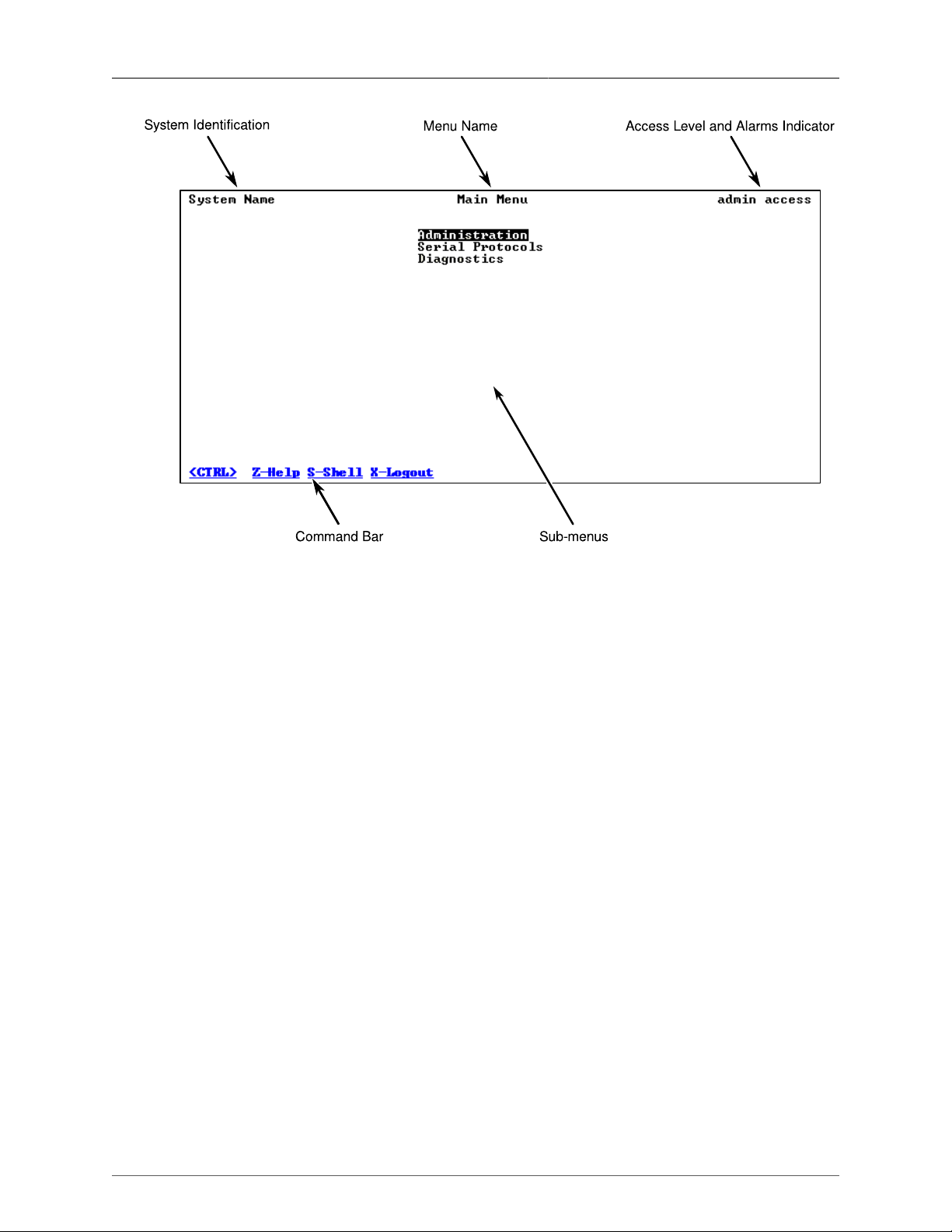
1.1.2. The Structure of the User Interface
The user interface is organized as a series of menus with an escape to a command line
interface (CLI) shell. Each menu screen presents the switch name (as provided by the
System Identification parameter), Menu Title, Access Level, Alarms indicator, Sub-Menus and
Command Bar.
Sub-menus are entered by selecting the desired menu with the arrow keys and pressing the
enter key. Pressing the escape key returns you to the parent menu.
ROS® v3.11User Guide 11 RMC30
Page 12
1. Administration
Figure 1.1. Main Menu With Screen Elements Identified
The command bar offers a list of commands that apply to the currently displayed menu. These
commands include:
• <Ctrl-Z> to display help on the current command or data item
• <Ctrl-S> to switch to the CLI shell
• <Ctrl-Up/Down> to jump to next/previous page of a status display
The main menu also provides a <Ctrl-X> command, which will terminate the session. This type
of menu is accessible via serial console, telnet session and SSH session.
1.1.3. Making Configuration Changes
When changing a data item, the user selects the data item by the cursor keys and then pressing
the enter key. The cursor will change position to allow editing of the data item.
Typing a new value after pressing enter always erases the old parameter value. The left and
right cursor keys can be used to position the edit point without erasing the old parameter value.
The up and down cursor keys can be used to cycle through the next higher and lower values
for the parameter.
After the parameter has been edited, press enter again to change other parameters. When
all desired parameters have been modified, press <Ctrl-A> to apply changes. The switch will
automatically prompt you to save changes when you leave a menu in which changes have
been made.
Some menus will require you to press <Ctrl-I> to insert a new record of information and <CtrlL> to delete a record.
ROS® v3.11User Guide 12 RMC30
Page 13

1. Administration
1.1.4. Updates Occur In Real Time
All configuration and display menus present the current values, automatically updating if
changed from other user interface sessions or SNMP. All statistics menus will display changes
to statistics as they occur.
1.1.5. Alarm Indications Are Provided
Alarms are events for which the user is notified through the Diagnostics sub-menu. All
configuration and display menus present an indication of the number of alarms (in the upper
right hand corner of the screen) as they occur, automatically updating as alarms are posted
and cleared.
1.1.6. The CLI Shell
The user interface provides a Command Line Interface shell for operations that are more easily
performed at the command line. You may switch back and forth from the menu system and
shell by pressing <Ctrl-S>. For more information on the capabilities of the shell please refer
to Chapter 5, Using the CLI Shell.
1.2. The ROS® Secure Shell Server
1.2.1. Using a Secure Shell to Access the User Interface
SSH (Secure Shell) is a network protocol which provides a replacement for insecure remote
login and command execution facilities, such as telnet and remote shell. SSH encrypts traffic
in both directions, preventing traffic sniffing and password theft.
SSH protocol version 2 is implemented in ROS®. The authentication method is “keyboardinteractive” password authentication. A user logged in via SSH has the same privileges as
one logged in via the console port.
1.2.2. Using a Secure Shell to Transfer Files
ROS® implements an SFTP server via SSH to transfer files securely. The file system visible
on the RuggedSwitch® has a single directory. The files in it are created at startup time and
can be neither deleted nor renamed. Existing files can be downloaded from the switch. For
example, firmware images may be downloaded for backup and log files may be downloaded
for analysis. Some files may be overwritten by uploading a file of the same name to the switch,
as would be done in order to upgrade the firmware.
The implemented commands are:
dir/ls
list directory contents
get
download a file from the switch
put
upload a file to the switch
ROS® v3.11User Guide 13 RMC30
Page 14

1. Administration
The files that may be overwritten via SFTP upload are:
main.bin
main ROS® firmware image
boot.bin
RuggedSwitch bootloader image
config.csv
ROS® configuration file
fpga.xsvf
FPGA configuration file
1.3. The ROS® Web Server Interface
1.3.1. Using a Web Browser to Access the Web Interface
A web browser uses a secure communications method called SSL (Secure Socket Layer) to
encrypt traffic exchanged with its clients. The web server guarantees that communications
with the client are kept private. If the client requests access via an insecure HTTP port, it will
be rerouted to the secure port. Access to the web server via SSL will be granted to a client
that provides a valid user name / password pair.
It can happen that upon connecting to the ROS® web server, a web browser may
report that it cannot verify the authenticity of the server's certificate against any of its
known certificate authorities. This is expected, and it is safe to instruct the browser to
accept the certificate. Once the browser accepts the certificate, all communications
with the web server will be secure.
Start a web browser session and open a connection to the switch by entering a URL that
specifies its host name or IP address. For example, in order to access the unit at its factory
default IP address, enter https://192.168.0.1. Once in contact with the switch, start the login
process by clicking on the “Login” link. The resulting page should be similar to that presented
below:
Figure 1.2. The ROS® log in page
To prevent unauthorized access to the device, make sure to change the default
user, admin and guest passwords before commissioning the device.
Enter the “admin” user name and the password for the admin user, and then click the
“LogIn” button. The switch is shipped with a default administrator password of “admin”. After
successfully logging in, the main menu appears.
ROS® v3.11User Guide 14 RMC30
Page 15

1. Administration
1.3.2. Customizing the Login Page
To display a custom welcome message, device information or any other information on the
login page, add text to the “banner.txt” file. If the “banner.txt” file is empty, only the username
and password fields will appear on the login page.
For more information, see Section 6.1, “Files Of Interest”.
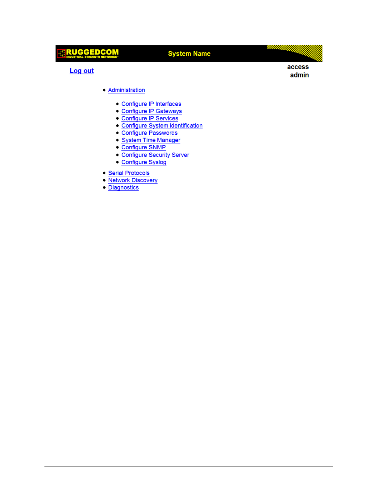
1.3.3. The Structure of the Web Interface
The user interface is organized as a series of linked web pages. The main menu provides the
links at the top level of the menu hierarchy and allows them to be expanded to display lowerlevel links for each configuration subsystem.
Figure 1.3. Main Menu via Web Server Interface
Every web page in the menu system has a common header section which contains:
• The System Name, as configured in the System Identification menu, is displayed in the top
banner, in between elements of the RuggedCom logo.
• A “Log out” link at left and immediately below the banner, terminates the current web session.
• A “Back” link at left and below “Log out” links back to the previously viewed page.
• The menu title, in the center of the page and below the banner, is a link to a context-sensitive
help page.
• The access level, e.g. “access admin”, is displayed by default at the right of the page and
below the banner. If, however, any alarms are pending, the text will be replaced with a link
which displays the number of pending alarms. Following this link displays a table of pending
alarms.
Figure 1.4. Web Page Header Showing Alarms Link
ROS® v3.11User Guide 15 RMC30
Page 16
1. Administration
1.3.4. Making Configuration Changes
When changing a data item, the user selects the data item by selecting the field to edit with
the mouse, entering a new value and clicking on the apply field. More than one parameter
may be modified at a time.
Figure 1.5. Parameters Form Example
Some menus will require you to create or delete new records of information.
1.3.5. Updating Statistics Displays
You may click the refresh button to update statistics displays.
1.4. Security Recommendations
To prevent unauthorized access to the device, note the following security recommendations:
• Do not connect the RMC30 directly to the Internet. The device should be protected by
appropriate security appliances.
• Replace the default passwords for the standard admin, operator and guest profiles before
the device is deployed.
• Use strong passwords. For more information about creating strong passwords, refer to the
password requirements in Section 1.10, “Passwords”.
1.5. Administration Menu
The Administration menu provides ability to configure network and switch administration
parameters.
ROS® v3.11User Guide 16 RMC30
Page 17
1. Administration
Figure 1.6. Administration Menu
1.6. IP Interfaces
These parameters provide the ability to configure IP connection parameters, such as address,
network, and mask. Only one IP interface can be configured.
You can choose from the following IP Address types: Static, DHCP, BOOTP, and Dynamic.
The Static IP Address type refers to the manual assignment of an IP address. The DHCP,
BOOTP, and Dynamic IP Address types refer to the automatic assignment of an IP address.
DHCP is widely used in LAN environments to dynamically assign IP addresses from a
centralized server, which reduces the overhead of administrating IP addresses.
BOOTP is a subset of the DHCP protocol. ROS® supports the transfer of a BOOTFILE via
BOOTP. The BOOTFILE represents any valid ROS® file, such as config.csv. The name of the
BOOTFILE on the BOOTP server must match the corresponding ROS® file.
The Dynamic IP Address type refers to a combination of the BOOTP and DHCP protocols.
Starting with BOOTP, the system tries BOOTP and DHCP in a round-robin fashion until it
receives a response from the corresponding server.
On non-management interfaces, only static IP addresses can be assigned.
On the management interface, the user can choose from the following IP Address types:
Static, DHCP, BOOTP and Dynamic. Static IP Address type refers to the manual assignment
of an IP address while DHCP, BOOTP and Dynamic IP Address types refer to the automatic
assignment of an IP address.
DHCP is widely used in LAN environments to dynamically assign IP addresses from a
centralized server, which reduces the overhead of administrating IP addresses.
ROS® v3.11User Guide 17 RMC30
Page 18

1. Administration
BOOTP is a subset of the DHCP protocol. ROS® supports the transfer of a BOOTFILE via
BOOTP. The BOOTFILE represents any valid ROS® file such as config.csv. The name of
BOOTFILE on the BOOTP server must match the corresponding ROS® file.
The Dynamic IP Address type refers to a combination of the BOOTP and DHCP protocols.
Starting with BOOTP, the system will try BOOTP and DHCP in a round-robin fashion until it
receives a response from the corresponding server.
You can use the ROS® web interface to change the IP Address Type of the
management interface from Static to DHCP. However, after doing so, you cannot
use the web interface to change the IP Address Type back to Static and set an IP
address. If you need to change the IP Address Type of the management interface
from DHCP to Static, configure the setting through a telnet, SSH, RSH, or serial
port connection, or upload a new configuration file to the device.
IP Address Type
Synopsis: { Static, Dynamic, DHCP, BOOTP }
Default: Static
Specifies whether the IP address is static or is dynamically assigned via DHCP or BOOTP.
The Dynamic option automatically switches between BOOTP and DHCP until it receives
a response from the relevant server. The Static option must be used for non-management
interfaces.
IP Address
Synopsis: ###.###.###.### where ### ranges from 0 to 255
Default: 192.168.0.1
Specifies the IP address of this device. An IP address is a 32-bit number that is notated by
using four numbers from 0 through 255, separated by periods. Only a unicast IP address
is allowed, which ranges from 1.0.0.0 to 233.255.255.255.
Subnet
Synopsis: ###.###.###.### where ### ranges from 0 to 255
Default: 255.255.255.0
Specifies the IP subnet mask of this device. An IP subnet mask is a 32-bit number that is
notated by using four numbers from 0 through 255, separated by periods. Typically, subnet
mask numbers use either 0 or 255 as values (e.g. 255.255.255.0) but other numbers can
appear.
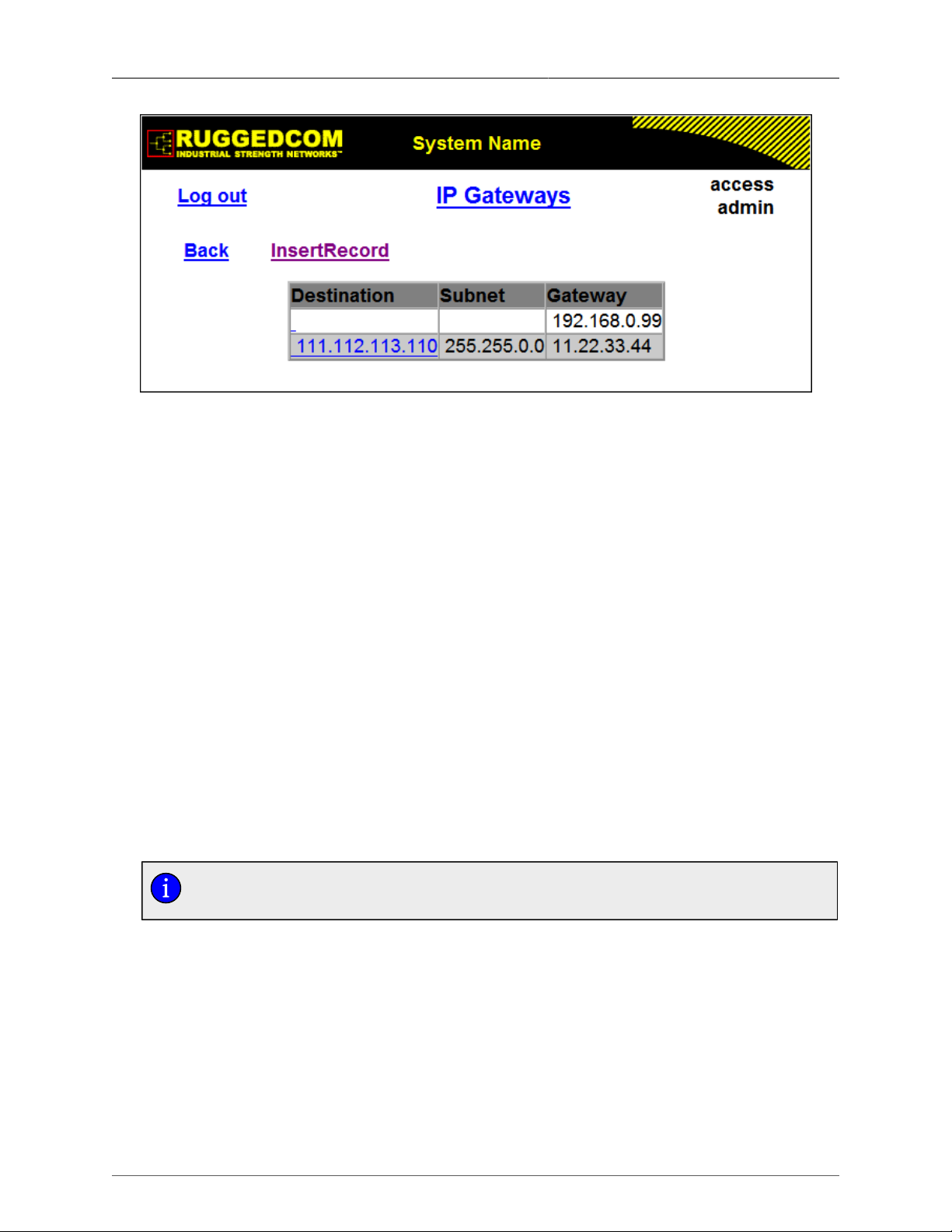
1.7. IP Gateways
These parameters provide the ability to configure gateways. A maximum of 10 gateways can
be configured. When both the Destination and Subnet fields are both 0.0.0.0 (displayed as
blank space), the gateway is a default gateway.
ROS® v3.11User Guide 18 RMC30
Page 19
1. Administration
Figure 1.7. IP Gateways Form
Destination
Synopsis: ###.###.###.### where ### ranges from 0 to 255
Default: 0.0.0.0
Specifies the IP address of the destination device. An IP address is a 32-bit number that
is notated by using four numbers from 0 through 255, separated by periods.
Subnet
Synopsis: ###.###.###.### where ### ranges from 0 to 255
Default: 0.0.0.0
Specifies the IP subnet mask of the destination. An IP subnet mask is a 32-bit number
that is notated by using four numbers from 0 through 255, separated by periods. Typically,
subnet mask numbers use either 0 or 255 as values (e.g. 255.255.255.0) but other
numbers can appear.
Gateway
Synopsis: ###.###.###.### where ### ranges from 0 to 255
Default: 0.0.0.0
Specifies the gateway IP address. The gateway address must be on the same IP subnet
as this device.
The default gateway configuration will not be changed when resetting all
configuration parameters to defaults.
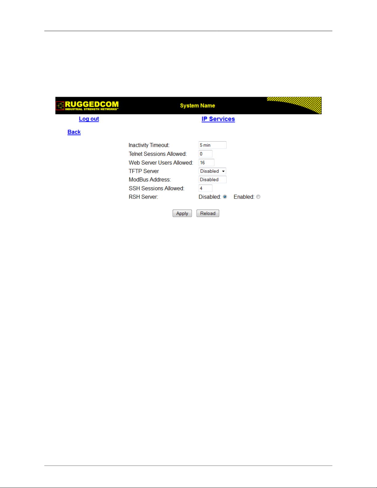
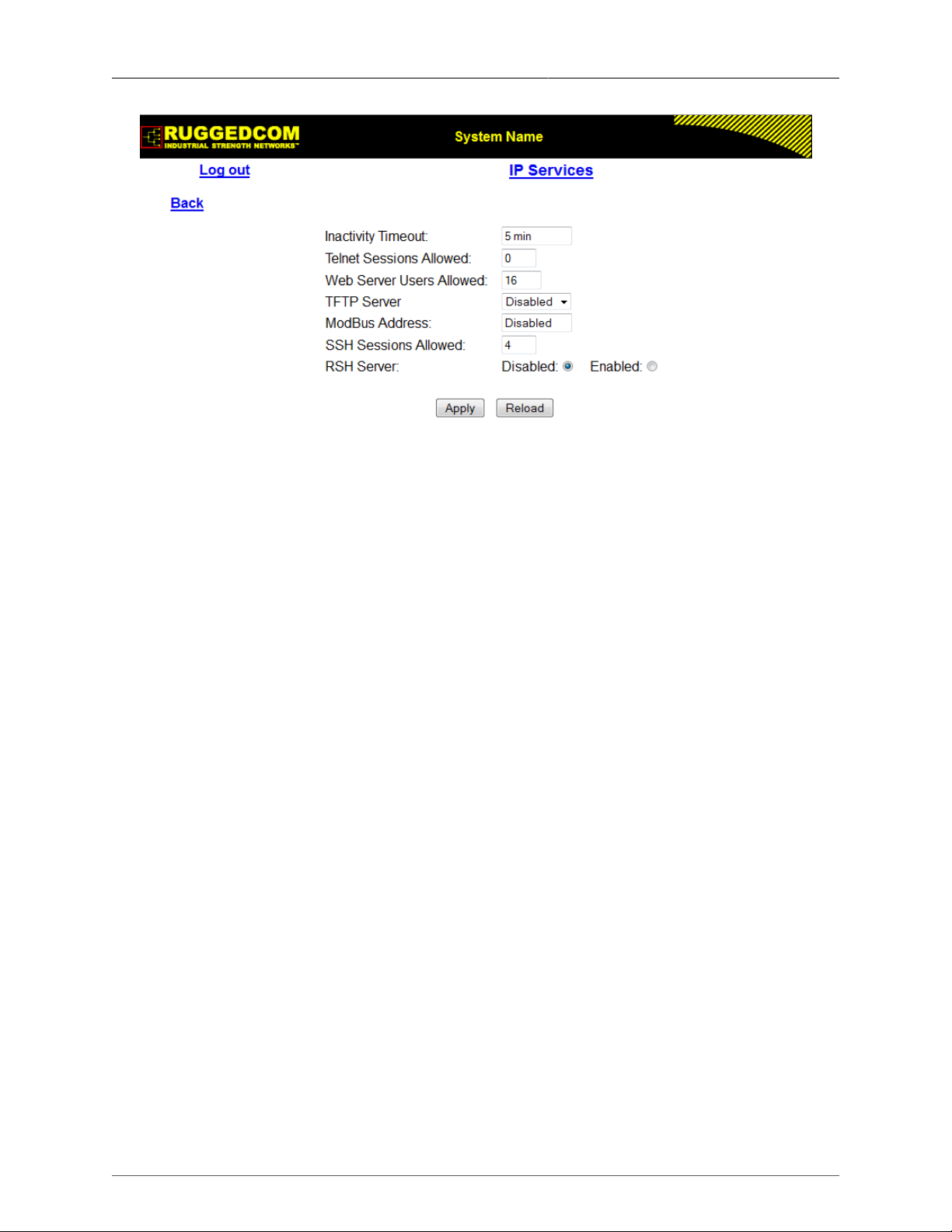
1.8. IP Services
These parameters provide the ability to configure properties for IP services provided by the
device.
ROS® v3.11User Guide 19 RMC30
Page 20
1. Administration
Figure 1.8. IP Services Form
Inactivity Timeout
Synopsis: 1 to 60 or { Disabled }
Default: 5 min
Specifies when the console will timeout and display the login screen if there is no user
activity. A value of zero disables timeouts for console and Telnet users. For Web Server
users maximum timeout value is limited to 30 minutes.
Telnet Sessions Allowed
Synopsis: 0 to 4
Default: 0 (controlled version)
Default: 4 (non-controlled version)
Limits the number of Telnet sessions. A value of zero prevents any Telnet access.
Web Server Users Allowed
Synopsis: 1 to 16
Default: 16
Limits the number of simultaneous web server users.
TFTP Server
Synopsis: { Disabled, Get Only, Enabled }
Default: Disabled
As TFTP is a very insecure protocol, this parameter allows the user to limit or disable TFTP
Server access.
DISABLED - disables read and write access to TFTP Server
GET ONLY - only allows reading of files via TFTP Server
ENABLED - allows reading and writing of files via TFTP Server
ModBus Address
Synopsis: 1 to 254 or { Disabled }
Default: Disabled
Determines the Modbus address to be used for Management through Modbus.
ROS® v3.11User Guide 20 RMC30
Page 21

1. Administration
SSH Sessions Allowed (Controlled Version Only)
Synopsis: 1 to 4
Default: 4
Limits the number of SSH sessions.
RSH Server
Synopsis: { Disabled, Enabled }
Default: Disabled (controlled version)
Default: Enabled (non-controlled version)
Disables/enables Remote Shell access.
1.9. System Identification
The system identification is displayed in the sign-on screen and in the upper left hand corner
of all ROS® screens.
Figure 1.9. System Identification Form
System Name
Synopsis: Any 19 characters
Default: System Name
The system name is displayed in all ROS® menu screens. This can make it easier to
identify the switches within your network, provided that all switches are given a unique
name.
Location
Synopsis: Any 49 characters
Default: Location
The location can be used to indicate the physical location of the switch. It is displayed in
the login screen as another means to ensure you are dealing with the desired switch.
Contact
Synopsis: Any 49 characters
Default: Contact
The contact can be used to help identify the person responsible for managing the switch.
You can enter name, phone number, email, etc. It is displayed in the login screen so that
this person may be contacted, should help be required.
ROS® v3.11User Guide 21 RMC30
Page 22
1. Administration
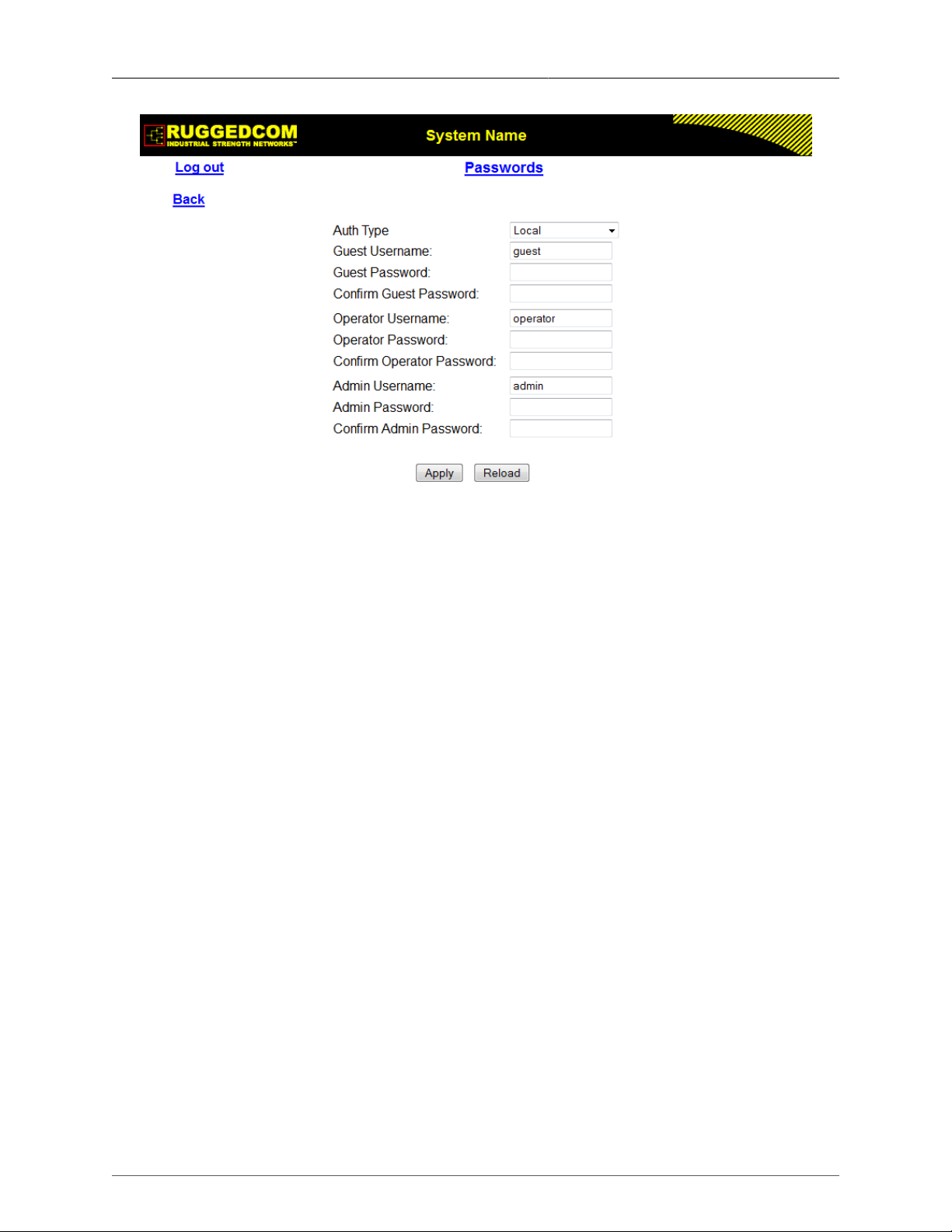
1.10. Passwords
These parameters provide the ability to configure parameters for authorized and authenticated
access to the device's services (HMI via Serial Console, Telnet, SSH, RSH, Web Server).
Access to the switch can be authorized and authenticated via RADIUS or TACACS+ servers,
or using locally configured passwords that are configured per user name and access level.
Note that access via the Serial Console is authorized first using local settings. If a local match
is not found, RADIUS/TACACS+ will be used if enabled. For all other services, if RADIUS
or TACACS+ is enabled for authentication and authorization, but is unreachable, the local
settings will be used if configured.
To access the unit, the user name and password must be provided.
Three user names and passwords can be configured. They correspond to three access levels,
which provide or restrict access to change settings and execute various commands within the
device.
• guest users can view most settings, but may not change settings or run commands
• operator cannot change settings, but can reset alarms, clear statistics and logs
• admin user can change all the settings and run commands
To prevent unauthorized access to the device, make sure to change the default
user, admin and guest passwords before commissioning the device.
When creating a new password, it should adhere to the following rules:
• Must not be less than 6 characters in length.
• Must not include the username or any 4 continous alphanumeric characters found in
the username. For example, if the username is Subnet25, the password may not be
subnet25admin or subnetadmin. However, net25admin or Sub25admin is permitted.
• Must have at least one alphabetic character and one number. Special characters are
permitted.
• Must not have more than 3 continuously incrementing or decrementing numbers. For
example, Sub123 and Sub19826 are permitted, but Sub12345 is not.
An alarm will generate if a weak password is configured. The weak password alarm can
be disabled by user. For more information about disabling alarms, refer to Section 4.1.4,
“Configuring Alarms”.
ROS® v3.11User Guide 22 RMC30
Page 23
1. Administration
Figure 1.10. Passwords Form
Auth Type
Synopsis: { Local, RADIUS, TACACS+, RADIUSorLocal, TACACS
+orLocal }
Default: Local
Password authentication can be performed using locally configured values, a remote
RADIUS server, or a remote TACACS+ server. Setting this value to one of the
combinations that includes RADIUS or TACACS+ requires that the Security Server Table
be configured.
• Local - authentication from the local Password Table
• RADIUS - authentication using a RADIUS server
• TACACS+ - authentication using a TACACS+ server
• RADIUSOrLocal - authentication using RADIUS. If the server cannot be reached,
authenticate from the local Password Table.
• TACACS+OrLocal - authentication using TACACS+. If the server cannot be reached,
authenticate from the local Password Table
Guest Username
Synopsis: 15 character ASCII string
Default: guest
Related password is in the Guest Password field; view only, cannot change settings or
run any commands.
Guest Password
Synopsis: 15 character ASCII string
Default: guest
Related user name is in the Guest Username field; view only, cannot change settings or
run any commands.
ROS® v3.11User Guide 23 RMC30
Page 24

1. Administration
Confirm Guest Password
Synopsis: 15 character ASCII string
Default: None
Confirm the input of the above Guest Password.
Operator Username
Synopsis: 15 character ASCII string
Default: operator
Related password is in the Oper Password field; cannot change settings; can reset alarms,
statistics, logs, etc.
Operator Password
Synopsis: 15 character ASCII string
Default: operator
Related user name is in the Oper Username field; cannot change settings; can reset
alarms, statistics, logs, etc.
Confirm Operator Password
Synopsis: 15 character ASCII string
Default: None
Confirm the input of the above Operator Password.
Admin Username
Synopsis: 15 character ASCII string
Default: admin
Related password is in the Admin Password field; full read/write access to all settings and
commands.
Admin Password
Synopsis: 15 character ASCII string
Default: admin
Related user name is in the Admin Username field; full read/write access to all settings
and commands.
Confirm Admin Password
Synopsis: 15 character ASCII string
Default: None
Confirm the input of the above Admin Password.
1.11. System Time Management
ROS® running on the RMC30 offers the following time-keeping and time synchronization
features:
• Local hardware time keeping and time zone management
• SNTP time synchronization
1.11.1. Configuring System Time
The System Time Manager option within the ROS® Administration menu fully configures time
keeping functions on a ROS®-based device:
ROS® v3.11User Guide 24 RMC30
Page 25
1. Administration
Figure 1.11. System Time Manager Menu
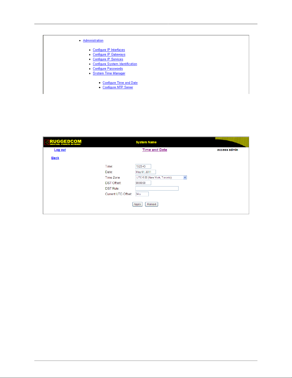
1.11.1.1. Configuring Time and Date
This menu configures the current time, date, time zone, and DST (Daylight Savings Time)
settings.
Figure 1.12. Time and Date Form
Time
Synopsis: HH:MM:SS
This parameter enables both the viewing and setting of the local time.
Date
Synopsis: MMM DD, YYYY
This parameter enables both the viewing and setting of the local date.
Time Zone
Synopsis: {
UTC-12:00 (Eniwetok, Kwajalein), UTC-11:00 (Midway Island,
Samoa),
UTC-10:00 (Hawaii), UTC-9:00 (Alaska), UTC-8:00 (Los Angeles,
Vancouver),
UTC-7:00 (Calgary, Denver), UTC-6:00 (Chicago, Mexico City),
UTC-5:00 (New York, Toronto), UTC-4:00 (Caracas, Santiago),
UTC-3:30 (Newfoundland), UTC-3:00 (Brasilia, Buenos Aires),
UTC-2:00 (Mid Atlantic), UTC-1:00 (Azores),
UTC-0:00 (Lisbon, London), UTC+1:00 (Berlin, Paris, Rome),
ROS® v3.11User Guide 25 RMC30
Page 26

1. Administration
UTC+2:00 (Athens, Cairo, Helsinki), UTC+3:00 (Baghdad, Moscow),
UTC+3:30 (Teheran), UTC+4:00 (Abu Dhabi, Kazan, Muscat),
UTC+4:30 (Kabul), UTC+5:00 (Islamabad, Karachi),
UTC+5:30 (Calcutta, New Delhi), UTC+5:45 (Kathmandu),
UTC+6:00 (Almaty, Dhaka), UTC+6:30 (Rangoon),
UTC+7:00 (Bangkok, Hanoi), UTC+8:00 (Beijing, Hong Kong)
UTC+9:00 (Seoul, Tokyo), UTC+9:30 (Adelaide, Darwin),
UTC+10:00 (Melbourne, Sydney), UTC+11:00 (Magadan, New
Caledonia),
UTC+12:00 (Auckland, Fiji) }
Default: UTC-0:00 (Lisbon, London)
This setting enables the conversion of UTC (Universal Coordinated Time) to local time.
DST Offset
Synopsis: HH:MM:SS
Default:00:00:00
This parameter specifies the amount of time to be shifted forward/backward when DST
begins and ends. For example, for most of the USA and Canada, DST time shift is 1 hour
(01:00:00) forward when DST begins and 1 hour backward when DST ends.
DST Rule
Synopsis: mm.n.d/HH:MM:SS mm.n.d/HH:MM:SS
Default:
This parameter specifies a rule for time and date when the transition between Standard
and Daylight Saving Time occurs.
• mm - Month of the year (01 - January, 12 - December)
• n - week of the month (1 - 1st week, 5 - 5th/last week)
• d - day of the week (0 - Sunday, 6 - Saturday)
• HH - hour of the day (0 - 24)
• MM - minute of the hour (0 - 59)
• SS - second of the minute (0 - 59)
Example: The following rule applies in most of the USA and Canada:
03.2.0/02:00:00 11.1.0/02:00:00
In the example, DST begins on the second Sunday in March at 2:00am, and ends on the
first Sunday in November at 2:00am.
Current UTC Offset
Synopsis: 0 s to 1000 s
Default: 34 s
Coordinated Universal Time (UTC) is a time standard based on International Atomic
Time (TAI) with leap seconds added at irregular intervals to compensate for the Earth's
slowing rotation. The Current UTC Offset parameter allows the user to adjust the difference
between UTC and TAI. The International Earth Rotation and Reference System Service
(IERS) observes the Earth's rotation and nearly six months in advance (January and July)
a Bulletin-C message is sent out, which reports whether or not to add a leap second in
the end of June and December.
Please note that change in the Current UTC Offset parameter will result in a temporary
disruption in the timing network.
ROS® v3.11User Guide 26 RMC30
Page 27
1. Administration
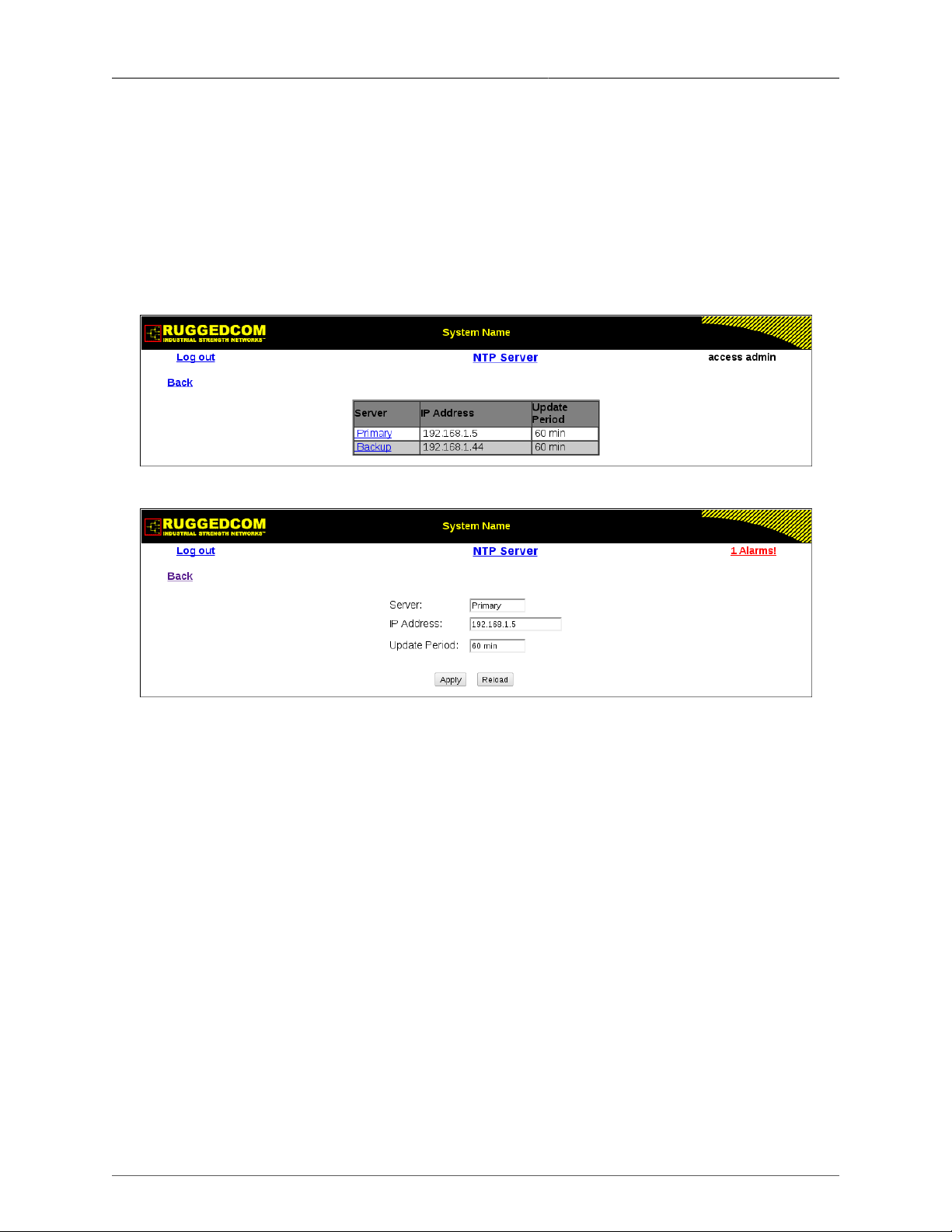
1.11.1.2. Configuring NTP Service
ROS® may optionally be configured to refer periodically to a specified NTP server to correct
any accumulated drift in the on-board clock. ROS® will also serve time via SNTP to hosts
that request it.
Two NTP servers (primary and secondary) may be configured for the device. The primary
server is contacted first upon each attempt to update the system time. If the primary server
fails to respond, the secondary server is contacted. If either the primary or secondary server
fails to respond, an alarm is raised.
Figure 1.13. NTP Server List
Figure 1.14. NTP Server Form
Server
Synopsis: Primary, Secondary
This field displays the chosen NTP server. The remaining fields on this form correspond
to the chosen server.
IP Address
Synopsis: ###.###.###.### where ### ranges from 0 to 255
Default:
This parameter specifies the IP address of an (S)NTP server ((Simple) Network Time
Protocol); programming an address of '0.0.0.0' disables SNTP requests. This device is an
SNTP client which may connect to only one server. If a server address is programmed
then a manual setting of the time will be overwritten at the next update period.
Update Period
Synopsis: 1 to 1440
Default: 60 min
This setting determines how frequently the (S)NTP server is polled for a time update. If the
server cannot be reached, three attempts are made at one-minute intervals and then an
alarm is generated, at which point the programmed rate is resumed.
ROS® v3.11User Guide 27 RMC30
Page 28
1. Administration
1.12. SNMP Management
ROS® supports Simple Network Management Protocol Versions 1 (SNMPv1), 2 (SNMPv2c),
and 3 (SNMPv3). SNMPv3 protocol provides secure access to devices by a combination of
authentication and packet encryption over the network. SNMPv3 security features include the
following:
• message integrity – ensures that a packet has not been tampered with in-transit.
• authentication – determines the message is from a valid source.
• encryption – scrambles the contents of a packet to prevent it from being seen by an
unauthorized source.
SNMPv3 provides security models and security levels. A security model is an authentication
strategy that is set up for a user and the group in which the user resides. A security level is
a permitted level of security within a security model. A combination of a security model and
security level will determine which security mechanism is employed when handling an SNMP
packet.
Note the following about the SNMPv3 protocol:
• each user belongs to a group.
• a group defines the access policy for a set of users.
• an access policy defines what SNMP objects can be accessed for: reading, writing and
creating notifications.
• a group determines the list of notifications its users can receive.
• a group also defines the security model and security level for its users.
Community is configured for protocols v1 and v2c. Community is mapped to the group and
access level with security name (which is configured as User name).
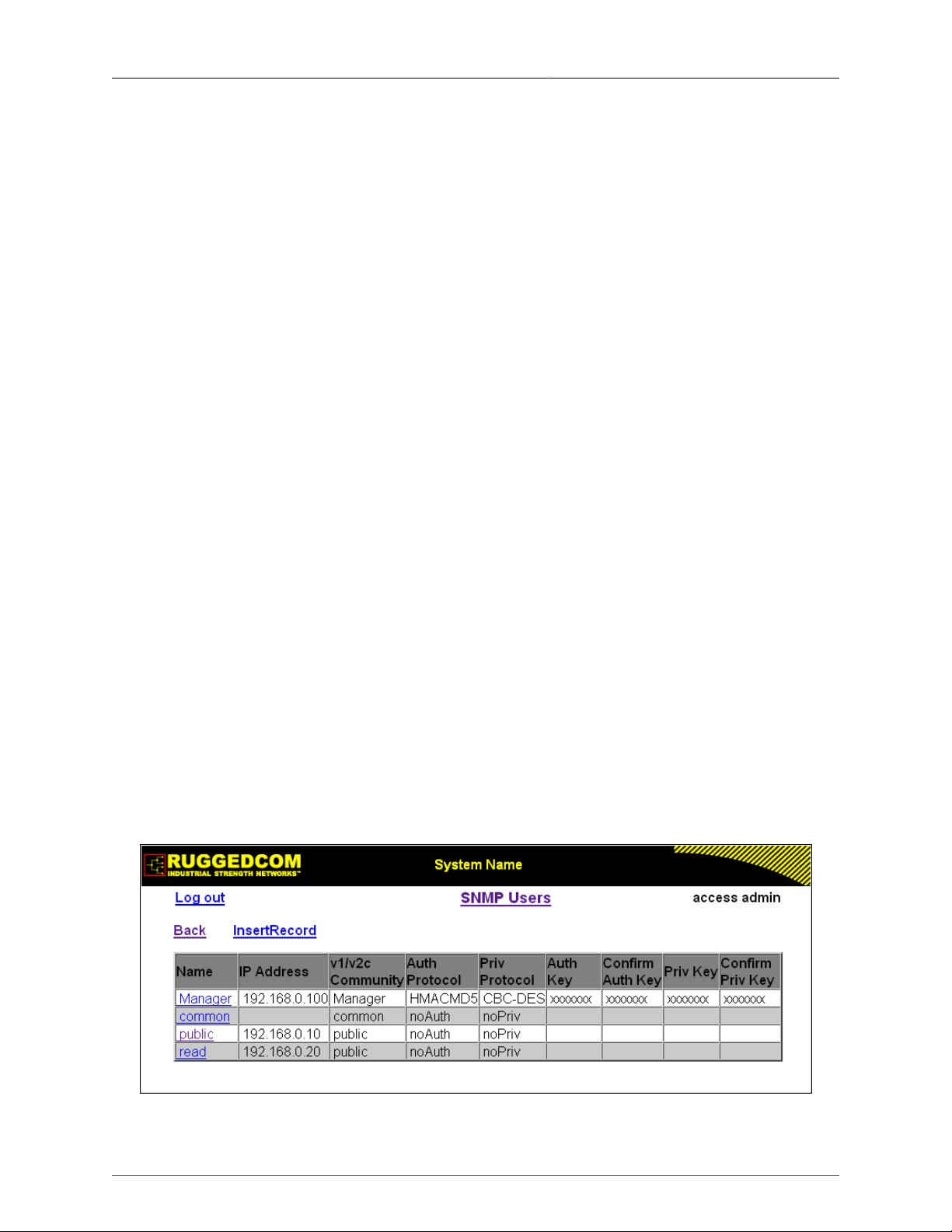
1.12.1. SNMP Users
These parameters provide the ability to configure users for the local SNMPv3 engine, along
with the community for SNMPv1 and SNMPv2c. Note that when employing the SNMPv1 or
SNMPv2c security level, the User Name maps the community name with the security group
and access level. Up to 32 entries can be configured.
Figure 1.15. SNMP User Table
ROS® v3.11User Guide 28 RMC30
Page 29
1. Administration
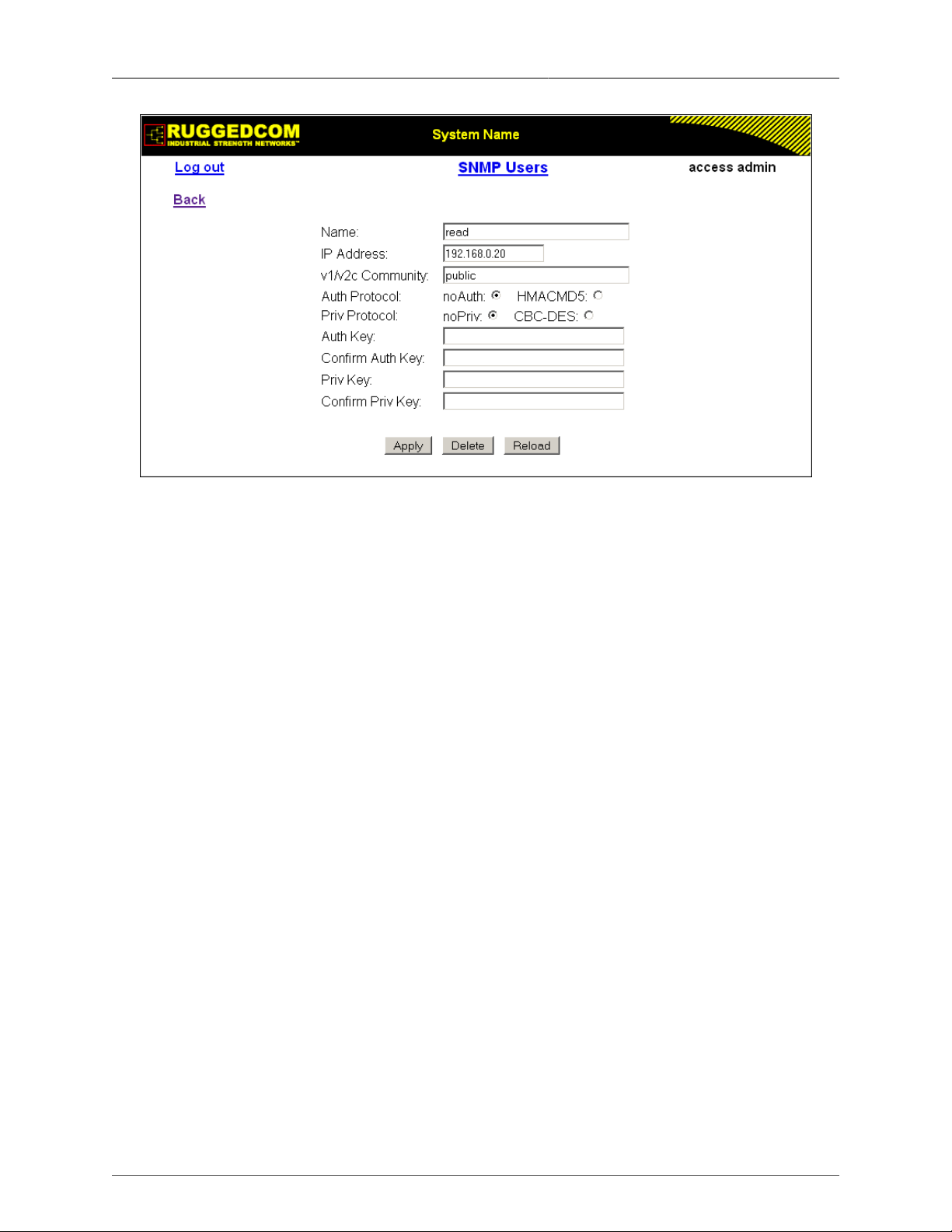
Figure 1.16. SNMP User Form
Name
Synopsis: Any 32 characters
Default: initial
The name of the user. This user name also represents the security name that maps this
user to the security group.
IP Address
Synopsis: ###.###.###.### where ### ranges from 0 to 255
Default:
The IP address of the user's SNMP management station. If IP address is configured, SNMP
requests from that user will be verified by IP address as well. SNMP Authentication trap
will be generated to trap receivers if request was received from this user, but from any
other IP address. If IP address is empty, traps can not be generated to this user, but SNMP
requests will be served for this user from any IP address.
v1/v2c Community
Synopsis: Any 32 characters
Default:
The community string which is mapped by this user/security name to the security group if
security model is SNMPv1 or SNMPv2c. If this string is left empty, it will be assumed to
be equal to the same as user name.
Auth Protocol
Synopsis: { noAuth, HMACMD5 }
Default: noAuth
An indication of whether messages sent on behalf of this user to/from SNMP engine, can
be authenticated, and if so, the type of authentication protocol which is used.
Priv Protocol
Synopsis: { noPriv, CBC-DES }
ROS® v3.11User Guide 29 RMC30
Page 30

1. Administration
Default: noPriv
An indication of whether messages sent on behalf of this user to/from SNMP engine can
be protected from disclosure, and if so, the type of privacy protocol which is used.
Auth Key
Synopsis: 31 character ASCII string
Default:
The secret authentication key (password) that must be shared with SNMP client. if the key
is not an emtpy string, it must be at least 6 characters long.
Confirm Auth Key
Synopsis: 31 character ASCII string
Default:
The secret authentication key (password) that must be shared with SNMP client. if the key
is not an emtpy string, it must be at least 6 characters long.
Priv Key
Synopsis: 31 character ASCII string
Default:
The secret encription key (password) that must be shared with SNMP client. if the ke is
not an emtpy string, it must be at least 6 characters long.
Priv Key
Synopsis: 31 character ASCII string
Default:
The secret encription key (password) that must be shared with SNMP client. if the ke is
not an emtpy string, it must be at least 6 characters long.
1.12.2. SNMP Security to Group Maps
Entries in this table map configuration of security model and security name (user) into a group
name, which is used to define an access control policy. Up to 32 entries can be configured.
Figure 1.17. SNMP Security to Group Maps Table
ROS® v3.11User Guide 30 RMC30
Page 31

1. Administration
Figure 1.18. SNMP Security to Group Maps Form
SecurityModel
Synopsis: { snmpV1, snmpV2c, snmpV3 }
Default: snmpV3
The Security Model that provides the name referenced in this table.
Name
Synopsis: Any 32 characters
Default:
The user name which is mapped by this entry to the specified group name.
Group
Synopsis: Any 32 characters
Default:
The group name to which the security model and name belong. This name is used as an
index to the SNMPv3 VACM Access Table.
1.12.3. SNMP Access
These parameters provide the ability to configure access rights for groups.To determine
whether access is allowed, one entry from this table needs to be selected and the proper view
name from that entry must be used for access control checking. View names are predefined:
• noView - access is not allowed
• V1Mib - SNMPv3 MIBs excluded
• allOfMibs - all supported MIBs are included.
ROS® v3.11User Guide 31 RMC30
Page 32

1. Administration
Figure 1.19. SNMP Access Table
Figure 1.20. SNMP Access Form
Group
Synopsis: Any 32 characters
Default:
The group name to which the security model and name belong. This name is used as an
index to the SNMPv3 VACM Access Table.
SecurityModel
Synopsis: { snmpV1, snmpV2c, snmpV3 }
Default: snmpV3
In order to gain the access rights allowed by this entry, the configured security model must
be in use.
SecurityLevel
Synopsis: { noAuthNoPriv, authNoPriv, authPriv }
Default: noAuthNoPriv
The minimum level of security required in order to gain the access rights allowed by this
entry. A security level of noAuthNoPriv is less than authNoPriv, which is less than authPriv.
ReadViewName
Synopsis: { noView, V1Mib, allOfMib }
Default: noView
ROS® v3.11User Guide 32 RMC30
Page 33

1. Administration
This parameter identifies the MIB tree(s) to which this entry authorizes read access. If the
value is noView, then read access will not be granted.
WriteViewName
Synopsis: { noView, V1Mib, allOfMib }
Default: noView
This parameter identifies the MIB tree(s) to which this entry authorizes write access. If the
value is noView, then write access will not be granted.
NotifyViewName
Synopsis: { noView, V1Mib, allOfMib }
Default: noView
This parameter identifies the MIB tree(s) to which this entry authorizes access for
notifications. If the value is noView, then access for notifications will not be granted.
1.13. RADIUS
RADIUS (Remote Authentication Dial In User Service) is used to provide centralized
authentication and authorization for network access. ROS® assigns a privilege level of Admin,
Operator or Guest to a user who presents a valid user name and password. The number of
users who can access the ROS® server is ordinarily dependent on the number of user records
which can be configured on the server itself. ROS® can also, however, be configured to pass
along the credentials provided by the user to be remotely authenticated by a RADIUS server. In
this way, a single RADIUS server can centrally store user data and provide authentication and
authorization service to multiple ROS® servers needing to authenticate connection attempts.
1.13.1. RADIUS overview
RADIUS (described in RFC 2865 [http://tools.ietf.org/html/rfc2865]) is a UDP-based protocol
used for carrying authentication, authorization, and configuration information between a
Network Access Server which desires to authenticate its links and a shared Authentication
Server.
A RADIUS server can act as a proxy client to other RADIUS servers or other kinds of
authentication servers.
Unlike TACACS+, authorization and authentication functionality is supported by RADIUS in
the same packet frame. TACACS+ actually separates authentication from authorization into
separate packets.
On receiving an authentication-authorization request from a client in an “Access-Request”
packet, the RADIUS server checks the conditions configured for received username-password
combination in the user database. If all the conditions are met, the list of configuration values
for the user is placed into an “Access-Accept” packet. These values include the type of service
(e.g. SLIP, PPP, Login User) and all the necessary values to deliver the desired service.
1.13.2. User Login Authentication and Authorization
A RADIUS server can be used to authenticate and authorize access to the device's services,
such as HMI via Serial Console, Telnet, SSH, RSH, Web Server (see Password Configuration).
ROS® implements a RADIUS client which uses the Password Authentication Protocol (PAP)
to verify access. Attributes sent to a RADIUS server are:
ROS® v3.11User Guide 33 RMC30
Page 34

1. Administration
• user name
• user password
• service type: Login
• vendor specific, currently defined as the following:
vendor ID: RuggedCom Inc. enterprise number (15004) assigned by the Internet Assigned
Numbers Authority (IANA)
string, sub-attribute containing specific values:
subtype: 1 (vendor's name subtype)
length: 11 (total length of sub-attribute of subtype 1)
ASCII string “RuggedCom”
Two RADIUS servers (Primary and Secondary) are configurable per device. If the Primary
Server is not reachable, the device will automatically fall back to the Secondary server to
complete the authorization process.
The vendor specific attribute is used to determine the access level from the server, which may
be configured at the RADIUS server with the following information:
• Vendor ID: RuggedCom Inc. enterprise number (15004) assigned by Internet Assigned
Numbers Authority (IANA)
• Sub-attribute Format: String
• Vendor Assigned Sub-Attribute Number: 2
• Attribute value – any one of: admin, operator, guest
If no access level is received in the response packet from the server then no access
will be granted to the user
An Example of a RuggedCom Dictionary for a FreeRADIUS server:
VENDOR RuggedCom 15004
BEGIN-VENDOR RuggedCom
ATTRIBUTE RuggedCom-Privilege-level 2 string
END-VENDOR RuggedCom
Sample entry for user “admin” Adding Users:
admin Auth-Type := Local, User-Password == “admin”
RuggedCom-Privilege-level = “admin”
ROS® v3.11User Guide 34 RMC30
Page 35

1. Administration
1.13.3. Radius Server Configuration
Figure 1.21. RADIUS Server Summary
Figure 1.22. RADIUS Server Form
Server
Synopsis: Any 8 characters
Default: Primary
This field tells whether this configuration is for a primary or a backup server
ROS® v3.11User Guide 35 RMC30
Page 36

1. Administration
IP Address
Synopsis: ###.###.###.### where ### ranges from 0 to 255
Default:
The RADIUS server IP Address.
Auth UDP Port
Synopsis: 1 to 65535
Default: 1812
The authentication UDP Port on the RADIUS server.
Auth Key
Synopsis: 31 character ASCII string
Default: None
The authentication key shared with the RADIUS server. It is used to encrypt any passwords
that are sent between the switch and the RADIUS server.
Confirm Auth Key
Synopsis: 31 character ASCII string
Default: None
Confirm input of the above authentication key.
1.14. TACACS+
TACACS+ (Terminal Access Controller Access-Control System Plus) is a TCP-based access
control protocol that provides authentication, authorization and accounting services to routers,
network access servers and other networked computing devices via one or more centralized
servers. It is based on, but is not compatible with, the older TACACS protocol. TACACS+
has generally replaced its predecessor in more recently built or updated networks, although
TACACS and XTACACS are still used on many older networks. Note that RuggedCom's
TACACS+ client implementation always has encryption enabled.
1.14.1. User Login Authentication and Authorization
A TACACS+ server can be used to authenticate and authorize access to the device's services,
such as HMI via Serial Console, Telnet, SSH, RSH, Web Server (see Password Configuration).
User name and Password are sent to the configured TACACS+ Server.
Two TACACS+ servers (Primary and Secondary) are configurable per device. If the primary
server is not reachable, the device will automatically fall back to the secondary server to
complete the authorization process.
ROS® v3.11User Guide 36 RMC30
Page 37

1. Administration
1.14.2. TACACS+ Server Configuration
Figure 1.23. TACACS+ Server Summary
Figure 1.24. TACACS+ Server Form
Server
Synopsis: Any 8 characters
Default: Primary
This field indicates whether this configuration is for a primary or a backup server.
ROS® v3.11User Guide 37 RMC30
Page 38

1. Administration
IP Address
Synopsis: ###.###.###.### where ### ranges from 0 to 255
Default:
The TACACS+ server IP Address.
Auth TCP Port
Synopsis: 1 to 65535
Default: 49
The authentication TCP Port on the TACACS+ server.
Auth Key
Synopsis: 31 character ASCII string
Default:
The authentication key shared with the TACACS+ server. It is used to encrypt any
passwords that are sent from the switch to the TACACS+ server.
Confirm Auth Key
Synopsis: 31 character ASCII string
Default: None
Confirm input of the above authentication key.
1.14.3. User Privilge Level Configuartion
The TACACS+ standard priv_lvl attribute is used to grant access to the device. By default, the
attribute uses the following ranges:
• priv_lvl=15 represents an access level of “admin”
• 1 < priv_lvl < 15 (any value from 2 to 14) represents an access level of “operator”
• priv_lvl=1 represents an access level of “guest”
You can also configure a different non-default access level for admin, operator or guest users.
If an access level is not received in the response packet from the server, access
is not be granted to the user.
1.14.4. TACACS+ Server Privilege Configuration
Figure 1.25. TACACS+ Server Privilege Form
ROS® v3.11User Guide 38 RMC30
Page 39

1. Administration
Admin Priv
Synopsis: (0 to 15)-(0 to 15)
Default: 15
Privilege level to be assigned to the user.
Oper Priv
Synopsis: (0 to 15)-(0 to 15)
Default: 2-14
Privilege level to be assigned to the user.
Guest Priv
Synopsis: (0 to 15)-(0 to 15)
Default: 1
Privilege level to be assigned to the user.
1.15. Syslog
The syslog provides users with the ability to configure local and remote syslog connections.
The remote syslog protocol, defined in RFC 3164, is a UDP/IP-based transport that enables a
device to send event notification messages across IP networks to event message collectors,
also known as syslog servers. The protocol is simply designed to transport these event
messages from the generating device to the collector.
The syslog client resides in ROS® and supports up to 5 collectors (syslog servers). ROS®
Remote Syslog provides the ability to configure:
• IP address(es) of collector(s).
• Source UDP port.
• Destination UDP port per collector.
• Syslog source facility ID per collector (same value for all ROS® modules).
• Filtering severity level per collector (in case different collectors are interested in syslog
reports with different severity levels).
1.15.1. Configuring Local Syslog
The local syslog configuration enables users to control what level of syslog information will
be logged. Only messages of a severity level equal to or greater than the configured severity
level are written to the syslog.txt file in the unit.
ROS® v3.11User Guide 39 RMC30
Page 40

1. Administration
Figure 1.26. Local Syslog Form
Local Syslog Level
Synopsis: { EMERGENCY, ALERT, CRITICAL, ERROR, WARNING, NOTICE,
INFORMATIONAL, DEBUGGING }
Default: INFORMATIONAL
The severity of the message that has been generated. Note that the severity level selected
is considered the minimum severity level for the system. For example, if ERROR is
selected, the system sends any syslog messages generated by Error, Critical, Alert and
Emergency.
1.15.2. Configuring Remote Syslog Client
Figure 1.27. Remote Syslog Client Form
UDP Port
Synopsis: 1025 to 65535 or { 514 }
Default: 514
The local UDP port through which the client sends information to the server(s).
ROS® v3.11User Guide 40 RMC30
Page 41

1. Administration
1.15.3. Configuring the Remote Syslog Server
Figure 1.28. Remote Syslog Server Table
Figure 1.29. Remote Syslog Server Form
IP Address
Synopsis: ###.###.###.### where ### ranges from 0 to 255
Default:
Syslog server IP Address.
UDP Port
Synopsis: 1025 to 65535 or { 514 }
Default: 514
The UDP port number on which the remote server listens.
Facility
Synopsis: { USER, LOCAL0, LOCAL1, LOCAL2, LOCAL3, LOCAL4, LOCAL5,
LOCAL6, LOCAL7 }
ROS® v3.11User Guide 41 RMC30
Page 42

1. Administration
Default: LOCAL7
Syslog facility name - { USER, LOCAL0, LOCAL1, LOCAL2, LOCAL3, LOCAL4, LOCAL5,
LOCAL6, LOCAL7 }.
Syslog Facility is an information field associated with a syslog message. The syslog facility
is the application or operating system component that generates a log message. ROS®
maps all syslog logging information onto a single facility, which is configurable to facilitate
a remote syslog server.
Severity
Synopsis: { EMERGENCY, ALERT, CRITICAL, ERROR, WARNING, NOTICE,
INFORMATIONAL, DEBUGGING }
Default: DEBUGGING
Syslog severity level - {EMERGENCY, ALERT, CRITICAL, ERROR, WARNING, NOTICE,
INFORMATIONAL, DEBUGGING}.
The severity level is the severity of the generated message. Note that the selected severity
level is accepted as the minimum severity level for the system. For example, if the severity
level is set as “Error”, then the system sends any syslog message generated by Error,
Critical, Alert and Emergency events.
1.16. Troubleshooting
Problem One
I have configured the IP address and a gateway. I am pinging the switch but it is not responding.
I am sure the switch is receiving the ping because its port LEDs are flashing and the statistics
menu shows the pings. What is going on?
Is the switch being pinged through a router? If so, the switch gateway address must be
configured. The following figure illustrates the problem.
Figure 1.30. Using A Router As A Gateway
The router is configured with the appropriate IP subnets and will forward the ping from the
workstation to the switch. When the switch responds, however, it will not know which of its
interfaces to use in order to reach the workstation and will drop the response. Programming a
gateway of 10.0.0.1 will cause the switch to forward unresolvable frames to the router.
This problem will also occur if the gateway address is not configured and the switch tries to
raise an SNMP trap to a host that is not on the local subnet.
ROS® v3.11User Guide 42 RMC30
Page 43

2. Serial Protocols
2. Serial Protocols
RuggedCom devices support the following serial protocols:
• Raw Socket serial encapsulation
• Preemptive Raw Socket
• TCPModbus (client and server modes)
• DNP 3
• DNP packetization over Raw Socket
• Microlok
• WIN and TIN
• Mirrored Bits
• TelnetComPort (RFC2217)
2.1. Serial Protocols Overview
Serial interface bit rates can be configured in range of 100 to 230400 bps. A "turnaround"
time is supported to enforce minimum times between successive messages transmitted via
a serial port.
If a port is set to force half-duplex mode, while sending data, all received data will be discarded.
To set this mode, the port must natively work in full-duplex mode.
To transport protocol messages through the network, either TCP/IP or UDP/IP transport can
be used. The exception is the TCPModbus protocol, which cannot be employed over UDP.
The setting of Differentiated Services Code Point (DSCP) in the IP header is provided for TCP/
IP and UDP/IP transport in the egress direction only.
Debugging facilities include statistics and tracing information on a serial port and/or network
transport.
2.1.1. Raw Socket protocol features
• A means to transport streams of characters from one serial port, over an IP network to
another serial port.
• XON/XOFF flow control.
• Configurable local and remote IP port numbers per serial port.
• Many-to-many UDP transactions.
• TCP accept or request connection mode.
• Point-to-point TCP connection mode and a broadcast connection mode in which up to 64
remote servers may connect to a central server.
• Packetization and sending data on a specific packet size, a specific character, or upon a
timeout.
• Configurable “turnaround” time to enforce minimum time between messages sent out the
serial port.
2.1.2. DNP over Raw Socket protocol features
• Packetization and sending data per DNP 3 protocol specification.
ROS® v3.11User Guide 43 RMC30
Page 44

2. Serial Protocols
2.1.3. Preemptive Raw Socket protocol features
• A means to transport streams of characters from one serial port, over an IP network, to
another serial port.
• Configurable local and remote IP port numbers per serial port.
• TCP accept or request one permanent connection on configured IP address.
• TCP accept one dynamic connection from different IP address.
• Dynamic connection activity timer controlled.
• XON/XOFF flow control for permanent connection.
• ‘Packetization’ trigger based on a specific packet size, a specific character, or upon a timeout
for each connection.
2.1.4. Modbus protocol features
• Operation in TCPModbus Server Gateway or Client Gateway mod.e
• Multi-master mode on the server.
• Configurable behavior for sending exceptions.
• Full control over ‘packetization’ timers.
• A configurable Auxiliary IP port number for applications that do not support port 502.
2.1.5. DNP protocol features
• ‘Packetization’ per protocol specification.
• CRC checking in message headers received from the serial port.
• Local and remote source address learning.
2.1.6. Microlok protocol features
• ‘Packetization’ per protocol specification.
2.1.7. WIN protocol features
• ‘Packetization’ following the protocol requirements.
• CRC checking for messages received from the serial port.
2.1.8. TIN protocol features
• Support for two modes of TIN protocol.
• ‘Packetization’ following the protocol requirements.
• CRC checking for messages received from the serial port.
• Remote source address learning, specific for two different modes.
2.1.9. TelnetComPort protocol features
• RawSocket protocol with additional support for the serial break signal.
• Compliant with RFC2217.
ROS® v3.11User Guide 44 RMC30
Page 45

2. Serial Protocols
2.2. Serial Protocols Operation
2.2.1. Serial Encapsulation Applications
2.2.1.1. Character Encapsulation (Raw Socket)
Character encapsulation is used any time a stream of characters must be reliably transported
across a network.
Character streams can be created by any type of device. The baud rates supported at either
server need not be the same. If configured, the server will obey XON/XOFF flow control from
the end devices.
Figure 2.1. Character Encapsulation
2.2.1.2. RTU Polling
The following applies to a variety of RTU protocols, including Modbus ASCII and DNP.
If a given device or service employs a serial protocol that is supported by ROS®,
it is advised to configure ROS® to use that particular protocol, rather than another
one (e.g. RawSocket) that can be made to be (partly) compatible.
Host equipment may connect directly to a RuggedServer™ via a serial port, may use a port
redirection package, or may connect natively to the (Ethernet / IP) network.
Figure 2.2. RTU Polling
ROS® v3.11User Guide 45 RMC30
Page 46

2. Serial Protocols
If a RuggedServer™ is used at the host end, it will wait for a request from the host, encapsulate
it in an IP Datagram and send it to the remote side. There, the remote RuggedServer will
forward the original request to the RTU. When the RTU replies the RuggedServer will forward
the encapsulated reply back to the host end.
RuggedServer maintains configurable timers to help decide if replies and requests are
complete.
RuggedServer also handles the process of line-turnaround when used with RS485. It is
important to mention that unsolicited messages from RTUs in half-duplex mode cannot be
supported reliably. Message processing time includes sending a message over RS485, a
packtimer and a turnaround time. In order to handle half-duplex mode reliably, the turnaround
time must be configured long enough to allow an expected response to be received. Any other
messages will not be sent to the RS485 line within the processing time. If such a message is
received from the network, it will be delayed. It is up to the application to handle polling times
on ports properly.
2.2.1.3. Broadcast RTU Polling
Broadcast polling allows a single host-connected RuggedServer to “fan-out” a polling stream
to a number of remote RTUs.
The host equipment connects via a serial port to a RuggedServer. Up to 64 remote
RuggedServers may connect to the host server via the network.
Figure 2.3. Broadcast RTU Polling
Initially, the remote servers establish connections with the host server. The host server is
configured to accept a maximum of three incoming connections.
The host sequentially polls each RTU. Each poll received by the host server is forwarded (i.e.
broadcast) to all of the remote servers. All RTUs receive the request and the appropriate RTU
issues a reply. The reply is returned to the host server, where it is forwarded to the host.
ROS® v3.11User Guide 46 RMC30
Page 47

2. Serial Protocols
2.2.1.4. Preemptive Raw Socket
Figure 2.4. Permanent and Dynamic Master Connection Support
Most SCADA protocols are master/slave and support only a single master device. Preemptive
Raw Socket offers the ability to have multiple masters communicate to RTUs/IEDs in a
protocol-independent manner. For example, the SCADA master polling device is the normal
background process collecting data from the RTUs/IEDs on permanent TCP connection.
Occasionally, RTU/IED maintenance configuration or control may be required from a different
master (on dynamic TCP connection).
This feature allows a dynamic master to automatically preempt a permanent master. A
connection request from the dynamic master would cause the permanent master to be
suspended. Either closing the dynamic connection or timing out on data packets causes the
permanent master session to be resumed.
The diagram, Permanent and Dynamic Master Connection Support shows the case where
all RTUs are connected to Preemptive Raw Socket ports of RuggedServer devices. The
permanent master is connected to the Raw Socket port of the RuggedServer. Raw Socket
is configured to be connected to all Preemptive Raw Socket ports where polled RTUs are
connected (multiple incoming connection). Preemptive Raw Socket configuration on all ports
connected to RTUs will point to that Raw Socket as a permanent master (IP address and
Remote IP port).
A dynamic master can establish a connection to any Preemptive Raw Socket port at any time
and temporarily suspend the polling process (until the dynamic connection is cleared or times
out).
ROS® v3.11User Guide 47 RMC30
Page 48

2. Serial Protocols
2.2.1.5. Use of Port Redirectors
Port redirectors refer to software packages that emulate the existence of serial
communications ports. The redirector software creates and makes these “virtual” serial ports
available, providing access to the network via a TCP connection.
When a software package uses one of the virtual serial ports, a TCP connection request is
sent to a remote IP address and IP port that have been programmed into the redirector. Some
redirectors also offer the ability to accept connection requests.
The RawSocket protocol is the one most frequently used on RuggedServer for connection
to serial port redirection software. The TelnetComPort protocol may be used in place of
RawSocket if the redirection software on the other end of the connection also supports
the serial break command, as defined in RFC2217. In TelnetComPort mode, a serial break
received from the remote RFC2217-compatible client will be transmitted as a serial break on
the configured serial port, and a break signal received on the serial port will be transmitted as
an RFC2217-compatible break signal to the remote client. Note that a break signal on a serial
port is defined as a condition where the serial data signal is in 'space', or logic zero, state for
longer than the time needed to transmit one whole character, including start and stop bits.
2.2.1.6. Message Packetization
The serial server buffers received characters into packets in order to improve network
efficiency and demarcate messages.
The server uses three methods to decide when to packetize and forward the buffered
characters to the network:
• Packetize on a specific character.
• Packetize on timeout.
• Packetize on a specific packet size.
If configured to packetize on a specific character, the server will examine each received
character and will packetize and forward upon receiving the configured character. The
character is usually a <CR> or an <LF> character but may be any 8 bit (0 to 255) value.
If configured to packetize on a timeout, the server will wait for a configurable time after receiving
a character before packetizing and forwarding. If another character arrives during the waiting
interval, the timer is restarted. This method allows characters transmitted as part of an entire
message to be forwarded to the network in a single packet, when the timer expires after
receiving the very last character of the message.
Some polling software packages which perform well under DOS have been known
to experience problems when used with Windows-based software or port redirection
software. If the OS does not expedite the transmission of characters in a timely
fashion, pauses in transmission can be interpreted as the end of a message.
Messages can be split into separate TCP packets. A locally attached RuggedServer
or a port redirector could packetize and forward the message incorrectly. Solutions
include tuning the OS to prevent the problem or increasing the packetizing timer.
Finally, the server will always packetize and forward on a specific packet size, i.e. when the
number of characters received from the serial port reaches a configured value.
ROS® v3.11User Guide 48 RMC30
Page 49

2. Serial Protocols
2.2.2. Modbus Server and Client Applications
The Modbus Server and Client applications are used to transport Modus requests and
responses across IP networks.
The Modbus Client application accepts Modbus polls from a master and determines the
IP address of the corresponding RTU. The client then encapsulates the message in TCP
respecting TCPModbus protocol, and forwards the frame to a Server Gateway or native
TCPModbus RTU. Returning responses are stripped of their TCP headers and issued to the
master.
The Modbus Server application accepts TCP encapsulated TCPModbus messages from
Client Gateways and native masters. After removing the TCP headers, the messages are
issued to the RTU. Responses are TCP encapsulated and returned to the originator.
The following figure presents a complex network of Client Gateways, Server Gateways and
native TCPModbus devices.
Figure 2.5. Modbus Client and Server
2.2.2.1. TCPModbus Performance Determinants
The following description provides some insight into the possible sources of delay and error
in an end-to-end TCPModbus exchange.
ROS® v3.11User Guide 49 RMC30
Page 50

2. Serial Protocols
Master
Clien
t
Gateway
Server
Gateway
RTU
Trans
mission time from
Master to Client Gateway
Network transmission time
Transmission time from
Server Gateway to RTU
RTU "think" and transmission
timesto Server Gateway
Network transmission time
Transmission time from
ClientGateway to Master
Queuing time
1
5
8
6
3
b
3
a
4
2
9b
9a
9
d
9
c
7
Time-out / Retransmissions
complete, Exception sent
1
a
Figure 2.6. Sources of Delay and Error in an End-to-End Exchange
In step 1, the master issues a request to the Client Gateway. If the Client Gateway validates
the message, it will forward it to the network as step 2.
The Client Gateway can respond immediately in certain circumstances, as shown in step 1a.
When the Client Gateway does not have a configuration for the specified RTU, it will respond
to the master with an exception using TCPModbus exception code 11 (“No Path”). When the
Client Gateway has a configured RTU but the connection is not yet active, it will respond to
the master with an exception using TCPModbus exception code 10 (“No Response”). If the
forwarding of TCPModbus exceptions is disabled, the client will not issue any responses.
Steps 3a and 3b represent the possibility that the Server Gateway does not have a
configuration for the specified RTU. The Server Gateway will always respond with a type 10
(“No Path”) in step 3a, which the client will forward in step 3b.
Step 4 represents the possibility of a queuing delay. The Server Gateway may have to queue
the request while it awaits the response to a previous request. The worst case occurs when a
number of requests are queued for an RTU that has gone off-line, especially when the server
is programmed to retry the request upon failure.
Steps 5-8 represent the case where the request is responded to by the RTU and is forwarded
successfully to the master. It includes the “think time” for the RTU to process the request and
build the response.
Step 9a represents the possibility that the RTU is off-line, the RTU receives the request in
error or that the Server Gateway receives the RTU response in error. The Server Gateway will
issue an exception to the originator. If sending exceptions has not been enabled, the Server
Gateway will not send any response.
ROS® v3.11User Guide 50 RMC30
Page 51

2. Serial Protocols
2.2.2.2. A Worked Example
A network is constructed with two masters and 48 RTUs on four Server Gateways. Each of the
masters is connected to a Client Gateway with a 115.2 Kbps line. The RTUs are restricted to
9600 bps lines. The network is Ethernet-based and introduces an on average 3 ms of latency.
Analysis of traces of the remote sites has determined that the min/max RTU think times were
found to be 10/100 ms. What time-out should be used by the master?
The maximum length of a Modbus message is 256 bytes. This leads to a transmission time of
about 25 ms at the Master and 250 ms at the RTU. Under ideal circumstances, the maximum
round trip time is given by: 25 ms (Master->client) + 3 ms (network delay) + 250 ms (server>RTU) + 100 ms (Think time) + 250 ms (RTU->server) + 3 ms (network delay) + 25 ms (client>Master). This delay totals about 650 ms.
Contrast this delay with that of a “quick” operation such as reading a single register. Both
request and response are less than 10 bytes in length and complete (for this example) in 1
and 10 ms at the client and server. Assuming the RTU responds quickly, the total latency will
approach 35 ms.
The server can already be busy sending a request when the request of our example arrives.
Using the figures from the above paragraph, the server being busy would increase the endto-end delay from 650 to 1250 ms (additional 250 ms (server->RTU) + 100 ms (Think time)
+ 250 ms (RTU->server)).
The preceding analysis suggests that the Master should time-out at some time after 1250 ms
from the start of transmission.
2.2.2.3. Use of Turnaround Delay
Modbus protocol uses the concept of a turnaround delay in conjunction with broadcast
messages. When the host sends a broadcast message (that does not invoke an RTU
response), it waits for a turnaround delay time. This delay ensures that the RTU has enough
time to process the broadcast message before it receives the next poll.
When polling is performed over TCP, network delays may cause the broadcast and next poll
to arrive at the remote server at the same time. Configuring a turnaround delay at the server
will enforce a minimum separation time between each message transmitted via the serial port.
Note that turnaround delays do not need to be configured at the host computer side and may
be disabled there.
2.2.3. DNP 3.0, Microlok, TIN and WIN Applications
RuggedServer supports a variety of protocols that specify source and destination addresses.
A destination address specifies which device should process the data, and the source address
specifies which device sent the message. Having both destination and source addresses
satisfies at least one requirement for peer-to-peer communication because the receiver knows
where to direct responses. Each device supporting one of these protocols must have a unique
address within the collection of devices sending and receiving messages to and from each
other.
ROS® v3.11User Guide 51 RMC30
Page 52

2. Serial Protocols
Figure 2.7. Source/Destination Two-Way Communication
Even if the protocol can distinguish between the server and client sides, RuggedServer does
not do so. Both sides need to know where on the network a given destination device is. If a
message is received from the network, the destination address must point to the serial port
on the receiving server. If a message is received from the local serial port, the destination
address must point to the IP address of the server where the addressed device is connected.
2.2.3.1. The Concept of Links
A communication link is established between two IP addresses. The addressing is described
below:
• The remote address is the source IP address in a message received over the network, and
also the destination address of a message received from a serial port and transmitted on
the network.
• The local address is the destination IP address in a message received over the network,
and also the source address of a message received from a serial port and transmitted on
the network.
For each link, a statistical record will be available to the user if link statistics collection is
enabled in the protocol configuration.
2.2.3.2. Address Learning
2.2.3.2.1. Address Learning for TIN
Address learning is implemented for the TIN protocol and learned entries are viewable in the
Dynamic Device Address Table.
ROS® v3.11User Guide 52 RMC30
Page 53

2. Serial Protocols
Address Learning for TIN Mode 1
When a message with an unknown source address is received from the IP network, it is learned
on the IP address and IP port. If a message with the same source address is received from
another IP address and/or IP port, the address will be relearned.
The aging time will be reset whenever a unicast TIN message is received from a particular
source address.
The address will be removed from the table when the aging time expires.
Address Learning for TIN Mode 2
When a message with an unknown source address is received from the IP network, it is learned
on the IP address. If a message with the same source address is received from another IP
address and/or IP port, it will be learned again, and another entry will be created in the Dynamic
Device Address Table (TIN addresses will be duplicated).
Aging time will be reset whenever a unicast TIN message is received from a particular source
address.
The address will be removed from the table when the aging time expires.
2.2.3.2.2. Address Learning for DNP
For the DNP protocol, both the local and remote concepts of address learning are
implemented. Source addresses are learned from messages received from the network for
specific IP Addresses. Source addresses from messages received from the serial ports are
learned for specific local serial ports.
Although the DNP protocol can be configured for TCP or UDP transport, UDP transport is used
during the address learning phase as it supports all types of IP addresses: unicast, multicast
and broadcast.
When a message with an unknown source address is received from the local serial port, the
address is learned on that port and the local IP address.
When a message with an unknown source address is received from the IP network, on IP
interface that is configured as learning interface, it is learned on the IP address of the sender
and serial port is unknown.
When a message with an unknown destination address is received from a serial port, a UDP
broadcast datagram is transmitted on the UDP port configured for the DNP protocol. The IP
interface that transmits this broadcast is the one configured as the learning interface.
When a message with an unknown destination address is received from the IP network, it is
sent to all DNP serial ports.
All learned addresses will be kept in the Device Address Table until they are active. They
will also be saved in non-volatile memory and recovered if the device reboots, so the
learning process does not have to be repeated because of, for example, an accidental power
interruption.
The aging timer is reset whenever a message is received or sent to the specified address.
This concept makes the DNP protocol configurable with the minimum number of parameters:
an IP port, a learning IP interface and an aging timer.
ROS® v3.11User Guide 53 RMC30
Page 54

2. Serial Protocols
2.2.3.2.3. Broadcast Messages DNP Broadcast Messages
Addresses 65521 through 65535 are DNP 3.0 broadcast addresses. RuggedServer supports
broadcasts sending messages with those destination addresses received from serial ports to
all IP Addresses found in the Device Address Table (either learned or statically configured).
When a DNP broadcast message is received from the IP network, it will be distributed to all
ports configured to support the DNP protocol.
TIN Broadcast Messages
TIN broadcast messages can be received only from devices connected to the serial ports.
TIN Mode 1 Broadcast Messages
These messages will be sent to all TIN Address/Ports found in the Dynamic Address Table.
TIN Mode 2 Broadcast Messages
These messages will be sent according to the configuration: to all TIN addresses on every IP
address found in the Dynamic Address Table and/or to all Wayside Data Radio IP addresses
found in the Static Device Address Table.
2.2.3.3. Transport Protocols
For supported protocols, with exception of Modbus, either UDP datagram or TCP connection
packets can be used to transport protocol data over the IP network. The Modbus data can be
transported only using TCP connection, following TCPModbus protocol. UDP supports all the
addressing modes of IP – unicast, multicast and broadcast. Therefore, if address learning is
enabled, UDP broadcasts will be sent across the network.
2.2.3.3.1. Transport for Raw Socket
The TCP transport for RawSocket requires configuration of connection request direction,
remote IP address, and IP port for listening or requesting outgoing TCP connections. Only
one outgoing connection can be requested, but up to 64 connections can be accepted if the
port is configured to listen to incoming connection requests. For ports configured to request
connections and to listen to incoming connection requests, only one connection can become
active.
RuggedServer will attempt to connect periodically if the first attempt fails and after a connection
is broken.
RuggedServer can be used to connect to any device supporting TCP (e.g. a host computer’s
TCP stack or a serial application on a host using port redirection software).
If Raw Socket ports are configured to use UDP for transport, up to 64 remote hosts can
communicate with devices connected to local serial ports. Data in UDP packets from remote
hosts configured to communicate with a particular serial port will be forwarded to that port, as
long as the serial port is configured to listen on the UDP port to which the remote hosts are
transmitting. Data received from the serial port will be forwarded to all remote hosts configured
to communicate with that serial port.
ROS® v3.11User Guide 54 RMC30
Page 55

2. Serial Protocols
The Raw Socket mechanism transparently passes data. It does not attempt to determine
where to demarcate packets in the data received from connected devices. Given this
transparency, any protocol can be encapsulated within Raw Socket.
2.2.3.3.2. Transport for Protocols with Defined Links
All protocols with defined links (source and destination addresses are part of protocol) can
use either TCP or UDP to transport data.
The Device Address Table contains addresses and locations of devices configured (or learned)
for specific protocols.
If a protocol is configured to use TCP to transport data, the server will start listening to the
IP Port configured for the protocol. At the same time, TCP connections will be placed to all
IP addresses where devices for that protocol are attached. RuggedServer will keep only one
connection open to one IP Address on one IP Port.
2.2.3.3.3. Use of Differentiated Services Code Point (DSCP)
RuggedServer has the ability to set the DS byte in the IP header of outbound IP packets.
The value can be configured on an ingress serial port, and/or for a protocol. Which value will
be used depends on the protocol configured on a port and the transport configured for the
particular protocol.
UDP/IP transport supports a DSCP setting per serial port or per protocol. If a configuration
contains a DSCP setting per serial port as well as per protocol then the system will use
whichever setting has a higher DSCP value.
TCP/IP transport supports per protocol DSCP setting. RawSocket and Modbus Server protocol
properties are configured per port as well, so they always support DSCP setting per serial port.
2.2.4. Force Half-Duplex Mode of Operation
A "force half-duplex" mode of operation allows use of extensions that create echo loops (as
optical loop topology that utilizes the RMC20 repeat mode function).
Figure 2.8. Optical Loop Topology
ROS® v3.11User Guide 55 RMC30
Page 56

2. Serial Protocols
The diagram: Optical Loop Topology illustrates a topology that utilizes the RMC20 repeat
mode function. The repeat function will optically retransmit any data received on the optical
receiver, in addition to any connected serial devices. As a result, any data transmitted from
the master will be retransmitted optically to all the slaves.
This topology can be used for RS232, RS485, or RS422 multi-drop networks. In all cases, all
slaves have the repeat function (DIP position 4) ON, while the one connected to the RMC30 is
configured with the repeat function OFF. The port used on the RMC30 must be in full-duplex
mode, while the ForceHD (Force Half-Duplex) parameter must be turned ON.
2.3. Serial Protocol Configuration
The Serial Protocols menu is accessible from the main menu:
Figure 2.9. Serial Protocols Menu
ROS® v3.11User Guide 56 RMC30
Page 57

2. Serial Protocols
2.3.1. Serial Ports
Figure 2.10. Serial Port Table
Figure 2.11. Serial Port Configuration Form
Port
Synopsis: 1 to maximum port number
Default: 1
The port number as seen on the front plate silkscreen of the switch.
Name
Synopsis: Any 15 characters
ROS® v3.11User Guide 57 RMC30
Page 58

2. Serial Protocols
Default: Port 1
A descriptive name that may be used to identify the device connected on that port.
Protocol
Synopsis: { None, RawSocket, ModbusServer, ModbusClient, DNP,
DNPRS, WIN, TIN, MicroLok, MirroredBits, PreemptRawSocket,
TelnetComPort }
Default: None
The serial protocol supported on this serial port.
Type
Synopsis: { RS232, RS485, RS422 }
Default: RS232
The serial port interface type.
ForceHD
Synopsis: { On, Off }
Default: Off
Enables forcing half-duplex mode of operation. While sending data out of the serial port, all
received data are ignored. This mode of operation is available only on ports that operate
in full-duplex mode.
Baud
Synopsis: 100 to 230400
Default: 9600
The baud rate at which to operate the port.
Data Bits
Synopsis: { 7, 8 }
Default: 8
The number of data bits to operate the port with.
Stop
Synopsis: { 1, 1.5, 2 }
Default: 1
The number of stop bits to operate the port with.
Parity
Synopsis: { None, Even, Odd }
Default: None
The parity to operate the port with.
Turnaround
Synopsis: 0 to 1000
Default: 0 ms
The amount of delay (if any) to insert between the transmissions of individual messages
via the serial port. For Modbus protocol this value must be non-zero. It represents the delay
between sending a brodcast message and the next poll out of the serial port. Because
RTUs do not reply to a broadcast, enough time must be ensured to process it.
ROS® v3.11User Guide 58 RMC30
Page 59

2. Serial Protocols
PostTX Delay
Synopsis: 0 to 15
Default: 15 bits
The number of data bits needed to generate required delay with configured baudrate after
the last bit of the packet was sent out before serial UART starts listening to the RX line.
This value is relevant for RS485 interfaces only.
Hold Time
Synopsis: 1 to 15000 ms or { off }
Default: off
The maximum amount of time, in milliseconds, that the serial packet can be held in the
queue before being sent to the serial line. Time is measured from the moment the packet
is received from the IP layer.
DSCP
Synopsis: 0 to 63
Default: 0
Sets the DS byte in the IP header. DS byte setting is supported in the egress direction only.
RXtoTX Delay
Synopsis: 0 ms to 1000 ms
Default: 0 ms
The minimum amount of time, in milliseconds, that the transmission of a new message
delays after the last message is received through the serial port. This parameter is
especially useful for half duplex transmission modes, such as the two-wire RS485 serial
protocol. It provides the connected device with time to turn off its transmitter and to turn on
its receiver, helping to ensure that the device receives the next message without data loss.
2.3.2. Raw Socket
Figure 2.12. Raw Socket Table
ROS® v3.11User Guide 59 RMC30
Page 60

2. Serial Protocols
Figure 2.13. Raw Socket Form
Port
Synopsis: 1 to maximum port number
Default: 1
The port number as seen on the front plate silkscreen of the switch.
Pack Char
Synopsis: 0 to 255 or { Off }
Default: Off
The character that can be used to force forwarding of accumulated data to the network.
If a packetization character is not configured, accumulated data will be forwarded based
upon the packetization timeout (Pack Timer) parameter.
Pack Timer
Synopsis: 3 to 1000
Default: 10 ms
The delay from the last received character until when data is forwarded.
Pack Size
Synopsis: 64 to 1400 or { Maximum }
Default: Maximum
The maximum number of bytes received from the serial port to be forwarded.
Flow Control
Synopsis: { None, XON/XOFF }
Default: None
The Flowcontrol setting for serial port.
ROS® v3.11User Guide 60 RMC30
Page 61

2. Serial Protocols
Transport
Synopsis: { TCP, UDP }
Default: TCP
The network transport used to transport protocol data over IP network.
Call Dir
Synopsis: { In, Out, Both }
Default: In
The Call direction for TCP Tranport.
• Whether to accept an incoming connection or
• to place an outgoing connection or
• to place outgoing connection and wait for incomming (both directions).
Max Conns
Synopsis: 1 to 64
Default: 1
The maximum number of allowed incoming TCP connections (for configurations using
TCP).
Loc Port
Synopsis: 1024 to 65535
Default: 50000
The local IP port to use when listening for an incoming connection or UDP data.
Rem Port
Synopsis: 1 to 65535
Default: 50000
The remote TCP port to use when placing an outgoing connection. Note that this parameter
is applicable only to TCP connections. If the transport protocol is set to UDP, the remote
port is configured using the "Remote Hosts" table. For more information, see the Remote
Hosts section.
IP Address
Synopsis: ###.###.###.### where ### ranges from 0 to 255 or { }
Default:
For direction: 'Out' (client), the remote IP address to use when placing an outgoing TCP
connection request.
For direction: 'In' (server), the local interface IP address on which to listen for connection
requests. An empty string implies the default: the IP address of the management interface.
For direction: 'Both' (client or server), the remote IP address to use when placing an
outgoing TCP connection request. The listening interface will be chosen by matching mask.
Note that this parameter is applicable only to TCP connections. If the transport protocol
is set to UDP, the remote port is configured using the "Remote Hosts" table. For more
information, see the Remote Hosts section.
Link Stats
Synopsis: { Disabled, Enabled }
Default: Enabled
Enables link statistics collection for the protocol.
ROS® v3.11User Guide 61 RMC30
Page 62

2. Serial Protocols
2.3.3. Remote Hosts
Figure 2.14. Remote Hosts Table
Figure 2.15. Remote Hosts Form
IP Address
Synopsis: ###.###.###.### where ### ranges from 0 to 255
Default:
The IP address of the remote host.
IP Port
Synopsis: 1 to 65535 or { Unknown }
Default: 50000
The IP port that remote host listens to. If this is zero (Unknown), the unit only receives from
the remote host but does not transmit to it.
Port(s)
Synopsis: Any combination of numbers valid for this parameter
Default: All
The local serial ports that the remote host is allowed to communicate with.
ROS® v3.11User Guide 62 RMC30
Page 63

2. Serial Protocols
2.3.4. Preemptive Raw Socket
Figure 2.16. Preemptive Raw Socket Table
Figure 2.17. Preemptive Raw Socket Form
Port
Synopsis: 1 to 4
ROS® v3.11User Guide 63 RMC30
Page 64

2. Serial Protocols
Default: 1
The port number as seen on the front plate silkscreen of the switch.
Pack Char
Synopsis: 0 to 255 or { Off }
Default: Off
The character that can be used to force forwarding of accumulated data to the network.
If a packetization character is not configured, accumulated data will be forwarded based
upon the packetization timeout parameter.
Pack Timer
Synopsis: 3 to 1000
Default: 10 ms
The delay from the last received character until when data is forwarded.
Flow Control
Synopsis: { None, XON/XOFF }
Default: None
The Flowcontrol setting for serial port.
Loc Port
Synopsis: 1024 to 65535
Default: 62001
The local IP port to use when listening for an incoming connection or UDP data.
Rem Port
Synopsis: 1 to 65535
Default: 62000
The remote TCP port to use when placing an outgoing connection.
IP Address
Synopsis: ###.###.###.### where ### ranges from 0 to 255 or
{ <EMTY STRING> }
Default:
The permanent master's IP address. Empty string represents management IP address of
this device.
Link Stats
Synopsis: { Disabled, Enabled }
Default: Enabled
Enables link statistics collection for this protocol.
Dyn Pack Char
Synopsis: 0 to 255 or { Off }
Default: Off
The character that can be used to force the forwarding of accumulated data to the
network for connection to a dynamic master. If a packetization character is not configured,
accumulated data will be forwarded based upon the packetization timeout parameter.
Dyn Pack Timer
Synopsis: 3 to 1000
Default: 10 ms
ROS® v3.11User Guide 64 RMC30
Page 65

2. Serial Protocols
The delay from the last received character until when data is forwarded to the dynamic
master.
Timeout
Synopsis: 10 to 3600
Default: 10 s
The time in seconds that is allowed for a dynamic master to be idle before its connection
is closed. The protocol listens to the socket open to the dynamic master, and if no data
are received within this time, the connection will be closed.
2.3.5. Modbus Server
Figure 2.18. Modbus Server Table
Figure 2.19. Modbus Server Form
Port
Synopsis: 1 to maximum port number
ROS® v3.11User Guide 65 RMC30
Page 66

2. Serial Protocols
Default: 1
The port number as seen on the front plate silkscreen of the switch.
Response Timer
Synopsis: 50 to 10000
Default: 1000 ms
The maximum allowable time to wait for the RTU to start to respond.
Auxiliary TCP Port
Synopsis: 1024 to 65535 or { Disabled }
Default: Disabled
The TCP Modbus Server always listens on TCP port 502. It may be additionally configured
to listen on this auxiliary port number, accepting calls on both.
Send Exceptions
Synopsis: { Disabled, Enabled }
Default: Enabled
This parameter enables/disables sending a TCP Modbus exception back to the master if
a response has not been received from the RTU within expected time.
Link Stats
Synopsis: { Disabled, Enabled }
Default: Enabled
Enables link statistics collection for this protocol.
2.3.6. Modbus Client
Figure 2.20. Modbus Client Form
IP Port
Synopsis: 1 to 65535
Default: 502
ROS® v3.11User Guide 66 RMC30
Page 67

2. Serial Protocols
The remote port number at which the Modbus protocol makes TCP connection requests.
Forward Exceptions
Synopsis: { Disabled, Enabled }
Default: Enabled
Enables forwarding exception messages to the Master as exception codes 10 (no path) or
11 (no response) When the Master polls for an unconfigured RTU or the remote Modbus
Server receives a poll for an RTU which is not configured or is timing out, it returns an
exception message. Disable this feature if your Master does not support exceptions but
recognizes failure by time-out when waiting for response.
Link Stats
Synopsis: { Disabled, Enabled }
Default: Enabled
Enables link statistics collection for this protocol.
DSCP
Synopsis: 0 to 63
Default: 0
To set the DS byte in the IP header. DS byte setting is supported in the egress direction
only.
2.3.7. WIN and TIN
Figure 2.21. WIN and TIN Form
ROS® v3.11User Guide 67 RMC30
Page 68

2. Serial Protocols
TIN Mode:
Synopsis: 1 to 2
Default: 1
The TIN Protocol running mode.
TIN Transport:
Synopsis: { TCP, UDP }
Default: UDP
The network transport used to transport protocol data over an IP network.
WIN Transport:
Synopsis: { TCP, UDP }
Default: UDP
The network transport used to transport protocol data over an IP network.
TIN IP Port
Synopsis: 1024 to 65535
Default: 51000
The local port number on which the TIN protocol listens for connections or UDP datagrams.
WIN IP Port
Synopsis: 1024 to 65535
Default: 52000
The local port number on which the WIN protocol listens for connections or UDP
datagrams.
Message Aging Timer
Synopsis: 1 to 3600 or { Disabled }
Default: Disabled
The Aging Time for TIN mode2 messages. It specifies how long a message should be
stored in the internal table. When the feature is enabled, any TIN mode2 message received
will be stored in an internal table which can be examined by using command 'SQL SELECT
FROM ItcsTin2Dup'. If the same message is received within the time window specified by
this parameter, the new message is considered duplicate, and thus discarded.
Address Aging Timer
Synopsis: 60 to 1000
Default: 300 s
The time of communication inactivity after which a learned TIN address is removed from
the device address table. Entries in the Link Statistics Table with the aged address will be
kept until statistics are cleared.
Broadcast Addresses
Synopsis: { Static, Dynamic, StaticAndDynamic }
Default: Static
The device address table in which addresses will be found for broadcast messages.
Unicast Addresses
Synopsis: { Static, Dynamic, StaticAndDynamic }
Default: Dynamic
ROS® v3.11User Guide 68 RMC30
Page 69

2. Serial Protocols
The device address table in which addresses will be found for unicast messages.
Link Stats
Synopsis: { Disabled, Enabled }
Default: Enabled
Enables link statistics collection for this protocol.
WIN DSCP
Synopsis: 0 to 63
Default: 0
To set the DS byte in the IP header. DS byte setting is supported in the egress direction
only.
TIN DSCP
Synopsis: 0 to 63
Default: 0
To set the DS byte in the IP header. DS byte setting is supported in the egress direction
only.
2.3.8. MicroLok
Figure 2.22. MicroLok Form
Transport
Synopsis: { TCP, UDP }
Default: UDP
The network transport used to transport protocol data over an IP network.
IP Port
Synopsis: 1024 to 65535
Default: 60000
ROS® v3.11User Guide 69 RMC30
Page 70

2. Serial Protocols
A local port number on which the MicroLok protocol listens for UDP datagrams or TCP
connections.
Link Stats
Synopsis: { Disabled, Enabled }
Default: Enabled
Enables link statistics collection for this protocol.
DSCP
Synopsis: 0 to 63
Default: 0
To set the DS byte in the IP header. DS byte setting is supported in the egress direction
only.
2.3.9. DNP
Figure 2.23. DNP Form
Transport
Synopsis: { TCP, UDP }
Default: TCP
The network transport used to transport protocol data over an IP network.
IP Port
Synopsis: 1024 to 65535
Default: 20000
A local port number on which the DNP protocol listens for UDP datagrams.
Remote UDP Port
Synopsis: { IP Port, Learn }
ROS® v3.11User Guide 70 RMC30
Page 71

2. Serial Protocols
Default: IP Port
The IP port on which remote device listens to UDP datagrams. This port is either the same
IP port that devices in all networks listen to, or can be learned from the UDP datagram.
Learning
Synopsis: ###.###.###.### where ### ranges from 0 to 255 or
{ Disabled }
Default: Disabled
Enable or disable address learning. Learning can be disabled or enabled on a management
IP interface (empty string), or enabled on the interface with a specific IP address. If learning
is enabled and the remote address is not known, a UDP broadcast message will be sent
and source addresses will be learned on devices that run the DNP protocol. If the local
address is not known, a message will be sent to all serial ports running the DNP protocol.
Local addresses will be learned from local responses. If the TCP transport is configured,
a connection will be established to the devices with the corresponding IP address.
Aging Timer
Synopsis: 60 to 1000
Default: 300 s
The time of communication inactivity after which a learned DNP address is removed from
the device address table. Entries in the Link Statistics Table with the aged address will be
kept until the statistics are cleared.
Link Stats
Synopsis: { Disabled, Enabled }
Default: Enabled
Enables link statistics collection for this protocol.
DSCP
Synopsis: 0 to 63
Default: 0
To set the DS byte in the IP header. DS byte setting is supported in the egress direction
only.
2.3.10. DNP over Raw Socket
Figure 2.24. DNP over Raw Socket Table
ROS® v3.11User Guide 71 RMC30
Page 72

2. Serial Protocols
Figure 2.25. DNP over Raw Socket Form
Port
Synopsis: 1 to 4
Default: 1
The port number as seen on the front plate silkscreen on the switch.
Transport
Synopsis: { TCP, UDP }
Default: TCP
The network transport used to transport protocol data over the IP network.
Call Dir
Synopsis: { In, Out, Both }
Default: In
The Call direction for TCP Tranport.
• In: accepts an incoming connection.
• Out: places an outgoing connection.
• Both: places an outgoing connection and waits for as incomming connection (both
directions).
Max Conns
Synopsis: 1 to 64
Default: 1
The maximum number of allowed incoming TCP connections.
Loc Port
Synopsis: 1 to 65535
Default: 21001
The local IP port to use when listening for an incoming connection or UDP data.
ROS® v3.11User Guide 72 RMC30
Page 73

2. Serial Protocols
Rem Port
Synopsis: 1 to 65535
Default: 21000
The remote TCP port to use when placing an outgoing connection.
IP Address
Synopsis: ###.###.###.### (where ### ranges from 0 to 255) |
{ <empty string> }
Default: <empty string>
Defines the IP address based on the following:
• For outgoing TCP connection (client), this is the remote IP address to communicate with.
• For incoming TCP connection (server), this is the local interface IP address to listen to
for the local port for connection request. If an empty string is configured, the IP address
of the management interface is used.
• When both outgoing and incoming connections are enabled (client or server), this is
remote IP address to use to place an outgoing TCP connection request or from which
to accept calls.
• For UDP transport, this is the IP address of the interface to listen to for UDP datagrams.
Link Stats
Synopsis: { Disabled, Enabled }
Default: Enabled
Enables links statistics collection for the protocol.
2.3.11. Mirrored Bits
Figure 2.26. Mirrored Bits Table
ROS® v3.11User Guide 73 RMC30
Page 74

2. Serial Protocols
Figure 2.27. Mirrored Bits Form
Port
Synopsis: 1 to 4
Default: 1
The port number as seen on the front plate silkscreen of the switch.
Transport
Synopsis: { TCP, UDP }
Default: UDP
The network transport used to transport Mirrored Bits protocol data over an IP network.
Loc Port
Synopsis: 1024 to 65535
Default: 61001
The local IP port to use when listening for an incoming connection or UDP data.
Rem Port
Synopsis: 1 to 65535
Default: 61000
The remote TCP port to use when placing an outgoing connection.
IP Address
Synopsis: ###.###.###.### where ### ranges from 0 to 255 or
{ <EMPTY STRING> }
Default:
For an outgoing TCP connection (client) and UDP transport, this is the remote IP address
to communicate with.
For an incoming TCP connection (server), the local interface IP address on which to
listen for connection requests. An empty string implies the default: the IP address of the
management interface.
ROS® v3.11User Guide 74 RMC30
Page 75

2. Serial Protocols
When both outgoing and incoming connections are enabled (client or server), this is the
remote IP address to which to place an outgoing TCP connection request or from which
to accept an incoming request.
Link Stats
Synopsis: { Disabled, Enabled }
Default: Enabled
Enables link statistics collection for this protocol.
2.3.12. TelnetComPort
Figure 2.28. TelnetComPort Form
Port
Synopsis: 1 to maximum port number
Default: 1
The serial port number as seen on the front plate silkscreen of the RuggedServer.
Pack Char
Synopsis: 0 to 255 or { Off }
Default: Off
ROS® v3.11User Guide 75 RMC30
Page 76

2. Serial Protocols
The character that will be used to force the forwarding of buffered data to the network. If a
packetization character is not configured, buffered data will be forwarded based upon the
packetization timeout (Pack Timer) parameter.
Pack Timer
Synopsis: 5 to 1000
Default: 10 ms
The delay from the last received character until when data is forwarded to the dynamic
master.
Pack Size
Synopsis: 64 to 1400 or { Maximum }
Default: Maximum
When this number of bytes is received on the serial port, buffered characters received on
the port are packetized and forwarded on the network.
Flow Control
Synopsis: { None, XON/XOFF }
Default: None
The Flowcontrol setting for serial port.
Call Dir
Synopsis: { In, Out, Both }
Default: In
The Call direction for TCP Tranport.
• Whether to accept an incoming connection or
• to place an outgoing connection or
• to place outgoing connection and wait for incomming (both directions).
Loc Port
Synopsis: 1024 to 65535
Default: 50000
The local IP port to use when listening for an incoming connection.
Rem Port
Synopsis: 1 to 65535
Default: 50000
The remote TCP port to use when placing an outgoing connection. This parameter is
applicable only to TCP transport.
IP Address
Synopsis: ###.###.###.### where ### ranges from 0 to 255 or { }
Default:
For direction 'OUT' (client), remote IP address to use when placing an outgoing TCP
connection request. For direction 'IN' (server), local interface IP address to listen to the
local port for connection request. Empty string can be used for IP address of management
interface. For direction 'BOTH' (client or server), remote IP address to use when placing
an outgoing TCP connection requestListening interface will be chosen by matching mask.
This parameter is applicable only to TCP connections. If the transport protocol is set to
ROS® v3.11User Guide 76 RMC30
Page 77

2. Serial Protocols
UDP, the remote port is configured using the "Remote Hosts" table. For more information,
see the Remote Hosts section.
Link Stats
Synopsis: { Disabled, Enabled }
Default: Enabled
Enables links statistics collection for this protocol.
2.3.13. Device Addresses
Up to 1024 entries can be created in this table.
Figure 2.29. Device Address Table
Figure 2.30. Device Address Form
ROS® v3.11User Guide 77 RMC30
Page 78

2. Serial Protocols
Protocol
Synopsis: { ModbusServer, ModbusClient, DNP, WIN, TIN, MicroLok }
Default: ModbusServer
The serial protocol supported on this serial port.
Address
Synopsis: Any 31 characters
Default:
The complete address of a device, which might be either local to the RuggedCom device
or remote.
A local address is one associated with a device connected to a serial port on this device.
The corresponding serial port must be configured to match this address specification.
A remote address is the address of a device connected to a serial port on a remote host
over an IP network. In this case, "Remote Ip Addr" must also be configured.
The format and range of this address field is determined by the protocol:
• Modbus: 1 to 244
• MicroLok: 1 to 65535, or 8 to hexadecimal digits ‘1’ to ‘a’
• DNP 3.0: 1 to 65520
• WIN: 6 bits address (0 to 63)
• TIN: String 'wdr' for wayside data radio (TIN mode 2), or a 32 bit address (8 digits,
expressed in hexadecimal digits '0' through 'f'). An all-zero address is not allowed.
Remote IP Addr
Synopsis: ###.###.###.### where ### ranges from 0 to 255
Default:
The IP address of a remote host where a device with a configured remote address is
connected.
Port
Synopsis: 1 to maximum port number or {Unknown}
Default: Unknown
The serial port to which a device is attached. If the device with this address is attached to
the serial port of a remote host, the value of this parameter is 'Unknown'.
Name
Synopsis: Any 16 characters
Default:
The addressed device name.
2.3.14. Dynamic Device Addresses
This table provides the ability to view the TIN protocol’s device addresses from remote
locations that were learned dynamically.
ROS® v3.11User Guide 78 RMC30
Page 79

2. Serial Protocols
Figure 2.31. Dynamic Device Address Table
Figure 2.32. Dynamic Device Address Form
Protocol
Synopsis: { TIN }
The serial protocol supported on this serial port.
Address
Synopsis: Any 31 characters
The remote device address.
Location
Synopsis: ###.###.###.### where ### ranges from 0 to 255
The IP Address of the remote host.
IP Port
Synopsis: 1 to 65535
The remote port number from which a UDP datagram was received from a remote device,
or from which a TCP connection was established.
ROS® v3.11User Guide 79 RMC30
Page 80

2. Serial Protocols
RSSI
Synopsis: -128 to 0 or { N/A }
The signal strength indicator received from wayside data radio. N/A for TIN Mode 1.
Aging Time
Synopsis: 0 to 1000
The amount of time since the last packet arrived from the device. Once this time exceeds
the Aging Timer setting for the protocol, the device will be removed from the table. This
value is updated every 10 seconds.
2.4. Serial Statistics
2.4.1. Link Statistics
This table presents detailed statistics for serial links between two devices.
Figure 2.33. Link Statistics Table
Figure 2.34. Link Statistics Form
ROS® v3.11User Guide 80 RMC30
Page 81

2. Serial Protocols
Protocol
Synopsis: { None, RawSocket, ModbusServer, ModbusClient, DNP,
WIN, TIN, MicroLok }
The serial protocol supported by devices that create this link.
Local Address
Synopsis: Any 27 characters
The address of the device connected to the serial port on this device.
Remote Address
Synopsis: Any 35 characters
The address of the device connected to the remote host's serial port.
Rx Local
Synopsis: 0 to 4294967295
The number of packets received from the local address that were forwarded to the remote
side.
Rx Remote
Synopsis: 0 to 4294967295
The number of packets received from the local address that were forwarded to the local
serial port.
Erroneous
Synopsis: 0 to 4294967295
The number of erroneous packets received from the remote address.
2.4.2. Connection Statistics
This table presents statistics for all active TCP connections on serial protocols. The statistics
are updated once every second.
Figure 2.35. Connection Statistics Table
Remote IP
Synopsis: ###.###.###.### where ### ranges from 0 to 255
ROS® v3.11User Guide 81 RMC30
Page 82

2. Serial Protocols
The remote IP address of the connection.
Remote Port
Synopsis: 0 to 65535
The remote port number of the connection.
Local Port
Synopsis: 0 to 65535
The local port number of the connection.
Rx Packets
Synopsis: 0 to 4294967295
The number of received packets on the connection.
Tx Packets
Synopsis: 0 to 4294967295
The number of packets transmitted on the connection.
2.4.3. Serial Port Statistics
Figure 2.36. Serial Port Statistics Table
Port
Synopsis: 1 to maximum port number
The port number as seen on the front plate silkscreen of the switch.
Protocol
Synopsis: Any 15 characters
The serial protocol supported on this serial port.
Rx Chars
Synopsis: 0 to 4294967295
The number of received characters.
Tx Chars
Synopsis: 0 to 4294967295
ROS® v3.11User Guide 82 RMC30
Page 83

2. Serial Protocols
The number of transmitted characters.
Rx Packets
Synopsis: 0 to 4294967295
The number of received packets.
Tx Packets
Synopsis: 0 to 4294967295
The number of transmitted packets.
Packet Errors
Synopsis: 0 to 4294967295
The number of packets received from this port and discarded (error in protocol, CRC or
routing information not found).
Parity Errors
Synopsis: 0 to 4294967295
The number of Parity Errors.
Framing Errors
Synopsis: 0 to 4294967295
The number of Framing Errors.
Overrun Errors
Synopsis: 0 to 4294967295
The number of Overrun Errors.
2.4.4. Clearing Serial Port Statistics
Figure 2.37. Clear Serial Port Statistics Form
This command clears statistics on one or more serial ports. To clear statistics for one or more
ports, check the boxes corresponding to the selected ports and select "Apply".
ROS® v3.11User Guide 83 RMC30
Page 84

2. Serial Protocols
2.4.5. Resetting Serial Ports
Figure 2.38. Reset Serial Port(s) Form
To reset one or more ports, check the boxes corresponding to the selected ports and select
"Apply".
2.5. Troubleshooting
Problem One
I configured a Serial IP connection to use the TCP transport (using either an inbound or
outbound connection) but nothing seems to be happening. What is going on?
Ensure that an Ethernet port link is up.
The peer may not be requesting (accepting) connections. The Connection Statistics Table will
display whether the connection is active or not.
The peer may not be sending data. The Connection statistics Table will display the counts of
transmitted and received data packets via the IP network.
Watch the connection activity. For a detailed description of the TCP connection activity, turn
on tracing at the TRANSPORT level.
Problem Two
My connections (as shown in the Connection Statistics Table) go up and then immediately go
down again. What is going on?
If two ports (on the same or different RuggedServers™) are configured to call the same IP/
TCP port in the network, only the first one to call will be successful. All other ports will fail,
displaying the attempts as brief periods of connection in the Connection Statistics Table.
Problem Three
My Modbus polling is not working. I am sure that a connection is occurring but my Master
reports an error connecting to the device. What is happening?
Are framing, parity or overrun errors reported by either the client or server?
Is the Server Gateway set up for the correct baud, parity and stop bits? Is the RTU online?
ROS® v3.11User Guide 84 RMC30
Page 85

2. Serial Protocols
Is an adequate response timer configured at the server? Is the master’s timeout long enough?
Is the master pausing in the middle of transmitting the request? Some versions of the Windows
OS have been observed to display this behavior as the load is increased.
Could the IP network be splitting the Modbus message into two TCP segments?
Ultimately, it may be necessary to view the contents of messages transmitted over TCP (by
activating tracing at the IP level) or by viewing messages at the serial port level (See the section
on tracing at the SERIAL level.) Start by tracing at the client side, ensuring that it is receiving
and forwarding the request over IP. Then, if need be, trace at the server side to ensure that it
is receiving the request and forwarding to the RTU. Verify that the RTU is responding properly.
Problem Four
How do I get figures (like those presented earlier in the chapter) for my own analysis?
Activating tracing at the IP level and serial port level. The trace package displays timestamps,
packet sizes, message directions and timeout event occurrences.
ROS® v3.11User Guide 85 RMC30
Page 86

3. Network Discovery
3. Network Discovery
ROS® supports the RCDP (the RuggedCom Discovery Protocol™) Layer 2 protocol for
automated network discovery.
RCDP™ (the RuggedCom Discovery Protocol™) is designed primarily for the initial
deployment of RuggedCom networking devices that have not been configured. In response to
RCDP commands and queries from an application such as RuggedExplorer™, which supports
RCDP, ROS® has the ability to:
• Enable or disable RCDP functionality
• Report its basic network configuration and other identifying information
• Respond to a basic set of control commands
• Perform basic device configuration
3.1. RCDP Operation
The purpose of the RuggedCom Discovery Protocol™ is to support the deployment of ROS®based devices that have not been configured since leaving the factory. ROS® devices that
have not been configured all have the default IP (Layer 3) address. Connecting more than one
of them on a Layer 2 network means that one cannot use standard IP-based configuration
tools to configure them. The behavior of IP-based mechanisms such as the web interface,
SSH, telnet, or SNMP will all be undefined.
Since RCDP operates at Layer 2, it can be used to reliably and unambiguously address
multiple devices even though they may share the same IP configuration.
RuggedCom's RuggedExplorer™ is a lightweight, standalone Windows application that
supports RCDP. It is capable of discovering, identifying and performing basic configuration of
ROS®-based devices via RCDP. The features supported by RCDP include:
• Discovery of ROS®-based devices over a Layer 2 network.
• Retrieval of basic network configuration, ROS® version, order code, and serial number.
• Control of device LEDs for easy physical identification.
• Configuration of basic identification, networking, and authentication parameters.
For security reasons, RuggedExplorer™ will attempt to disable RCDP on all devices when
RuggedExplorer is shut down. If RuggedExplorer™ is unable to disable RCDP on a device,
ROS® will automatically disable RCDP after approximately one hour of inactivity.
RCDP is not compatible with VLAN-based network configurations. For correct
operation of RuggedExplorer, no VLANs (tagged or untagged) must be configured.
All VLAN configuration items must be at their default settings.
ROS® responds to RCDP requests only. It does not under any circumstances
initiate any RCDP-based communication.
3.2. Network Discovery Menu
The main Network Discovery menu links to configuration menus for both LLDP and RCDP.
ROS® v3.11User Guide 86 RMC30
Page 87

3. Network Discovery
Figure 3.1. Network Discovery Main Menu
3.2.1. RCDP Configuration
Figure 3.2. RCDP Parameters Form
RCDP Discovery
Synopsis: { Disabled, Enabled }
Default: Enabled
Disables/Enables Device Discovery through RuggedCom Proprietary RCDP.
ROS® v3.11User Guide 87 RMC30
Page 88

4. Diagnostics
4. Diagnostics
ROS® provides the following diagnostics features:
• Alarm System to view and clear alarms
• Viewing and clearing the system log
• Viewing CPU diagnostics
• Viewing the product information
• Loading the factory default configuration
• Resetting the device
• Transferring Files
The Diagnostics menu is accessible from the main menu:
Figure 4.1. Diagnostics Menu
4.1. Using the Alarm System
Alarms are the occurrence of events of interest that are logged by the device. If alarms have
occurred, the device will indicate the number of alarms in the top right corner of all menu
screens.
There are two broad types of alarms - active and passive alarms.
4.1.1. Active Alarms
Active alarms are ongoing. They signify states of operation that are not in accordance with
normal operation. Examples of active alarms include links that should be up but are not or
error rates that are continuously exceeding a certain threshold.
Active alarms are removed (cleared) either by solving the original cause of the alarm or by
explicitly clearing the alarm itself.
ROS® v3.11User Guide 88 RMC30
Page 89

4. Diagnostics
4.1.2. Passive Alarms
Passive alarms are historic in nature. They signify events that represented abnormal conditions
in the past, and do not affect the current operational status. Examples of passive alarms
include authentication failures or error rates that temporarily exceeded a certain threshold.
Passive alarms are cleared through the Clear Alarms option under the diagnostics menu.
RMON generated alarms are passive.
4.1.3. Alarms and the Critical Failure Relay
All active alarms will immediately de-energize the critical fail relay (thus signifying a problem).
The relay will be re-energized when the last outstanding active alarm is cleared.
Alarms are volatile in nature. All alarms (active and passive) are cleared at startup.
4.1.4. Configuring Alarms
ROS® provides a means for selectively configuring alarms in fine-grained detail. Some notes
on alarm configuration in ROS®:
• Alarms at levels CRITICAL or ALERT are not configurable nor can they be disabled.
• The "Level" field is read-only; the preconfigured alarm level is not a configurable option.
• Alarms cannot be added to or deleted from the system.
• Alarm configuration settings changed by a user will be saved in the configuration file.
• The "alarms" CLI command lists all alarms - configurable and non-configurable.
ROS® v3.11User Guide 89 RMC30
Page 90

4. Diagnostics
Figure 4.2. Alarm Configuration Table
Figure 4.3. Alarm Configuration Form
Name
Synopsis: Any 34 characters
ROS® v3.11User Guide 90 RMC30
Page 91

4. Diagnostics
Default: sys_alarm
The alarm name (e.g. as obtained via CLI:"alarms")
Level
Synopsis: { EMRG, ALRT, CRIT, ERRO, WARN, NOTE, INFO, DEBG }
Severity level of the alarm:
• EMERG - The device has had a serious failure that caused a system reboot.
• ALERT - The device has had a serious failure that did not cause a system reboot.
• CRITICAL - The device has a serious unrecoverable problem.
• ERROR - The device has a recoverable problem that does not seriously affect operation.
• WARNING - Possibly serious problem affecting overall system operation.
• NOTIFY - Condition detected that is not expected or not allowed.
• INFO - Event which is a part of normal operation, e.g. cold start, user login etc.
• DEBUG - Intended for factory troubleshooting only.
Latch
Synopsis: { On, Off }
Default: Off
Enables latching occurrence of this alarm in the Alarms Table.
Trap
Synopsis: { On, Off }
Default: Off
Enables sending an SNMP trap for this alarm.
Log
Synopsis: { On, Off }
Default: Off
Enables logging the occurrence of this alarm in syslog.txt.
LED & Relay
Synopsis: { On, Off }
Default: Off
Enables LED and fail-safe relay control for this alarm. If latching is not enabled, this field
will remain disabled.
Refresh Time
Synopsis: 0 s to 60 s
Default: 60 s
Refreshing time for this alarm.
4.1.5. Viewing and Clearing Alarms
Alarms are displayed in the order in which they occurred, even if the real time clock was
incorrect at the time of the alarm.
ROS® v3.11User Guide 91 RMC30
Page 92

4. Diagnostics
Figure 4.4. Alarm Table
Level
Synopsis: { EMRG, ALRT, CRIT, ERRO, WARN, NOTE, INFO, DEBG }
Severity level of alarm - refer to Level, above, for a detailed breakdown of the levels.
Time
Synopsis: MMM DD HH:MM
Time of first occurrence of the alarm.
Description
Synopsis: Any 127 characters
Description of the alarm; gives details about the frequency of the alarm if it has occurred
again since the last clear.
Alarms can be cleared from the Clear Alarms option.
4.2. Viewing CPU Diagnostics
Figure 4.5. CPU Diagnostics Form
ROS® v3.11User Guide 92 RMC30
Page 93

4. Diagnostics
Running Time
Synopsis: DDDD days, HH:MM:SS
The length of time since the device was last powered on.
Total Powered Time
Synopsis: DDDD days, HH:MM:SS
The cumulative powered up time of the device.
CPU Usage
Synopsis: 0 to 100
The percentage of available CPU cycles used for device operation as measured over the
last second.
RAM Total
Synopsis: 0 to 4294967295
The total number of bytes of RAM in the system.
RAM Free
Synopsis: 0 to 429496729
The total number of bytes of RAM still available.
RAM Low Watermark
Synopsis: 0 to 4294967295
The total number of bytes of RAM that have not been used during the system runtime.
Temperature
Synopsis: -32768 to 32767 C
The temperature of the CPU board.
Free Rx Bufs
Synopsis: 0 to 4294967295
Free Rx Buffers.
Free Tx Bufs
Synopsis: 0 to 4294967295
Free Tx Buffers.
4.3. Viewing and Clearing the System Log
The system log records various events including reboots, user sign-ins, alarms and
configuration saves.
ROS® v3.11User Guide 93 RMC30
Page 94

4. Diagnostics
Figure 4.6. Viewing the System Log
The system log will continue to accumulate information until it becomes full. There is enough
room in the file to accumulate logs for months or years under normal operation.
The Clear System Log option will clear the system log. Clearing the log is recommended after
a firmware upgrade.
4.4. Viewing Product Information
Figure 4.7. Product Information Form
MAC Address
Synopsis: ##-##-##-##-##-## where ## ranges 0 to FF
Shows the unique MAC address of the device.
ROS® v3.11User Guide 94 RMC30
Page 95

4. Diagnostics
Order Code
Synopsis: Any 57 characters
Shows the order code of the device.
Classification
Synopsis: Any 15 characters
Provides system classification.
The value 'Controlled' indicates the main firmware is a Controlled release. The value 'Non-
Controlled' indicates the main firmware is a Non-Controlled release. The 'Controlled' main
firmware can run on Controlled units, but it can not run on Non-Controlled units. The 'NonControlled' main firmware can run on both Controlled and Non-Controlled units.
Serial Number
Synopsis: 31 characters
Shows the serial number of the device.
Boot Version
Synopsis: 47 characters
Shows the version and the build date of the boot loader software.
Main Version
Synopsis: 47 characters
Shows the version and build date of the main operating system software.
Hardware ID
Synopsis: { RSMCPU (40-00-0008 Rev B1), RSMCPU2 (40-00-0026 Rev
A1), RS400 (40-00-0010 Rev B2), RMC30, RS900 (40-00-0025 Rev
B1), RS900 (40-00-0032 Rev B1), RS1600M, RS400 (40-00-0010 Rev
C1), RSG2100, RS900G, RSG2200, RS969, RS900 (v2, 40-00-0066),
RS900 (v2, 40-00-0067), , RS416 (40-00-0078), RMC30 (v2), RS930
(40-00-0089), RS969 (v2, 40-00-0090), RS910 (40-00-0091-001 Rev
A), RS920 (40-00-0102-001 Rev A), RS940G (40-00-0097-000 Rev A),
RSi80X series CPU board, RSG2300, RS416v2, ... }
Shows the type, part number, and revision level of the hardware.
4.5. Loading Factory Default Configuration
The Load Factory Defaults menu is used to reset the unit’s configuration to its factory default.
Optionally, it is possible to exclude parameters that affect basic connectivity and SNMP
management from the reset in order to be able to remain in communication with the device.
Specifically, configuration items in the following categories are not affected by a selective
configuration reset:
• IP Interfaces
• IP Gateways
• SNMP Users
• SNMP Security to Group Maps
• SNMP Access
• RuggedCom Discovery Protocol™ (RCDP)
• Time Zone
ROS® v3.11User Guide 95 RMC30
Page 96

4. Diagnostics
• DST Offset
• DST Rule
The menu presents a choice of whether to reset all or only the selected set of configuration
parameters to their factory default values:
Figure 4.8. Load Factory Defaults Dialog
Defaults Choice
Synopsis: { None, Selected, All }
This parameter allows the user to choose to load defaults to Selected tables (i.e. excluding
those listed above), which would preserve configuration of the tables that are critical for
basic communication and switch management applications, or to force All tables to default
settings.
It is possible to explicitly reset configuration items in the exceptional categories
listed above to their default values by using the “sql” command. Please refer to the
section entitled: “Upgrading Firmware and Managing Configurations”.
4.6. Resetting the Device
This operation will warm-start the device after the user has confirmed the reset operation from
the Reset Device option.
Figure 4.9. Reset Device Dialog
ROS® v3.11User Guide 96 RMC30
Page 97

4. Diagnostics
4.7. Transferring Files
The Files Transfer form is used to transfer files between the device and a PC. To transfer files
using this form, either a TFTP server must be installed and running on the PC, or a TELNET
connection must be established with the device so that XMODEM can be used to transfer files.
If a TFTP server is installed and running on the PC, press GET to transfer from the PC to the
device, or PUT to transfer from the device to the PC.
Available files include:
• main.bin (application software)
• boot.bin (boot software)
• config.csv (configuration file)
• syslog.txt (system log file)
If the transfer is not completed within 1 minute, an error will be reported.
Figure 4.10. Files Transfer Form
PC File
The path and name of the file on your local PC. Use the Browse button to locate the file.
Device File
The name of the file on the device.
TFTP Server IP Address
The IP address of a TFTP server. A TFTP server application must be installed on your
local PC.
ROS® v3.11User Guide 97 RMC30
Page 98

5. Using the CLI Shell
5. Using the CLI Shell
ROS® Command Line Interface (CLI) support enables:
• Execution of commands from a CLI shell.
• Remote execution of commands using RSH or SSH.
• Switching between the CLI shell and the menu system.
Different commands may be available to users at different login session security
levels (guest, operator or administrator).
The ROS® CLI shell may be accessed from a terminal session to the device. A terminal
session may be established in one of three ways:
• Direct cable, via RS-232.
• Remote via RSH.
• Remote via SSH.
When a terminal session is first established to the ROS® device, the user interface presented
will be the full-screen menu interface. Please refer to Section 1.1, “The ROS® User Interface”
for more detail on the menu interface.
The Command Line Interface (CLI) shell may be accessed from any menu by pressing <CtrlS>. Any menu operation in progress, such as changing a configuration parameter, will be
terminated. You may return to the menu system by pressing <Ctrl-S> again or by entering
“exit<CR>” at the shell prompt.
This chapter describes a selection of the most useful commands in detail. For a complete list
of available commands, please refer to Appendix E, Command Line Listing.
5.1. Summary Of CLI Commands available in ROS®
Type “help” and press Enter to see the list of commands available at the current session
access level. For more information on the ROS® CLI commands, see Appendix E, Command
Line Listing.
5.2. Obtaining Help For A Command
Help related to the usage of a particular command may be obtained by entering “help command
name <CR>” at the shell prompt.
>help type
Displays the contents of a text file.
Enter 'dir' for a directory listing of files.
TYPE filename
Figure 5.1. Displaying Help For A Command
5.3. Viewing Files
RuggedCom devices maintain a number of volatile and non-volatile files. These files can aid
in the resolution of problems and serve as a useful gauge of the device’s health.
ROS® v3.11User Guide 98 RMC30
Page 99

5. Using the CLI Shell
5.3.1. Listing Files
Enter “dir<CR>” to obtain a complete list of files and a description of each.
Each file has associated attributes, as described under the Attr column in “dir”
command. Files marked “R” are readable, i.e. may be uploaded by the user. Files
marked “W” are writable, i.e. may be modified (downloaded) by the user. Files
marked “B” are binary files, i.e. may be upgraded by the user.
The most useful files include config.csv, crashlog.txt and syslog.txt. These files may be viewed
by using the “type” command, specifying the desired filename.
>dir
Directory of RuggedSwitch
--------------------------------------------------------------------------------
Free files: 21 of 32
Free handles: 31 of 32
Free blocks: 1024 of 1024
Block size: 4096
--------------------------------------------------------------------------------
Filename Size Hdls Blks Attr Description
--------------------------------------------------------------------------------
dir.txt 0 1 1 R Listing of files and attributes.
boot.bin 342930 0 0 RWB Boot firmware
main.bin 1424310 0 0 RWB Operating system firmware
fpga.xsvf 55921 0 0 RWB FPGA programming file binary file
factory.txt 161 0 0 RW Factory data parameters
config.csv 8555 0 0 RW System settings
config.bak 8555 0 0 RW System settings backup
crashlog.txt 0 0 0 RW Log of debilitating system events
syslog.txt 3105 0 0 RW Log of system events
sdram.bin 16777216 0 0 R B Image of entire SDRAM memory
flash.bin 4194304 0 0 R B Image of entire Flash memory
--------------------------------------------------------------------------------
Figure 5.2. Displaying The Directory Of A ROS®Device
5.3.2. Viewing and Clearing Log Files
The crashlog.txt and syslog.txt files contain historical information about events that have
occurred.
The crashlog.txt file will contain debugging information related to problems that might have
resulted in unplanned restarts of the device or which may effect the device operation. A file
size of 0 bytes indicates that no untoward events have occurred.
The syslog.txt file contains a record of significant events including startups, configuration
modifications, firmware upgrades and database re-initializations due to feature additions.
Syslog.txt file will accumulate information until it fills, holding approximately 3 megabytes of
characters.
The “clearlogs” command resets these logs. It is recommended to run “clearlogs” command
after every firmware upgrade.
ROS® v3.11User Guide 99 RMC30
Page 100

5. Using the CLI Shell
5.4. Managing The Flash Filesystem
The flashfiles command is an interface to three utilities for obtaining information about and for
managing the Flash filesystem maintained by ROS®:
• Flash filesystem statistics display.
• Detailed information about a specific file.
• Flash filesystem defragmentation tool.
>help flashfiles
A set of diagnostic commands to display information about the Flash filesystem
and to defragment flash memory.
flashfiles
When no parameters are provided, statistics about the Flash memory and
filesystem are printed.
flashfiles info [filename]
Provides information about a specific file in the Flash filesystem.
flashfiles defrag
Defragments files in the Flash filesystem.
Figure 5.3. Flashfiles command summary
5.4.1. Flash Filesystem Memory Mapping
When the flashfiles command is invoked with no arguments, a listing is displayed of files
currently in Flash memory, their locations, and the amount of memory they consume:
>flashfiles
--------------------------------------------------------------------------------
Filename Base Size Sectors Used
--------------------------------------------------------------------------------
boot.bin 00000000 0C0000 0-11 748878
main.bin 000C0000 2A0000 12-53 2726050
fpga.xsvf 00360000 010000 54-54 55784
syslog.txt 00370000 050000 55-59 278721
banner.txt 003C0000 010000 60-60 256
crashlog.txt 003D0000 010000 61-61 256
config.bak 003E0000 010000 62-62 20456
config.csv 003F0000 008000 63-63 20456
factory.txt 003FC000 004000 66-66 512
--------------------------------------------------------------------------------
Figure 5.4. Flashfile Memory Mapping Summary
5.4.2. Obtaining Information On A Particular File
When the flashfiles command is invoked with the key word, info, followed by the name of a file
in memory as arguments, detailed information is displayed for the named file. For example:
ROS® v3.11User Guide 100 RMC30
 Loading...