

Page 1
RuggedSwitch™
i800 Family
Installation Guide
www.ruggedcom.com
Page 2

Copyright
COPYRIGHT © 2008 RuggedCom Inc. ALL RIGHTS RESERVED
Dissemination or reproduction of this document, or evaluation and communication of its contents, is not
authorized except where expressly permitted. Violations are liable for damages. All rights reserved,
particularly for the purposes of patent application or trademark registration.
This document contains proprietary information, which is protected by copyright. All rights are reserved.
No part of this document may be photocopied, reproduced or translated to another language without
the prior written consent of RuggedCom Inc.
Disclaimer of liability
We have checked the contents of this manual against the hardware and software described. However,
deviations from the description cannot be completely ruled out.
RuggedCom shall not be liable for any errors or omissions contained herein or for consequential
damages in connection with the furnishing, performance, or use of this material.
The information given in this document is reviewed regularly and any necessary corrections will be
included in subsequent editions. We appreciate any suggested improvements. We reserve the right to
make technical improvements without notice.
Registered Trademarks
RuggedSwitch™ and RuggedServer™ are registered trademarks of RuggedCom Inc. Other
designations in this manual might be trademarks whose use by third parties for their own purposes
would infringe the rights of the owner.
Contacting RuggedCom
Corporate Headquarters US Headquarters Europe Headquarters
RuggedCom Inc.
30 Whitmore Road
Woodbridge, Ontario
Canada, L4L 7Z4
Tel: (905) 856-5288
Fax: (905) 856-1995
Toll-free: 1 (888) 264-0006
RuggedCom
1930 Harrison St., Suite-307
Hollywood, Florida
USA, 33020
Tel: (954) 922-7975
Fax: (954) 922-7984
Toll-free: 1 (866) 922-7975
RuggedCom
Unit 41, Aztec Centre,
Aztec West, Almondsbury, Bristol
United Kingdom BS32 4TD
Tel: +44 1454 203 404
Fax: +44 1454 203 403
Email: RuggedSales@RuggedCom.com
Technical Support
Toll Free (North America): 1 (866) 922-7975
International: +1 (905) 856-5288
Email: Support@RuggedCom.com
Web: www.RuggedCom.com
Page 3

Federal Communications Commission Radio
y
Frequency Interference Statement
This equipment has been tested and found to comply with the limits for a Class A digital device pursuant to Part 15 of the FCC
Rules. These limits are designed to provide reasonable protection against harmful interference when the equipment is
operated in a commercial environment. This equipment generates, uses and can radiate radio frequency energy and, if not
installed and used in accordance with the instruction manual, may cause harmful interference to radio communications.
Operation of this equipment in a residential area is likely to cause harmful interference in which case the user will be required
to correct the interference at his expense.
Caution
This product contains a laser system and is classified as a “CLASS 1 LASER PRODUCT”.
Use of controls or adjustments or performance of procedures other than those specified herein may result in hazardous
radiation exposure. This product contains no user serviceable parts. Attempted service by unauthorized personnel shall
render all warranties null and void.
Should this device require service see the “Warrant
” section of this installation guide.
Important
This unit should be installed in a restricted access location where access can only be gained by service personnel or users
who have been instructed about the reasons for the restrictions applied to the location and about any precautions that
shall be taken; and access is through the use of a tool or lock and key, or other means of security, and is controlled by the
authority responsible for the location.
Page 4

Table of Contents
Table of Contents
Federal Communications Commission Radio Frequency Interference Statement ..3
Table of Contents............................................................................................................ 4
Table of Figures ..............................................................................................................4
1 Product Overview.................................................................................................... 5
1.1 Functional Overview.......................................................................................... 5
1.2 Feature Highlights ............................................................................................. 5
1.3 i800 Family Front Panel View ...........................................................................6
1.3.1 Front Panel LEDs ...................................................................................... 7
1.3.2 Front Panel Ethernet Options ....................................................................7
1.4 i800 Family Top Panel View.............................................................................. 8
1.5 i800 Family Bottom Panel View ........................................................................9
2 Installation .............................................................................................................10
2.1 DIN Rail Mounting ........................................................................................... 10
2.2 Power Supply Wiring and Grounding .............................................................. 11
2.3 Failsafe Output Wiring..................................................................................... 13
2.4 RS232 Console Port Wiring ............................................................................14
2.5 RJ45 Ports – Signal Description...................................................................... 15
2.6 Memory Slot .................................................................................................... 16
3 Technical Specifications ......................................................................................17
3.1 Type Test Specifications ................................................................................. 17
3.2 Environmental Specifications .......................................................................... 18
3.3 Power Supply Specifications ........................................................................... 18
3.4 Failsafe Relay Specifications ..........................................................................18
3.5 RJ45 Ethernet Port Specifications................................................................... 19
3.6 Fiber Optic Port Specifications ........................................................................ 19
3.7 Physical Dimensions ....................................................................................... 20
3.8 Agency Approvals ...........................................................................................21
4 Warranty................................................................................................................. 21
Table of Figures
Figure 1: Front Panel ........................................................................................................6
Figure 2: Top Panel........................................................................................................... 8
Figure 3: Bottom Panel .....................................................................................................9
Figure 4: DIN Rail Mounting............................................................................................ 10
Figure 5: DC Power supply and ground connections...................................................... 11
Figure 6: Power Supply Wiring Examples....................................................................... 12
Figure 7: Failsafe Output Relay ......................................................................................13
Figure 8: RS232 Female DCE pin-out ............................................................................14
Figure 9: RJ45 Ethernet port pin-out............................................................................... 15
Figure 10: Mechanical Specifications.............................................................................. 20
RuggedCom® 4 RuggedSwitch™i800 family
Page 5

Product Overview
1 Product Overview
1.1 Functional Overview
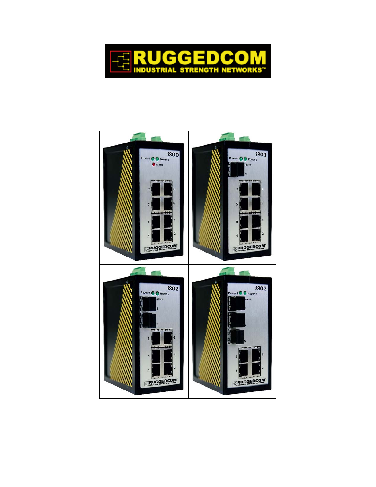
The RuggedSwitch™ i800, or i-Series, is a family of compact, fully managed
Ethernet switches designed to operate reliably in harsh industrial environments. The
flexibility of the i800 family allows the user to choose from managed or unmanaged,
regular or extended temperature, and a mix of fiber optic or copper interfaces, and
fast or Gigabit Ethernet. With up to nine Ethernet ports, the i800 is the perfect choice
for a wide variety of demanding industrial environments such as those found in
process control applications (oil and gas, petrochemical, metals and mining, wind
farms).
The i800 can be equipped with multiple fiber optic Ethernet ports for creating a fiber
optic backbone with high noise immunity and long haul connectivity. The i800 also
provides dual 24VDC power inputs for redundancy, a removable memory card for
preserving the configuration of units replaced in the field, and is packaged in a sleek,
compact, die cast aluminum enclosure that can be DIN rail mounted.
Note that despite the i800 family’s specifications, this product is not intended for
mission critical power substation applications. For equipment designed for these
environments, please visit http://www.ruggedcom.com
sales representative.
or contact a Ruggedcom
1.2 Feature Highlights
• Integrated ROS™ management (optional):
o ROSVue web server (http and https)
o ANSI menu system or Command Line Interface via ssh / telnet / serial
console
o Configuration via a single ASCII text file (transferable via TFTP or
XMODEM)
o SNMP v1, v2c, v3
o RMON remote monitoring
• Advanced layer-2 switching functions:
o Enhanced Rapid Spanning Tree (eRSTP™)
o Quality of Service (IEEE 802.1p)
o Link Aggregation (IEEE 802.3ad)
o VLAN (Virtual Local Area Network – IEEE 802.1q)
o IGMP Snooping
o Port Mirroring
• Exceeds IEC 61000-6-2 standards for industrial environments.
• Operating temperature: -20° to 60°C (-40° to 85°C optional)
• Dual, independent low-voltage power supply inputs for redundancy: 24VDC (9-
36VDC)
• Optional Form-C Failsafe output relay for critical failure or error alarming
• Full-duplex Ethernet operation (no collisions) with flow-control
• Removable microSD memory slot for configuration changes and backup,
redundant firmware storage, and enhanced logging (features pending
development)
RuggedSwitch™i800 family 5 RuggedCom®
Page 6
Product Overview
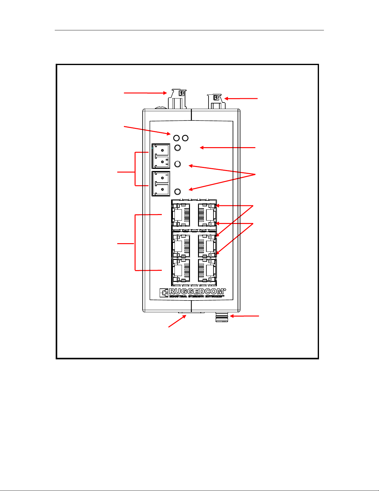
1.3 i800 Family Front Panel View
Power Connector
Power LEDs
Ports 5-7, 7&8, or 9:
10/100/1000Base Tx,
100FX, 1000SX/LX
Ports 1 – 4/6/8:
10/100 BaseTx
i802
Power 1
56
3
1
Power 2
Alarm
8
7
4
2
Fail-Safe
Relay
Alarm LED
Fiber port LEDs
Speed LEDs (top)
Link/Act LEDs
(bottom)
R
RS-232
Console Port
Memory Slot
Figure 1: Front Panel
The front panel shown is representative of the i800 family. Note that there are
several Ethernet options available in several models, outlined in Section 1.3.2,
below.
RuggedCom® 6 RuggedSwitch™i800 family
Page 7
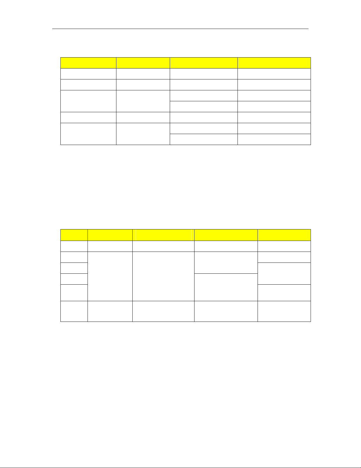
1.3.1 Front Panel LEDs
ITEM Color Activity Comments
Power status Green Solid Power On
Alarm status Red Solid Alarm condition exists
Product Overview
Fiber port status Yellow
RJ45 Speed Yellow Solid 100Mbps
RJ45 Link/Act Yellow
Table 1: Status LEDs
Blinking Link Established
Solid Tx/Rx Activity
Solid Link Established
Blinking Tx/Rx Activity
Note that the LEDs on all RJ45 Ethernet ports regardless of port orientation are
connected such that the top LED of each port is always the Speed indicator and the
bottom LED is always the Link/Activity indicator.
1.3.2 Front Panel Ethernet Options
A varied mix of Ethernet port options is available across four basic models. The basic
configuration and available options for each model are listed in Table 2, below.
Port
1 to 4 10/100Tx 10/100Tx 10/100Tx 10/100Tx
5 100FX MM/SM
6
7
8
9 Not present
i800 i801 i802 i803
10/100Tx 10/100Tx
10/100/1000Tx
1000SX MM
1000LX SM
10/100Tx
10/100/1000Tx
100FX MM/SM
1000SX MM
1000LX SM
Not present Not present
100FX MM/SM
1000SX MM
1000LX SM
Not present
Table 2: Front Panel Ethernet Options by model
For detailed Ethernet port specifications, please refer to Sections 3.5 and 3.6.
RuggedSwitch™i800 family 7 RuggedCom®
Page 8

Product Overview
r
1.4 i800 Family Top Panel View
DIN Rail
mounting
bracket
Power
Connecto
back
P1+
P1-
GND
P2-
P2+
Fail-Safe
Relay
Chassis
Ground
Ratings:
12-24V ,
, 2A
front
Figure 2: Top Panel
For details on connecting the power supplies and Ground, see Section 2.2.
For details on connecting the Fail-Safe Relay, see Section 2.3
RuggedCom® 8 RuggedSwitch™i800 family
Page 9

1.5 i800 Family Bottom Panel View
Product Overview
Ports 5-7, 7&8, or 9:
10/100/1000Base Tx,
100FX, 1000SX/LX
front
Ports 1 – 4/6/8:
10/100Base Tx
MEMORY
SLOT
Micro-SD
Memory Slot
RS-232
Console Port
CONSOLE
57600-N-8-1
DIN Rail
mounting
back
bracket
Figure 3: Bottom Panel
For details on connecting the console port, see Section 2.4.
For a description of the memory slot, see Section 2.6.
RuggedSwitch™i800 family 9 RuggedCom®
Page 10

Installation
2 Installation
2.1 DIN Rail Mounting
The i800 family of switches comes with a standard DIN rail mounting bracket. Figure
4 details the mounting configuration for a standard 1” DIN Rail.
DIN Rail
Power 1
56
i802
Power 2
Alarm
8
7
3
1
DIN Rail mounting bracket
Figure 4: DIN Rail Mounting
4
2
R
Release direction
RuggedCom® 10 RuggedSwitch™i800 family
Page 11

2.2 Power Supply Wiring and Grounding
Installation
, 2A
back
DC Input 1 DC Input 2
P1+
P1-
P2+
P2-
GND
Ratings:
12-24V ,
Chassis
Ground
Figure 5: DC Power supply and ground connections
The low voltage DC power supply features reverse polarity protection and dual
independent inputs, allowing the connection of two DC sources with the same
nominal voltage to provide redundant power supplies. A list of power and ground
connections follows in Table 3.
front
Pin Function Connector
P1+ DC Power Supply 1 positive terminal Phoenix connector
P1- DC Power Supply 1 negative terminal Phoenix connector
GND Power Supply Ground Phoenix connector
P2- DC Power Supply 2 negative terminal Phoenix connector
P2+ DC Power Supply 2 positive terminal Phoenix connector
Chassis
Ground
Table 3: Power Supply Connector Pinout
Chassis Ground connection Screw terminal on chassis
NOTE: Terminals P1-, P2-, and GND are connected together internally.
RuggedSwitch™i800 family 11 RuggedCom®
Page 12

Installation
Figure 6 illustrates the connections required for both single and dual power supply
configurations:
, 2A
P1+
P1-
P2-
P2+
P1+
P1-
P2-
GND
Ratings:
12-24V ,
GND
P2+
Ratings:
Figure 6: Power Supply Wiring Examples
NOTES:
• Connect to the DC inputs according to the polarity markings on the unit.
• Chassis Ground must be connected to the protective earth.
• The internal connection between P1-. P2-, and GND means that if two power
supplies are connected to the unit, their negative terminals must be at the same
potential.
• Equipment must be installed according to the applicable country wiring codes.
, 2A
12-24V ,
RuggedCom® 12 RuggedSwitch™i800 family
Page 13

Installation
2.3 Failsafe Output Wiring
The Failsafe output relay is provided via a Phoenix connector to signal critical error
conditions that may occur on the unit. The contacts are energized upon power up of
the unit and remain energized until a critical alarm condition or power loss occurs. A
common application for this output is to signal an alarm in the event of power failure.
12-24V ,
Ratings:
GND
front
P2-
P2+
, 2A
P1-
P1+
back
Normally Open
Common
Figure 7: Failsafe Output Relay
Pin Function
Normally Closed
Common Common relay contact
Normally Open
Table 4: Failsafe Output Relay Pinout
Normally closed (no power or critical
Normally open (no power or critical
Normally Closed
alarm condition)
alarm condition)
RuggedSwitch™i800 family 13 RuggedCom®
Page 14

Installation
2.4 RS232 Console Port Wiring
The RS232 Console Port is used for initially configuring the unit. The connection is
made using a DB9-Female to RJ45 console cable with the pin-outs listed in Table 5.
Pin 1 Pin 8
Figure 8: RS232 Female DCE pin-out
RuggedCom RS232 over RJ45 pin-out specification
Signal Name (PC is DTE) DB9- Female RJ45 Male
DCD – Carrier detect 1 2
RxD – Receive data (to DTE) 2 5
TxD – Transmit data (from DTE) 3 6
DTR – Data terminal ready 4 3
Signal GND 5 4
DSR – Data set ready 6 1*
RTS – Ready to send 7 8
CTS – Clear to send 8 7
RI – Ring Indicator 9 1*
Table 5: RS232 over RJ45 console cable pin-out
NOTE:
• This port is not intended to be a permanent connection
• The cable must be less than 2m (6.5 ft) in length.
• The following cross-connections are made inside the i800:
o DSR / RI / DTR
o RTS / CTS
• DCD is not connected.
RuggedCom® 14 RuggedSwitch™i800 family
Page 15

Installation
2.5 RJ45 Ports – Signal Description
10/100Base-TX ports allow connection to standard Category 5 (CAT-5) unshielded
twisted-pair (UTP) cable with RJ45 male connectors. The RJ45 receptacles are
directly connected to the chassis ground on the unit and can accept CAT-5 shielded
twisted-pair (STP) cables. If shielded cables are used, care must be taken to ensure
that a ground loop is not formed via the shield wire and the RJ45 receptacles at
either end. Figure 9 shows the RJ45 port pin-out.
Pin Signal
1 +Rx
2 -Rx
3 +Tx
4 Terminated
5 Terminated
6 -Tx
7 Terminated
8 Terminated
Figure 9: RJ45 Ethernet port pin-out
Case Shield (Chassis Ground)
Table 6: RJ45 Ethernet port pin-out
NOTE:
The unused pins, 4, 5, 7, and 8 are terminated to Chassis Ground via a network that
improves EMI and ESD performance.
RuggedCom does not recommend the use of copper cabling of any length for critical
real-time substation automation applications. However, transient suppression
circuitry is present on all copper ports to protect against damage from electrical
transients. This means that during a transient event, communications errors or
interruptions may occur but recovery is automatic.
RuggedCom also does not recommend using these ports to interface to field devices
across distances which could produce high levels of ground potential rise, (i.e.
greater than 2500V) during line to ground fault conditions.
RuggedSwitch™i800 family 15 RuggedCom®
Page 16

Installation
2.6 Memory Slot
The i800 family of switches feature a removable microSD memory module to support
the following features:
• Configuration update and backup
• Redundant firmware image
• Greatly expanded logging capability
• Fault-tolerant firmware update
In case of unit failure, remove power from the unit and unplug any attached network,
alarm, and console cabling. Carefully remove the memory card, observing the
following precautions:
• Power down the unit before removing the memory card.
• Do not touch the memory card contacts.
• Do not expose the memory card to extremes of temperature or humidity.
• Do not expose the memory card to large magnetic or static electric fields.
• Do not bend or drop the card.
Before applying power to a replacement unit, replace the memory card in the
replacement unit with the one taken from the failed unit. Reconnect all necessary
cabling and apply power.
WARNING:
The memory card must not be removed or replaced during normal operation.
Ensure that power is not applied to the unit when removing or inserting the
memory module.
NOTE: These features are pending and are not currently supported. The memory
card shipped with the unit will support these features as they become available.
Please contact RuggedCom for details.
RuggedCom® 16 RuggedSwitch™i800 family
Page 17

Technical Specifications
3 Technical Specifications
3.1 Type Test Specifications
IEC 61000-6-2 EMC: Generic Standards - Immunity for industrial environments
Test Description Levels
IEC 61000-4-2 ESD
IEC 61000-4-3 Radiated RFI Enclosure ports 10 V/m, 80 to 1000Mhz
IEC 61000-4-4
IEC 61000-4-5 Surge
IEC 61000-4-6
IEC 61000-4-8 Magnetic Field Enclosure ports 30 A/m @ 50, 60 Hz
IEC 61000-4-11 Voltage Dips DC Power ports 30% reduction for 0.5 period
IEC 61000-4-12 Damped Oscillatory
IEC 61000-4-16
IEC 61000-4-17
Burst (Fast
Transient)
Induced
(Conducted) RFI
Mains Frequency
Voltage
Ripple on D.C.
Power Supply
Enclosure Contact +/- 4kV
Enclosure Air +/- 8kV
Signal ports +/- 1kV @ 5kHz
DC Power ports +/- 1kV @ 5kHz
Signal ports +/- 1kV line-to-earth/line
DC Power ports
Signal ports
DC Power ports
Earth ground ports
Signal ports
DC Power ports
Signal ports
DC Power ports
DC Power ports 10%
+/- 0.5kV line-to-line
+/- 1kV line-to-earth
10V @ 0, 5-80 MHz
1kV common mode
0.5kV differential mode
10V continuous
100V for 1s
Table 7: Electromagnetic Compatibility tests
IEC Environmental Type Tests
Test Description Test Levels
IEC 60068-2-1 Cold Temperature Test Ad -40°C, 16 Hours
IEC 60068-2-2 Dry Heat Test Bd +85°C, 16 Hours
IEC 60068-2-30
IEC 60255-21-1 Vibration Tests Fc 1g @ (10 - 500) Hz
IEC 60255-21-2 Shock Tests Ea 30g @ 11mS
Table 8: Environmental Type Tests
Humidity (Damp
Heat, Cyclic)
Test Db
95% (non-condensing), 55°C , 6
cycles
RuggedSwitch™i800 family 17 RuggedCom®
Page 18

Technical Specifications
3.2 Environmental Specifications
Parameter Range Comments
Ambient Operating
Temperature
Ambient Storage
Temperature
Ambient Relative
Humidity
Vibration 1g (10-500Hz)
Shock 30g 11ms
Table 9: Environmental Specifications
-20 to 60°C
-40 to 85°C (Optional)
-40 to 85°C
up to 95%
Ambient Temperature as measured from
a 30 cm radius surrounding the center of
3.3 Power Supply Specifications
the enclosure.
Non-condensing, 55°C, 6 cycles
Power Supply
Type
24 VDC 9 VDC 36 VDC 3A (T) 9W
Table 10: Power Supply Specifications
Minimum
Input
Maximum
Input
Fuse
Rating
Maximum
Power
Consumption
NOTES:
• (T) denotes a time-delay fuse
• For continued protection against risk of fire, replace only with same type and
rating of fuse.
3.4 Failsafe Relay Specifications
Parameter Value
Max Switching Voltage 30VAC, 80VDC
Rated Switching Current
Table 11: Failsafe Relay Specification
NOTES:
• Resistive Load.
• For Class-2 circuits only.
1A @ 30VDC, 0.3A @ 80VDC
0.3A @ 30VAC
Isolation Comments
1500 V
Table 12: Failsafe Relay Isolation
Dielectric test voltage (1 minute) between coil & contacts
rms
RuggedCom® 18 RuggedSwitch™i800 family
Page 19

Technical Specifications
3.5 RJ45 Ethernet Port Specifications
Data Port Media Distance Connector Type
10/100 Mbps CAT-5 UTP or STP 100m RJ45
Table 13: RJ45 Ethernet Port Specifications
3.6 Fiber Optic Port Specifications
Order
Code
_FG01 1000SX MM/LC 850 62.5/125
_FG03 1000LX SM/LC 1310 9/125
_FX11 100FX MM/LC 1310 62.5/125
_FX06 100FX SM/LC 1300 9/125
Table 14: Fiber Optic Port Specifications
Order
Code
_FG01 -9.5 -4.0 -20 0.0 0.4 10.5
_FG03 -9.5 -3.0 -21 -3.0 10 11.5
_FX11 -19 -14 -32 -14 2 13
_FX06 -15 -8.0 -38 -3.0 20 23
Table 15: Fiber Optic Port Specifications (continued)
Speed
Standard
Tx min
(dBm)
Connector
Tx max
(dBm)
Mode /
Tx (nm)
Rx
Sensitivity
(dBm)
Cable Type
(um)
Rx
Saturation
(dBm)
Typical
Distance (km)
Power
Budget
(dB)
NOTES:
• All values listed are average values
• To convert from average to peak add 3 dBm. To convert from peak to average,
subtract 3 dBm.
• Maximum segment length is greatly dependent on factors such as fiber quality,
and number of patches and splices. Please consult RuggedCom sales
associates when determining maximum segment distances.
RuggedSwitch™i800 family 19 RuggedCom®
Page 20

Technical Specifications
3.7 Physical Dimensions
5.296
4.625
Power 1
Power 2
Alarm
8
7
56
3
1
2.225
MEMORY
SLOT
4
2
R
i802
4.421
3.833
0.833
0.246
0.460
3.050
3.750
3.918
3.490
3.918
CONSOLE
57600-N-8-1
NOTE: All dimensions are in inches.
Figure 10: Mechanical Specifications
Parameter Value Comments
Dimensions
4.625 x 2.25 x 3.75 inches
(117 x 57 x 95 mm)
(height x width x depth)
Weight 1.5 lb (0.68 Kg)
Enclosure Die cast Aluminum
Table 16: Physical Dimensions
RuggedCom® 20 RuggedSwitch™i800 family
Page 21

3.8 Agency Approvals
Agency Standards Comments Status
ATEX Zone 2
FCC FCC Part 15, Class A Emissions Approved
Gas, Vapor, or Dust
environmental
Pending
Warranty
EN/CISPR
FDA/CDRH
ISO ISO9001:2000
cUL
cUL
Table 17: Agency Approvals
EN55022 (CISPR22), Class
A
21 CFR Chapter 1,
Subchapter J
cUL1604 (Class 1, Division
2)
cUL508 (UL508/CDA C22,
EN61010-1)
Emissions Approved
Laser Eye Safety Pending
Design and
manufacturing
process
Hazardous Location Pending
Safety Pending
Certified quality program
4 Warranty
RuggedCom warrants this product for a period of five (5) years from date of
purchase. For warranty details, visit http://www.ruggedcom.com
customer service representative. Should this product require warranty or service
contact the factory at:
RuggedCom Inc.
30 Whitmore Road,
Woodbridge, Ontario
Canada L4L 7Z4
or contact your
Phone: (905) 856-5288
Fax: (905) 856-1995
Warranty Exclusion: The i800 (“i-Series”) product line is not intended for nor shall they be used for or
as part of any activity or process involving electric utility substation applications. Should these products
be used for electric utility substation applications, the following applies: (i) product performance is not
guaranteed; (ii) the manufacturers warranty will not be applicable (i.e. it will be voided and technical
support will not be provided) and (iii) RuggedCom will not accept any liabilities as a result of
performance issues.
RuggedSwitch™i800 family 21 RuggedCom®
 Loading...