

Page 1

SmartCell Gateway 200/Virtual SmartZone
High-Scale for Release 3.4.1
Administrator Guide
Part Number: 800-71377-001
Published: 31 January 2017
Page 2

Contents
Copyright Notice and Proprietary Information
Document Conventions
Documentation Feedback
Online Training Resources
1 Navigating the Web Interface
Setting Up the Controller for the First Time..................................................................19
Logging On to the Web Interface.................................................................................19
Web Interface Features...............................................................................................20
Main Menu........................................................................................................21
Submenu..........................................................................................................22
Sidebar..............................................................................................................22
Content Area.....................................................................................................22
Miscellaneous Bar.............................................................................................22
Using Widgets on the Dashboard................................................................................23
Widgets That You Can Display..........................................................................23
Widget Slots......................................................................................................24
Adding a Widget................................................................................................25
Adding a Widget to a Widget Slot......................................................................26
Displaying a Widget in a Widget Slot..................................................................27
Moving a Widget...............................................................................................28
Deleting a Widget..............................................................................................28
Changing the Administrator Password.........................................................................29
Logging Off the Web Interface.....................................................................................30
2 Managing Ruckus Wireless AP Zones
Working with AP Zones...............................................................................................31
Using the Domain Tree......................................................................................31
Creating an AP Zone.........................................................................................32
Cloning an AP Zone from the Domain Tree........................................................42
Cloning an AP Zone from the AP Zone List........................................................42
Viewing Existing AP Zones.................................................................................43
Viewing the AP Zone Configuration....................................................................43
Deleting an AP Zone..........................................................................................44
SmartCell Gateway 200/Virtual SmartZone High-Scale for Release 3.4.1 Administrator Guide
2
Page 3

Working with AP Groups.............................................................................................45
Creating an AP Group.......................................................................................45
Working with AAA Servers...........................................................................................55
Creating an AAA Server.....................................................................................55
Testing an AAA Server.......................................................................................57
Deleting an AAA Server.....................................................................................58
Working with Hotspot (WISPr) Portals..........................................................................58
Creating a Hotspot Portal..................................................................................59
Deleting a Hotspot Portal...................................................................................61
Working with Guest Access Portals.............................................................................62
Creating a Guest Access Portal.........................................................................62
Viewing Guest Access Portals...........................................................................63
Deleting Guest Access Portals...........................................................................64
Working with Web Authentication Portals....................................................................64
Adding an AAA Server for the Web Authentication Portal...................................65
Creating a Web Authentication Portal................................................................65
Creating a WLAN for the Web Authentication Portal..........................................66
Working with Hotspot 2.0 Services..............................................................................67
Working with WLANs and WLAN Groups....................................................................68
Creating a WLAN...............................................................................................68
Working with WLAN Groups..............................................................................80
Working with WLAN Schedules...................................................................................83
Creating a WLAN Schedule Profile.....................................................................83
Working with Device Policies.......................................................................................84
Creating a Device Access Policy........................................................................85
Viewing Device Access Policies.........................................................................86
Deleting Device Access Policies.........................................................................86
Working with L2 Access Control Policies.....................................................................87
Creating an L2 Access Policy............................................................................87
Viewing L2 Access Policies................................................................................88
Deleting L2 Access Policies...............................................................................88
Working with Bonjour Policies.....................................................................................89
Creating a Bonjour Gateway Rule on the AP......................................................89
Applying a Bonjour Policy to an AP....................................................................91
Creating a DiffServ Profile............................................................................................92
Creating an Ethernet Port Profile.................................................................................93
Important Notes About Ethernet Port Profiles....................................................96
Working With Dynamic PSKs.......................................................................................97
Viewing Dynamic PSKs......................................................................................97
SmartCell Gateway 200/Virtual SmartZone High-Scale for Release 3.4.1 Administrator Guide
3
Page 4

Generating Dynamic PSKs................................................................................98
Importing Dynamic PSKs...................................................................................98
3 Managing Global Configuration, AP Tunnel Profiles, Templates,
and AP Registration Rules
Managing Global Configuration.................................................................................101
Creating AP Tunnel Profiles.......................................................................................102
Creating a Ruckus GRE Tunnel Profile.............................................................102
Creating a SoftGRE Tunnel Profile...................................................................103
Creating an IPsec Profile..................................................................................104
Working with Zone Templates...................................................................................110
Creating and Configuring a Zone Template......................................................111
Exporting a Zone Template..............................................................................122
Importing a Zone Template..............................................................................122
Deleting a Zone Template................................................................................123
Working with WLAN Templates.................................................................................123
Creating and Configuring a WLAN Template....................................................124
Viewing Existing WLAN Templates...................................................................133
Deleting WLAN Templates...............................................................................133
Working with Registration Rules................................................................................134
Creating a Registration Rule............................................................................134
Configuring Registration Rule Priorities............................................................136
Deleting a Registration Rule.............................................................................136
4 Working with 3rd Party AP Zones
3rd Party AP Zone Types..........................................................................................138
Adding a 3rd Party AP Zone......................................................................................139
Viewing Existing 3rd Party AP Zones.........................................................................141
Deleting a 3rd Party AP Zone....................................................................................142
5 Managing Access Points
Overview of Access Point Configuration....................................................................143
Viewing Managed Access Points...............................................................................143
Provisioning and Swapping Access Points................................................................144
Options for Provisioning and Swapping APs....................................................145
Understanding How Swapping Works.............................................................146
Editing AP Configuration............................................................................................146
SmartCell Gateway 200/Virtual SmartZone High-Scale for Release 3.4.1 Administrator Guide
4
Page 5

Editing Swap Configuration.......................................................................................147
Moving a Single Access Point to a Different AP Zone................................................148
Moving Multiple Access Points to a Different AP Zone...............................................149
Deleting an Access Point...........................................................................................149
6 Configuring Services and Profiles
Configuring the GGSN/PGW Service.........................................................................151
Configuring Authentication Services..........................................................................153
Adding an Authentication Service....................................................................153
Testing the AAA Server Configuration..............................................................156
Viewing RADIUS Services................................................................................158
Deleting a Single RADIUS Service....................................................................158
Deleting Multiple RADIUS Services..................................................................159
Configuring HLR Services..........................................................................................159
Map Gateway Settings....................................................................................159
MNC to NDC Mapping....................................................................................160
Configuring Diameter Services...................................................................................163
Configuring System Wide Settings...................................................................163
Configuring Remote Peer Settings...................................................................164
Configuring FTP Services..........................................................................................165
Important Notes When Adding FTP Servers.....................................................166
Configuring Location Services...................................................................................167
Adding an LBS Server.....................................................................................167
Configuring the Controller to Use the LBS Server............................................168
Configuring an SMS Server.......................................................................................170
Working with Profiles.................................................................................................171
Working with Authentication Profiles................................................................171
Working with Accounting Profiles.....................................................................175
Working with Hotspot Profiles..........................................................................177
Working with Network Traffic Profiles...............................................................182
Working with User Traffic Profiles.....................................................................185
Working with DNS Server Services..................................................................188
Working with Forwarding Profiles.....................................................................189
7 Configuring the System Settings
Overview of the System Settings...............................................................................203
Configuring General System Settings........................................................................203
Setting the System Time..................................................................................203
SmartCell Gateway 200/Virtual SmartZone High-Scale for Release 3.4.1 Administrator Guide
5
Page 6

Configuring the Syslog Server Settings............................................................204
Configuring the Northbound Portal Interface....................................................207
Configuring the SMTP Server Settings.............................................................207
Configuring the FTP Server Settings................................................................208
Setting Critical AP Auto Tagging Rules............................................................209
Configuring Q-in-Q Ether Type........................................................................210
Managing the Global User Agent Black List.....................................................210
Configuring SCI Settings..................................................................................211
Enabling and Configuring Node Affinity............................................................212
Managing the Certificate Store.........................................................................213
Configuring Advanced Gateway Options.........................................................218
Configuring Cluster Planes........................................................................................219
Setting the System IP Mode............................................................................220
Rebalancing APs Across Nodes......................................................................221
Configuring Control Planes..............................................................................222
Configuring a Data Plane.................................................................................226
Configuring Cluster Redundancy.....................................................................229
Rehoming Managed APs.................................................................................232
Configuring Network Management............................................................................232
Configuring the SNMPv2 and SNMPv3 Agents................................................232
Sending SNMP Traps and Email Notifications for Events.................................236
Configuring Event Thresholds..........................................................................238
Controlling Access to the Management Interfaces...........................................240
Configuring Hosted AAA Services.............................................................................241
EAP-SIM Configuration....................................................................................242
EAP-AKA Configuration...................................................................................243
8 Working with Management Domains
Overview of Management Domains...........................................................................245
Viewing a List of Management Domains....................................................................245
Creating a New Management Domain.......................................................................246
Deleting a Management Domain................................................................................247
Assigning an Administrator Account to a Role...........................................................247
9 Managing Administrator Accounts
Overview of Administrator Accounts and Roles.........................................................250
Viewing a List of Administrator Accounts, Roles, and RADIUS Servers......................250
Creating an Administrator Account............................................................................252
SmartCell Gateway 200/Virtual SmartZone High-Scale for Release 3.4.1 Administrator Guide
6
Page 7

Creating a New Administrator Role............................................................................252
Editing an Administrator Role....................................................................................253
Cloning an Existing Administrator Role......................................................................254
Adding a RADIUS Server for Administrators..............................................................254
About TACACS+ Support................................................................................255
Using a Backup RADIUS Server................................................................................256
Testing an AAA Server...............................................................................................259
Deleting an Administrator Account, Role, or RADIUS Server......................................260
10 Managing Mobile Virtual Network Operator Accounts
Overview of Mobile Virtual Network Operator Accounts.............................................261
Viewing a List of MVNOs...........................................................................................261
Creating a New MVNO Account................................................................................262
Using a Backup RADIUS Server for Authorizing and Authenticating MVNOs..............265
Editing an MVNO Account.........................................................................................265
Deleting an MVNO Account.......................................................................................266
11 Creating and Managing Hotspots
Overview of Hotspot Management............................................................................267
Hotspot Terminologies..............................................................................................267
How Hotspot Authentication Works...........................................................................268
Call Flow for Devices That Use a Web Proxy.............................................................271
Devices Using a Static Web Proxy...................................................................273
Devices Using a Dynamic Web Proxy..............................................................274
User Agent Blacklist..................................................................................................274
Notes on Using iOS Devices to Access the Hotspot..................................................275
Notes on Using Amazon Kindle Fire to Access the Hotspot.......................................275
What You Will Need..................................................................................................276
Hotspot Configuration Options..................................................................................276
Why Create a User Defined Interface...............................................................276
Creating a User Defined Interface....................................................................277
Adding a RADIUS Server to the Controller.......................................................278
Creating a Hotspot WLAN...............................................................................279
Creating a WLAN.............................................................................................280
Downloading Captive Portal and Subscriber Portal Logs...........................................281
12 Monitoring AP Zones, Access Points, and Wireless Clients
SmartCell Gateway 200/Virtual SmartZone High-Scale for Release 3.4.1 Administrator Guide
7
Page 8

Monitoring AP Zones.................................................................................................283
Viewing a Summary of AP Zones.....................................................................283
Exporting the AP Zone List to CSV..................................................................285
Viewing the Configuration of an AP Zone.........................................................286
Viewing All APs That Belong to an AP Zone on Google Maps..........................287
Monitoring Managed Access Points..........................................................................287
Viewing a Summary of Access Points..............................................................287
Exporting the Access Point List to CSV...........................................................290
Viewing the Configuration of an Access Point..................................................290
Downloading the Support Log from an Access Point.......................................291
Restarting an Access Point Remotely..............................................................292
Running Ping and Traceroute on an Access Point...........................................293
Monitoring Wireless Clients........................................................................................294
Viewing a Summary of Wireless Clients............................................................294
Exporting the Wireless Client List to CSV.........................................................296
Viewing Information About a Wireless Client....................................................297
Measuring Wireless Network Throughput with SpeedFlex................................298
13 Monitoring the System, Alarms, Events, and Administrator
Activity
Monitoring the Controller System..............................................................................300
Viewing the System Cluster Overview...........................................................300
Displaying the Chassis View of Cluster Nodes.................................................301
Starting the Cluster Real-time Monitor..........................................................302
Monitoring Rogue Access Points...............................................................................303
Viewing Alarms..........................................................................................................304
Using the Search Criteria Section....................................................................305
Exporting the Alarm List to CSV.......................................................................306
Clearing Alarms...............................................................................................307
Acknowledging Alarms....................................................................................307
Viewing Events..........................................................................................................307
Using the Search Criteria Section..................................................................309
Exporting the Event List to CSV.......................................................................310
Viewing Administrator Activity....................................................................................311
Using the Search Criteria Section....................................................................312
Exporting the Administrator Activity List to CSV...............................................313
SmartCell Gateway 200/Virtual SmartZone High-Scale for Release 3.4.1 Administrator Guide
8
Page 9

14 Working with Reports
Types of Reports.......................................................................................................315
Active TTG Sessions Report............................................................................315
Client Number Report......................................................................................315
Client Number vs Airtime Report......................................................................315
Continuously Disconnected APs Report..........................................................316
Failed Client Associations Report.....................................................................316
New Client Associations Report.......................................................................316
System Resource Utilization Report.................................................................316
TX/RX Bytes Report.........................................................................................316
Creating a New Report..............................................................................................316
Step 1: Define the General Report Details........................................................317
Step 2: Define the Resource Filter Criteria........................................................317
Step 3: Define the Time Filter...........................................................................318
Step 4: Define the Report Generation Schedule...............................................319
Step 5: Enable Email Notifications (Optional)....................................................319
Step 6: Export the Report to an FTP Server (Optional).....................................320
Step 7: Save the Report..................................................................................320
Viewing a List of Existing Reports..............................................................................320
Deleting a Report......................................................................................................321
15 Working with Local, Guest, and Remote Users
Working with Local, Guest, and Remote Users..........................................................322
Working with Local Users................................................................................322
Working with Guest Users...............................................................................324
Working with User Roles...........................................................................................337
Creating a User Role.......................................................................................337
Managing Subscription Packages.............................................................................337
Viewing a List of Subscription Packages..........................................................338
Creating a Subscription Package.....................................................................338
Editing a Subscription Package.......................................................................339
Deleting a Subscription Package.....................................................................340
16 Performing Administrative Tasks
Backing Up and Restoring Clusters...........................................................................341
Creating a Cluster Backup...............................................................................341
SmartCell Gateway 200/Virtual SmartZone High-Scale for Release 3.4.1 Administrator Guide
9
Page 10

Restoring a Cluster Backup.............................................................................342
Deleting a Cluster Backup...............................................................................344
Backing Up and Restoring the Controller's Network Configuration from an FTP
Server...................................................................................................................345
Backing Up to an FTP Server..........................................................................345
Restoring from an FTP Server..........................................................................347
Backing Up and Restoring System Configuration......................................................352
Creating a System Configuration Backup........................................................352
Exporting the Configuration Backup to an FTP Server Automatically................353
Scheduling a Configuration Backup.................................................................354
Downloading a Copy of the Configuration Backup...........................................355
Restoring a System Configuration Backup.......................................................356
Deleting a Configuration Backup......................................................................357
Resetting a Node to Factory Settings........................................................................358
What Happens After Reset to Factory Settings................................................358
Using the Web Interface..................................................................................358
Using the CLI...................................................................................................359
Upgrading the Controller...........................................................................................360
Performing the Upgrade..................................................................................360
Verifying the Upgrade......................................................................................364
Rolling Back to a Previous Software Version....................................................364
Recovering a Cluster from an Unsuccessful Upgrade......................................365
Uploading AP Patch Files..........................................................................................366
Working with Logs.....................................................................................................367
Available System Log Types............................................................................367
Downloading All Logs......................................................................................369
Downloading Snapshot Logs Generated from the CLI.....................................370
Managing AP Certificate Replacement.......................................................................371
Viewing AP Certificate Status ..........................................................................372
Exporting AP Certificate Requests...................................................................372
Requesting AP Certificate Renewal..................................................................374
Importing AP Certificate Responses................................................................375
Confirming AP Certification Status...................................................................378
Managing Licenses...................................................................................................379
Default Licenses..............................................................................................380
Viewing Installed Licenses...............................................................................381
Viewing License Summary...............................................................................381
Configuring the License Server........................................................................382
Importing License Files....................................................................................383
SmartCell Gateway 200/Virtual SmartZone High-Scale for Release 3.4.1 Administrator Guide
10
Page 11

Downloading Licenses.....................................................................................384
Synchronizing Controller with the License Server.............................................385
Appendix A: Overview of the Captive Portal
Configuring the Captive Portal...................................................................................387
Configuring the GGSN/PGW Service...............................................................387
Configuring an Authentication Profile...............................................................389
Configuring an Accounting Profile....................................................................392
Configuring TTG+PDG Forwarding Profiles......................................................394
Configuring the WISPr (Hotspot) Services of an AP Zone.................................396
AP Zone WLAN Services & Group...................................................................398
Captive Portal Workflows and VSA............................................................................401
Successful Captive Portal Authentication.........................................................401
Successful GTP Tunnel Establishment.............................................................402
Ruckus Wireless VSAs for the Captive Portal...................................................403
Appendix B: Statistics Files the Controller Exports to an FTP Server
AP Inventory..............................................................................................................405
Control Plane Statistics....................................................................................408
Mobility Zone Inventory....................................................................................408
Zone Statistics.................................................................................................409
AP Statistics....................................................................................................410
Zone Time Radio Statistics..............................................................................411
Zone Time WLAN Statistics.............................................................................412
AP Time Radio Statistics.................................................................................413
AP Time WLAN Statistics................................................................................414
Control Plane Statistics....................................................................................415
Data Plane Statistics........................................................................................420
Data Plane Ethernet Port Statistics..................................................................420
AP SoftGRE Tunnel Statistics..........................................................................421
SoftGRE Gateway Statistics............................................................................422
Tenant Time Radio Statistics...........................................................................423
Tenant Time WLAN Statistics..........................................................................424
Tenant Zone Statistics.....................................................................................425
Tenant Zone Radio Statistics...........................................................................427
Tenant Inventory File........................................................................................428
SmartCell Gateway 200/Virtual SmartZone High-Scale for Release 3.4.1 Administrator Guide
11
Page 12

Appendix C: AP-SCG/SZ/vSZ/vSZ-D Communication
Appendix D: SoftGRE Support
Overview of SoftGRE Support...................................................................................434
Supported Deployment Scenario.....................................................................434
SoftGRE Packet Format..................................................................................435
Configuring SoftGRE.......................................................................................436
Monitoring SoftGRE.........................................................................................437
SoftGRE SNMP MIBs......................................................................................439
SoftGRE Alarms and Events............................................................................439
Appendix E: Replacing Hardware Components
Installing or Replacing Hard Disk Drives.....................................................................443
Ordering a Replacement Hard Disk.................................................................443
Removing the Front Bezel................................................................................443
Removing an HDD Carrier from the Chassis....................................................444
Installing a Hard Drive in a Carrier....................................................................445
Reinstalling the Front Bezel..............................................................................448
Replacing PSUs..............................................................................................449
Replacing System Fans...................................................................................449
Appendix F: Replacing a Controller Node
Backing Up and Restoring the Cluster.......................................................................452
Step 1: Back Up the Cluster from the Web Interface........................................452
Step 2: Back Up the Cluster from the Controller CLI........................................452
Step 3: Transfer the Cluster Backup File to an FTP Server...............................453
Step 4: Restoring the Cluster Backup to the Controller....................................454
Backing Up and Restoring Configuration...................................................................457
Backed Up Configuration Information..............................................................457
Backing Up Configuration................................................................................458
Restoring Configuration...................................................................................458
Appendix G: SCG SSID Syntax
SSIDs Supported in Release 1.1.x.............................................................................462
SSIDs Supported in Release 2.1.x.............................................................................463
SmartCell Gateway 200/Virtual SmartZone High-Scale for Release 3.4.1 Administrator Guide
12
Page 13

SSIDs Supported in Release 2.5.x.............................................................................463
SSIDs Supported in Release 3.0 and Above..............................................................464
ZoneDirector SSID Syntax.........................................................................................464
SSIDs Supported in Releases 9.8 and 9.7.......................................................464
Supported SSIDs in ZoneFlex Release 9.6.......................................................465
ZoneFlex AP SSID Syntax.........................................................................................465
Supported SSIDs in Releases 9.8, 9.7, and 9.6...............................................465
SmartCell Gateway 200/Virtual SmartZone High-Scale for Release 3.4.1 Administrator Guide
13
Page 14

Copyright Notice and Proprietary Information
Copyright Notice and Proprietary Information
Copyright 2016. Ruckus Wireless, Inc. All rights reserved.
No part of this documentation may be used, reproduced, transmitted, or translated, in any form
or by any means, electronic, mechanical, manual, optical, or otherwise, without prior written
permission of Ruckus Wireless, Inc. (“Ruckus”), or as expressly provided by under license from
Ruckus.
Destination Control Statement
Technical data contained in this publication may be subject to the export control laws of the
United States of America. Disclosure to nationals of other countries contrary to United States
law is prohibited. It is the reader’s responsibility to determine the applicable regulations and to
comply with them.
Disclaimer
THIS DOCUMENTATION AND ALL INFORMATION CONTAINED HEREIN (“MATERIAL”) IS
PROVIDED FOR GENERAL INFORMATION PURPOSES ONLY. RUCKUS AND ITS LICENSORS
MAKE NO WARRANTY OF ANY KIND, EXPRESS OR IMPLIED, WITH REGARD TO THE
MATERIAL, INCLUDING, BUT NOT LIMITED TO, THE IMPLIED WARRANTIES OF
MERCHANTABILITY, NON-INFRINGEMENT AND FITNESS FOR A PARTICULAR PURPOSE,
OR THAT THE MATERIAL IS ERROR-FREE, ACCURATE OR RELIABLE. RUCKUS RESERVES
THE RIGHT TO MAKE CHANGES OR UPDATES TO THE MATERIAL AT ANY TIME.
Limitation of Liability
IN NO EVENT SHALL RUCKUS BE LIABLE FOR ANY DIRECT, INDIRECT, INCIDENTAL, SPECIAL
OR CONSEQUENTIAL DAMAGES, OR DAMAGES FOR LOSS OF PROFITS, REVENUE, DATA
OR USE, INCURRED BY YOU OR ANY THIRD PARTY, WHETHER IN AN ACTION IN CONTRACT
OR TORT, ARISING FROM YOUR ACCESS TO, OR USE OF, THE MATERIAL.
Trademarks
Ruckus Wireless, Ruckus, the bark logo, BeamFlex, ChannelFly, Dynamic PSK, FlexMaster,
Simply Better Wireless, SmartCell, SmartMesh, SmartZone, Unleashed, ZoneDirector and
ZoneFlex are trademarks of Ruckus Wireless, Inc. in the United States and other countries. All
other product or company names may be trademarks of their respective owners.
SmartCell Gateway 200/Virtual SmartZone High-Scale for Release 3.4.1 Administrator Guide
14
Page 15
Document Conventions
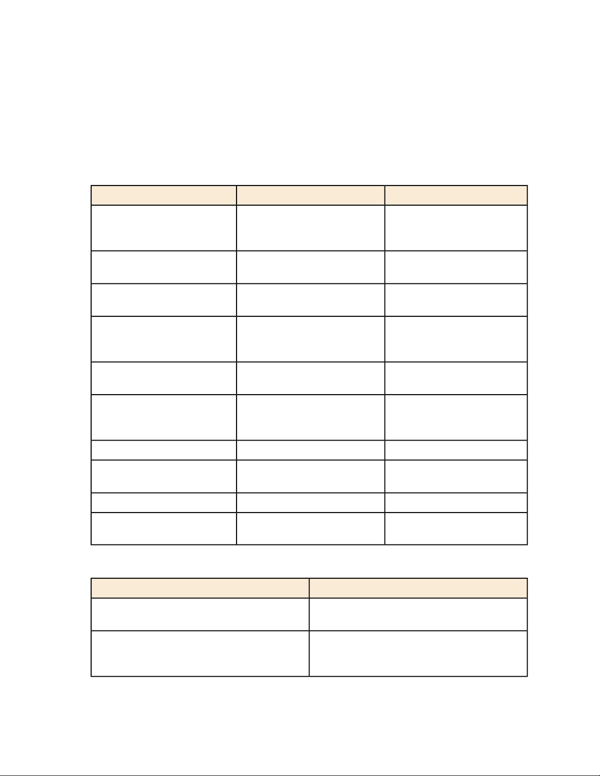
Table 1: Text conventions on page 15 and Table 2: Notice conventions on page 15 list the text
and notice conventions that are used throughout this guide.
Table 1: Text conventions
ExampleDescriptionConvention
15
message phrase
user input
user interface controls
Start > All Programs
ctrl+V
screen or page names
parameter name
displayed in response to a
command or a status
Represents information that you
enter
buttons, and field names
commands, or menus and
submenus
Represents keyboard keys
pressed in combination
Represents CLI commandscommand name
Represents a parameter in a
CLI command or UI feature
[Device Name] >Represents messages
[Device Name] > set
ipaddr 10.0.0.12
Click Create NewKeyboard keys, software
Select Start > All ProgramsRepresents a series of
Press ctrl+V to paste the text
from the clipboard.
Click Advanced Settings. The
Advanced Settings page
appears.
filepath
strings
Table 2: Notice conventions
DescriptionNotice type
NOTE:
CAUTION:
SmartCell Gateway 200/Virtual SmartZone High-Scale for Release 3.4.1 Administrator Guide
Information that describes important features
or instructions
Information that alerts you to potential loss of
data or potential damage to an application,
system, or device
{ZoneDirectorID}Represents variable datavariable name
http://ruckuswireless.comRepresents file names or URI
15
Page 16

Document Conventions
DescriptionNotice type
WARNING:
Information that alerts you to potential personal
injury
SmartCell Gateway 200/Virtual SmartZone High-Scale for Release 3.4.1 Administrator Guide
16
Page 17

Documentation Feedback
Ruckus Wireless is interested in improving its documentation and welcomes your comments
and suggestions.
You can email your comments to Ruckus Wireless at: docs@ruckuswireless.com
When contacting us, please include the following information:
• Document title
• Document part number (on the cover page)
• Page number (if appropriate)
17
SmartCell Gateway 200/Virtual SmartZone High-Scale for Release 3.4.1 Administrator Guide
17
Page 18

Online Training Resources
Online Training Resources
To access a variety of online Ruckus Wireless training modules, including free introductory
courses to wireless networking essentials, site surveys, and Ruckus Wireless products, visit the
Ruckus Wireless Training Portal at:
https://training.ruckuswireless.com.
SmartCell Gateway 200/Virtual SmartZone High-Scale for Release 3.4.1 Administrator Guide
18
Page 19

19
Navigating the Web Interface
In this chapter:
• Setting Up the Controller for the First Time
• Logging On to the Web Interface
• Web Interface Features
• Using Widgets on the Dashboard
• Changing the Administrator Password
• Logging Off the Web Interface
In this chapter:
NOTE: Before continuing, make sure that you have already set up the controller on the network as
described in the Getting Started Guide or Quick Setup Guide for your controller platform.
Some of the new features (for example, location based services, rogue AP detection, force DHCP,
and others) that this guide describes may not be visible on the controller web interface if the AP
firmware deployed to the zone you are configuring is earlier than this release. To ensure that you can
view and configure all new features that are available in this release, Ruckus Wireless recommends
upgrading the AP firmware to the latest version.
1
Setting Up the Controller for the First Time
For information on how to set up the controller for the first time, including instructions for running
and completing the controller's Setup Wizard, see the Getting Started Guide or Quick Setup
Guide for your controller platform.
Logging On to the Web Interface
Before you can log on to the controller web interface, you must have the IP address that you
assigned to the Management (Web) interface when you set up the controller on the network
using the Setup Wizard.
Once you have this IP address, you can access the web interface on any computer that can
reach the Management (Web) interface on the IP network.
Follow these steps to log on to the controller web interface.
1. On a computer that is on the same subnet as the Management (Web) interface, start a web
browser. Supported web browsers include:
• Google Chrome 15 (and later) - recommended
• Microsoft Internet Explorer 9.0
• Safari 5.1.1 (and later)
SmartCell Gateway 200/Virtual SmartZone High-Scale for Release 3.4.1 Administrator Guide
19
Page 20
Navigating the Web Interface
Web Interface Features
• Mozilla Firefox 8 (and later)
2. In the address bar, type the IP address that you assigned to the Management (Web) interface,
and then append a colon and 8443 (the controller's management port number) at the end
of the address.
For example, if the IP address that you assigned to the Management (Web) interface is
10.10.101.1, then you should enter: https://10.10.101.1:8443
NOTE: The controller web interface requires an HTTPS connection. You must append https
(not http) to the management interface IP address to connect to the web interface. If a
browser security warning appears, this is because the default SSL certificate (or security
certificate) that the controller is using for HTTPS communication is signed by Ruckus Wireless
and is not recognized by most web browsers.
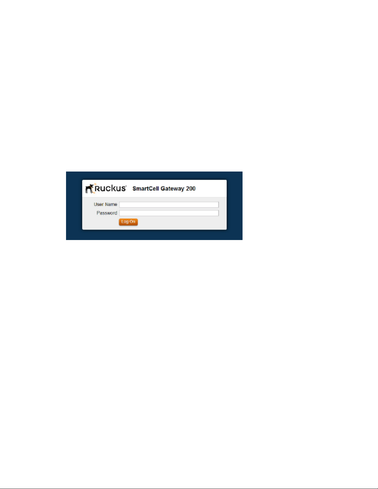
The controller web interface logon page appears.
Figure 1: The controller’s logon page
3. Log on to the controller web interface using the following logon details:
• User Name: admin
• Password: {the password that you set when you ran the Setup Wizard}
4. Click Log On.
The web interface refreshes, and then displays the Dashboard, which indicates that you have
logged on successfully.
Web Interface Features
Use the web interface to manage the controller and the APs that provide wireless service to
users on the network.
The web interface (shown in Figure 2: The controller web interface features on page 21) is the
primary interface that you will use to:
• Manage AP zones, access points, and management domains
• Create and manage administrator and mobile virtual network operator accounts
• Monitor AP zones, managed access points, wireless clients
• View alarms, events, and administrator activity
SmartCell Gateway 200/Virtual SmartZone High-Scale for Release 3.4.1 Administrator Guide
20
Page 21
Navigating the Web Interface
Web Interface Features
• Generate reports
• Perform administrative tasks, including backing up and restoring system configuration,
upgrading the cluster upgrade, downloading support logs, performing system diagnostic
tests, viewing the statuses of controller processes, and uploading additional licenses (among
others)
• Configure services and profiles for different network elements, packages, and configurations
specific to the controller.
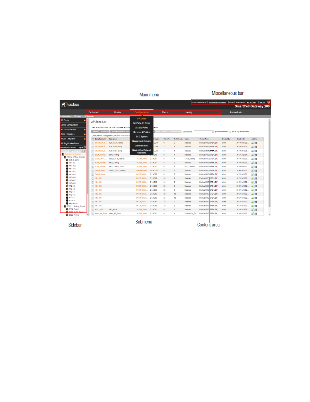
Figure 2: The controller web interface features
The following sections describe the web interface features that are called out in Figure 2: The
controller web interface features on page 21:
Main Menu
This is the primary navigation menu. The main menu contains six items:
• Monitor: Contains options for viewing information about AP zones, access points, wireless
clients, system information, alarms, events, and administrator activity.
For more information, see the following topics:
• Monitoring AP Zones, Access Points, and Wireless Clients on page 283
• Monitoring the System, Alarms, Events, and Administrator Activity on page 300
• Configuration: Contains options for managing AP zones, access points, system settings,
management domains, administrator accounts and mobile virtual network administrator
accounts.
For more information, see the following topics:
SmartCell Gateway 200/Virtual SmartZone High-Scale for Release 3.4.1 Administrator Guide
21
Page 22

Navigating the Web Interface
Web Interface Features
• Managing Ruckus Wireless AP Zones on page 31
• Managing Access Points on page 143
• Configuring Services and Profiles on page 151
• Configuring the System Settings on page 203
• Working with Management Domains on page 245
• Managing Administrator Accounts on page 250
• Managing Mobile Virtual Network Operator Accounts on page 261
• Report: Contains options for generating various types of reports, including network tunnel
statistics and historical client statistics. For more information, see Working with Reports on
page 315.
• Identity: Contains options for creating and managing profiles and guest passes. For more
information, see Working with Local, Guest, and Remote Users on page 322.
• Administration: Contains options for performing administrative tasks, such as backing up
and restoring the database, upgrading the system, downloading log files, and performing
diagnostic tests. For more information, see Performing Administrative Tasks on page 341.
Submenu
The submenu appears when you hover the mouse pointer over the Main Menu on page 21
items. The submenu provides options related to the main menu item on which you hovered your
mouse pointer.
For example, submenu items under the Configuration menu include options for configuring AP
zones and access points.
Sidebar
The sidebar, located on the left side of the Content Area on page 22, provides additional options
related to the submenu that you clicked.
For example, sidebar items under Configuration > AP Zones include AP zone templates and
AP registration rules.
On some pages, the sidebar also includes a tree that you can use to filter the information you
want to show in the Content Area on page 22.
Content Area
This large area displays tables, forms, and information that are relevant to submenu and sidebar
items that you clicked.
Miscellaneous Bar
This shows the following information (from left to right):
• System date and time: Displays the current system date and time. This is obtained by the
controller from the NTP time server that has been configured.
• Management domain link: If there is more than one management domain configured on the
controller, click Administration Domain to display all of the existing management domains,
and then click the management domain to which you want to switch the web interface. Refer
to the following sections for more information:
SmartCell Gateway 200/Virtual SmartZone High-Scale for Release 3.4.1 Administrator Guide
22
Page 23

Navigating the Web Interface
Using Widgets on the Dashboard
• Creating a new management domain (see Working with Management Domains on page
245)
• Adding an administrator account and assigning a role to the account (see Managing
Administrator Accounts on page 250)
• Administrator user name: Displays the user name of the administrator that is currently logged
on.
• Administrator role: Displays the administrator role (for example, Super Admin) of the user that
is currently logged on.
• My Account link: Clicking this link displays the following links:
• Change Password link: Click this to change your administrator password. For more
information, see Changing the Administrator Password.
• Preference: Click this link to configure the session timeout settings. In Session Timeout
Settings, type the number of minutes (1 to 1440 minutes) of inactivity after which the
administrator will be logged off of the web interface automatically.
•
: Click this icon to launch the Online Help, which provides information on how to perform
management tasks using the web interface.
Using Widgets on the Dashboard
The dashboard provides a quick summary of what is happening on the controller and its managed
access points. It uses widgets to display at-a-glance information about managed access points,
AP zones, management domains, client count, domain summary, and system summary, among
others.
This section describes the widgets that you can display and how to add, move, and delete
widgets from the dashboard.
NOTE: To refresh the information on each widget, click (refresh button) on the upper-right
corner of the widget.
Widgets That You Can Display
There are six types of dashboard widgets that the controller supports. These include:
Client Count Summary Widget
The client count summary widget displays a graph of the number of wireless clients that are
associated with access points that the controller is managing.
The client count summary widget requires two widget slots.
You can display client count based on the management domain, AP zone, or SSID.
SmartCell Gateway 200/Virtual SmartZone High-Scale for Release 3.4.1 Administrator Guide
23
Page 24

Navigating the Web Interface
Using Widgets on the Dashboard
AP Status Summary Widget
The AP status summary widget includes a pie chart that shows the connection status of managed
APs that belong to either a management domain or an AP zone.
You can configure the pie chart to show access point data based on their connection status,
model, and mesh role.
The AP status summary widget requires one widget slot.
Domain Summary Widget
The domain summary widget displays details about the AP zones and access points that belong
to the selected management domain.
It shows the AP zones that belong to the management domain, the total number of APs (including
their current connection status and mesh status), and current number of clients.
The domain summary widget requires two widget slots.
System Summary Widget
The system summary widget displays information about the controller system, including the
name and version of the cluster, the number and software versions of the control planes and
data planes that are installed, and the Wi-Fi controller licenses (consumed versus total).
The system summary widget requires one widget slot.
Data Throughput Summary Widget
The data throughput summary widget displays a graph of TX and RX throughputs (in Mbps)
based on either AP zone or SSID.
The data throughput summary widget requires two widget slots.
Client OS Type Summary Widget
The client operating system (OS) type summary widget displays a pie chart that shows the types
of OS that associated wireless clients are using.
The client OS type summary widget requires one widget slot.
NOTE: The default refresh interval for the Client OS Type Summary widget is 15 minutes. When
you add the widget, you can configure this refresh interval to any value between 1 and 30 minutes.
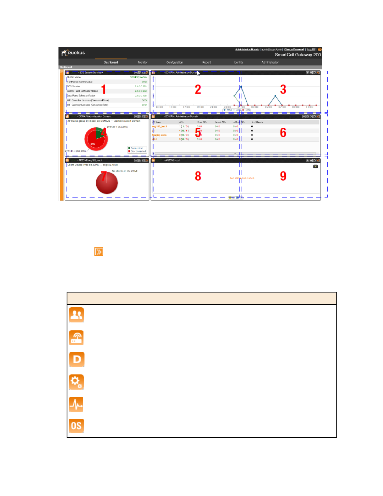
Widget Slots
The controller provides nine slots on the dashboard for placing widgets.
Figure 3: There are nine slots for widgets on the dashboard on page 25 marks these nine slots
on the dashboard.
Note that some widgets are wider (for example, the client count summary and data throughput
widgets) and require two widget slots. Make sure that there are enough empty slots on the
dashboard before you add or move a widget.
SmartCell Gateway 200/Virtual SmartZone High-Scale for Release 3.4.1 Administrator Guide
24
Page 25
Navigating the Web Interface
Using Widgets on the Dashboard
Figure 3: There are nine slots for widgets on the dashboard
Adding a Widget
Follow these steps to add a widget to the dashboard.
1.
Click the icon in the upper-left corner of the page (below the Ruckus Wireless icon).
The icons for adding widgets appear (see Table 3: Icons for adding widgets on page 25).
Table 3: Icons for adding widgets
Widget NameIcon
Client count summary widget
AP summary widget
Domain summary widget
System summary widget
Traffic summary widget
Client type summary widget
SmartCell Gateway 200/Virtual SmartZone High-Scale for Release 3.4.1 Administrator Guide
25
Page 26
Navigating the Web Interface
Using Widgets on the Dashboard
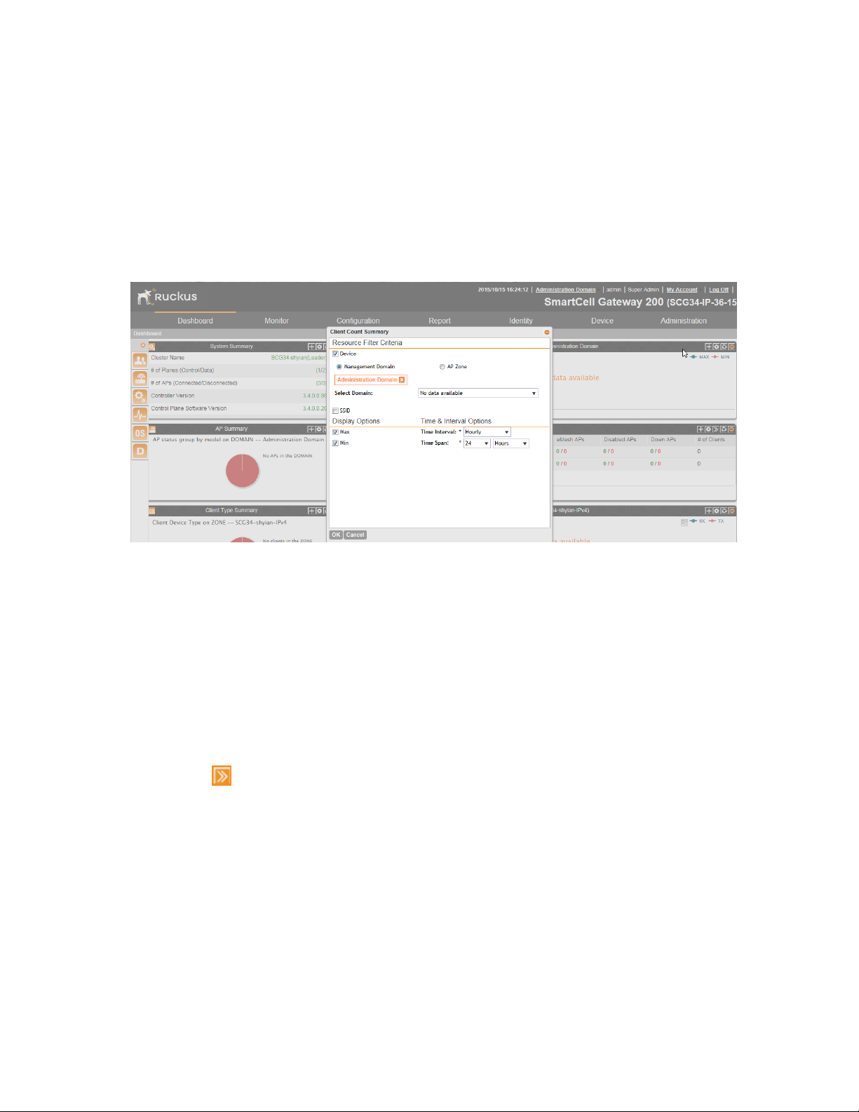
2. Click the icon for the widget that you want to add.
A configuration form, which contains widget settings that you can configure, appears.
3. Configure the widget settings.
4. Click OK.
The page refreshes, and then the widget that you added appears on the dashboard.
You have completed adding a widget. To add another widget, repeat the same procedure.
Figure 4: The configuration form for the Client Count Summary widget
Adding a Widget to a Widget Slot
A single widget slot can contain multiple widgets of the same size (one-slot widgets versus
two-slot widgets).
For example, you can add the client count summary widget and data throughput widget (both
are two-slot widgets) to the same widget slot.
Follow these steps to add a widget to a widget slot.
1. Locate an existing widget slot to which you want to add a widget.
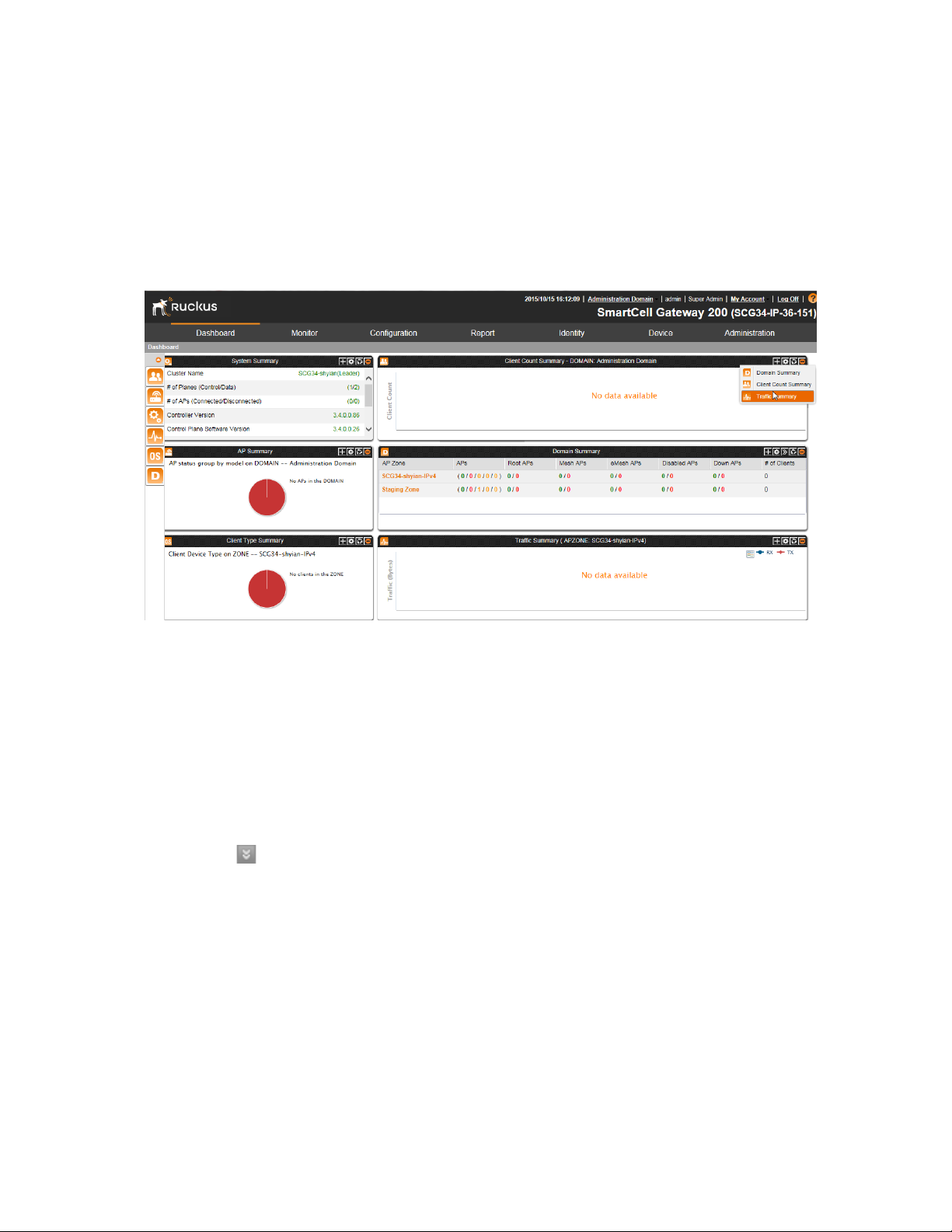
2.
Click the icon that is on the upper-right hand corner of the widget slot.
A submenu appears and displays the widgets that you can add to the widget slot.
3. Click the name of the widget that you want to add to the widget slot.
The widget configuration window appears.
NOTE: You can only add a widget once. If a widget already exists in a different widget slot,
you will be unable to add it to another widget slot.
4. Configure the information that you want the widget to display and the interval at which to
refresh the information on the widget.
SmartCell Gateway 200/Virtual SmartZone High-Scale for Release 3.4.1 Administrator Guide
26
Page 27
Navigating the Web Interface
Using Widgets on the Dashboard
NOTE: The refresh intervals for the client count summary and data throughput summary
widgets are non-configurable.
5. Click OK.
The widget slot refreshes, and then the widget that you added appears.
You have completed adding a widget to a widget slot.
Figure 5: Click the name of the widget that you want to add to the widget slot
Displaying a Widget in a Widget Slot
A widget slot that contains multiple widgets automatically cycles through the different widgets
that have been added to it at one-minute intervals.
If you want to view a specific widget in a widget slot, you can manually display it.
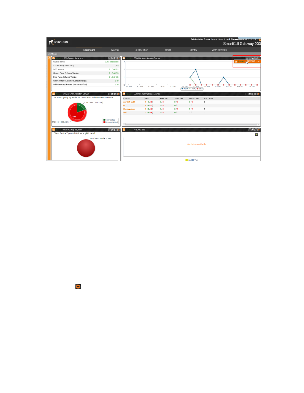
Follow these steps to display a widget that belongs to a widget slot manually.
1. Locate the widget slot that contains the widget that you want to display.
2.
Click the icon that is on the upper-right hand corner of the widget slot.
A submenu appears and displays the widgets that have been added to the widget slot.
3. Click the name of the widget that you want to display.
The widget slot refreshes, and the widget that you clicked appears.
You have completed displaying a widget in a widget slot.
SmartCell Gateway 200/Virtual SmartZone High-Scale for Release 3.4.1 Administrator Guide
27
Page 28
Navigating the Web Interface
Using Widgets on the Dashboard
Figure 6: Click the name of the widget that you want to display
Moving a Widget
Follow these steps to move a widget from one widget slot to another.
1. Make sure that there are sufficient slots for the widget that you want to move.
2. Hover your mouse pointer on the title bar of the widget.
The pointer changes into a four-way arrow.
3. Click-and-hold the widget, and then drag it to the empty slot to which you want to move it.
4. Release the widget.
You have completed moving a widget to another slot.
Deleting a Widget
Follow these steps to delete a widget.
1. Locate the widget that you want to delete.
2.
Click the icon that is on the upper-right hand corner of the widget.
A confirmation message appears.
3. Click OK to confirm.
The dashboard refreshes, and then the widget that you deleted disappears from the page.
4. Click OK to confirm that you want to delete this widget.
SmartCell Gateway 200/Virtual SmartZone High-Scale for Release 3.4.1 Administrator Guide
28
Page 29
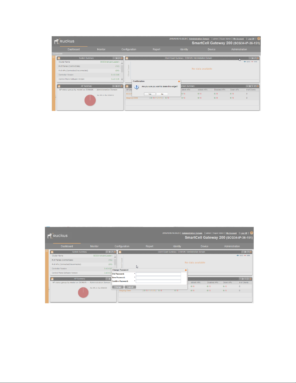
Figure 7: Click Yes to delete the widget
Changing the Administrator Password
Navigating the Web Interface
Changing the Administrator Password
Follow these steps to change the administrator password.
1. On the Miscellaneous Bar, click Change Password.
The Change Password form appears.
2. In Old Password, type your current password.
3. In New Password, type the new password that you want to use.
4. In Confirm Password, retype the new password above.
5. Click Change.
You have completed changing your administrator password. The next time you log on to the
controller, remember to use your new administrator password.
Figure 8: The Change Password form
SmartCell Gateway 200/Virtual SmartZone High-Scale for Release 3.4.1 Administrator Guide
29
Page 30
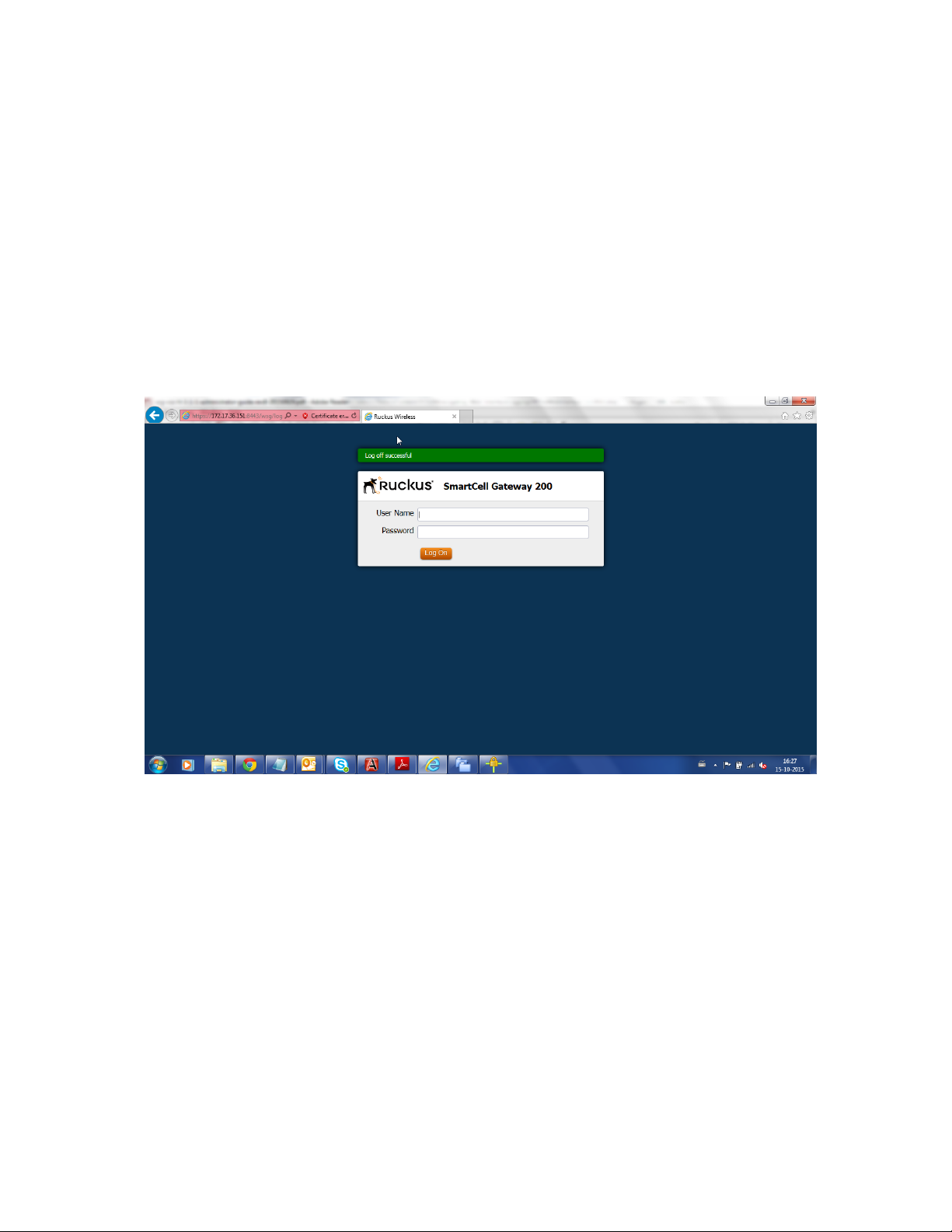
Logging Off the Web Interface
Follow these steps to log off the web interface.
1. On the Miscellaneous Bar, click Log Off.
A confirmation message appears.
2. Click Yes.
The controller logs you off the web interface. The logon page appears with the following
message above the Ruckus Wireless logo: Log off successful
You have completed logging off the web interface.
Navigating the Web Interface
Logging Off the Web Interface
Figure 9: The message Log off successful indicates that you have successfully logged
off the web interface
SmartCell Gateway 200/Virtual SmartZone High-Scale for Release 3.4.1 Administrator Guide
30
Page 31

31
Managing Ruckus Wireless AP Zones
In this chapter:
• Working with AP Zones
• Working with AP Groups
• Working with AAA Servers
• Working with Hotspot (WISPr) Portals
• Working with Guest Access Portals
• Working with Web Authentication Portals
• Working with Hotspot 2.0 Services
• Working with WLANs and WLAN Groups
• Working with WLAN Schedules
• Working with Device Policies
• Working with L2 Access Control Policies
• Working with Bonjour Policies
• Creating a DiffServ Profile
• Creating an Ethernet Port Profile
• Working With Dynamic PSKs
An AP zone functions as a way of grouping Ruckus Wireless APs and applying a particular set of
settings (including WLANs and their settings) to thise group of Ruckus Wireless APs. Each AP zone
can include up to 27 WLAN services.
2
Working with AP Zones
By default, an AP zone named Staging Zone exists. Any AP that registers with the controller that
is not assigned a specific zone is automatically assigned to the Staging Zone. This section
describes how to use AP zones to manage devices.
NOTE: When an AP is assigned or moved to the Staging Zone, the cluster name becomes its
user name and password after the AP shows up-to-date state. If you need to log on to the AP,
use the cluster name for the user name and password.
Before creating an AP zone, Ruckus Wireless recommends that you first set the default country
code on the Global Configuration page. This will help ensure that each new AP zone will use
the correct country code. For information on how to set the default country code, see Managing
Global Configuration on page 101.
Using the Domain Tree
Use the domain tree to find APs that you want to manage.
Clicking Configuration > AP Zones on the main menu displays a sidebar on the left side of the
page, which includes the domain tree.
SmartCell Gateway 200/Virtual SmartZone High-Scale for Release 3.4.1 Administrator Guide
31
Page 32

Managing Ruckus Wireless AP Zones
Working with AP Zones
The domain tree displays the management domains ( ) and AP zones ( ) that are under
Administration Domain. Clicking a domain icon in the tree displays the AP zones that belong
to it in the content area. Clicking an AP zone icon, on the other hand, displays detailed information
about the AP zone, including its general information, AAA server configuration, and hotspot
configuration.
NOTE: The search criteria are case-sensitive.
Figure 10: The domain tree
Creating an AP Zone
An AP zone functions as a way of grouping Ruckus Wireless APs and applying settings including
WLANs to these groups of Ruckus Wireless APs. Each AP zone can include up to six WLAN
services..
Follow these steps to create an AP zone.
NOTE: If you are planning to use SoftGRE tunneling for this AP zone, you must first create a
SoftGRE tunnel profile before creating the AP zone. For information on how to create a SoftGRE
tunnel profile, Creating a SoftGRE Tunnel Profile on page 103.
1. Click Configuration > AP Zones.
2. Click Create New.
The form for creating a new AP zone appears.
3. Configure General Options.
DescriptionOption
Type a name that you want to assign to this new zone.Zone Name
Type a description for this new zone. This is an optional field.Description
AP Firmware
Select the AP firmware version that you want the AP zone to use. By
default, the latest AP firmware available on the controller is selected.
SmartCell Gateway 200/Virtual SmartZone High-Scale for Release 3.4.1 Administrator Guide
32
Page 33

Managing Ruckus Wireless AP Zones
Working with AP Zones
DescriptionOption
Country Code
Location
Location
Additional
Information
GPS Coordinates
Time Zone
Select the country in which you are operating the access points. Different
countries and regions maintain different rules that govern which channels
can be used for wireless communications. Setting the country code to
the proper regulatory region helps ensure that the wireless network does
not violate local and national regulatory restrictions.
Type a location name (for example, Ruckus Wireless HQ) for this AP
zone.
Type additional information about the AP zone (for example, 350 W
Java Dr, Sunnyvale, CA 94089, United States).
Type the latitude, longitude and altitude coordinates for the AP zone's
location.
Specify the user name and password that administrators can use to log
on directly to the managed access point's native web interface. The
following boxes are provided:
• Logon ID: Type the admin user name.
• Password: Type the admin password.
Select the time zone that you want APs that belong to this zone to use.
Options include:
• System defined: Click this option, and then select a time zone from
the list.
• User defined: Click this option, and then configure a custom time
zone by setting the time zone abbreviation and GMT offset and
configuring daylight saving time support.
AP IP Mode
Select the IP addressing mode that you want APs (that belong to this
zone) to use. Options include:
• IPv4 Only: choosing this option allows you to perform IPv4 network
configuration on the AP zone
• IPv6 Only: choosing this option allows you to perform IPv6 network
configuration on the AP zone
• Dual: choosing this option allows you to perform both IPv4 and IPv6
network configuration on the AP zone
4. Configure Mesh Options.
DescriptionOption
Enable mesh
networking
Select this check box if you want managed APs to automatically form
a wireless mesh network, in which participant nodes (APs) cooperate
to route packets.
Dual band APs can only mesh with other dual band APs, while single
band APs can only mesh with other single band APs.
SmartCell Gateway 200/Virtual SmartZone High-Scale for Release 3.4.1 Administrator Guide
33
Page 34

Managing Ruckus Wireless AP Zones
Working with AP Zones
DescriptionOption
Mesh Name
(ESSID)
This option only appears when the Enable mesh networking check
box above is selected. Type a name for the mesh network. Alternatively,
do nothing to accept the default mesh name that the controller has
generated.
Mesh Passphrase
This option only appears when the Enable mesh networking check
box above is selected. Type a passphrase that contains at least 12
characters. This passphrase will be used by the controller to secure
the traffic between Mesh APs. Alternatively, click Generate to generate
a random passphrase with 32 characters or more.
5. Configure Radio Options.
DescriptionOption
Channel Range
(2.4G)
Select the check boxes for the channels on which you want the 2.4GHz
radios of managed APs to operate. Channel options include channels 1
to 11. By default, all channels are selected.
DFS Channels
If the country code that is selected in the General Options section of
this page is United States, the Allow DFS channels check boxs
appears. Selecting this check box adds Dynamic Frequency Selection
(DFS) channels to the list of 5GHz channels (see below) that managed
APs can use indoors and outdoors.
Channel Range
(5G) Indoor
Channel Range
(5G) Outdoor
b/g/n (2.4 GHz)
DFS channels, which are special channels allocated for radar signals,
can be used by unlicensed devices (such as APs and wireless clients) if
no radar signals are using them. If radar signals are detected on a DFS
channel that is currently used by devices, those devices will automatically
vacate the channel and use an alternate channel.
Select the check boxes for the channels on which you want the 5GHz
radios of managed indoor APs to operate. If you selected the Allow DFS
channels check box above, the list of channel options includes the DFS
channels.
Select the check boxes for the channels on which you want the 5GHz
radios of managed outdoor APs to operate. If you selected the Allow
DFS channels check box above, the list of channel options includes the
DFS channels.
Configure the following options:Radio Options
• Channelization: Set the channel width used during transmission to
either 20 or 40 (MHz), or select Auto to set it automatically.
• Channel: Select the channel to use for the b/g/n (2.4GHz) radio, or
select Auto to set it automatically.
• TX Power Adjustment: Select the preferred TX power, if you want
to manually configure the transmit power on the 2.4GHz radio. By
default, TX power is set to Full on the 2.4GHz radio
SmartCell Gateway 200/Virtual SmartZone High-Scale for Release 3.4.1 Administrator Guide
34
Page 35

Managing Ruckus Wireless AP Zones
Working with AP Zones
DescriptionOption
Configure the following options:Radio Options
a/n/c (5GHz)
• Channelization: Set the channel width used during transmission to
either 20, 40, or 80 (MHz), or select Auto to set it automatically.
• Channel (Indoor): Select the indoor channel to use for the a/n/c
(5GHz) radio, or select Auto to set it automatically.
• Channel (Outdoor): Select the outdoor channel to use for the a/n/c
(5GHz) radio, or select Auto to set it automatically.
• TX Power Adjustment: Select the preferred TX power, if you want
to manually configure the transmit power on the 5GHz radio. By
default, TX power is set to Full on the 5GHz radio.
6. Configure AP GRE Tunnel Options.
• Tunnel Type: Select a protocol to use for tunneling WLAN traffic back to the controller.
Options include RuckusGRE, SoftGRE, and SoftGRE+IPSec.
NOTE: AP zones configured with IPv6 network address configuration only support
RuckusGRE tunnel type.
• Tunnel Profile: Select the tunnel profile that you want to use. If you want to use Ruckus
GRE tunneling for this AP zone, you can use the default tunnel profile or you can select a
profile that you created. If you want to use SoftGRE tunneling, you must first create a
SoftGRE tunnel profile.
SoftGRE tunnel type support IPv4 SoftGER and IPv6 SoftGRE tunnel profiles, and
SoftGRE+IPSec tunnel type support IPv4 SoftGRE and IPv6 IPSec tunnel profiles.
NOTE: For more information on creating Ruckus GRE and SoftGRE tunnel profiles, see
Creating AP Tunnel Profiles.
Table 4: Tunnel Types
Encrypted with IPsecUnencryptedTunnel Type
SupportedSupportedRuckus GRE over IPv4
Supported*Supported*Ruckus GRE over IPv6
SupportedSupportedSoftGRE over IPv4
Supported*Supported**SoftGRE over IPv6
NOTE: * indicates that tunneling over IPv6 is supported only in AP zones supporting IPv6.
Dual-stack zones will not tunnel with IPv6.
NOTE: ** indicates that SoftGRE tunneling over IPv6 is supported in AP zones with IPv6 and
dual-stack AP zones.
SmartCell Gateway 200/Virtual SmartZone High-Scale for Release 3.4.1 Administrator Guide
35
Page 36

Managing Ruckus Wireless AP Zones
Working with AP Zones
7. Configure Syslog Options.
• To send events related to APs in this zone to an external syslog server, select the Enable
external syslog server for APs in this zone check box. Additional options appear below.
• Server Address: Type the IP address of the syslog server on the network.
NOTE: The IP address format that you enter here will depend on the AP IP mode that you
selected earlier in this procedure. If you selected IPv4 Only, enter an IPv4 address. If you
selected IPv6 Only, enter an IPv6 address.
• Port: Type the syslog port number on the server.
• Facility: Select the facility level that will be used by the syslog message. Options include
Local0 (default), Local1, Local2, Local3, Local4, Local5, Local6, and Local7.
• Priority: Select the lowest priority level for which events will be sent to the syslog server.
For example, to only receive syslog messages for events with the warning (and higher)
priority, select Warning. To receive syslog messages for all events, select All.
8. Configure the AP SNMP Options: select the Enable AP SNMP check-box to configure the
SNMPv2 and SNMPv3 settings.
9. Configure Advanced Options.
DescriptionOption
Channel Mode
Auto Channel Selection
Background Scanning
If you want to allow outdoor APs that belong
to this zone to use wireless channels that are
regulated as indoor-use only, select the Allow
indoor channels check box. For more
information, see Channel Mode on page 76.
You can adjust the AP channel to 2.4 GHz or
5 GHz frequencies by selecting the
appropriate check-box.
Further, you can automatically adjust the AP
to optimize performance by choosing one of
the following:
• Background Scanning : Changes the AP
channel if there is interference.
• ChannelFly: Continuously monitors
potential throughput and changes the AP
channel to minimize interference and
optimize throughput.
If you want APs to evaluate radio channel
usage automatically, enable and configure the
background scanning settings on both the
2.4GHz and 5GHz radios. By default,
background scanning is enabled on both
radios and is configured to run every 20
seconds.
SmartCell Gateway 200/Virtual SmartZone High-Scale for Release 3.4.1 Administrator Guide
36
Page 37

Managing Ruckus Wireless AP Zones
Working with AP Zones
DescriptionOption
Smart Monitor
To disable the WLANs of an AP (that belongs
to this zone) whenever the AP uplink or
Internet connection becomes unavailable,
select the Enable check box. And then,
configure the following options:
• Health Check Interval: Set the interval
(between 5 and 60 seconds) at which the
AP will check its uplink connection. The
default value is 10 seconds.
• Health Check Retry Threshold: Set the
number of times (between 1 and 10 times)
that the AP will check its uplink connection.
If the AP is unable to detect the uplink after
the configured number of retries, the AP
will disable its WLANs. The default value
is 3 retries.
NOTE: When the AP disables its WLANs,
the AP creates a log for the event. When
the AP's uplink is restored, it sends the
event log (which contains the timestamp
when the WLANs were disabled, and then
enabled) to the controller.
VLAN Pooling
AP Management VLAN
Rogue AP Detection
This option allows you to overlap VLANs
within VLAN pooling profiles. For example, if
a VLAN profile by name vlan-pooling-1 uses
VLAN IDs 100 to 105, and another profile
vlan-pooling-2 uses VLAN IDs 102 to 107,
the overlapping VLAN IDs are 102 to 105.
For more information, see About VLAN
Pooling.
To override the management VLAN tag that
has been configured on the AP, click VLAN
ID, and then type the VLAN ID that you want
to assign (valid range is from 1 to 4094). To
keep the same management VLAN ID that
has been configured on the AP, click Keep
AP's settings.
Select the Report rogue access points
check box to enable rogue device detection
in logs and email alarm event notifications.
• Report all rogue devices: Send alerts for
all rogue AP events.
SmartCell Gateway 200/Virtual SmartZone High-Scale for Release 3.4.1 Administrator Guide
37
Page 38

Managing Ruckus Wireless AP Zones
Working with AP Zones
DescriptionOption
• Report only malicious rogue devices of
type: Select which event types to report.
Events include SSID spoofing, same
network, and MAC spoofing.
• Protect the network from malicious
rogue access points: Select this check
box to automatically protect your network
from network connected rogue APs,
SSID-spoofing APs and MAC-spoofing
APs. When one of these rogue APs is
detected (and this check box is enabled),
the Ruckus Wireless AP automatically
begins sending broadcast
de-authentication messages spoofing the
rogue's BSSID (MAC) to prevent wireless
clients from connecting to the malicious
rogue AP. This option is disabled by
default.
Client Load Balancing
Band Balancing
Improve WLAN performance by enabling load
balancing. Load balancing spreads the
wireless client load between nearby access
points, so that one AP does not get
overloaded while another sites idle. Load
balancing must be enabled on a per-radio
basis. To enable load balancing, select the
Enable loading balancing on [2.4GHz or
5GHz] check box, and then set or accept the
default Adjacent Radio Threshold (50dB for
the 2.4GHz radio and 43dB for the 5GHz
radio).
Client band balancing between the 2.4GHz
and 5GHz radio bands is disabled by default
on all WLANs. To enable band balancing for
this WLAN, select the Enable band balancing
on radios by distributing the clients on 2.4GHz
and 5GHz bands check box, and then set the
percentages of client load that will be
distributed between the 2.4GHz and 5Ghz
bands. For more information, see Band
Balancing on page 77.
Location Based Service
To enable LBS service for this AP zone, select
the Enable LBS Service check box, and then
select an LBS server to use from the
drop-down list. For information on how to add
SmartCell Gateway 200/Virtual SmartZone High-Scale for Release 3.4.1 Administrator Guide
38
Page 39

Managing Ruckus Wireless AP Zones
Working with AP Zones
DescriptionOption
an LBS server to the controller, see
Configuring Location Services on page 167.
Client Admission Control
Set the load thresholds on the AP at which it
will stop accepting new clients. See
Configuring Client Admission Control.
AP Reboot Timeout
Set the time after which the AP will reboot
automatically when it is unable to reach the
default gateway or the control interface.
• Reboot AP if it cannot reach default
gateway after [ ] minutes: The default
timeout is 30 minutes.
• Reboot AP if it cannot reach the
controller after [ ]: The default timeout is
2 hours.
10. Click OK to finish creating your first AP zone.
When the controller completes creating the AP zone, the following confirmation message
appears: AP zone created successfully. Do you want to view the
configuration details?
11. Click Yes to view the AP zone details, or click No to close the confirmation message and
return to the AP zone list.
You have completed creating an AP zone. You can create additional AP zones as needed.
SmartCell Gateway 200/Virtual SmartZone High-Scale for Release 3.4.1 Administrator Guide
39
Page 40

Managing Ruckus Wireless AP Zones
Working with AP Zones
Figure 11: The Create New AP Zone form
ChannelFly and Background Scanning
SmartZone controllers offer the ChannelFly and Background Scanning automatic channel selection
methods for spectrum utilization and performance optimization. While Background Scanning
must be enabled for rogue AP detection, AP location detection and radio power adjustment,
either can be used for automatic channel optimization.
The main difference between ChannelFly and Background Scanning is that ChannelFly determines
the optimal channel based on real-time statistical analysis of actual throughput measurements,
while Background Scanning uses channel measurement and other techniques to estimate the
impact of interference on Wi-Fi capacity based on progressive scans of all available channels.
NOTE: If you enable ChannelFly, Background Scanning can still be used for adjusting radio
power and rogue detection while ChannelFly manages the channel assignment. Both cannot
be used at the same time for channel management.
Benefits of ChannelFly
With ChannelFly, the AP intelligently samples different channels while using them for service.
ChannelFly assesses channel capacity every 15 seconds and changes channel when, based
on historical data, a different channel is likely to offer higher capacity than the current channel.
Each AP makes channel decisions based on this historical data and maintains an internal log of
channel performance individually.
When ChannelFly changes channels, it utilizes 802.11h channel change announcements to
seamlessly change channels with no packet loss and minimal impact to performance. The
802.11h channel change announcements affect both wireless clients and Ruckus mesh nodes
in the 2.4 GHz and/or 5 GHz bands.
SmartCell Gateway 200/Virtual SmartZone High-Scale for Release 3.4.1 Administrator Guide
40
Page 41

Managing Ruckus Wireless AP Zones
Working with AP Zones
Initially (in the first 30-60 minutes) there will be more frequent channel changes as ChannelFly
learns the environment. However, once an AP has learned about the environment and which
channels are most likely to offer the best throughput potential, channel changes will occur less
frequently unless a large measured drop in throughput occurs.
ChannelFly can react to large measured drops in throughput capacity in as little as 15 seconds,
while smaller drops in capacity may take longer to react to.
Disadvantages of ChannelFly
Compared to Background Scanning, ChannelFly takes considerably longer for the network to
settle down. If you will be adding and removing APs to your network frequently, Background
Scanning may be preferable. Additionally, if you have clients that do not support the 802.11h
standard, ChannelFly may cause significant connectivity issues during the initial capacity
assessment stage.
You can enable/disable ChannelFly per band. If you have 2.4 GHz clients that do not support
802.11h, Ruckus recommends disabling ChannelFly for 2.4 GHz but leaving it enabled for the
5 GHz band.
Background Scanning
Using Background Scanning, SmartZone controllers regularly samples the activity in all Access
Points to assess RF usage, to detect rogue APs and to determine which APs are near each
other for mesh optimization. These scans sample one channel at a time in each AP so as not
to interfere with network use. This information is then applied in AP Monitoring and other controller
monitoring features. You can, if you prefer, customize the automatic scanning of RF activity,
deactivate it if you feel it's not helpful, or adjust the frequency, if you want scans at greater or
fewer intervals.
NOTE: Background Scanning must be enabled for SmartZone controllers to detect rogue APs
on the network.
VLAN Pooling
When Wi-Fi is deployed in a high density environment (such as a stadium) or on a university
campus to provide access for students, the number of IP addresses required for client devices
can easily run into several thousands.
Allocating a single large subnet results in a high probability of degraded performance due to
factors like broadcast/multicast traffic.
To address this problem, VLAN pooling provides a method by which administrators can deploy
pools of multiple VLANs from which clients are assigned, thereby automatically segmenting large
groups of clients into smaller subgroups, even when connected to the same SSID.
As the client device joins the Wi-Fi network, the VLAN is assigned based on a hash of the client’s
MAC address (by default).
SmartCell Gateway 200/Virtual SmartZone High-Scale for Release 3.4.1 Administrator Guide
41
Page 42

Managing Ruckus Wireless AP Zones
Working with AP Zones
Cloning an AP Zone from the Domain Tree
Cloning an AP zone enables you to copy the configuration of an existing zone and save it as a
new zone.
If you need to create an AP zone with configuration settings that are similar to an existing AP
zone, cloning that existing AP zone would be the easiest way to do it.
Follow these steps to clone an AP zone.
1. Go to Configuration > AP Zones.
2. In the domain tree, find the AP zone that you want to clone.
3. Click Clone.
A form appears and prompts you for the name that you want to assign to the cloned zone.
The default name is Clone of {Original Zone Name}.
4. Edit the AP zone name or leave it as is.
5. Click OK to finish cloning the AP zone.
Figure 12: Click the Clone button to save the AP zone as a new zone
Cloning an AP Zone from the AP Zone List
Another method to save an existing AP zone as a new zone is by cloning it from the AP Zone
List page.
Follow these steps to clone an AP zone from the AP Zone List page.
1. Go to Configuration > AP Zones.
2. On the AP Zones List page, find the AP zone that you want to clone.
3. Click the action icon that is in the same row as the AP zone name.
4. A form appears and prompts you for the name that you want to assign to the cloned zone.
The default name is Clone_of_{Original Zone Name}.
5. Edit the AP zone name or leave it as is.
6. Click Apply.
SmartCell Gateway 200/Virtual SmartZone High-Scale for Release 3.4.1 Administrator Guide
42
Page 43

Managing Ruckus Wireless AP Zones
Working with AP Zones
The page refreshes, and then the AP zone that you cloned appears in the AP Zone List.
You have completed cloning an AP zone from the AP zone list. need graphic A form prompts
you for the name that you want to assign to the cloned zone
Viewing Existing AP Zones
Follow these steps to view a list of existing AP zones.
1. Go to Configuration > AP Zones.
The AP Zone List page appears and displays a list of existing AP zones.
2. To view the configuration of a specific zone, locate the zone whose details you want to view
on the AP Zone List page.
3. Under the Zone Name column, click the AP zone name.
The page refreshes and displays the AP zone configuration page.
Figure 13: The AP Zone List page
Viewing the AP Zone Configuration
Follow these steps to view a summary of the AP zone configuration.
1. Go to Configuration > AP Zones.
2. On the AP Zone List page, click the name of the AP zone that you want to view.
The Zone Configuration page for the AP zone appears and displays as summary of the AP
zone configuration.
SmartCell Gateway 200/Virtual SmartZone High-Scale for Release 3.4.1 Administrator Guide
43
Page 44

Managing Ruckus Wireless AP Zones
Working with AP Zones
Figure 14: The Zone Configuration page displays a summary of the zone settings
The following buttons and options also appear on the page:
• Edit: Click to edit the AP zone configuration.
• Clone: Click to clone this AP zone.
• Move: Click to move this AP zone from its current management domain to another.
• Delete: Click to delete this AP zone.
If you want to override the AP zone settings for specific AP models, configure the AP
Model-Specific Configuration section at the bottom of the page (see Modifying Model Specific
Controls for more information).
Deleting an AP Zone
Deleting an AP zone that contains managed devices will automatically move those devices to
the Staging Zone (default zone).
Before deleting an AP zone, Ruckus Wireless recommends moving devices that belong to that
zone to another zone.
Follow these steps to delete an AP zone.
1. Go to Configuration > AP Zones.
2. In the domain tree, select the AP zone that you want to delete.
3. Click the Delete Selected button.
A confirmation message appears.
4. Click OK.
You have completed deleting an AP zone.
SmartCell Gateway 200/Virtual SmartZone High-Scale for Release 3.4.1 Administrator Guide
44
Page 45

Managing Ruckus Wireless AP Zones
Working with AP Groups
Working with AP Groups
AP (access point) groups can be used to define configuration options and apply them to groups
of APs at once, without having to individually modify each AP’s settings.
For each group, administrators can create a configuration profile that defines the channels, radio
settings, Ethernet ports and other configurable fields for all members of the group or for all APs
of a specific model in the group. AP groups are similar to WLAN groups (see Working with WLAN
Groups for more information). While WLAN groups can be used to specify which WLAN services
are served by which APs, AP groups are used for more specific fine-tuning of how the APs
themselves behave.
NOTE: AP group configuration settings can be overridden by individual AP settings. For example,
if you want to set the transmit power to a lower setting for only a few specific APs, leave the Tx
Power Adjustment at Auto in the AP group configuration page, then go to the individual AP
configuration page (Configuration > Access Points > Edit [AP MAC address]) and set the Tx
Power Setting to a lower setting.
Creating an AP Group
Creating an AP group means creating a configuration profile that defines the channels, radio
settings, Ethernet ports and other configurable fields for all members of the group or for all APs
of a specific model in the group.
Follow these steps to create an AP group.
1. Go to Configuration > AP Zones.
2. On the AP Zone List page, click the AP zone name within which you want to create the AP
group.
The page refreshes, and the AP Zone submenu appears on the sidebar.
3. On the sidebar, click AP Groups.
4. Click Create New.
The Create New AP Groups form appears.
5. In General Settings, configure the following:
• Name: Type a name for this AP group.
• Description: Type a description for this AP group.
• Location: Type a location name (for example, Ruckus Wireless HQ) for this AP group.
• Location Additional Information: Type additional location information for the AP group,
if any (for example, 350 W Java Dr, Sunnyvale, CA 94089, United States).
You can select the Override zone configuration check-box if you want to cancel the AP
zone configuration that was set previously.
• GPS Coordinates: Type the longitude, altitude, and latitude coordinates for the AP group's
location.
6. In Group Members, configure the following:
SmartCell Gateway 200/Virtual SmartZone High-Scale for Release 3.4.1 Administrator Guide
45
Page 46

Managing Ruckus Wireless AP Zones
Working with AP Groups
• Members: When you are creating a new AP group, this section will be empty. This will be
populated after you select the access points that you want to belong to this AP group.
• Access Points: This section shows all the access points that currently belong to the AP
zone. Select the check boxes before the Member column (which shows the AP MAC
addresses) of each AP that you want to add to the AP group, and then click Add to Group.
The APs you selected appear under the Members section.
7. In Radio Options, if you want to override a setting that has been defined for this zone, select
the Override zone configuration check box for that setting, and then configure that setting
(see the table below for more information about each setting). If you want to preserve the
original configuration of the zone, skip this step.
DescriptionOption
Channel Range
(2.4G)
DFS Channels
Channel Range
(5G) Indoor
Channel Range
(5G) Outdoor
If you want to override the 2.4GHz channel range that has been configured
for the zone to which this AP group belong, select Select the check boxes
for the channels on which you want the 2.4GHz radios of managed APs
to operate. Channel options include channels 1 to 11. By default, all
channels are selected.
If the country code that is selected in the General Options section of this
page is United States, the Allow DFS channels check boxs appears.
Selecting this check box adds Dynamic Frequency Selection (DFS)
channels to the list of 5GHz channels (see below) that managed APs can
use indoors and outdoors.
DFS channels, which are special channels allocated for radar signals, can
be used by unlicensed devices (such as APs and wireless clients) if no
radar signals are using them. If radar signals are detected on a DFS
channel that is currently used by devices, those devices will automatically
vacate the channel and use an alternate channel.
Select the check boxes for the channels on which you want the 5GHz
radios of managed indoor APs to operate. If you selected the Allow DFS
channels check box above, the list of channel options includes the DFS
channels.
Select the check boxes for the channels on which you want the 5GHz
radios of managed outdoor APs to operate. If you selected the Allow
DFS channels check box above, the list of channel options includes the
DFS channels.
Configure the following options:Radio Options
b/g/n (2.4 GHz)
• Channelization: Set the channel width used during transmission to
either 20 or 40 (MHz), or select Auto to set it automatically.
• Channel: Select the channel to use for the b/g/n (2.4GHz) radio, or
select Auto to set it automatically.
• TX Power Adjustment: Select the preferred TX power, if you want to
manually configure the transmit power on the 2.4GHz radio. By default,
TX power is set to Full on the 2.4GHz radio
• WLAN Group: Specify to which WLAN group this AP group belongs.
SmartCell Gateway 200/Virtual SmartZone High-Scale for Release 3.4.1 Administrator Guide
46
Page 47

Managing Ruckus Wireless AP Zones
Working with AP Groups
DescriptionOption
Configure the following options:Radio Options
a/n/c (5GHz)
• Channelization: Set the channel width used during transmission to
either 20, 40, or 80 (MHz), or select Auto to set it automatically.
• Channel (Indoor): Select the indoor channel to use for the a/n/c
(5GHz) radio, or select Auto to set it automatically.
• Channel (Outdoor): Select the outdoor channel to use for the a/n/c
(5GHz) radio, or select Auto to set it automatically.
• TX Power Adjustment: Select the preferred TX power, if you want to
manually configure the transmit power on the 5GHz radio. By default,
TX power is set to Full on the 5GHz radio.
• WLAN Group: Specify to which WLAN group this AP group belongs.
8. In AP SNMP Options, select the Override zone configuration check-box to replace the
AP zone configuration, and select the Enable AP SNMP check-box to configure the SNMP
settings.
9. In Model Specific Options, configure LED, LLDP, and port settings of all APs of each specific
model that are members of the AP group.
See Modifying Model Specific Controls.
10. In Advanced Options, select the Override zone config check boxes for the settings that
you want to override, and then configure them.
• Location Based Service: To disable the LBS service for this AP group, clear the Enable
LBS service check box. To use a different LBS server for this AP group, select the Enable
LBS service check box, and then select the LBS server that you want to use from the
drop-down list.
• Hotspot 2.0 Venue Profile: If you have configured Hotspot 2.0 venue profiles, select the
profile that you want to assign to this AP group.
• AP Management VLAN: To override the management VLAN tag that has been configured
on the AP, click VLAN ID, and then type the VLAN ID that you want to assign (valid range
is from 1 to 4094). To keep the same management VLAN ID that has been configured on
the AP, click Keep AP's settings
• Client Admission Control: Set the load thresholds on the AP at which it will stop accepting
new clients. See Configuring Client Admission Control.
11. Click OK.
You have completed creating an AP group.
SmartCell Gateway 200/Virtual SmartZone High-Scale for Release 3.4.1 Administrator Guide
47
Page 48

Figure 15: The Create New AP Group form
Managing Ruckus Wireless AP Zones
Working with AP Groups
Configuring Model Based Settings If you want to apply a set of settings to all APs of a particular model, use the Model Based Settings page.
Follow the steps to configure the model based settings.
1. On the menu, click Configuration > Access Points.
The AP List page appears.
2. Click the MAC address of the AP for which you want to configure the model based settings.
The Edit AP Configuration form appears.
3. Scroll down to Model Specific Options section, and then click the + icon to expand the
section.
4. In Model Specific Control, select the Override zone configuration check box.
The settings available for the AP model appear.
5.
NOTE: The options that appear in the General Options section depend on the AP model
that you select. Not all the options described in the table below will appear for every AP model.
In the General Options section, configure the following settings:
DescriptionOption
PoE out port
To enable the PoE out port on the selected AP model, select the Enable
PoE out ports (specific ZoneFlex AP models only) .
NOTE: If the controller country code is set to United Kingdom, an
additional Enable 5.8 GHz Channels option will be available for outdoor
11n/11ac APs. Enabling this option allows the use of restricted C-band
channels. These channels are disabled by default and should only be
enabled by customers with a valid license to operate on these restricted
channels.
SmartCell Gateway 200/Virtual SmartZone High-Scale for Release 3.4.1 Administrator Guide
48
Page 49

Managing Ruckus Wireless AP Zones
Working with AP Groups
DescriptionOption
PoE Operating
Mode
Internal Heater
Status LEDs
LLDP
External Antenna
(2.4 GHz)
External Antenna
(5 GHz)
USB Port
Select the PoE operating mode of the selected AP model. Available
options include Auto (default), 802.3af and 802.3at mode. If 802.3af
PoE is selected, this AP model will operate in 802.3af mode and will
consume less power than in 802.3at mode. However, when this option
is selected, some AP features are disabled to reduce power
consumption, such as the USB port and one of the Ethernet ports. See
the Access Point User Guide for model-specific information.
To enable the heater that is built into the selected AP model, select the
Enable internal heaters (specific AP models only) check box.
To disable the status LED on the selected AP model, select the Disable
Status LEDs check box.
To enable the Link Layer Discovery Protocol (LLDP) on the selected AP
model, select the Enable Link Layer Discovery Protocol check box.
To enable the external 2.4 GHz antenna on the selected AP model,
select the Enable external antenna check box, and then set the gain
value (between 0 and 90dBi) in the box provided.
To enable the external 5 GHz antenna on the selected AP model, select
the Enable external antenna check box, and then set the gain value
(between 0 and 90dBi) in the box provided.
To disable the USB port on the selected AP model, select the Disable
USB port check box. USB ports are enabled by default.
6.
NOTE: The number of LAN ports that appear in this section correspond to the physical LAN
ports that exist on the selected AP model.
NOTE: When trunk port limitation is enabled, the controller does not validate the port settings
configured in the AP or the AP group with no members.
In the Port Settings section, configure the following options for each LAN port.
DescriptionOption
Enable check
box
Use this option to enable and disable this LAN port on the selected AP
model. By default, this check box is selected. To disable this LAN port,
clear this check box.
Profile
Use this option to select the Ethernet port profile that you want this LAN
port to use. Two default Ethernet port profile exist: Default Trunk Port
(selected by default) and Default Access Port. If you created Ethernet port
profiles (see Creating an Ethernet Port Profile on page 93), these profiles
will also appear on the drop-down list.
NOTE: If you recently created an Ethernet port profile and it does not appear
on the drop-down menu, click Reload on the drop-down menu to refresh
the Ethernet port profile list.
SmartCell Gateway 200/Virtual SmartZone High-Scale for Release 3.4.1 Administrator Guide
49
Page 50

Managing Ruckus Wireless AP Zones
Working with AP Groups
7. Click Apply.
The message Please wait... appears. When the message disappears, you have
completed configuring the settings of the selected AP model.
Figure 16: Options for configuring AP model specific settings
Supported LLDP Attributes
The Link Layer Discovery Protocol (LLDP) is a vendor-neutral Layer 2 protocol that allows a
network device (for example, a Ruckus Wireless AP) to advertise its identity and capabilities on
the local network.
LLDP information is sent by devices from each of their interfaces at a fixed interval (default is 30
seconds), in the form of an Ethernet frame. Each LLDP Ethernet frame contains a sequence of
type-length-value (TLV) structures starting with Chassis ID, Port ID and Time to Live (TTL) TLV.
Table 2 lists the LLDP attributes supported by the controller.
Table 5: LLDP attributes supported by the controller
DescriptionAttribute (TLV)
Indicates the MAC address of the AP’s br0 interfaceChassis ID
Identifies the port from which the LLDP packet was sentPort ID
Time to Live
Same as LLDP Hold Time. Indicates the length of time (in
seconds) that a receiving device will hold the LLDP information
SmartCell Gateway 200/Virtual SmartZone High-Scale for Release 3.4.1 Administrator Guide
50
Page 51

Managing Ruckus Wireless AP Zones
Working with AP Groups
DescriptionAttribute (TLV)
sent by the selected AP model before discarding it. The default
value is 120 seconds.
System Name
Indicates the name assigned to the AP. The default name of
Ruckus Wireless APs is RuckusAP.
Indicates the AP model plus software versionSystem Description
System Capabilities
Indicates the AP’s capabilities (Bridge, WLAN AP, Router,
Docsis), and which capabilities are enabled
Indicates the management IP address of the APManagement Address
Indicates the description of the port in alphanumeric formatPort Description
Configuring the Port Settings of a Particular AP Model
Use Port Settings in the AP Model-Specific Configuration section to configure the Ethernet
ports of a particular AP model.
Follow these steps to configure the port settings of a certain AP model.
1. All ports are enabled by default (the Enable check boxes are all selected). To disable a particular
port entirely, clear the Enable check box next to the port name (LAN1, LAN2, etc.)
2. For any enabled ports, you can choose whether the port will be used as a Trunk Port, Access
Port, or General Port.
The following restrictions apply:
• All APs must be configured with at least one Trunk Port.
NOTE: You cannot move an AP model to an AP group and configure the AP model to
use a trunk port at the same time, if general ports are enabled when trunk port limitation
is disabled. You must configure the selected AP model to use at least one trunk port, and
then move the AP model to the AP group.
• For single port APs, the single LAN port must be a trunk port and is therefore not
configurable.
• For ZoneFlex 7025/7055, the LAN5/Uplink port on the rear of the AP is defined as a Trunk
Port and is not configurable. The four front-facing LAN ports are configurable.
• For all other APs, you can configure each port individually as either a Trunk Port, Access
Port, or General Port. See Designating an Ethernet Port Type on page 52 for more
information.
Figure 17: The Port Settings section
SmartCell Gateway 200/Virtual SmartZone High-Scale for Release 3.4.1 Administrator Guide
51
Page 52

Managing Ruckus Wireless AP Zones
Working with AP Groups
Designating an Ethernet Port Type
Ethernet ports can be configured as access ports, trunk ports, or general ports.
Trunk links are required to pass VLAN information between switches. Access ports provide
access to the network and can be configured as members of specific VLANs, thereby separating
the traffic on these ports from traffic on other VLANs. General ports are user-defined ports that
can have any combination of up to 20 VLAN IDs assigned.
For most ZoneFlex APs, you can set which ports you want to be your Access, Trunk and General
Ports from the controller web interface, as long as at least one port on each AP is designated
as a Trunk Port.
By default, all ports are enabled as Trunk Ports with Untag VLAN set as 1 (except for ZoneFlex
7025, whose front ports are enabled as Access Ports by default). If configured as an Access
Port, all untagged ingress traffic is the configured Untag VLAN, and all egress traffic is untagged.
If configured as a Trunk Port, all untagged ingress traffic is the configured Untag VLAN (by default,
1), and all VLAN-tagged traffic on VLANs 1-4094 will be seen when present on the network.
The default Untag VLAN for each port is VLAN 1. Change the Untag VLAN to:
• Segment all ingress traffic on this Access Port to a specific VLAN.
• Redefine the native VLAN on this Trunk Port to match your network configuration.
When trunk port limitation is disabled using the eth-port-validate-one-trunk disable
command, validation checks are not performed for the VLAN members and the AP Management
VLAN. If the AP configuration for general ports and access ports does not include a member of
an AP management VLAN, or the VLAN of a WAN interface configured through CLI, the AP will
disconnect and the Ethernet port stops transmitting data. Make sure that you configure the
correct VLAN member in the ports (general/access) and the AP management VLAN.
NOTE: Ensure that at least one of the general port VLANs is the same as a Management VLAN
of the AP.
Access Ports
Access ports provide access to the network and can be configured as members of a specific
VLAN, thereby separating the traffic on these ports from traffic on other VLANs.
All Access Ports are set to Untag (native) VLAN 1 by default. This means that all Access Ports
belong to the native VLAN and are all part of a single broadcast domain. When untagged frames
from a client arrive at an AP’s Access Port, they are given an 802.1Q VLAN header with 1 as
their VLAN ID before being passed onto the wired network.
When VLAN 1 traffic arrives destined for the client, the VLAN tag is removed and it is sent as
plain (untagged) 802.11 traffic. When any tagged traffic other than VLAN 1 traffic arrives at the
same Access Port, it is dropped rather than forwarded to the client.
To remove ports from the native VLAN and assign them to specific VLANs, select Access Port
and enter any valid VLAN ID in the VLAN ID field (valid VLAN IDs are 2-4094).
The following table describes the behavior of incoming and outgoing traffic for Access Ports with
VLANs configured.
SmartCell Gateway 200/Virtual SmartZone High-Scale for Release 3.4.1 Administrator Guide
52
Page 53

Table 6: Access Ports with VLANs configured
Managing Ruckus Wireless AP Zones
Working with AP Groups
Outgoing Traffic (to Client)Incoming Traffic (from Client)VLAN Settings
Access Port, Untag VLAN
1
Access Port, Untag
VLAN [2-4094]
All incoming traffic is native VLAN
(VLAN 1).
All incoming traffic is sent to the
VLANs specified.
All outgoing traffic on the port
is sent untagged.
Only traffic belonging to the
specified VLAN is forwarded. All
other VLAN traffic is dropped.
Trunk Ports
Trunk links are required to pass VLAN information between switches. Trunking is a function that
must be enabled on both sides of a link.
If two switches are connected together, for example, both switch ports must be configured as
trunk ports.
The trunk port is a member of all the VLANs that exist on the AP/switch and carries traffic for all
VLANs between switches.
For a trunk port, the VLAN Untag ID field is used to define the native VLAN - the VLAN into which
untagged ingress packets are placed upon arrival. If your network uses a different VLAN as the
native VLAN, configure the AP trunk port’s VLAN Untag ID with the native VLAN used throughout
your network.
General Ports
General ports are user-specified ports that can have any combination of up to 20 VLAN IDs
assigned.
General ports function similarly to Trunk ports, except that where Trunk ports pass all VLAN
traffic, General ports pass only the VLAN traffic that is defined by the user.
To configure an AP Ethernet port as a General port, select General Port and enter multiple valid
VLAN IDs separated by commas or a range separated by a hyphen.
NOTE: You must also include the Untag VLAN ID in the Members field when defining the VLANs
that a General port will pass. For example, if you enter 1 as the Untag VLAN ID and want the
port to pass traffic on VLANs 200 and 300, you would enter: 1,200,300.
Configuring Client Admission Control
As an administrator, you can help maintain a positive user experience for wireless users on the
network by configuring the following client admission control settings:
• Minimum client count
• Maximum radio load
• Minimum client throughput
Client admission control is implemented on a per radio basis and is currently only supported on
802.11n APs.
SmartCell Gateway 200/Virtual SmartZone High-Scale for Release 3.4.1 Administrator Guide
53
Page 54

Managing Ruckus Wireless AP Zones
Working with AP Groups
Configuring AP SNMP Options
Use the AP SNMP Options in the AP Groups section to configure the SNMP settings of a particular
AP.
1. Go to Configuration > AP Zones > AP Zone List > AP Group.
The AP Groups page appears.
2. Click Create New.
The Create New AP Group form is displayed.
3. In AP SNMP Options, configure the following:
• Override zone configuration: select the check-box to override the existing configuration
for the AP zone.
• Enable AP SNMP: select the check-box to modify the SNMPv2 and SNMPv3 settings.
4. Click OK.
NOTE:
AP SNMP Options can be configured at the AP, zone, zone template, AP group, and AP
group template levels.
NOTE: The Inform function is not supported for SNMP v3 agents.
Figure 18: Configuring AP SNMP options for AP Groups
The following limitations apply to AP SNMP configurations:
• SNMP v2 and SNMP v3 configurations only allow one notification target.
• You can only set Community max count and Users max count values up to 3.
• The Read, Write and Notification privileges for communities and users must be different.
SmartCell Gateway 200/Virtual SmartZone High-Scale for Release 3.4.1 Administrator Guide
54
Page 55

Managing Ruckus Wireless AP Zones
Working with AAA Servers
Working with AAA Servers
You can configure the controller to use external AAA servers to authenticate users.
Creating an AAA Server
To add and manage AAA servers that the controller can use to authenticate users.
Follow these steps to create a RADIUS or RADIUS Accounting server (if you have one on the
network) for the AP zone.
1. Click Configuration > AP Zones > Zone Name ({AP Zone Name}) > AAA.
For example, if you want to create an AAA server for an AP zone named ap-zone-1, click
Configuration > AP Zones > Zone Name (ap-zone-1) > AAA.
2. Click Create New.
The form for creating a new zone RADIUS server appears.
3. Configure General Options.
• Name: Type a name for the AAA server that you are adding.
• Description: Type a brief description for the AAA server.
• Type: Select the type of AAA server that you have on the network. Options include:
• RADIUS
• RADIUS Accounting
• Active Directory
• LDAP
NOTE: AP zones with dual network configuration only support AAA server configuration
with IPv4addresses.
• Backup RADIUS: Select the Enable backup RADIUS server check box if a secondary
RADIUS server exists on the network. Configure the settings in Step 5.
4. In the Primary Server section, configure the settings of the primary RADIUS server, RADIUS
Accounting server, Active Directory and LDAP.
• IP Address: Type the IP address of the AAA server.
NOTE: The format of the IP address that you need to enter here depends on the AP IP
mode that you selected when you created the AP zone (see Creating an AP Zone). If you
selected IPv4 Only, enter an IPv4 address. If you selected IPv6 Only, enter an IPv6
address.Ensure that the IP address of the AAA server is the same in the primary server
and the secondary server.
• Port: Type the port number of the AAA server. The default RADIUS server port number is
1812 and the default RADIUS Accounting server port number is 1813.
• Shared Secret: Type the AAA shared secret.
• Confirm Secret: Retype the shared secret to confirm.
SmartCell Gateway 200/Virtual SmartZone High-Scale for Release 3.4.1 Administrator Guide
55
Page 56

Managing Ruckus Wireless AP Zones
Working with AAA Servers
• Windows Domain name: Type the domain name for the Windows server
• Admin Domain Name: Type the domain name for the administrator.
• Admin Password: Type the administrator password.
• Confirm Password: Re-type the password to confirm.
• Base Domain Name: Type the namde of the base domain.
• Key Attribute: Type the key attribute such as UID.
• Search Filter: Type filter by which you want to search such as objectClass=*
5. In the Secondary Server section, configure the settings of the secondary RADIUS server.
NOTE: The Secondary Server section is only visible if you selected the Enable backup
RADIUS server check box earlier.
• IP Address: Type the IP address of the secondary AAA server.
NOTE: The format of the IP address that you need to enter here depends on the AP IP
mode that you selected when you created the AP zone (see Creating an AP Zone). If you
selected IPv4 Only, enter an IPv4 address. If you selected IPv6 Only, enter an IPv6
address. Ensure that the IP address of the AAA server is the same in the primary server
and the secondary server.
• Port: Type the port number of the secondary AAA server port number. The default RADIUS
server port number is 1812 and the default RADIUS Accounting server port number is
1813.
• Shared Secret: Type the AAA shared secret.
• Confirm Secret: Retype the shared secret to confirm.
6. Click Create New.
You have completed creating an AAA server for the AP zone.
SmartCell Gateway 200/Virtual SmartZone High-Scale for Release 3.4.1 Administrator Guide
56
Page 57

Managing Ruckus Wireless AP Zones
Working with AAA Servers
Figure 19: The Create New AAA Server form
Testing an AAA Server
Follow these steps to test if an AAA server that you have created in the controller is functioning.
1. On the AAA Servers page, click Test AAA.
The Test AAA Servers form appears.
2. In Name, select the name of the AAA server that you want to test.
3. In Protocol, select the Password Authentication Protocol (PAP), or the Challenge Handshake
Authentication Protocol (CHAP) to authenticate the AAA server.
4. In User Name, type the user name for your AAA server account.
5. In Password, type your AAA server password.
6. Click Test.
NOTE:
If the AP and RADIUS server are behind the NAT server, Testing AAA Servers fails as the
controller is unable to access the AAA server you created.
SmartCell Gateway 200/Virtual SmartZone High-Scale for Release 3.4.1 Administrator Guide
57
Page 58

Figure 20: Testing an AAA server
Deleting an AAA Server
You can delete a single or multiple AAA servers simultaneously.
1. To delete a single AAA server, follow these steps:
a) Go to the AAA Servers page for a specific AP zone.
b) From the list of existing AAA servers, locate the service that you want to delete.
c) Under the Actions column, click the icon that is in the same row as the AAA server.
Managing Ruckus Wireless AP Zones
Working with Hotspot (WISPr) Portals
A confirmation message appears.
d) Click Yes.
The page refreshes and the AAA server that you deleted disappears from the list.
2. To delete multiple AAA servers simultaneously, follow these steps:
a) Go to the AAA Services page for a specific AP zone.
b) From the list of existing AAA servers, locate the services that you want to delete.
c) Select the check boxes before the servers that you want delete.
d) Click Delete Selected.
A confirmation message appears.
3. Click Yes.
The page refreshes and the AAA servers that you deleted disappears from the list.
Working with Hotspot (WISPr) Portals
NOTE: If you do not want to provide a hotspot portal to users, skip this section.
This section describes the basic settings that you need to configure to include a hotspot service
in the zone template. If you need more information about hotspots, including third party
prerequisites, see Creating and Managing Hotspots on page 267.
SmartCell Gateway 200/Virtual SmartZone High-Scale for Release 3.4.1 Administrator Guide
58
Page 59

Managing Ruckus Wireless AP Zones
Working with Hotspot (WISPr) Portals
Creating a Hotspot Portal
Settings that you need to configure a hotspot service in the zone template.
Follow these steps to configure the hotspot service of the zone template.
1. Click Configuration > AP Zones.
2. On the AP Zone List page, click the AP zone for which you want to create a hotspot service.
3. On the sidebar, click Hotspot (WISPr).
The Hotspot (WISPr) Portal page appears.
4. Click Create New.
The form for creating a new hotspot portal appears.
5. In the General Options section, configure the following options:
• Name: Type a name for the hotspot portal.
• Description: Type a description for the hotspot portal.
6. In the Redirection section, configure the following options:
• Smart Client Support: Select one of the following options:
• None: Select this option to disable Smart Client support on the hotspot portal.
• Enable: Selection this option to enable Smart Client support.
• Only Smart Client Allowed: Select this option to allow only Smart Clients to connect to
the hotspot portal. For more information, see Configuring Smart Client Support on page
279.
• Logon URL: Type the URL of the subscriber portal (the page where hotspot users can log
in to access the service). For more information, see Configuring the Hotspot Logon URL
on page 279.
• Start Page: Set where users will be redirected after they log in successfully:
• Redirect to the URL that user intends to visit: You could redirect users to the page that
they want to visit.
• Redirect to the following URL: You could set a different page where users will be
redirected (for example, your company website).
7. In the User Session section, configure the following options:
• Session Timeout: Set a time limit (in minutes) after which users will be disconnected from
the hotspot portal and will be required to log on again.
• Grace Period: Set the time period (in minutes) during which disconnected users are allowed
access to the hotspot portal without having to log on again.
8. In the Location Information section, configure the following options:
• Location ID: Type the ISO and ITU country and area code that the AP includes in accounting
and authentication requests. The required code includes:
• isocc (ISO-country-code): The ISO country code that the AP includes in RADIUS
authentication and accounting requests.
SmartCell Gateway 200/Virtual SmartZone High-Scale for Release 3.4.1 Administrator Guide
59
Page 60

Managing Ruckus Wireless AP Zones
Working with Hotspot (WISPr) Portals
• cc (country-code): The ITU country code that the AP includes in RADIUS authentication
and accounting requests.
• ac (area-code): The ITU area code that the AP includes in RADIUS authentication and
accounting requests.
• network
The following is an example of what the Location ID entry should look like:
isocc=us,cc=1,ac=408,network=RuckusWireless
• Location Name: Type the name of the location of the hotspot portal.
9. In Walled Garden, click Create New to add a walled garden.
A walled garden is a limited environment to which an unauthenticated user is given access
for the purpose of setting up an account.
10. In the box provided, type a URL or IP address to which you want to grant unauthenticated
users access.
You can add up to 128 network destinations to the walled garden. Network destinations can
be any of the following:
• IP address (for example, 10.11.12.13)
• IP range (for example, 10.11.12.13-10.11.12.15)
• Classless Inter-Domain Routing or CIDR (for example, 10.11.12.100/28)
• IP address and mask (for example, 10.11.12.13 255.255.255.0)
• Exact website address (for example, www.ruckuswireless.com)
• Website address with regular expression (for example, *.ruckuswireless.com, *.com,
*)
After the account is established, the user is allowed out of the walled garden. URLs will be
resolved to IP addresses. Users will not be able to click through to other URLs that may be
presented on a page if that page is hosted on a server with a different IP address. Avoid using
common URLs that are translated into many IP addresses (such as www.yahoo.com), as
users may be redirected to re-authenticate when they navigate through the page.
11. Click Create New.
You have completed configuring a hotspot portal of the AP zone. For additional steps that you
need to perform to ensure that the hotspot portal works, see Creating and Managing Hotspots
on page 267.
SmartCell Gateway 200/Virtual SmartZone High-Scale for Release 3.4.1 Administrator Guide
60
Page 61

Managing Ruckus Wireless AP Zones
Working with Hotspot (WISPr) Portals
Figure 21: The Create New Hotspot Portal form
Deleting a Hotspot Portal
You can delete a single or multiple hotspot portals simultaneously.
1. To delete a single hotspot portal, follow these steps:
a) Go to the Hotspot (WISPr) page for a specific AP zone.
b) From the list of existing hotspot portals, locate the portal that you want to delete.
c) Under the Actions column, click the icon that is in the same row as the hotspot portal.
A confirmation message appears.
d) Click Yes.
The page refreshes and the hotspot portal that you deleted disappears from the list.
2. To delete multiple hotspot portals simultaneously, follow these steps:
a) Go to the Hotspot (WISPr) page for a specific AP zone.
b) From the list of existing hotspot portals, locate the hotspots that you want to delete.
c) Select the check boxes before the hotspots that you want delete.
d) Click Delete Selected.
A confirmation message appears.
e) Click Yes.
The page refreshes and the hotspot portals that you deleted disappear from the list.
SmartCell Gateway 200/Virtual SmartZone High-Scale for Release 3.4.1 Administrator Guide
61
Page 62

Managing Ruckus Wireless AP Zones
Working with Guest Access Portals
Working with Guest Access Portals
Using the controller’s guest access features, you can provide visitors to your organization limited
access to a guest WLAN with configurable guest policies.
The following sections describe how to configure guest WLANs and access policies that control
guest use of your network.
Creating a Guest Access Portal
Each guest WLAN must be associated with a guest access portal, which defines the behavior
of the guest WLAN interface.
Follow these steps to create a guest access portal.
1. Click Configuration > AP Zones.
2. On the AP Zone List page, click the AP zone for which you want to create a guest access
portal.
The Guest Access Portal page appears.
3. Click Create New.
The Create New Guest Access Portal form appears.
4. In General Options, configure the following:
• Portal Name: Type a name for the guest access portal that you are creating.
• Portal Description: Type a short description of the guest access portal.
• Language: Select the display language to use for the buttons on the guest access logon
page.
5. In Redirection, select where to redirect the user after successfully completing authentication.
• Redirect to the URL that the user intends to visit: Allows the guest user to continue to their
destination without redirection.
• Redirect to the following URL: Redirect the user to a specified web page (entered into the
text box) prior to forwarding them to their destination. When guest users land on this page,
they are shown the expiration time for their guest pass.
6. In Guest Access, configure the following options:
• Guest Pass SMS Gateway: You can deliver the guest pass to the user using Short
Message Service (SMS). But first, you need to configure an SMS server. For more
information, see Configuring an SMS Server on page 170. If you previously configured an
SMS server, you can select it here or you can click Disabled.
• Terms And Conditions: To require users to read and accept your terms and conditions
prior to use of the guest hotspot, select the Show Terms And Conditions check box.
The box below, which contains the default Terms of Use text, becomes editable. Edit the
text or leave it unchanged to use the default text.
• Web Portal Logo: By default, the guest hotspot logon page displays the Ruckus Wireless
logo. To use your own logo, click the Upload button, select your logo (recommended size
is 138 x 40 pixels, maximum file size is 20KB), and then click Upload.
SmartCell Gateway 200/Virtual SmartZone High-Scale for Release 3.4.1 Administrator Guide
62
Page 63

Managing Ruckus Wireless AP Zones
Working with Guest Access Portals
• Web Portal Title: Type your own guest hotspot welcome text or accept the default
welcome text ("Welcome to the Guest Access login page").
7. In User Session, configure the following:
• Session Timeout: Specify a time limit after which users will be disconnected and required
to log on again.
• Grace Period: Set the time period during which clients will not need to re-authenticate
after getting disconnected from the hotspot. Enter a number (in minutes) between 1 and
14399.
8. Click OK.
You have completed creating a guest access portal.
Figure 22: Creating a guest access portal
Viewing Guest Access Portals
Using the controller’s guest access features, you can provide visitors to your organization limited
access to a guest WLAN with configurable guest policies.
Each guest WLAN must be associated with a guest access portal, which defines the behavior
of the guest WLAN interface.. Follow these steps to view a list of existing guest access portals.
1. Click Configuration > AP Zones.
2. On the AP Zone List page, click the AP zone for which you are created the guest access
portals.
3. On the sidebar, click Guest Access.
The Guest Access Portal page appears and displays all existing guest access portals and
their basic settings are shown, including the following:
• Name
SmartCell Gateway 200/Virtual SmartZone High-Scale for Release 3.4.1 Administrator Guide
63
Page 64

Managing Ruckus Wireless AP Zones
Working with Web Authentication Portals
• Description
• Actions (that you can perform)
4. To view or update the settings of a guest access portal, click the guest access portal name.
You have completed viewing the existing guest access portals.
Figure 23: Viewing guest access portals
Deleting Guest Access Portals
Follow these steps to delete guest access portals.
1. On the AP Zone List page, click the AP zone for which you created the guest access portal.
2. On the sidebar, click Guest Access.
The Guest Access Portal page appears.
3. Locate the service or services that you want to delete.
4. Select the check boxes (first column) for the services that you want to delete.
5. Click Delete Selected.
The services that you selected disappear from the list.
You have completed deleting guest access portals.
NOTE: If you are deleting a single guest access portal, you can also click the icon (under the
Actions column) that is in the same row as the service that you want to delete.
Working with Web Authentication Portals
A web authentication portal (also known as a “captive portal”) redirects users to a logon web
page the first time they connect to a WLAN, and requires them to log on before granting access
to use the WLAN.
Creating and configuring a web authentication portal requires the following steps:
SmartCell Gateway 200/Virtual SmartZone High-Scale for Release 3.4.1 Administrator Guide
64
Page 65

Managing Ruckus Wireless AP Zones
Working with Web Authentication Portals
Adding an AAA Server for the Web Authentication Portal
Add an AAA server that the web authentication portal can use to authenticate users. For
instructions on how to add an AAA server to the controller, see Creating an AAA Server.
Creating a Web Authentication Portal
A web authentication portal (also known as a “captive portal”) redirects users to a logon web
page the first time they connect to a WLAN, and requires them to log on before granting access
to use the WLAN.
Follow these steps to create a web authentication portal.
1. Go to Configuration > AP Zones.
2. Click the AP zone for which you want to create a web authentication portal.
3. On the AP Zones submenu, click Web Authentication.
The Web Authentication Portal page appears.
4. Click Create New.
The Create New Web Authentication Portal form appears.
5. In General Options, configure the following options:
• Portal Name: Type a name for the web authentication portal that you are creating.
• Portal Description: Type a brief description of the portal.
• Language: Select the display language that you want to use on the web authentication
portal.
6. In Redirection, select where to redirect the user after successfully completing authentication.
• Redirect to the URL that the user intends to visit: Allows the guest user to continue to their
destination without redirection.
• Redirect to the following URL: Redirect the user to a specified web page (entered into the
text box) prior to forwarding them to their destination. When guest users land on this page,
they are shown the expiration time for their guest pass.
7. In User Session, configure the following:
• Session Timeout: Set the time (in minutes) after which inactive users will be disconnected
and required to log in again.
• Grace Period: Set the time period (in minutes) during which disconnected users are allowed
access to the hotspot service without having to log on again.
8. Click OK.
You have completed creating a web authentication portal.
SmartCell Gateway 200/Virtual SmartZone High-Scale for Release 3.4.1 Administrator Guide
65
Page 66

Managing Ruckus Wireless AP Zones
Working with Web Authentication Portals
Figure 24: The Create New Web Authentication Portal page
Creating a WLAN for the Web Authentication Portal
A web authentication portal (also known as a “captive portal”) redirects users to a logon web
page the first time they connect to a WLAN, and requires them to log on before granting access
to use the WLAN.
Follow these steps to create a WLAN that you can use for a web authentication portal.
1. Go to Configuration>AP Zones>WLANs.
2. In the WLAN Configuration section, click Create New.
3. In General Options, configure the following:
• Name
• SSID
• Description
4. In Authentication Type, click Web Authentication.
5. In Authentication & Accounting Server, select the RADIUS and/or RADIUS Accounting
server that you created earlier in Adding an AAA Server for the Web Authentication Portal.
6. In Web Authentication, select the web authentication portal that you created earlier in
Creating a Web Authentication Portal.
This service contains, among others, the start page where users will be redirected when they
associate with this WLAN.
7. Configure the remaining WLAN options as desired.
SmartCell Gateway 200/Virtual SmartZone High-Scale for Release 3.4.1 Administrator Guide
66
Page 67

Managing Ruckus Wireless AP Zones
Working with Hotspot 2.0 Services
For information on these options, see Creating a WLAN.
8. Click OK.
You have completed creating a WLAN for web authentication.
After you create a WLAN that will be used for web authentication, you must then provide all
users with the URL to your logon page. After they discover the WLAN on their wireless device
or laptop, they open their browser, connect to the logon page and enter the required login
information.
Figure 25: Creating a WLAN to provide web authentication
Working with Hotspot 2.0 Services
Hotspot 2.0 is a newer Wi-Fi Alliance specification that allows for automated roaming between
service provider access points when both the client and access gateway support the newer
protocol.
Hotspot 2.0 aims to improve the experience of mobile users when selecting and joining a Wi-Fi
hotspot by providing information to the station prior to association. This information can then be
SmartCell Gateway 200/Virtual SmartZone High-Scale for Release 3.4.1 Administrator Guide
67
Page 68

Managing Ruckus Wireless AP Zones
Working with WLANs and WLAN Groups
used by the client to automatically select an appropriate network based on the services provided
and the conditions under which the user can access them. In this way, rather than being presented
with a list of largely meaningless SSIDs to choose from, the Hotspot 2.0 client can automatically
select and authenticate to an SSID based on the client’s configuration and services offered, or
allow the user to manually select an SSID for which the user has login credentials.
The Hotspot 2.0 implementation on the controller complies with the IEEE 802.11u standard and
the Wi-Fi Alliance Hotspot 2.0 Technical Specifications.
See the Hotspot 2.0 Reference Guide for this release for information on configuring Hotspot 2.0
services, including:
• Working with Hotspot 2.0 operator profiles
• Working with Hotspot 2.0 identity providers
• Creating a Hotspot 2.0 online signup portal
Working with WLANs and WLAN Groups
Creating a WLAN
An AP zone functions as a way of grouping Ruckus Wireless APs and applying settings including
WLANs to these groups of Ruckus Wireless APs. Each AP zone can include up to six WLAN
services.
Follow these steps to create a WLAN for an AP zone.
1. Click Configuration > AP Zones.
2. On the AP Zone List page, click the AP zone for which you want to create a WLAN service.
3. On the sidebar, click WLAN.
The WLAN Configuration page appears.
4. In the WLAN Configuration section, click Create New.
The form for creating a new WLAN service appears.
5. In the General Options section, configure the following options.
• Name/SSID: Type a short name (two to 32 alphanumeric characters) for this WLAN. In
general, the WLAN name is the same as the advertised SSID (the name of the wireless
network as displayed in the client’s wireless configuration program). However, you can
also separate the SSID from the WLAN name by entering a name for the WLAN in the first
field, and a broadcast SSID in the second field. In this way, you can advertise the same
SSID in multiple locations (controlled by the same controller) while still being able to manage
the different WLANs independently.
• HESSID: Type the homogenous extended service set identifier (HESSID). The HESSID is
a 6-octet MAC address that identifies the homogeneous ESS. The HESSID value must
be identical to one of the BSSIDs in the homogeneous ESS.
• Description: Type a brief description of the qualifications/purpose for this WLAN (for
example, Engineering or Voice).
SmartCell Gateway 200/Virtual SmartZone High-Scale for Release 3.4.1 Administrator Guide
68
Page 69

Managing Ruckus Wireless AP Zones
Working with WLANs and WLAN Groups
6. In WLAN Usage, configure the following:
• In Access Network, select the Tunnel WLAN traffic through Ruckus GRE check box if
you want to tunnel the traffic from this WLAN back to the controller. Tunnel mode enables
wireless clients to roam across different APs on different subnets. If the WLAN has clients
that require uninterrupted wireless connection (for example, VoIP devices), Ruckus Wireless
recommends enabling tunnel mode. When you enable this option, you need to select core
network for tunneling WLAN traffic back to the controller.
If you select the check box, all the WLAN traffic tunnels through the SoftGRE from the
WLAN back to the controller using Standard, Hotspot 2.0 Access, and WeChat
authentications types. If you do not select the check box, WLAN traffic tunnels through
the SoftGRE from the WLAN back to the controller using all of the authentication types.
NOTE: AP zones with IPv6 network configuration settings support tunneling WLAN traffic
through Ruckus GRE tunnel type.
• In Core Network Type (only visible if you selected the Tunnel WLAN traffic through
Ruckus GRE check box), select one of the following core network types:
• Bridge
• L3oGRE
• L2oGRE
• TTG+PDG
• PMIPv6
• Mixed Tunnel Mode
• In Authentication Type, click one of the following options:
• Standard usage (For most regular wireless networks): This is a regular WLAN suitable
for most wireless networks.
• Hotspot (WISPr): Click this option if you want to use a hotspot portal that you previously
created. For instructions on how to create a hotspot service, see Working with Hotspot
(WISPr) Portals.
NOTE: Hotspot (WISPr) applies to WLAN traffic that is tunneled and not tunneled.
• Guest Access: Click this option if you want guest users to use this WLAN. After you
create a WLAN for guest access, you can generate guest passes. For more information,
see Working with Guest Users on page 324.
NOTE: For more information about Hotspot 2.0 online signup, see the Hotspot 2.0
Reference Guide for this release.
• Web Authentication: Click this option if you want to require all WLAN users to complete
a web-based logon to this network every time they attempt to connect. See Working
with Web Authentication Portals.
• Hotspot 2.0 Access: Click this option if you want a Hotspot 2.0 operator profile that
you previously created to use this WLAN. See Working with Hotspot 2.0 Services.
SmartCell Gateway 200/Virtual SmartZone High-Scale for Release 3.4.1 Administrator Guide
69
Page 70

Managing Ruckus Wireless AP Zones
Working with WLANs and WLAN Groups
• Hotspot 2.0 Secure Onboarding (OSEN): Click this option if you want to use this WLAN
for Hotspot 2.0 OSEN. See the Hotspot 2.0 Reference Guide for this release for more
information.
• WeChat: Click this option if you want the WLAN usage through WeChat.
NOTE: Authentication types such as WeChat, Web Authentication and Guest Access are
not supported by APs in IPv6 mode.
7. In Authentication Options, click the authentication method by which users will be
authenticated prior to gaining access to the WLAN.
The level of security should be determined by the purpose of the WLAN you are creating.
• Open (Default): No authentication mechanism is applied to connections. If WPA or WPA2
encryption is used, this implies WPA-PSK authentication.
• 802.1x EAP: A very secure authentication/encryption method that requires a back-end
authentication server, such as a RADIUS server. Your choice mostly depends on the types
of authentication the client devices support and your local network authentication
environment.
• MAC Address: Authenticate clients by MAC address. MAC address authentication requires
a RADIUS server and uses the client MAC address as the user logon name and password.
You have two options for the MAC address format to use for authenticating clients:
• MAC Authentication: The default password is the device's MAC address. If you want
to set your own authentication password, select the Use user defined text as
authentication password (default is device MAC address) check box, and then
type the password in the box provided.
• MAC Address Format: Select the MAC address format that you want APs to use when
sending authentication requests to the RADIUS server. Select one of the following
supported MAC address formats:
aabbccddeeff (Default format. For example, 0010a42319c0)
AA-BB-CC-DD-EE-FF
AA:BB:CC:DD:EE:FF
AABBCCDDEEFF
aa-bb-cc-dd-ee-ff
aa:bb:cc:dd:ee:ff
8. In Encryption Options, select an encryption method to use.
WPA and WPA2 are both encryption methods certified by the Wi-Fi Alliance and are the
recommended encryption methods. The Wi-Fi Alliance will be mandating the removal of WEP
due to its security vulnerabilities, and Ruckus Wireless recommends against using WEP if
possible.
• WPA2: Enhanced WPA encryption using stronger TKIP or AES encryption algorithm.
SmartCell Gateway 200/Virtual SmartZone High-Scale for Release 3.4.1 Administrator Guide
70
Page 71

Managing Ruckus Wireless AP Zones
Working with WLANs and WLAN Groups
NOTE: Enabling WPA2 enables Dynamic PSK under Options.
• WPA-Mixed: Allows mixed networks of WPA and WPA2 compliant devices. Use this setting
if your network has a mixture of older clients that only support WPA and TKIP, and newer
client devices that support WPA2 and AES.
• WEP-64 (40 bits): Provides a lower level of encryption, and is less secure, using 40-bit
WEP encryption.
• WEP-128 (104 bits): Provides a higher level of encryption than WEP-64, using a 104-bit
key for WEP encryption. However, WEP is inherently less secure than WPA.
• None: No encryption; traffic is sent in clear text.
NOTE: If you set the encryption method to WEP-64 (40 bit) or WEP-128 (104 bit) and you
are using an 802.11n AP for the WLAN, the AP will operate in 802.11g mode.
• Passphrase: Enter the passphrase to access the WLAN.
• 802.11r Fast Roaming: Select the check box to enable 802.11r Fast BSS Transition.
Selecting this option allows you to enter the Mobility Domain ID. Enter a value within the
range provided (1 to 65535).
9. In Hotspot Portal, configure the following options.
NOTE: This section only appears if you clicked Hotspot (WISPr) in WLAN
Usage>Authentication Type.
• Hotspot (WISPr) Portal: Select the hotspot that you want this WLAN to use. This option
appears only when Hotspot (WISPr) is selected as the WLAN usage type. This hotspot
portal may be the hotspot that you created in Creating a Hotspot Portal.
• Bypass CNA: Select the Enable check box if you want to bypass the Apple CNA feature
on iOS and OS X devices that connect to this WLAN. See Bypassing Apple CNA for more
information.
• Authentication Service: Select the authentication server that you want to use for this WLAN.
Options include Local DB, Always Accept, and any AAA servers that you previously added
(see Working with AAA Servers). Additionally, if you want the controller to proxy
authentication messages to the AAA server, select the Use the Controller as Proxy check
box.
• Accounting Service: Select the RADIUS Accounting server that you want to use for this
WLAN. You must have added a RADIUS Accounting server previously (see Working with
AAA Servers). Additionally, if you want the controller to proxy accounting messages to the
AAA server, select the Use the Controller as Proxy check box.
NOTE: Ensure that the dictionary.ruckus file in the AAA server at usr/local/share/freeradius/
is the same as the one in SCG-200 or SZ100 at
/opt/ruckuswireless/wsg/conf/ttg_pdg/share.
10. In Guest Access Portal, configure the following options:
SmartCell Gateway 200/Virtual SmartZone High-Scale for Release 3.4.1 Administrator Guide
71
Page 72

Managing Ruckus Wireless AP Zones
Working with WLANs and WLAN Groups
NOTE: This section only appears if you clicked Guest Access in WLAN Usage>Authentication
Type.
• Guest Access Portal: Select the guest access portal that you created earlier for this
onboarding WLAN.
• Bypass CNA: Select the Enable check box if you want to bypass the Apple CNA feature
on iOS and OS X devices that connect to this WLAN. See Bypassing Apple CNA for more
information.
• Guest Authentication: Select Guest to require users to enter their guest credentials, or
select Always Accept to allow users without guest credentials to authentication.
• Guest Accounting: Select the RADIUS Accounting server that you want to use for this
WLAN. You must have added a RADIUS Accounting server previously (see Working with
AAA Servers). Additionally, if you want the controller to proxy accounting messages to the
AAA server, select the Use the Controller as Proxy check box.
11. In the Authentication & Accounting Service section, configure the following options:
• Web Authentication Portal: Select the web authentication portal that you created previously.
See Working with Web Authentication Portals for more information.
• Bypass CNA: Select the Enable check box if you want to bypass the Apple® CNA feature
on iOS and OS X® devices that connect to this WLAN. See Bypassing Apple CNA for more
information.
• Authentication Service: Select the authentication server that you want to use for this WLAN.
Options include Local DB, Always Accept, and any AAA servers that you previously added
(see Working with AAA Servers). Additionally, if you want the controller to proxy
authentication messages to the AAA server, select the Use the Controller as Proxy check
box.
• Accounting Service: Select the RADIUS Accounting server that you want to use for this
WLAN. You must have added a RADIUS Accounting server previously (see Working with
AAA Servers). Additionally, if you want the controller to proxy accounting messages to the
AAA server, select the Use the Controller as Proxy check box.
12. In Options, configure the following options:
• Wireless Client Isolation: Wireless client isolation enables subnet restrictions for connected
clients. Click Enable if you want to prevent wireless clients associated with the same AP
from communicating with each other locally. The default value is Disable.
• Priority: Set the priority of this WLAN to Low if you would prefer that other WLAN traffic
takes priority. For example, if you want to prioritize internal traffic over guest WLAN traffic,
you can set the priority in the guest WLAN configuration settings to "Low." By default, all
WLANs are set to high priority.
• Dynamic PSK: select the Enable Dynamic PSK check-box and enter the passphrase
length to secure the WiFi network. The passphrase length is between 8 to 62 characters.
NOTE: Enabling the check-box displays the DPSK Type and DPSK Expiration settings
to configure.
• DPSK Type: select the type of DPSK (Secure or Keyboard-friendly) that you want to use
to secure the network
SmartCell Gateway 200/Virtual SmartZone High-Scale for Release 3.4.1 Administrator Guide
72
Page 73

Managing Ruckus Wireless AP Zones
Working with WLANs and WLAN Groups
In Secure DPSK, the key uses a mix of all printable ASCII characters and in
Keyboard-friendly DPSK, the key only uses letters and number.
• DPSK Expiration: select the time till when DPSK must be used to secure the network.
For more information, see Working With Dynamic PSKs.
13. In RADIUS Options, click + (plus sign) to display the options, and then configure the following:
• NAS ID: Select how to the RADIUS server will identify the AP:
• WLAN BSSID
• AP MAC
• User-defined
• NAS Request Timeout: Type the timeout period (in seconds) after, which an expected
RADIUS response message is considered to have failed.
• NAS Max Number of Retries: Type the number of failed connection attempts after which
the controller will fail over to the backup RADIUS server.
• NAS Reconnect Primary: If the controller fails over to the backup RADIUS server, this is
the interval (in minutes) at which the controller will recheck the primary RADIUS server if it
is available. The default interval is 5 minutes.
• Called STA ID: Use WLAN BSSID, AP MAC, AP GROUP, or NONE as the called station
ID. Select one.
NOTE: Selecting NONE resets both Called and Calling station IDs to empty.
14. In Advanced Options, configure the following options:
• User Traffic Profile: If you want this WLAN to use a user traffic profile that you previously
created, select it from the drop-down menu. Otherwise, select System Default. For more
information, see Working with User Traffic Profiles on page 185.
• L2 Access Control: If you want this WLAN to use an L2 access control policy that you
previously created, select it from the drop-down menu. Otherwise, select Disable. For
more information, see Working with L2 Access Control Policies.
• Device Policy: If you want this WLAN to use a device policy that you previously created,
select it from the drop-down menu. Otherwise, select Disable. For more information, see
Working with Device Policies.
• Access VLAN: By default, all wireless clients associated with APs that the controller is
managing are segmented into a single VLAN (with VLAN ID 1). If you want to tag this WLAN
traffic with a different VLAN ID, enter a valid VLAN ID (2-4094) in the box.
• Hide SSID: Select this check box if you do not want the ID of this WLAN advertised at any
time. This will not affect performance or force the WLAN user to perform any unnecessary
tasks.
• Client Load Balancing: To disable client load balancing on this WLAN, select the Do not
perform client load balancing for this WLAN service check box. For more information,
see Client Load Balancing on page 76.
• Proxy ARP: Select this check box to enable proxy ARP. When proxy ARP is enabled on
a WLAN, the AP provides proxy service for stations when receiving neighbor discovery
SmartCell Gateway 200/Virtual SmartZone High-Scale for Release 3.4.1 Administrator Guide
73
Page 74

Managing Ruckus Wireless AP Zones
Working with WLANs and WLAN Groups
packets (for example, ARP request and ICMPv6 Neighbor Solicit messages), and acts on
behalf of the station in delivering ARP replies. When the AP receives a broadcast
ARP/Neighbor Solicit request for a known host, the AP replies on behalf of the host. If the
AP receives a request for an unknown host, it forwards the request at the rate limit specified.
• Max Clients: This option limits the number of clients that can associate with this WLAN
per AP (default is 100). You can also limit the total number of clients that a specific AP (or
radio, on dual radio APs) will manage.
• 802.11d: Select this check box to enable this standard on this WLAN. 802.11d provides
specifications for compliance with additional regulatory domains (countries or regions) that
were not defined in the original 802.11 standard. Click this option if you are operating in
one of these additional regulatory domains.
• 802.11k Neighbor Report: Select this check box to enable 802.11k neighbor reports.
• Force DHCP: Enable this option to force clients to obtain a valid IP address from DHCP
within the specified number of seconds. This prevents clients configured with a static IP
address from connecting to the WLAN. Additionally, if a client performs Layer 3 roaming
between different subnets, in some cases the client sticks to the former IP address. This
mechanism optimizes the roaming experience by forcing clients to request a new IP
address.
• DHCP Option 82: Select the Enable DHCP Option 82 check box to enable this feature.
When this feature is enabled and an AP receives a DHCP request from a wireless client,
the AP will encapsulate additional information (such as VLAN ID, AP name, SSID and MAC
address) into the DHCP request packets before forwarding them to the DHCP server. The
DHCP server can then use this information to allocate an IP address to the client from a
particular DHCP pool based on these parameters.
• Client TX/RX Statistics: Select the Ignore statistics from unauthorized clients check
box if you do not want the controller to monitor traffic statistics for unauthorized clients.
• Inactivity Timeout: Select this check box and enter a value in seconds (60 to 600) after
which idle clients will be disconnected.
• Client Fingerprinting: By selecting this check box, the controller will attempt to identify
client devices by their operating system, device type and host name, if available. This
makes identifying client devices easier on the Dashboard, Monitor and Client Details
pages.
NOTE: Enabling this option for Kumo devices ensure that the client information is also
sent as a RADIUS attribute (access request ) for Hotspot WISPr WLANs.
• OFDM Only: Select the check box to force clients associated with this WLAN to use only
Orthogonal Frequency Division Multiplexing (OFDM) to transmit data. OFDM-only allows
the client to increase management frame transmission speed from CCK rates to OFDM
rates. This feature is implemented per WLAN and only affects the 2.4GHz radio.
• BSS Min Rate: Select this check box to set the bss rates of management frames from
default rates (CCK rates for 2.4G or OFDM rate – 6Mbps for 5G] to the desired rates. By
default, BSS Min Rate is disabled.
NOTE: OFDM-only takes higher priority than BSS-minrate. However, OFDM-only relies
on BSS-minrate to adjust its rate for management frames.
SmartCell Gateway 200/Virtual SmartZone High-Scale for Release 3.4.1 Administrator Guide
74
Page 75

Managing Ruckus Wireless AP Zones
Working with WLANs and WLAN Groups
• Mgmt Tx Rate: To set the transmit rate for management frame, select a value (in Mbps)
from the drop-down list.
• DiffServ Profile: To apply a DiffServ profile to this WLAN service, select a profile from the
drop-down menu. Select Disable from the drop-down menu if you want to disable the
profile for the WLAN service.
• Service Schedule: Use the Service Schedule tool to control which hours of the day, or
days of the week to enable/disable WLAN service. Options include:
• Always On: Click this enable this WLAN at all times.
• Always Off: Click this option to disable the WLAN service at all times.
• Specific: Click this to set specific hours during which this WLAN will be enabled. For
example, a WLAN for student use at a school can be configured to provide wireless
access only during school hours. Click on a day of the week to enable/disable this
WLAN for the entire day. Colored cells indicate WLAN enabled. Click and drag to select
specific times of day. You can also disable a WLAN temporarily for testing purposes,
for example.
• Band Balancing: To disable band balancing on this WLAN, select the Do not perform band
balancing for this WLAN service check box. For more information, see Band Balancing
on page 77.
• QoS Map Set: All networks have their own network layer packet marking practices and
it would vary from one network to the other. Therefore, enabling QOS Map Set remaps
the network layer packet marking practice with a common service level.
Select the QOS Map Set check-box to map the Differentiated Services Code Point (DSCP)
range and exception values to the 802.11 packet User Priority (UP).
UP value ranges from 0 – 7 and DSCP value from 0 - 63.
NOTE:
A UP with 255 as its DSCP low and high value is not used.
The DSCP exception value is unique to a UP and cannot be assigned to another UP.
• SSID Rate Limiting: Select the Enable check-box to enable uplink and downlink, and type
the limiting rate for them.
• DNS Server Profile: To apply a DNS Server profile to this WLAN service, select a profile
from the drop-down menu. Select Disable from the drop-down menu if you want to disable
the DNS Server profile for the WLAN service.
15. Click OK at the bottom of the form.
You have completed creating and configuring a WLAN service of the AP zone.
SmartCell Gateway 200/Virtual SmartZone High-Scale for Release 3.4.1 Administrator Guide
75
Page 76

Managing Ruckus Wireless AP Zones
Working with WLANs and WLAN Groups
Figure 26: Top half of the Create New WLAN Configuration form
Channel Mode
Channel mode is a method of statistically picking the most potent channel for an AP.
Some countries restrict certain 5GHz channels to indoor use only. For instance, Germany restricts
channels in the 5.15GHz to 5.25GHz band to indoor use. When ZoneFlex Outdoor APs and
Bridges with 5GHz radios (ZoneFlex 7762, 7762-S, 7762-T, 7761-CM and 7731) are set to a
country code where these restrictions apply, the AP or Bridge can no longer be set to an
indoor-only channel and will no longer select from amongst a channel set that includes these
indoor-only channels when SmartSelect or Auto Channel selection is used, unless the
administrator configures the AP to allow use of these channels.
For instance, if the AP is installed in a challenging indoor environment (such as a warehouse),
the administrator may want to allow the AP to use an indoor-only channel. These channels can
be enabled for use through the AP CLI or the controller web interface.
Client Load Balancing
Enabling load balancing can improve WLAN performance by helping to spread the wireless client
load between nearby access points, so that one AP does not get overloaded while another sits
idle. The load balancing feature can be controlled from within the controller web interface to
balance the number of clients per radio on adjacent APs.
“Adjacent APs” are determined by the controller at startup by measuring the RSSI during channel
scans. After startup, the controller uses subsequent scans to update the list of adjacent radios
periodically and when a new AP sends its first scan report. When an AP leaves, the controller
immediately updates the list of adjacent radios and refreshes the client limits at each affected
AP.
Once the controller is aware of which APs are adjacent to each other, it begins managing the
client load by sending the configured client limits to the APs. These limits are “soft values” that
can be exceeded in several scenarios, including:
1. When a client’s signal is so weak that it may not be able to support a link with another AP
2. When a client’s signal is so strong that it really belongs on this AP.
SmartCell Gateway 200/Virtual SmartZone High-Scale for Release 3.4.1 Administrator Guide
76
Page 77

Managing Ruckus Wireless AP Zones
Working with WLANs and WLAN Groups
The APs maintain these configured client limits and enforce them once they reach the limits by
withholding probe responses and authentication responses on any radio that has reached its
limit.
Key Points About Client Load Balancing
Before you enable load balancing, keep the following considerations in mind:
• The load balancing rules apply only to client devices; the AP always responds to another AP
that is attempting to set up or maintain a mesh network.
• Load balancing does not disassociate clients already connected.
• Load balancing takes action before a client association request, reducing the chance of client
misbehavior.
• The process does not require any time-critical interaction between APs and the controller.
• Provides control of adjacent AP distance with safeguards against abandoning clients.
• Can be disabled on a per-WLAN basis. For instance, on a voice WLAN, load balancing may
not be desired due to voice roaming considerations.
• Background scanning must be enabled on the WLAN for load balancing to work.
Band Balancing
Band balancing balances the client load on radios by distributing clients between the 2.4GHz
and 5GHz radios. This feature is enabled by default and set to a target of 25% of clients
connecting to the 2.4GHz band. To balance the load on a radio, the AP encourages dual-band
clients to connect to the 5GHz band when the configured percentage threshold is reached.
Bypassing Apple CNA
Some Apple iOS and OS X clients include a feature called Captive Network Assistant (CNA),
which allows clients to connect to an open captive portal WLAN without displaying the logon
page.
When a client connects to a wireless network, the CNA feature launches a pre-browser login
utility and it sends a request to a success page on the Apple website. If the success page is
returned, the device assumes it has network connectivity and no action is taken. However, this
login utility is not a fully functional browser, and does not support HTML, HTML5, PHP or other
embedded video. In some situations, the ability to skip the login page for open WLANs is a
benefit. However, for other guest or public access designs, the lack of ability to control the entire
web authentication process is not desirable.
The controller provides an option to work around the Apple CNA feature if it is not desirable for
your specific deployment. With CNA bypass enabled, captive portal (web-based authentication)
logon must be performed by opening a browser to any unauthenticated page (HTTP) to get
redirected to the logon page.
SmartCell Gateway 200/Virtual SmartZone High-Scale for Release 3.4.1 Administrator Guide
77
Page 78

Managing Ruckus Wireless AP Zones
Working with WLANs and WLAN Groups
Portal-based WLANs
There are many types of portal-based WLANs and they can be distinguished based on where
the user credentials are stored, and where the portal page is hosted.
Table 7: Portal-based WLANs
User CredentialWLAN Type
Portal on which WLAN is
Hosted
APGuest passes on the controllerGuest
Hotspot (WISPr)
RADIUS server. LDAP/Active
Directory from SmartZone
External portal server or internal
portal on the controller
release 3.2 and later
APRADIUS/LDAP/Active DirectoryWeb Auth
Guest and WebAuth WLAN portals are hosted on the controller AP with limited customization.
WISPr WLANs are usually hosted on external portal servers providing the flexibility to customize.
WISPr WLANs allow for sophisticated customization such as providing a customized login page
which could include locale information, advertisements etc.
WISPr WLANs can also be configured to bypass the authentication portal such that if an end
user device’s MAC address (as a credential) is stored on a RADIUS server, there is no need to
redirect the end user to the portal server for authentication.
Characteristics of portal-based WLANs
Portal-based WLANs have the following characteristics:
• WebAuth WLAN
• Does not provide and option to modify the portal (WYSIWYG)
• User authentication is done by the RADIUS server, LDAP and Active Directory
• Allows redirecting user web pages
• Guest WLAN
• Provides and option to modify the portal elements such as the logo, Terms and Conditions,
title etc
• User authentication is by using guest passphrases or select the Always Accepted option
• Allows redirecting user web pages
• Does not posses a local database, LDAP, Active Directory or RADIUS server
• Hotspot (WISPr) WLAN
Internal Portal
• Provides and option to modify the portal elements such as the logo, Terms and Conditions,
title etc
• Allows redirecting user web pages
SmartCell Gateway 200/Virtual SmartZone High-Scale for Release 3.4.1 Administrator Guide
78
Page 79

Managing Ruckus Wireless AP Zones
Working with WLANs and WLAN Groups
• User authentication is by the local database, LDAP, Active Directory, RADIUS server or
rendered by selecting the Always Accepted option
• Supports the Walled Garden approach to allow user access to specific areas within the
network
External Portal
• Allows customization of the portal pages through external services
• Supports Northbound Portal Interface for authentication
• User authentication is by the local database, LDAP, Active Directory, RADIUS server or
rendered by selecting the Always Accepted option
• Supports the Walled Garden approach to allow user access to specific areas within the
network
• Allows redirecting user web pages
Rate Limiting Ranges for Policies
You can define and apply rate limit values for user devices to control the data rate and types of
network traffic the device transmits.
NOTE:
For SmartZone release 3.4 and 3.2.x, the APs support the following rate limiting values:
• 0.10Mbps
• 0.25Mbps - 20.00Mbps (increments by 0.25Mbps)
• 21.00Mbps - 200.00Mbps (increments by1.00mpbs)
For example, typing 6.45 Mbps maps to the closest predefined rate value, so 6.45Mbps will be
rendered as 6.50Mbps.
NOTE:
For SmartZone release 3.1.x, the APs support the following rate limiting values:
• 0.10Mbps
• 0.25Mbps - 20.00Mbps (increments by 0.25Mbps)
• 30.00Mbps
• 40.00Mbps
• 50.00Mbps
For example, typing 31.50 Mbps maps to the closest predefined rate value, so 31.50 Mbps will
be rendered as 40 Mbps. Any rate greater than 50.00Mbps would be mapped to the maximum
rate which is 50.00Mbps.
SmartCell Gateway 200/Virtual SmartZone High-Scale for Release 3.4.1 Administrator Guide
79
Page 80

Managing Ruckus Wireless AP Zones
Working with WLANs and WLAN Groups
Table 8: Rate Limiting ranges for different controller policies
Policy
Profile
Global or
Zone
ZoneDevice Policy
GlobalUser Traffic
Rate limit
range for
zone running
SmartZone
3.4
0.1 Mbps to
200 Mbps
Support
uni-direction
enabled or
disabled at the
same time)
0.1 Mbps to
200 Mbps
No support for
uni-direction
because this is
Global profile
that is used by
3.2.x and
3.1.x APs.
Rate limit
range for
zone running
SmartZone
3.2.x
0.1 Mbps to
200 Mbps.
No support for
uni-direction
(Uplink and(Uplink and
Downlink mustDownlink need
to be enablednot to be
or disabled at
the same time)
0.1 Mbps to
200 Mbps
No support for
uni-direction
Rate limit
range for
zone running
SmartZone
3.1.x
0.1 Mbps to
200 Mbps.
But Any rate
greater than
50Mbps will
be mapped to
50 Mbps
implicitly on
the AP side
when the rate
is applied.
No support for
uni-direction
0.1 Mbps to
200 Mbps. But
Any rate
greater than
50Mbps will
be mapped to
50 Mbps
implicitly on
the AP side
when the rate
is applied.
No support for
uni-direction
Working with WLAN Groups
A WLAN group is a way of specifying which APs or AP groups provide which WLAN services.
If your wireless network covers a large physical environment (for example, multi-floor or
multi-building office) and you want to provide different WLAN services to different areas of your
environment, you can use WLAN groups to do this.
For example, if your wireless network covers three building floors (1st floor to 3rd floor) and you
need to provide wireless access to visitors on the 1st floor, you can do the following:
1. Create a WLAN service (for example, “Guest Only Service”) that provides guest-level access
only.
SmartCell Gateway 200/Virtual SmartZone High-Scale for Release 3.4.1 Administrator Guide
80
Page 81

Managing Ruckus Wireless AP Zones
Working with WLANs and WLAN Groups
2. Create a WLAN group (for example, “Guest Only Group”), and then assign “Guest Only
Service” (WLAN service) to “Guest Only Group” (WLAN group).
3. Assign APs on the 1st Floor (where visitors need wireless access) to your “Guest Only Group”.
Any wireless client that associates with APs assigned to the “Guest Only Group” will get the
guest-level access privileges defined in your “Guest Only Service.” APs on the 2nd and 3rd floors
can remain assigned to the default WLAN Group and provide normal-level access.
Notes About WLAN Groups
Before you start using WLAN groups to provision WLAN settings to APs or AP groups, take
note of the following important notes:
• Creating WLAN groups is optional. If you do not need to provide different WLAN services to
different areas in your environment, you do not need to create a WLAN group.
• A default WLAN group called “default” exists. The first 27 WLANs that you create are
automatically assigned to this default WLAN group.
• A WLAN group can include a maximum of 27 member WLANs. For dual radio APs, each
radio can be assigned to only one WLAN group (single radio APs can be assigned to only
one WLAN group).
Creating a WLAN Group
.Creating WLAN groups is optional. If you do not need to provide different WLAN services to
different areas in your environment, you do not need to create a WLAN group.
Follow these steps to create a WLAN group.
1. Go to Configuration>AP Zones.
2. Click the AP zone for which you want to create a device access policy.
3. In the AP Zones submenu, click WLAN.
The WLAN Services & Groups page appears.
4. Look for the WLAN Group Configuration section.
5. Click Create New.
6. In Group Name, type a descriptive name that you want to assign to this WLAN group.
For example, if this WLAN will contain WLANs that are designated for guest users, you can
name this as Guest WLAN Group.
7. In Description (optional), type some notes or comments about this group.
8. Under WLAN List, select the check boxes for the WLANs that you want to be part of this
WLAN group. The VLAN Override and NAS-ID columns for the selected WLANs become
active.
9. In the VLAN override settings, choose whether to override the VLAN configured for each
member WLAN. Available options include:
• No Change: Click this option if you want the WLAN to keep the same VLAN tag (default:
1).
• Tag: Click this option to override the VLAN configured for the WLAN service.
SmartCell Gateway 200/Virtual SmartZone High-Scale for Release 3.4.1 Administrator Guide
81
Page 82

Managing Ruckus Wireless AP Zones
Working with WLANs and WLAN Groups
NOTE: VLAN override only works when the VLAN configuration in the WLAN and WLAN
group are of the same type. For example, you can override VLAN pooling only if the WLAN
group is configured with the VLAN pooling override option, and when the WLAN is
configured to enable VLAN pooling. Similar limitation exists for single VLAN configuration.
10. In the NAS-ID settings, choose whether to override the NAS-ID configured for each member
WLAN. Available options include:
• No Change: Click this option if you want the WLAN to keep the same NAS-ID tag.
• User-defined: Click this option to override the NAS-ID that has been assigned to this WLAN
service.
11. Click Create New.
The Create New form disappears and the WLAN group that you created appears in the table
under WLAN Groups.
You may now assign this WLAN group to an AP or AP group.
Viewing Existing WLAN Groups
A WLAN group is a way of specifying which APs or AP groups provide which WLAN services.
Follow these steps to view a list of existing WLAN groups.
1. Go to Configuration>AP Zones.
2. Click the AP zone for which you want to create a device access policy.
3. In the AP Zones submenu, click WLAN.
The WLAN Services & Groups page appears.
4. Look for the WLAN Group Configuration section.
All existing WLAN groups and their basic settings are shown, including the:
• WLAN group name
• Description
• Actions (that you can perform)
To view WLANs that belong to a particular WLAN group, click the WLAN group name.
Deleting WLAN Groups
Follow these steps to delete WLAN groups.
1. Go to Configuration>AP Zones.
2. Click the AP zone for which you want to create a device access policy.
3. In the AP Zones submenu, click WLAN.
The WLAN Services & Groups page appears.
4. Scroll down to the WLAN Group Configuration section.
5. Locate the WLAN group or groups that you want to delete.
SmartCell Gateway 200/Virtual SmartZone High-Scale for Release 3.4.1 Administrator Guide
82
Page 83

Managing Ruckus Wireless AP Zones
Working with WLAN Schedules
6. Select the check boxes (first column) for the WLAN groups that you want to delete.
7. Click Delete Selected.
The WLAN groups that you selected disappear from the list. You have completed deleting WLAN
groups.
NOTE: If you are deleting a single WLAN group, you can also click the icon (under the Actions
column) that is in the same row as the WLAN group that you want to delete.
Working with WLAN Schedules
A WLAN schedule profile specifies the hours of the day or week during which a WLAN service
will be enabled or disabled.
For example, a WLAN for student use at a school can be configured to provide wireless access
only during school hours. Create a WLAN schedule profile, and then when you configure a
WLAN, select the schedule profile to enable or disable the WLAN service during those hours/days.
NOTE: This feature will not work properly if the system does not have the correct time. To ensure
that the system always maintains the correct time, configure an NTP server and point the system
to the NTP server's IP address, as described in Setting the System Time on page 203..
WLAN service schedule times should be configured based on your browser's current time zone.
If your browser and the target AP/WLAN are in different time zones, configure the on/off times
according to the desired schedule according to your local browser. For example, if you wanted
a WLAN in Los Angeles to turn on at 9 AM and your browser was set to New York time, configure
the WLAN service schedule to enable the WLAN at noon. When configuring the service schedule,
all times are based on your browser's time zone settings.
Creating a WLAN Schedule Profile
Follow these steps to create a WLAN schedule profile.
1. Go to Configuration>AP Zones.
2. On the AP Zones submenu, click WLAN Scheduler.
3. Click Create New.
The Create New WLAN Schedule Table form appears.
4. Set a WLAN schedule.
• To enable or disable the WLAN for an entire day, click the day of the week under the Time
column.
• To enable or disable the WLAN for specific hour of a specific day, click the squares in the
table. A single square represents 30 minutes (two-15 minute blocks).
Blue-colored cells indicate the hours when the WLAN is enabled. Clear (or white) cells indicate
the hours when the WLAN is disabled.
5. Click Create New.
SmartCell Gateway 200/Virtual SmartZone High-Scale for Release 3.4.1 Administrator Guide
83
Page 84

Managing Ruckus Wireless AP Zones
Working with Device Policies
The page refreshes, and then the schedule you created appears in the WLAN Scheduler
section.
You have completed creating a WLAN schedule. This WLAN schedule will now appear as an
option when you set the WLAN service schedule to Specific (see Figure 36)
Figure 27: Creating a WLAN schedule
Figure 28: The WLAN schedule appears as an option when you set the WLAN service
schedule to "Specific"
Working with Device Policies
In response to the growing numbers of personally owned mobile devices such as smart phones
and tablets being brought into the network, IT departments are requiring more sophisticated
control over how devices connect, what types of devices can connect, and what they are allowed
to do once connected. Using device access policies, the system can identify the type of client
attempting to connect, and perform control actions such as permit/deny, rate limiting, and VLAN
tagging based on the device type. Once a device access policy has been created, you can apply
SmartCell Gateway 200/Virtual SmartZone High-Scale for Release 3.4.1 Administrator Guide
84
Page 85

Managing Ruckus Wireless AP Zones
Working with Device Policies
the policy to any WLANs or WLAN groups for which you want to control access by device type.
You could, for example, allow only Apple OS devices on one WLAN and only Linux devices on
another.
Creating a Device Access Policy
Using device access policies, the system can identify the type of client attempting to connect,
and perform control actions.
Follow these steps to create a device access policy.
1. Go to Configuration>AP Zones.
2. Click the AP zone for which you want to create a device access policy.
3. On the AP Zones submenu, click Device Policy.
4. Click Create New.
5. In Name, type a name for this policy.
6. In Description, type a short description for this policy.
7. In Default Access, click either Allow or Block. This is the default action that the system will
take if no rules are matched.
8. In the Rules section, click Create New.
The Create New Device Policy Rules form appears.
9. Configure the rule settings:
• Description: Type a description for this rule.
• Action: Select either Allow or Block. This is the action that the system will take if the client
matches any of the attributes in the rule.
• Device Type: Select from any of the supported client types.
• Rate Limiting:
• Uplink: Select the Enable check box and define the uplink rate limit for this client type.
• Downlink: Select the Enable check box and define the downlink rate limit for this client
type.
• VLAN: Segment this client type into a specified VLAN (1~4094; if no value is entered, this
policy does not impact device VLAN assignment).
10. To add a new rule, click Create New again, and then repeat Step 9.
11. When you finish creating all the rules that you want to add to the policy, click OK at the bottom
of the form.
The page refreshes, and then the policy that you created appears under the Device Policy
Services section.
You have completed creating a device access policy.
SmartCell Gateway 200/Virtual SmartZone High-Scale for Release 3.4.1 Administrator Guide
85
Page 86

Managing Ruckus Wireless AP Zones
Working with Device Policies
Figure 29: The Create New Device Policy Service form
Viewing Device Access Policies
Device access policies help in identifying the type of client attempting to connect, and perform
control actions such as permit/deny, rate limiting, and VLAN tagging based on the device type.
Once a device access policy has been created, you can apply the policy to any WLANs or WLAN
groups for which you want to control access by device type.
Follow these steps to view a list of existing device access policies.
1. Go to Configuration>AP Zones.
2. Click the AP zone for which you want to view existing device access policies.
3. On the AP Zones submenu, click Device Policy.
The Device Policy Services page appears and lists all existing device access policies and
their basic settings are shown, including the:
• Name
• Description
• Default access (allow or block)
• Actions (that you can perform)
4. To view or update policy settings, click the policy name.
You have completed viewing device access policies.
Deleting Device Access Policies
Follow these steps to delete device access policies.
1. Go to Configuration>AP Zones.
2. Click the AP zone for which you want to create a device access policy.
3. On the AP Zones submenu, click Device Policy.
4. Locate the policy or policies that you want to delete.
5. Select the check boxes (first column) for the policies that you want to delete.
6. Click Delete Selected.
The policies that you selected disappear from the list. You have completed deleting device
access policies.
NOTE: If you are deleting a single policy, you can also click the icon (under the Actions column)
that is in the same row as the policy that you want to delete.
SmartCell Gateway 200/Virtual SmartZone High-Scale for Release 3.4.1 Administrator Guide
86
Page 87

Managing Ruckus Wireless AP Zones
Working with L2 Access Control Policies
Working with L2 Access Control Policies
Another method to control access to the network is by defining Layer 2/MAC address access
control lists (ACLs), which can then be applied to one or more WLANs or WLAN groups.
L2 ACLs are either allow-only or deny-only; that is, an ACL can be set up to allow only specified
clients or to deny only specified clients. MAC addresses that are in the deny list are blocked at
the AP.
Creating an L2 Access Policy
To control access to the network, define the Layer 2/MAC address access control lists (ACLs),
which can then be applied to one or more WLANs or WLAN groups.
Follow these steps to create an L2 access policy.
1. Go to Configuration>AP Zones.
2. Click the AP zone for which you want to create an L2 ACL.
3. On the AP Zones submenu, click L2 Access Control.
4. Click Create New.
The Create New L2 Access Control Service form appears.
5. In Name, type a name for this policy.
6. In Description, type a short description for this policy.
7. In Restriction, select the default action that the controller will take if no rules are matched.
Available options include:
• Only allow all stations listed below
• Only block all stations listed below
8. In MAC Address (under the Rules section), type the MAC address to which this L2 access
policy applies.
9. Click Add.
10. To add another MAC address, repeat steps 8 to 9.
11. When you have finished adding all the MAC addresses that you need to add, click OK.
The page refreshes, and then the L2 access policy that you created appears in the L2 Access
Control Services section.
You have completed creating an L2 access policy.
SmartCell Gateway 200/Virtual SmartZone High-Scale for Release 3.4.1 Administrator Guide
87
Page 88

Managing Ruckus Wireless AP Zones
Working with L2 Access Control Policies
Figure 30: The Create New L2 Access Control Services form
Viewing L2 Access Policies
To control access to the network, define Layer 2/MAC address access control lists (ACLs), which
can be applied to one or more WLANs or WLAN groups. L2 ACLs are either allow-only or
deny-only; that is, an ACL can be set up to allow only specified clients or to deny only specified
clients. MAC addresses that are in the deny list are blocked at the AP.
Follow these steps to view a list of existing L2 access profiles.
1. Go to Configuration>AP Zones.
2. Click the AP zone for which you want to view existing L2 ACLs.
3. On the AP Zones submenu, click L2 Access Control.
4. Look for the L2 Access Control Services section.
All existing L2 access policies and their basic settings are shown, including the:
• Name
• Description
• Default access (allow or block)
• Actions (that you can perform)
5. To view or change the MAC addresses have been defined in a particular L2 access policy,
click the profile name.
You have completed viewing existing L2 access policies.
Deleting L2 Access Policies
Follow these steps to delete L2 access policies.
1. Go to Configuration>AP Zones.
2. Click the AP zone from which you want to delete L2 ACLs.
3. On the AP Zones submenu, click L2 Access Control.
4. In the L2 Access Control Services section, locate the policy or policies that you want to
delete.
5. Select the check boxes (first column) for the policies that you want to delete.
6. Click Delete Selected.
SmartCell Gateway 200/Virtual SmartZone High-Scale for Release 3.4.1 Administrator Guide
88
Page 89

Managing Ruckus Wireless AP Zones
Working with Bonjour Policies
The policies that you selected disappear from the list. You have completed deleting L2 access
policies.
NOTE: If you are deleting a single policy, you can also click the icon (under the Actions column)
that is in the same row as the policy that you want to delete.
Working with Bonjour Policies
Bonjour® is Apple's implementation of a zero-configuration networking protocol for Apple® devices
over IP. It allows OS X® and iOS devices to locate other devices such as printers, file servers
and other clients on the same broadcast domain and use the services offered without any
network configuration required.
Multicast applications such as Bonjour® require special consideration when being deployed over
wireless networks. Bonjour® only works within a single broadcast domain, which is usually a
small area. This is by design to prevent flooding a large network with multicast traffic. However,
in some situations, a user may want to offer Bonjour® services from one VLAN to another.
The controller's Bonjour® gateway feature addresses this requirement by providing an mDNS
proxy service configurable from the web interface to allow administrators to specify which types
of Bonjour® services can be accessed from/to which VLANs.
In order for the Bonjour® Gateway to function, the following network configuration requirements
must be met:
1. The target networks must be segmented into VLANs.
2. VLANs must be mapped to different SSIDs.
3. The controller must be connected to a VLAN trunk port.
Additionally, if the VLANs to be bridged by the gateway are on separate subnets, the network
has to be configured to route traffic between them.
Creating a Bonjour Gateway Rule on the AP
Using the Bonjour® gateway feature, Bonjour® bridging service is performed on a designated
AP rather than on the controller. Offloading the Bonjour® policy to an AP is necessary if a Layer
3 switch or router exists between the controller and the APs.
The controller identifies a single AP that meets the memory/processor requirements (this feature
is only supported on certain APs), and delivers a set of service rules - a Bonjour policy - to the
AP to perform the VLAN bridging.
NOTE: This feature is only supported on the following access points: R300, R310, R500, R600,
R700, R710, T300, T710, 7982, 7372/52, 7055, 7782/81 and SC-8800 series.
Here are the requirements and limitations of the Bonjour gateway feature:
• Bonjour® policy deployment to an AP takes effect after the AP joins the controller.
• Some APs of one local area link must be on one subnet. The switch interfaces connected to
these APs in a local area link to must be configured in VLAN-trunk mode. Only by doing so
SmartCell Gateway 200/Virtual SmartZone High-Scale for Release 3.4.1 Administrator Guide
89
Page 90

Managing Ruckus Wireless AP Zones
Working with Bonjour Policies
can the designated AP can receive all the multicast Bonjour protocol packets from other
VLANs.
• Dynamic VLANs are not supported.
• Some AP models are incompatible with this feature due to memory requirements.
Follow these steps to create rules for an AP that will bridge Bonjour® services across VLANs.
1. Go to Configuration > AP Zones.
2. On the AP Zone List page, click the zone name for which you want to configure the Bonjour
gateway.
3. On the AP Zones sidebar, click Bonjour Policy.
4. Click Create New to create a Bonjour gateway policy.
The Create Bonjour Policy form appears.
5. In Name, type a name for the policy.
6. In Description, type a description for the policy.
7. In the Rules section, click Create New to create a rule.
8. Configure the following options:
®
• Bridge Service: Select the Bonjour® service from the list.
• From VLAN: Select the VLAN from which the Bonjour® service will be advertised.
• To VLAN: Select the VLAN to which the service should be made available.
• Notes: Add optional notes for this rule.
9. Click Save to save the rule.
10. To create another rule, repeat steps 7 on page 90 to 9 on page 90.
11. After you finish creating all rules that you require, click OK to close the Create Bonjour Policy
form.
12. Select the Enable Bonjour gateway on the AP check box.
You have completed creating a Bonjour® gateway policy.
SmartCell Gateway 200/Virtual SmartZone High-Scale for Release 3.4.1 Administrator Guide
90
Page 91

Managing Ruckus Wireless AP Zones
Working with Bonjour Policies
Figure 31: The Create Bonjour Policy form
Applying a Bonjour Policy to an AP
Once you have created a Bonjour® policy for an AP, you will need to designate the AP that will
be responsible for implementing this policy.
Follow these steps to apply a Bonjour® policy to an AP.
1. Go to Configuration > Access Points.
2. From the list of APs, click the MAC address of the AP to which you want to apply the Bonjour
policy. The Edit AP [{MAC address}] form appears.
3. Scroll down to the Advanced Options section, and then locate the Bonjour Gateway option.
4. Select the Enable as bonjour gateway with policy check box, and then select the Bonjour
policy that you want to apply to the AP.
5. Click Apply.
You have completed applying a Bonjour® gateway policy to an AP.
SmartCell Gateway 200/Virtual SmartZone High-Scale for Release 3.4.1 Administrator Guide
®
91
Page 92

Managing Ruckus Wireless AP Zones
Creating a DiffServ Profile
Figure 32: Select the Bonjour® policy that you created earlier
Creating a DiffServ Profile
If you need to configure the type of traffic (ToS) bit settings for the access side traffic from Ruckus
Wireless APs, follow these steps to create a Differentiated Services (DiffServ) profile.
This profile can only be applied to Ruckus GRE and SoftGRE traffic. Follow the steps to create
a diffserv profile.
1. Click AP Zones > Zone Name ({AP Zone Name}) > DiffServ.
For example, if you want to create a DiffServ profile for an AP zone named “ap-zone-1,” click
AP Zones > Zone Name (ap-zone-1) > DiffServ.
The DiffServ Profiles page appears.
2. Click Create New.
The form for creating a new DiffServ profile appears.
3. In Name, type a name for the DiffServ profile that you are creating.
4. In Description, type a brief description for the DiffServ profile.
5. In Tunnel DiffServ, configure the following options.
• Set Uplink DiffServ: Select the check box if you want to set the Differentiated Services field
for uplink user traffic from Ruckus Wireless APs towards either the controller or a third
SmartCell Gateway 200/Virtual SmartZone High-Scale for Release 3.4.1 Administrator Guide
92
Page 93

Managing Ruckus Wireless AP Zones
Creating an Ethernet Port Profile
party gateway via SoftGRE. Configure the desired value to be set by the Ruckus Wireless
AP.
• Set Downlink DiffServ: Select the check box if you want to set the Differentiated Services
field for downlink user traffic from the controller towards the AP, and then configure the
desired value to be set by the Ruckus Wireless AP.
6. In Preserved DiffServ, configure up to eight (8) entries in the preserved DiffServ list. The
Preserved DiffServ list allows the preservation of values that have been already marked in
incoming packets either in uplink or downlink traffic.
7. Click OK.
The page refreshes, and then the DiffServ profile you created appears on the page.
You have completed creating a DiffServ profile.
NOTE: Control DSCP can be configured from the controller's CLI.
Figure 33: The Create Tunnel DiffServ Profile form
Creating an Ethernet Port Profile
An Ethernet port profile contains settings that define how an AP will handle VLAN packets when
its port is designated as either trunk, access, or general port. By default, two Ethernet port
profiles exist: Default Access Port and Default Trunk Port.
Follow the steps to create an Ethernet port profile.
1. On the menu, click Configuration > AP Zones.
2. On the sidebar, click Ethernet Port.
The Ethernet Port Profiles page appears.
3. Click Create New.
The Create New Ethernet Port form appears.
4. Configure the options that appear in the form.
SmartCell Gateway 200/Virtual SmartZone High-Scale for Release 3.4.1 Administrator Guide
93
Page 94

General Options
Managing Ruckus Wireless AP Zones
Creating an Ethernet Port Profile
DescriptionOption
Type a name for the Ethernet port profile that you are creating.Name
Type
Port Setting
VLAN Untag ID
VLAN Members
The Ethernet port type defines how the AP will manage VLAN frames.
You can set Ethernet ports on an AP to one of the following types:
• Trunk Port
• Access Port
• General Port
For more information about Ethernet port types, see Designating an
Ethernet Port Type on page 52.
Select this check box to enable tunneling on the Ethernet port.Tunnel
NOTE: This check box only appears when Type is set to Access.
Type the ID of the native VLAN (typically, 1), which is the VLAN into
which untagged ingress packets are placed upon arrival. If your network
uses a different VLAN as the native VLAN, configure the AP Trunk port’s
VLAN Untag ID with the native VLAN used throughout your network.
Type the VLAN IDs that you want to use to tag WLAN traffic that will
use this profile. You can type a single VLAN ID or a VLAN ID range (or
a combination of both). The valid VLAN ID range is 1 to 4094.
Enable Dynamic
VLAN
Guest VLAN
802.1X
Select this check box if you want the controller to assign VLAN IDs on
a per-user basis. Before enabling dynamic VLAN, you need to define
on the RADIUS server the VLAN IDs that you want to assign to users.
NOTE: This option is only available when Type is set to Access Port
and 802.1X authentication is set to MAC-based Authenticator.
If you want to assign a device that fails authentication to still be able to
access the Internet but to internal networ resources, select this check
box.
NOTE: This check box only appear when the Enable Dynamic VLAN
check box is selected.
This option, which is disabled by default, controls the type of 802.1X
authenticator that you want to use to authenticate devices. Available
options include:
• MAC-based Authenticator: If you select this authenticator, each
MAC address host is individually authenticated. Each newly-learned
MAC address triggers an EAPOL request-identify frame.
SmartCell Gateway 200/Virtual SmartZone High-Scale for Release 3.4.1 Administrator Guide
94
Page 95

Managing Ruckus Wireless AP Zones
Creating an Ethernet Port Profile
DescriptionOption
• Port-based Authenticator: If you select this authenticator, only a
single MAC host must be authenticated for all hosts to be granted
access to the network.
Authenticator
This section only appears when 802.1X is set to either MAC-based
Authenticator or Port-based Authenticator.
Authentication
Server
Accounting Server
Select the authentication server to use. If you want to use the controller
as proxy, select the Use the Controller as Proxy check box instead.
Select the accounting server to use. If you want to use the controller
as proxy, select the Use the Controller as Proxy check box instead.
Enable MAC
authentication
Select this check box to allow AAA server queries using the MAC
address as both the user name and password. If MAC authentication
bypass is unsuccessful, the normal 802.1X authentication exchange will be
attempted.
5. Click OK.
The page refreshes, and then the profile you created appears on the list of Ethernet port profiles.
You can now use this profile to configure the port settings of specific AP models. See Configuring
Model Based Settings on page 48.
SmartCell Gateway 200/Virtual SmartZone High-Scale for Release 3.4.1 Administrator Guide
95
Page 96

Managing Ruckus Wireless AP Zones
Creating an Ethernet Port Profile
Figure 34: Options for creating an Ethernet port profile
Important Notes About Ethernet Port Profiles
If you are using Ethernet port profiles to handle VLAN traffic to and from managed APs, take
note of these important notes and caveats.
• Dynamic VLANs and guest VLANs only support the access port and MAC-based authenticator.
• Tunnels only support the access port.
• 802.1x options are only supported when the AP’s mesh mode is Root, Mesh, or Disable.
• At least one trunk port must be enabled on the AP for the Ethernet port profile to work.
• The AP can only have a supplicant port.
SmartCell Gateway 200/Virtual SmartZone High-Scale for Release 3.4.1 Administrator Guide
96
Page 97

Managing Ruckus Wireless AP Zones
Working With Dynamic PSKs
Working With Dynamic PSKs
Dynamic PSKs (DPSKs) are unique per-shared keys assigned to a user or device to provide
secure wireless access, avoiding manual configuration and managing encryption keys.
DPSK is a form of PSK (static key) in a WPA2 WLAN and its purpose is to provide each Users
Device (UD) with a unique Dynamic PSK to associate to a WLAN without any modifications to
the WLAN configuration.e.g. a school administrator provides a time-limited DPSK for a students
UD so that the student can access the schools WLAN for the period their DPSK is valid. After
the validity period ends, the DPSK expires and the students UD can no longer access the schools
WLAN. Without the use of DPSKs the school administrator would have to change the default
static key to prevent the student from using the WLAN resources which would in turn impact all
other users of that WLAN.
Individual DPSK can be deleted in the event of a student leaving the school, or their device being
lost/stolen without impacting other users of the WLAN.
A “bound” DPSK is one which is assigned to the MAC address of a UD at the time of creation.
No other UD can utilise this DSPK.e.g. an administrator creates a DPSK entry “acegkmpr”
specifically for the UD MAC address 00:11:22:33:55:66.
An “unbound” DPSK is not assigned to a UD MAC during creation, but upon first use i.e. when
the UD is connected to the secure WLAN and the DPSK is entered as the WLAN security key.
Once a DPSK becomes assigned to a UD it becomes bound and no other UD can utilise it.e.g.
an administrator creates one unbound DPSK entry “zxvnbdfh”; the UD with a MAC address of
AA:BB:CC:DD:EE:FF uses this DPSK and it becomes bound to that UD.
The DPSK feature can be enabled on WPA2 Encrypted WLANs and the DPSK type (very secure
or keyboard-friendly), key length and validity period can then be specified. Once enabled on a
WLAN the administrator can auto-generate up to 100 unbound DPSK entries at a time through
the UI, or generate bound/unbound DPSK by importing a CSV file. To view the generated DPSK
for distribution the administrator must select the “Export CSV” UI option. The resultant CSV file
contains the generated DPSK and the respective UD MAC for bound DPSK. The administrator
then distributes the bound/unbound DPSK as required.
This section describes the following tasks:
Viewing Dynamic PSKs
Follow these steps to view the dynamic PSKs:
Click Configuration > Identity > Dynamic PSKConfiguration > AP Zone > AP Zone
List > {Zone Name} > Dynamic PSK.
The Dynamic PSK page appears listing the PSKs that were generated.
The following information about dynamic PSKs are available:
• User Name
• MAC Address
• WLAN (SSID)
• VLAN ID
• Created Date
SmartCell Gateway 200/Virtual SmartZone High-Scale for Release 3.4.1 Administrator Guide
97
Page 98

• Expiration Date
• Expired
• Actions
You can sort the list of DPSKs as well.
You can also export the DPSKs listed to a CSV file up to a maximum up to 250 entries.
The Delete Expired DPSKs option available on the Dynamic PSKs page allows you to
customize when the system must remove the DPSKs that are no longer valid. Following are
the settings available:
• Never: No action must be taken for the expired DPSKs.
• After 1 day: Auto delete DPSKs that have expired after one day.
• After 6 months: Auto delete DPSKs that have expired after 6 months.
You have completed viewing the list of dynamic PSKs.
Generating Dynamic PSKs
You can generate new dynamic PSKs to secure the WiFi network.
Managing Ruckus Wireless AP Zones
Working With Dynamic PSKs
Follow these steps to generate the dynamic PSKs (DPSKs):
1. Click Configuration > Identity > Dynamic PSK Configuration > AP Zone > AP Zone
List > {Zone Name} > Dynamic PSK.
The Dynamic PSK page appears listing the PSKs that were generated.
2. Click Generate DPSKs.
The Generate DPSKs dialog box appears. Provide the following information:
• WLAN: select a WLAN (DPSK-enabled) from the drop-down list
• Number of DPSKs: Type the number of PSKs you want to create. A maximum of 100
entries are possible at a time.
For SCG200 or vSZ-H, a maximum of 10000 DPSKs can be included within an AP zone,
and a maximum of 20000 DPSKs can be included within a cluster. For SZ100 or vSZ-E,
a maximum of 10000 DPSKs can be included. For both SCG200 and SZ100 (an their
virtual platforms), 256 unbound DPSKs (DPSKs that are not bundled with a MAC address)
can be included within an AP zone.
• VLAN ID: Type the VLAN ID within the range 1-4094
3. Click Generate.
To delete a DPSK, select the check-box and click the icon.
You have completed creating the dynamic PSK.
Importing Dynamic PSKs
You can import CSV files to create DPSKs to secure the WiFi network.
Follow these steps to import dynamic PSKs (DPSKs):
SmartCell Gateway 200/Virtual SmartZone High-Scale for Release 3.4.1 Administrator Guide
98
Page 99

Managing Ruckus Wireless AP Zones
Working With Dynamic PSKs
1. Click Configuration > Identity > Dynamic PSKConfiguration > AP Zone > AP Zone
List > {Zone Name} > Dynamic PSK.
The Dynamic PSK page appears listing the DPSKs that were generated.
2. Click the Download Sample (CSV) link to download the CSV file template.
Figure 35: Download Sample CSV link
A sample CSV file is displayed as show in the figure.
Figure 36: Sample CSV file
Modify the CSV file as appropriate and save it. Following are the components of the CSV file.
• User Name: Type the name of the user
• MAC Address: Enter the MAC address to generate a DPSK that limits the reach of the
network (bound DPSK). If MAC Address field is empty, the DPSK generated in unbound,
and has a farther reach within the network.
• VLAN ID: Enter a value to override the WLAN VLAN ID, or leave it empty if you do not want
to override the WLAN VLAN ID.
3. Click Import CSV.
The Import CSV dialog box appears.
NOTE: Importing a CSV file to a WLAN containing the same UeMac value as the existing
DPSKs in the WLAN, replaces the old DPSKs within the data base.
Figure 37: Importing a CSV file
SmartCell Gateway 200/Virtual SmartZone High-Scale for Release 3.4.1 Administrator Guide
99
Page 100

Managing Ruckus Wireless AP Zones
Working With Dynamic PSKs
4. In WLAN, select a WLAN from the drop-down list. Only WLANs that support DPSK must be
selected.
5. In Choose File, click Browse to choose the CSV file.
Click Clear if you want to replace the CSV file.
6. Click Generate.
The new DPSKs are generated as shown in the figure.
Figure 38: New DPSKs generated
7. Click Download CSV to download the DPSKs soon after the DPSKs are generated.
The CSV file appears in the following format.
Figure 39: New CSV format
SmartCell Gateway 200/Virtual SmartZone High-Scale for Release 3.4.1 Administrator Guide
100
 Loading...