

Ruckus Wireless T811CM Installation Manual

T811-CM Access Point
Installation Guide
Applies to 901-T811-US01
Part Number 800-71436-001 Rev A
Published July 2017
www.ruckuswireless.com

2
TT811-CM AP Installation Guide, 800-71436-001 Rev A

3
TT811-CM AP Installation Guide, 800-71436-001 Rev A
Copyright Notice and Proprietary Information
Copyright 2017. Ruckus Wireless, Inc. All rights reserved.
No part of this documentation may be used, reproduced, transmitted, or translated, in any form or by any means, electronic, mechanical,
manual, optical, or otherwise, without prior written permission of Ruckus Wireless, Inc. (“Ruckus”), or as expressly provided by under license
from Ruckus.
Destination Control Statement
Technical data contained in this publication may be subject to the export control laws of the United States of America. Disclosure to nationals
of other countries contrary to United States law is prohibited. It is the reader’s responsibility to determine the applicable regulations and to
comply with them.
Disclaimer
THIS DOCUMENTATION AND ALL INFORMATION CONTAINED HEREIN (“MATERIAL”) IS PROVIDED FOR GENERAL INFORMATION
PURPOSES ONLY. RUCKUS AND ITS LICENSORS MAKE NO WARRANTY OF ANY KIND, EXPRESS OR IMPLIED, WITH REGARD TO THE
MATERIAL, INCLUDING, BUT NOT LIMITED TO, THE IMPLIED WARRANTIES OF MERCHANTABILITY, NON-INFRINGEMENT AND FITNESS
FOR A PARTICULAR PURPOSE, OR THAT THE MATERIAL IS ERROR-FREE, ACCURATE OR RELIABLE. RUCKUS RES ERVES THE RIGHT
TO MAKE CHANGES OR UPDATES TO THE MATERIAL AT ANY TIME.
Limitation of Liability
IN NO EVENT SHALL RUCKUS BE LIABLE FOR ANY DIRECT, INDIRECT, INCIDENTAL, SPECIAL OR CONSEQUENTIAL DAMAGES, OR
DAMAGES FOR LOSS OF PROFITS, REVENUE, DATA OR USE, INCURRED BY YOU OR ANY THIRD PARTY, WHETHER IN AN ACTION IN
CONTRACT OR TORT, ARISING FROM YOUR ACCESS TO, OR USE OF, THE MATERIAL.
Trademarks
Ruckus Wireless, Ruckus, Bark Logo, and ZoneFlex are trademarks of Ruckus Wireless, Inc. in the United States and other countries. All other
product or company names may be trademarks of their respective owners.

4
TT811-CM AP Installation Guide, 800-71436-001 Rev A

5
TT811-CM AP Installation Guide, 800-71436-001 Rev A
Contents
1 About This Installation Guide
Using this Installation Guide ........................................................................................................................... 8
Terms Used in This Guide ............................................................................................................................ 10
Related Documentation ............................................................................................................................... 10
Documentation Feedback ............................................................................................................................ 10
2 Planning the T811-CM Installation
T811-CM Omni Antenna Coverage .............................................................................................................. 12
Powering Options ........................................................................................................................................ 13
Performing a Site Survey .............................................................................................................................. 13
3 Installing the T811-CM
Safety Information ........................................................................................................................................ 16
Unpacking the T811-CM ............................................................................................................................. 17
Package Contents .................................................................................................................................... 17
AP and CM MAC Addresses, Connectors and Ground Point ........................................................................ 18
LEDs and Reset Button/Diagnostic Ethernet Port ......................................................................................... 19
LED Startup Sequence ................................................................................................................................ 20
Deploying the T811-CM ............................................................................................................................... 21
Mounting the T811-CM............................................................................................................................. 21
Earth Grounding the T811-CM .................................................................................................................. 22
Installing the Cable Power Tap .................................................................................................................. 23
Powering the T811-CM with POC ............................................................................................................. 24
Checking the T811-CM Signal Level with an RF Power Meter (Optional) .................................................... 25
Configuring the T811-CM for the First Time (Optional) ............................................................................... 26
Re-Installing an Access Plug or Hardline Adapter....................................................................................... 35
Verifying CM and AP Operation .................................................................................................................... 35
4 Operating and Troubleshooting the T811-CM
Retrieving the CM’s MAC Address ............................................................................................................... 37
Retrieving the CM’s MAC Address ............................................................................................................ 37
Rebooting and Resetting the T811-CM ........................................................................................................ 38
How Radio Frequency Scanning Works ....................................................................................................... 39
5 What to Do Next
Changing the Administrative Password ........................................................................................................ 41
Configuring the Security Settings ................................................................................................................. 41
Configuring Advanced Settings and Features. .............................................................................................. 41
Reading Related Documentation .................................................................................................................. 41
Appendix A: Ruckus Wireless Factory- and Customer-Supplied Parts
Appendix B: T811-CM Mounting Dimensions and Weight
Dimensions ................................................................................................................................................. 45
Weight ........................................................................................................................................................ 47

6
Appendix C: Replacing the F Connector Adapter
Appendix D: Rebooting and Resetting the T811-CM
Rebooting and Resetting the AP and CM ..................................................................................................... 51
Using the Reset Button Inside the AP ........................................................................................................ 51
Remotely Rebooting and Factory Resetting the AP .................................................................................... 52
Rebooting and Factory-Resetting the CM .................................................................................................... 53
T811-CM AP Installation Guide, 800-71436-001 Rev A
7
About This Installation Guide
This Installation Guide provides information on how to set up the Ruckus Wireless T811-CM (model
901-T811-CM-US31) strand mount access point (AP) with integrated cable modem (CM) on your
network.
of this
T811-CM.
This guide is intended for use by those installing and configuring network equipment. Consequently,
it assumes a basic working knowledge of local area networking, cable modem configuration, wireless
networking, and wireless devices.
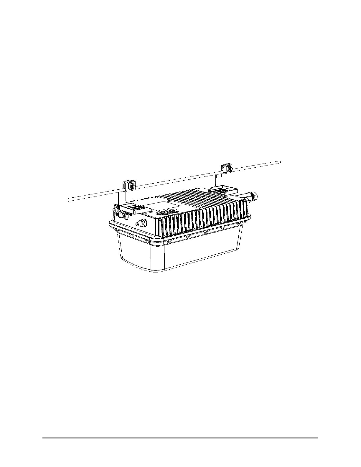
Figure 1. Typical T811-CM mounted on a cable strand
Topics covered in this guide include basic configuration, operation and mounting. The rest
document refers to the strand mount access point with integrated cable modem as the
1
T811-CM AP Installation Guide, 800-71436-001 Rev A
8
About This Installation Guide
Using this Installation Guide
Using this Installation Guide
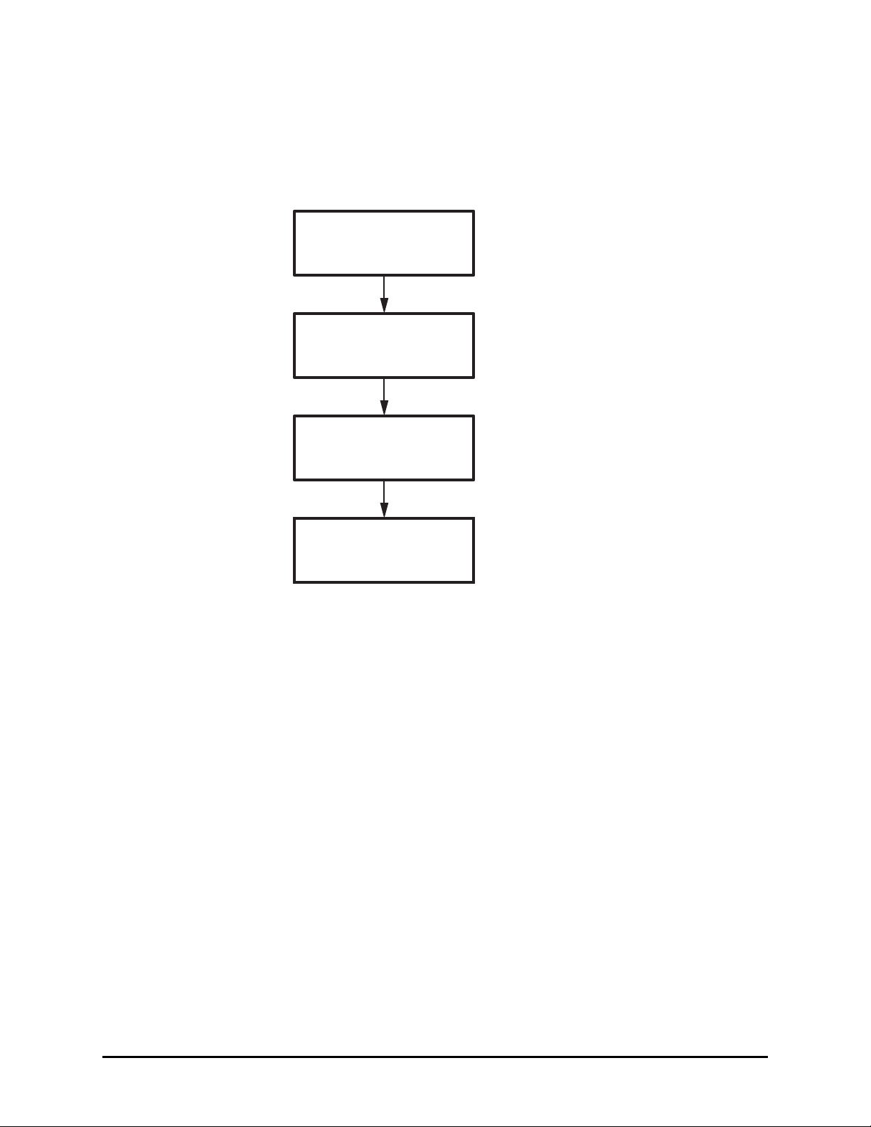
The T811-CM installation is completed with four main steps. Each step includes some substeps.
Figure
2 shows the main steps, and Table 1 includes the substeps.
Figure 2. Adding a T811-CM to an existing Ruckus Wireless network flowchart
Planning
the Installation
Installing
in the Field
Operating and
Troubleshooting
What to Do
Next
T811-CM AP Installation Guide, 800-71436-001 Rev A

9
About This Installation Guide
Using this Installation Guide
Table 1. Adding a T811-CM to an Existing Ruckus Wireless network
Section Heading
2 Planning the T811-CM Installation
• T811-CM Omni Antenna Coverage
• Powering Options
• Performing a Site Survey
3 Installing the T811-CM
• Safety Information
• Unpacking the T811-CM
• Finding the AP and CM MAC Addresses
• Connectors and Ground Point
• LEDs and Reset Button/Diagnostic Ethernet Port
• Dimensions
• Deploying the T811-CM
• Verifying CM and AP Operation
4 Operating and Troubleshooting the T811-CM
• Retrieving the CM’s MAC Address
• Rebooting and Resetting the T811-CM
• How Radio Frequency Scanning Works
5 What to Do Next
• Changing the Administrative Password
• Configuring the Security Settings
• Configuring Advanced Settings and Features
• Reading Related Documentation
T811-CM AP Installation Guide, 800-71436-001 Rev A

10
About This Installation Guide
Terms Used in This Guide
Terms Used in This Guide
Before continuing, Ruckus Wireless recommends that you become familiar with the following terms:
• T811-CM: T811-CM strand mount AP with integrated CM, which includes the AP and CM and
the cable
• AP: The Wi-Fi Access Point part of the T811-CM.
• CM: The Cable Modem part of the T811-CM.
• CMTS: Cable modem termination system high speed data services equipment.
• HFC: Hybrid fiber coax broadband network.
• MSO: Multiple system operator.
Related Documentation
In addition to this guide, each T811-CM documentation set includes the following:
• User Guide: Provides detailed information on how to configure the functions of the unit. The User
Guide is available for download on the Ruckus Wireless Support Web site at
http://support.ruckuswireless.com/documents
• Release Notes: Provides late-breaking information about the current software release, including
new features, enhancements, and known issues. If the information in the Release Notes differs
from the information in this guide, follow the instructions in the Release Notes.
strand interface.
Documentation Feedback
Ruckus Wireless is interested in improving its documentation and welcomes your comments and
suggestions. You can email your comments to Ruckus Wireless at
docs@ruckuswireless.com
When contacting us, please include the following information:
• Document title
• Document part number (on the cover page)
• Page number (if appropriate)
For example:
• T811-CM AP Installation Guide
• Part number: 800-71436-001 Rev A
• Page 11
T811-CM AP Installation Guide, 800-71436-001 Rev A

11
Planning the T811-CM Installation
Before installing the T811-CM, plan the T811-CM installation. In this chapter:
• T811-CM Omni Antenna Coverage
• Powering Options
• Performing a Site Survey
2
T811-CM AP Installation Guide, 800-71436-001 Rev A
12
Planning the T8110-CM Installation
Cable Strand
T811-CM Omni Antenna Coverage
T811-CM Omni Antenna
Coverage
The T811-CM includes internal 5GHz and 2.4GHz omnidirectional antennas, and is equipped with
a
DOCSIS 3.1 cable modem.
The T811-CMs are best deployed where internal-antenna lateral beamforming can provide the
greatest
between APs in a
Figure 4 for a typical
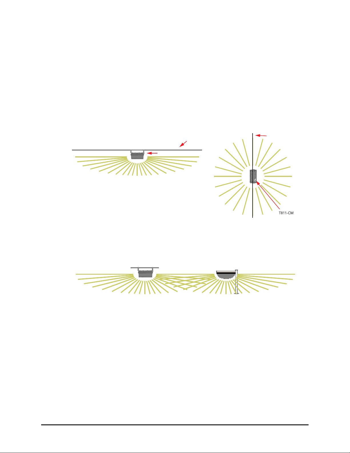
Figure 3. Omni 5GHz and 2.4GHz coverage
Excellent
Figure 4. Typical mesh elevation plane coverage, side view
Excellent
Reach
Reach
reach and throughput to a wide coverage area, and provide the greatest distance
connecting device. See Figure 3 for internal-antenna coverage patterns, and see
mesh coverage pattern between a T811-CM root AP and a 7782 non-root AP.
Cable
Strand
T811-CM
Good Reach
Elevation Plane Coverage
(root AP)
T811-CM
Excellent
Reach
Excellent
Reach
Azimuth Plane Coverage
T610
(non-root AP)
Excellent
Reach
T811-CM AP Installation Guide, 800-71436-001 Rev A

13
Planning the T811-CM Installation
Powering Options
Powering Options
The T811-CM supports AC power over cable (POC). 60 to 90 VAC POC is used when the T811-CM is
powered
via an F-type coaxial cable connected to the HFC cable plant.
Performing a Site Survey
Perform a site survey to determine the optimal T811-CM placement for maximum range, coverage,
and
network performance. Ruckus Wireless Support can supply site survey best practices
information.
The location and orientation that you choose for the T811-CM play a critical role in the
performance of
T811-CM away from
coverage zone is pointing
as described in T811-CM Omni
When performing a site survey, consider the following factors:
• Data rates: Range is generally inversely proportional to data rates. The maximum radio range is
achieved at the lowest workable data rate. Higher data rates are generally achieved at closer
distances.
• Antenna type and placement: Proper antenna configuration is a critical factor in maximizing radio
range. As a general rule, radio range is increased by mounting the radio higher off of the ground
with the AP oriented so that the dome is tilted down. (For recommended orientation examples,
refer to T811-CM Omni Antenna Coverage.)
• Physical environment: Clear or open areas provide better radio range than crowded or filled areas.
The less cluttered the operating environment, the greater the wireless range.
• Obstructions, building materials, and sources of interference: Physical obstructions, such as
concrete pillars, steel beams, buildings and trees, can block or hinder wireless communication.
Avoid installing the T811-CM in an environment where there is an obstruction between sending
and
cranes,
signals.
example,
• Mounting: The T811-CM is designed to clamp onto a 1/4” to 3/8” (6.35mm to 10mm) support
wire.
• Power and backhaul connections: The T811-CM needs a backhaul connection to the CMTS
and it
able to
CM. If SFP backhaul is used, POC will still be used for delivering power over the cable, even if
the data is transmitted over the SFP fiber cable.
When you are finished planning the installation, continue with Installing the T811-CM.
your wireless network. In general, Ruckus Wireless recommends installing the
obstructions and sources of interference and ensuring that the AP’s best
in the general direction of its wireless clients or associated bridge units
Antenna Coverage.
receiving devices. A number of machines and electronic devices that emit radio waves –
wireless phones, microwave ovens, and satellite dishes – interfere with and block wireless
Building materials used in construction also influence radio signal penetration. For
drywall construction permits greater range than concrete blocks.
The hangers allow a 2” bundle of cables between the support wire and the T811-CM.
needs to be close enough to an AC power injector on the CATV cable to assure that it is
pull 60-90VAC. If not, then another power injector must be installed closer to the T811-
T811-CM AP Installation Guide, 800-71436-001 Rev A
Positioning the GPS Antenna
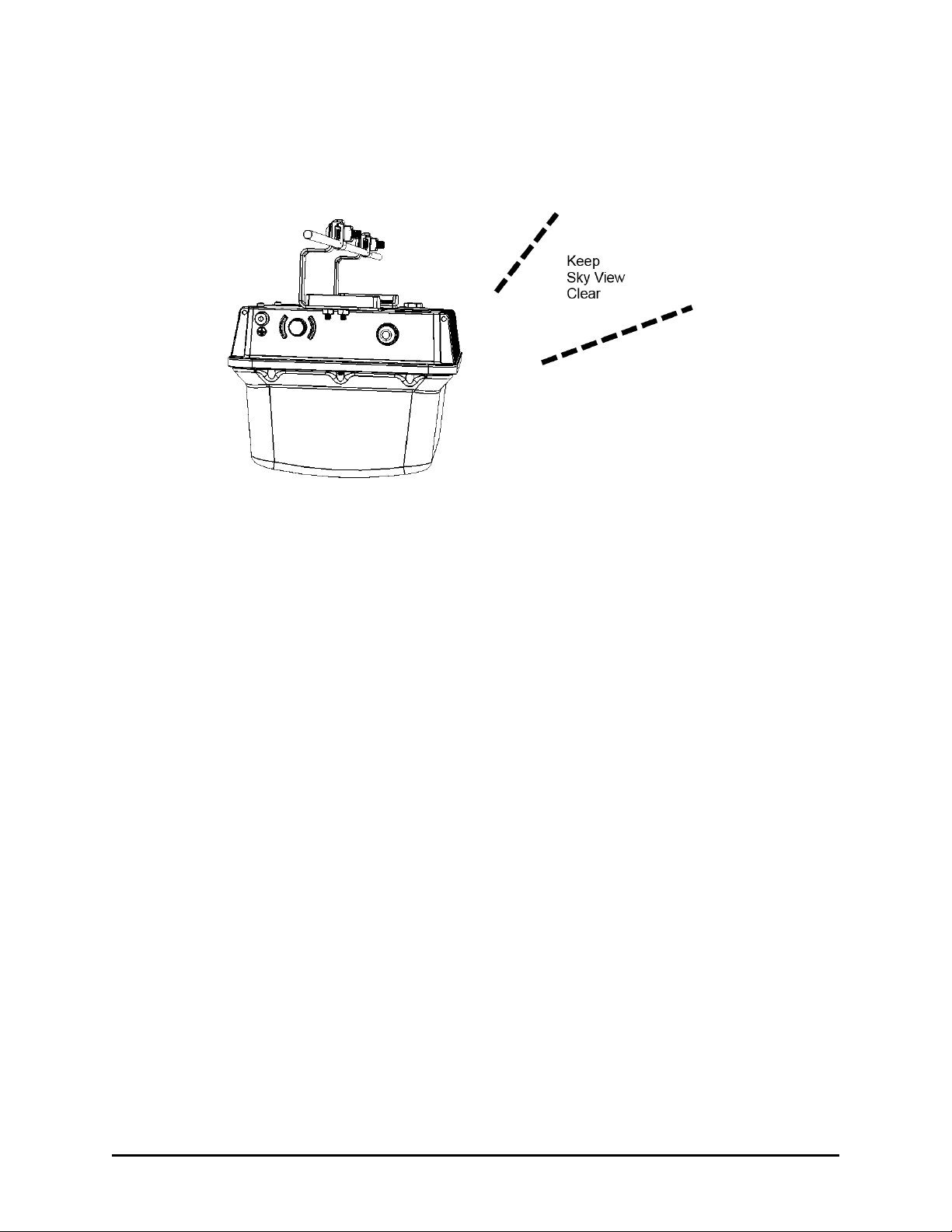
The T811-CM AP includes an internal GPS antenna. If the AP is to be used with the optional
GPS feature enabled, then the GPS antenna must be mounted outdoors and have as clear
a view of the sky as possible (as close as possible to 360 degrees, and with no obstructing
trees or buildings). The GPS antenna must not be installed where it can be covered with
14
Planning the T811-CM Installation
Powering Options
snow buildup to avoid attenuating the GPS signal. These requirements must be met to
ensure that the GPS module can obtain lock and provide accurate GPS time and position.
If the GPS antenna has less than a clear 360-degree view of the sky, then the GPS module
may experience degraded performance.
Fig. 5 T811-CM mounting GPS considerations
T811-CM AP Installation Guide, 800-71436-001 Rev A

15
Planning the T811-CM Installation
Performing a Site Survey
T811-CM AP Installation Guide, 800-71436-001 Rev A

16
Installing the T811-CM
Before installing the T811-CM, Ruckus Wireless recommends that you first complete the
procedures
In this chapter:
• Safety Information
• Unpacking the T811-CM
• AP and CM MAC Addresses, Connectors and Ground Point
• LEDs and Reset Button/Diagnostic Ethernet Port
• Dimensions
• Deploying the T811-CM
• Verifying CM and AP Operation
described in Planning the T811-CM Installation.
3
T811-CM AP Installation Guide, 800-71436-001 Rev A

17
Installing the T811-CM
Safety Information
Safety Information
WARNING! Only trained and qualified installers should be allowed to install, replace, or service this
equipment.
The professional installer is responsible for the proper installation and configuration of this AP. The
AP installation must comply with local regulatory requirements, especially with those regulating
operation near military and/or weather radar systems.
WARNING! Installation of this equipment must comply with local and national electrical codes.
WARNING! Ruckus Wireless strongly recommends that you wear eye protection before mounting
the AP.
CAUTION! Make sure that you form a 80mm - 130mm (3”-5”) drip loop in any cable that is attached
to the AP or other equipment. This will prevent water from running along the cable and entering the
AP or other equipment.
CAUTION! Be sure that grounding is available and that it meets local and national electrical codes.
For additional lightning protection, use lightning rods and lightning arrestors.
CAUTION! Make sure that proper lightning surge protection precautions are taken according to
local electrical code.
T811-CM AP Installation Guide, 800-71436-001 Rev A
 Loading...