

Page 1

BEFORE YOU BEGIN
F G
H
E
A
CB
D
I
J K
Cable gland base
Clamping ring assembly
Rubber O-ring
Sealing nut
Before deploying your Ruckus Wireless T710, verify that all items listed in Package Contents damaged or missing, notify your authorized Ruckus Wireless sales representative. Also, make sure that you have the required hardware and tools.
are included in the package. If any item is
• One safety cable (K in Figure 1)
•This Mounting Guide
Figure 1: T710 field-installation package contents
T710 Access Point
Mounting Guide
CAUTION! THE MINIMUM SOFTWARE REVISION FOR
THE T710 IS ZONEFLEX (ZF) 9.12.2 OR LATER.
DO NOT CONNECT THE T710 TO A RUCKUS
WIRELESS CONTROLLER WITH ZF 9.12.1 OR
EARLIER.
This Mounting Guide provides step-by-step instructions on how to
field-install the Ruckus Wireless ZoneDirector T710 access point (AP).
For detailed information on planning the installation, performing a site
survey, and operating the T710, refer to the ZoneFlex Outdoor Access
Point User Guide, available at https://support.ruckuswireless.com
WARNING: Only trained and qualified personnel should be allowed to
install, replace, or service this equipment.
WARNING: Installation of this equipment must comply with local and
national electrical codes.
CAUTION: Make sure that you form a 80mm - 130mm (3”-5”) drip
loop in any cable that is attached to the AP or the building. This will
prevent water from running along the cable and entering the AP or the
building where the cable terminates.
CAUTION: Be sure that grounding is available and that it meets local
and national electrical codes. For additional lightning protection, use
lightning rods and lightning arrestors.
CAUTION: Make sure that proper lightning surge protection
precautions are taken according to local electrical code.
WARNING: Ruckus Wireless strongly recommends that you wear eye
protection before mounting the T710.
THIS GUIDE IN OTHER LANGUAGES
请从以下网站获得该指南的简体中文版
https://support.ruckuswireless.com
Vous trouverez la version française de ce guide à l'adresse suivante
https://support.ruckuswireless.com
こ の ガ イ ド の⽇本語版 は https://support.ruckuswireless.com
でご覧く ださい。
이 가이드의 한국어 버전은 웹 사이트
(https://support.ruckuswireless.com) 에서 확인하시기 바랍니다 .
Veja a versão em português (Brasil) deste guia em
https://support.ruckuswireless.com.
Puede ver la versión en español (América Latina) de esta guía en
https://support.ruckuswireless.com.
Copyright © 2015 Ruckus Wireless, Inc.
Published November 2015, Part Number 800-70398-001 Rev A
.
.
.
REQUIRED HARDWARE AND TOOLS
• Customer-supplied outdoor-rated three-wire (1-2mm2 or 1418AWG) AC cable
• Customer-supplied earth-ground wire (3-5mm
• 1/2” (13mm) flat-blade screwdriver or equivalent
• No. 2 Phillips screwdriver
• Small flat-blade screwdriver
• Torque wrench or torque screwdriver with sockets
• Long-nose pliers
• Electrical wire stripping and terminal crimping pliers
• Pipe or pole --OR-- a sturdy flat surface
• Electric drill with drill bits and customer-supplied wall anchors, flat
washers, and hex nuts for flat-surface mount
• Two customer-supplied M16 (5/8”) carriage bolts for main
mounting bracket on a wooden pole
• Four customer-supplied 6mm (1/4“) bolts or screws for main
mounting bracket --OR-Four customer-supplied 14mm (1/2“) bolts or screws for main
mounting bracket --OR--
Four factory-supplied 1/2” (12.7mm) wide stainless steel adjustable clamps, 2.5” (63.5mm) diameter, for main mounting bracket
on smaller poles --OR--
Two 7/8” customer-supplied (22mm) wide stainless steel adjustable clamps for main mounting bracket on larger poles
•Ruler
2
or 10-12 AWG)
PACKAGE CONTENTS
A complete T710 field installation package includes all of the items
listed below:
• T710 Access Point (A in Figure 1), includes crimp-type earthground ring terminal
• Two M25 data cable glands (B in Figure 1)
• One main mounting bracket (C in Figure 1)
• One U-joint bracket (D in Figure 1)
• Nine sets 12mm M6 x 1 hex bolt with lock and flat washers
(E in Figure 1)
• One hook bracket (F in Figure 1)
• One set 70mm M8x1.25 hex bolt with spring lock and flat
washers (G in Figure 1)
• One AP attachment bracket (H in Figure 1)
• Four SAE32 steel clamps, 2.5-inch diameter (I in Figure 1)
• One AC power cable input end connector and cap
(J in Figure 1)
The field installation package can also include:
• Service Level Agreement/Limited Warranty Statement
• Regulatory Statement
• Registration card
• Declaration of Conformity, if required
NOTE: This kit can include extra screws, nuts and washers. You may
use the extras wherever required.
STEP 1: CONNECTING AND SEALING THE RJ-45
ABLES
C
The T710 may use zero, or one or two RJ-45 cables, one for Ethernet
when configured as a Root AP (RAP), and one when the T710 is
supplying PoE out to a peripheral device, such as a small cell or micro
cell radio. When the T710 uses RJ-45 cables, connect and seal the
cables using the M25 data cable glands (B in Figure 1).
1 Feed the end of the cable through the sealing nut, rubber O-ring,
clamping ring assembly and cable gland base as shown in Figure
2.
Figure 2: RJ-45 cable and cable gland assembly
2 Use a wide flat-blade screwdriver to remove the required (RESET/
PoE OUT or PoE IN) blanking cap from the T710.
3 Connect the cable to the Ethernet port in the T710.
4 Tighten the cable gland base into the T710 chassis to 7 N.m or
62 in-lbs.
Page 1 of 4
Page 2

5 Wrap the clamping ring assembly around the rubber O-ring. Make
sure that the clamping ring assembly fully encloses the rubber Oring.
6 Seat the clamping ring assembly and rubber O-ring in the cable
gland base.
7 Hand-tighten the sealing nut.
STEP 2: ASSEMBLE THE MOUNTING BRACKET
1 Assemble the Mounting Bracket as shown in Figure 3.
Figure 3: Assemble the mounting bracket
2 Continue with Step 3.
STEP 4: ATTACH THE MOUNTING BRACKET TO A
OLE
P
1 Wrap the steel clamps around the pole, then insert steel clamps
into the clamp slots on the mounting bracket.
Figure 5: Steel clamp slots for a vertical pole
2 Tighten the clamps to 3 N.m or 27 in-lbs, or per manufacturer’s
specifications.
Figure 6: Bracket attached to pole
- 2 (Line/Hot): Black (US), Brown (EU)
- 3 (not used)
NOTE: The color coding of wire conductors varies by region. Before
completing this step, check your local wiring standards for guidance.
5 Using a small screwdriver, tighten the small screws around the
connector housing to fix the connector pins into the terminals.
6 Mate the cable gland with the connector housing, and then hand-
tighten.
STEP 3: ATTACH THE MOUNTING BRACKET TO THE AP
1 Attach the Mounting bracket to the bottom of the AP as shown in
Figure 4.
Figure 4: Use four bolts and lock washers to attach the mounting bracket
Copyright © 2015 Ruckus Wireless, Inc.
Published November 2015, Part Number 800-70398-001 Rev A
3 Continue with Step 5.
STEP 5: POWERING THE AP WITH AC
1 Separate the AC cable connector parts by unscrewing the boot
from the cable gland and the cable gland from the connector
housing.
2 Feed the end of the AC cable through the boot and cable gland.
3 Strip the AC cable as shown.
4 Insert the stripped part of the conductors into the appropriate
terminals on the connector housing. The conductors are colorcoded and must be connected to the appropriate terminals as
shown in Figure 7.
Typical AC wire colors:
- (Earth Ground): Green (US), Green/Yellow (EU)
- 1 (Neutral/Return): White or Gray (US), Blue (EU)
Page 2 of 4
Page 3
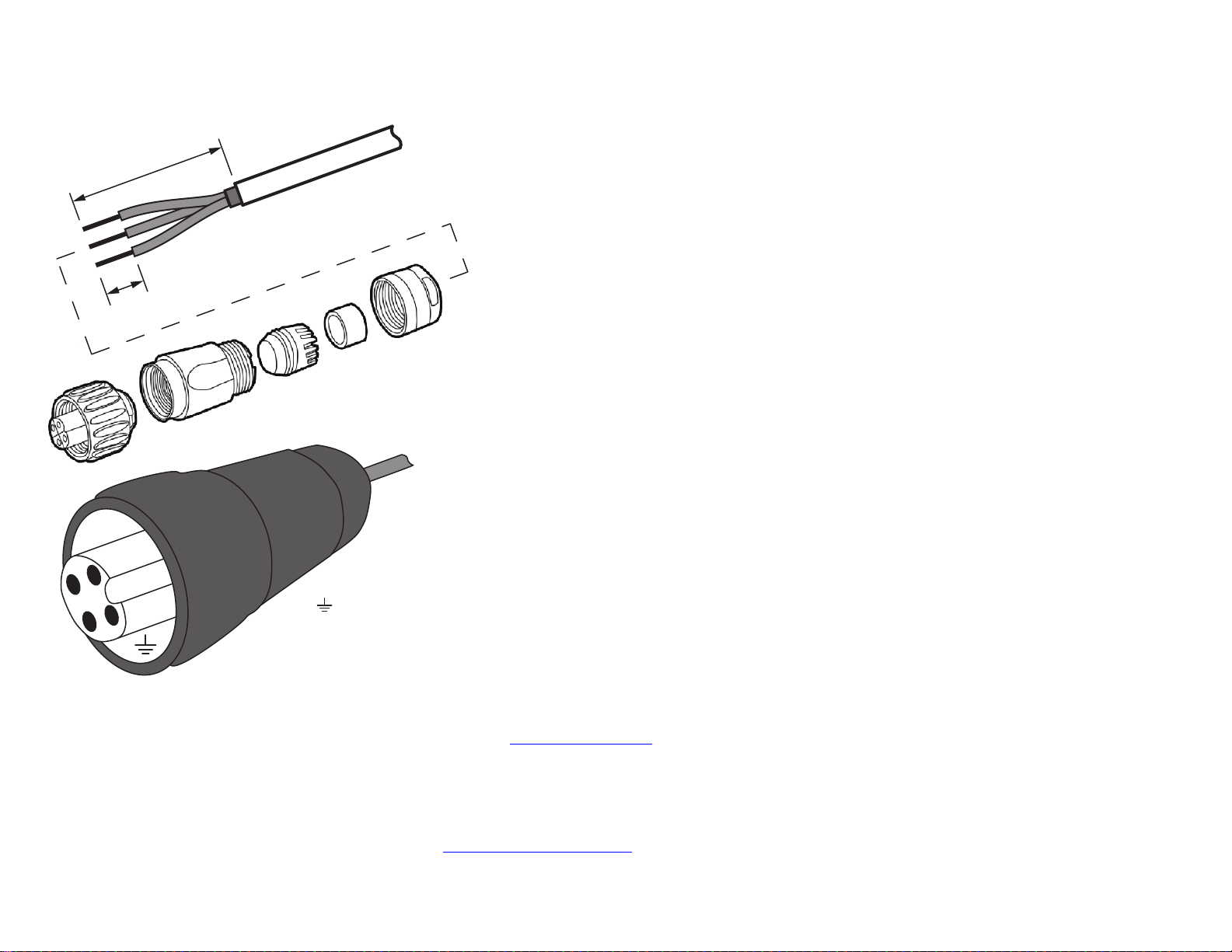
Figure 7: Assembling the AC power connector
36mm or 1.42in (max)
9mm or 0.35in (max)
1
3
2
Earth Ground
Neutral/Return
Line/Hot
(not used)
1
3
2
Wire Stripping Drawn
Actual Size (1:1)
Two different-sized grommets are supplied in the AC connector
assembly kit. Use the grommet that is appropriate to the diameter
of the AC cable that you are using.
7 Mate the boot with the cable gland, and then hand-tighten to seal.
8 Connect the AC cord connector that you have assembled to the
AC power socket on the AP.
9 Connect the AC cord to an AC power source.
CAUTION: If required, you can reset the AP to its factory default
settings by pressing the reset button located inside the PoE OUT/
RESET port. DO NOT DO THIS UNLESS SO INSTRUCTED. (Doing
this resets the T710 IP address to 192.168.0.1.)
Copyright © 2015 Ruckus Wireless, Inc.
Published November 2015, Part Number 800-70398-001 Rev A
NOTE: After a reset, you can access the internal T710 AP web
interface using https://192.168.0.1
other address from 192.168.0.2 through 192.168.0.254, with subnet
mask 255.255.255.0 and default gateway 192.168.0.1. The username
is super, and the password is sp-admin. Refer to the ZoneFlex
SmartCell T710 Outdoor Access Point Installation Guide and the
ZoneFlex Outdoor Access Point User Guide for information on
configuring and operating the T710 AP. Both documents are available
at https://support.ruckuswireless.com
Congratulations! You have mounted the T710 access point.
. Your device must use any
.
TROUBLESHOOTING: REPLACING THE AP FUSES
ONLY IF REQUIRED)
(
NOTE: If the PWR LED does not turn on at all, one or both of the AC
power supply fuses inside the
T710 chassis may have burned out. Replace them as follows:
1 Remove power from the T710.
2 Open the T710 cover and replace any burned-out 5A, 250V, slow-
blow fuse(s), as required.
Figure 8 shows the T710 fuse locations.
Page 3 of 4
Page 4

Figure 8: Fuse locations
Keep Clear
Sky View
3 Make sure that the gasket around the front cover is in its channel.
4 Loosely close the front cover of the T710.
5 Tighten the four front-cover captive screws in the order shown in Figure 9 to 1.7 N.m (15 in-lbs).
6 Retighten the four front-cover captive screws in the order shown to 2.3 N.m (20 in-lbs).
7 Retighten the four front-cover captive screws in the order shown to 2.8 N.m (25 in-lbs).
Figure 9: Front cover screw-tightening pattern
8 Re-apply power to the T710.
You have completed replacing the fuses in the T710.
Copyright © 2015 Ruckus Wireless, Inc.
Published November 2015, Part Number 800-70398-001 Rev A
Page 4 of 4
 Loading...