

Page 1
T310s Access Point
Quick Setup Guide
NOTE: The minimum software revision for the T310s is
ZoneDirector (ZD) 10.1 or later, or SmartZone (SZ) 3.6 or
later, or standalone AP firmware 108.0 or later.
This Quick Setup Guide provides step-by-step instructions on
how to field-install the Ruckus Wireless T310s access point
(AP). For detailed information on planning the installation,
performing a site survey, and operating the T310s, refer to the
Ruckus Wireless Outdoor Access Point User Guide
at https://support.ruckuswireless.com.
WARNING! Only trained and qualified personnel should be
allowed to install, replace, or service this equipment.
WARNING! Installation of this equipment must comply with
local and national electrical codes.
, available
このガイドの日本語版は https://
•
support.ruckuswireless.com でご覧ください。
• 이 가이드의 한국어 버전은 웹 사이트 (https://
support.ruckuswireless.com) 에서 확인하시기 바랍니다.
• Veja a versão em português (Brasil) deste guia em https://
support.ruckuswireless.com.
• Puede ver la versión en español (América Latina) de esta
guía en https://support.ruckuswireless.com.
Before You Begin
Before deploying Ruckus Wireless products, please check for
the latest software and the release documentation.
• Release Notes and other user documentation are available
at http://support.ruckuswireless.com/documents.
• Software upgrades are available at http://
support.ruckuswireless.com/software.
• Open source information is available at http://
opensource.ruckuswireless.com.
• Software license and limited warranty information are
available at http://support.ruckuswireless.com/warranty.
Before deploying your Ruckus Wireless Access Point, verify
that all items listed in
package. If any item is damaged or missing, notify your
authorized Ruckus Wireless sales representative. Also,
make sure that you have the required hardware and tools.
Package Contents
are included in the
• Declaration of Conformity
• Regulatory Statement
• Ruckus Wireless AP Getting Started Guide
• This Quick Setup Guide
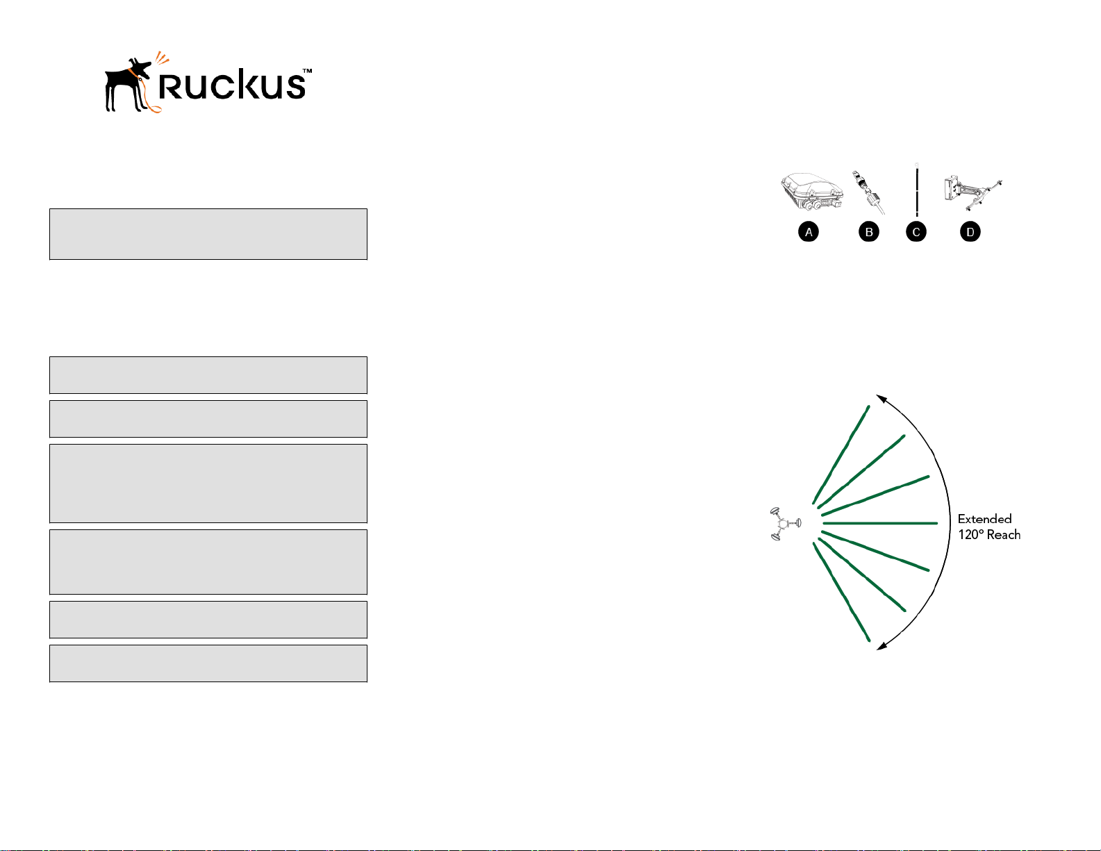
FIGURE 1 T310s Package Contents
T310s Sector Antenna Coverage
The T310s 120-Degree Sector AP is best deployed where
internal antenna directional beamwidths can provide extended
reach and throughput to a 120-degree coverage area. See the
illustrations below for the azimuth and elevation coverage
patterns.
FIGURE 2 Typical AP sector azimuth plane coverage, top view
CAUTION! Make sure that you form a 80mm - 130mm
(3”-5”) drip loop in any cable that is attached to the AP or
the building. This will prevent water from running along the
cable and entering the AP or the building where the cable
terminates.
CAUTION! Be sure that grounding is available and that it
meets local and national electrical codes. For additional
lightning protection, use lightning rods and lightning
arrestors.
CAUTION! Make sure that proper lightning surge protection
precautions are taken according to local electrical code.
WARNING! Ruckus Wireless strongly recommends that you
wear eye protection before mounting the T310s.
This Guide in Other Languages
• 请从以下网站请得请指南的请体中文版 https://
support.ruckuswireless.com.
• Vous trouverez la version française de ce guide à l'adresse
suivante https://support.ruckuswireless.com.
®
Copyright
Published August 2017, Part Number 800-71624-001 Rev A
2017 Ruckus Wireless, Inc. Page 1 of 4
Required Hardware and Tools
• No. 2 Phillips screwdriver
• Small flat-blade screwdriver
• Torque wrench or torque screwdriver with sockets
• Long-nose pliers
• Electrical wire stripping and terminal crimping pliers
• Pipe or pole --OR-- a sturdy flat surface
• Electric drill with drill bits and customer-supplied wall
anchors, flat washers, and hex nuts for flat-surface mount
Package Contents
A complete T310s field installation package includes all of the
items listed below (see Figure below for illustrations):
• T310s Access Point (A)
• M25 data cable gland (B)
• Ground wire with lug (C)
• Pole/Wall Mount Bracket Kit (D)
• Four steel pipe clamps
• Service Level Agreement/Limited Warranty Statement
Page 2
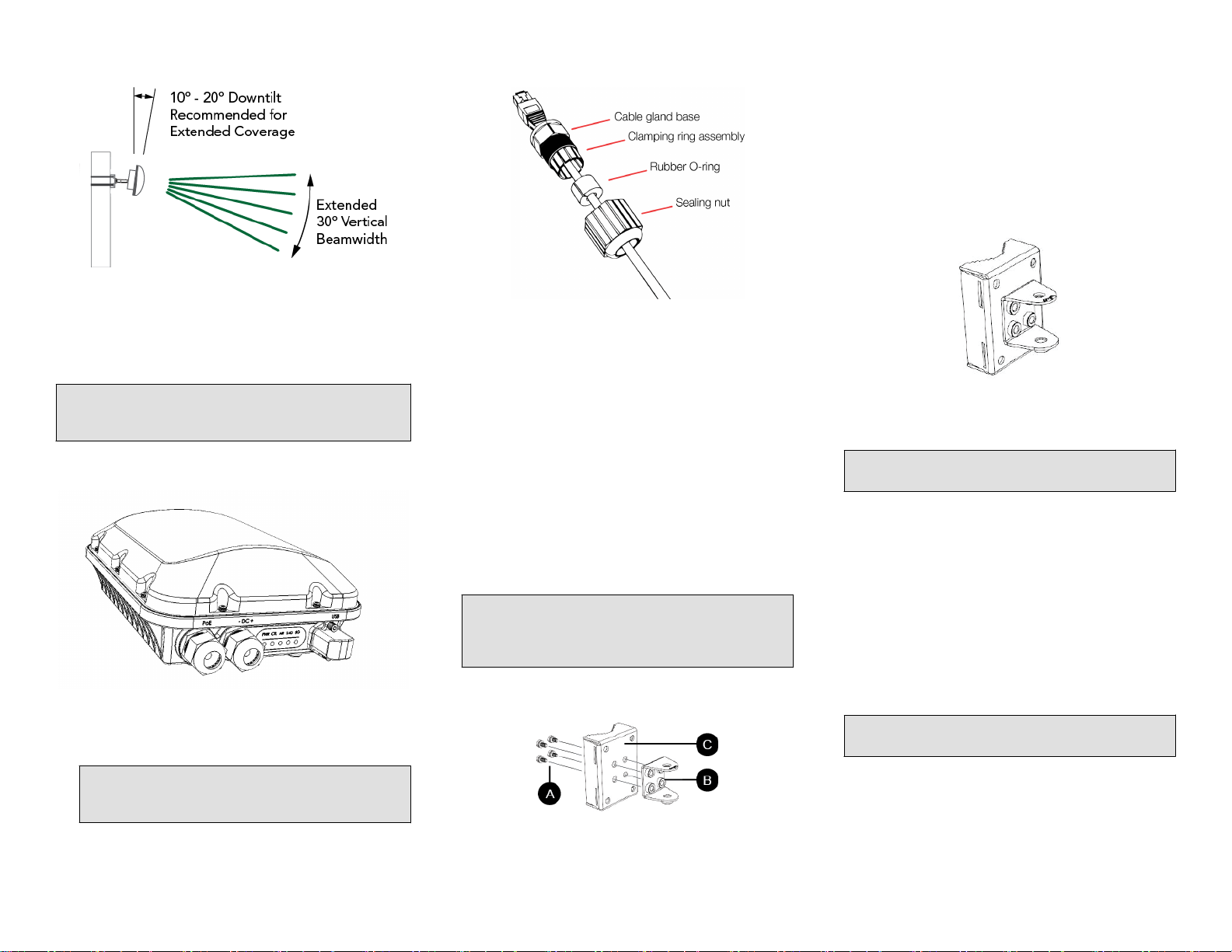
FIGURE 3 Typical AP sector elevation plane coverage, side view
Mounting Instructions
FIGURE 5 RJ-45 cable and cable gland assembly
3. Continue with
Surface
Attaching the Mounting Bracket to a Flat
or
Attaching the Mounting Bracket to a Pole
.
Attaching the Mounting Bracket to a Flat Surface
1. Place the mounting bracket at the location on the flat
surface where you want to mount the AP. Use the holes
on the mounting bracket as a template to mark the
locations of the mounting holes.
FIGURE 7 Mounting bracket flat surface holes
Connecting And Sealing the RJ-45 Cables
Connect and seal the RJ-45 cable(s) using the M25 data
cable glands shown in the Figure below.
WARNING! Do not use any PoE injector not tested and
approved by Ruckus Wireless to power the T310s Access
Point.
FIGURE 4 T310s LEDs and Ports
1. Feed the end of the cable through the sealing nut, rubber
O-ring, clamping ring assembly and cable gland base as
shown.
NOTE: Do not seat the clamping ring and rubber O-ring
into the gland body until the gland body has been
torqued to spec.
2. Use a wide flat-blade screwdriver to remove the required
(PoE IN) blanking cap from the AP.
3. Connect the cable to the Ethernet port on the AP.
4. Tighten the cable gland base into the AP chassis to 7 N.m
or 62 in-lbs.
5. Wrap the clamping ring assembly around the rubber Oring. Make sure that the clamping ring assembly fully
encloses the rubber O-ring.
6. Seat the clamping ring assembly and rubber O-ring in the
cable gland base.
7. Hand-tighten the sealing nut.
Attaching the U-Joint Bracket to the Mounting Bracket
1. Position the U-joint bracket on the mounting bracket.
NOTE: Mount the U-joint bracket in any direction on the
mounting bracket, preferably to allow AP azimuth
adjustments. Then the AP bracket allows AP elevation
adjustments.
FIGURE 6 U-joint bracket attached horizontally to the mounting bracket
2. Remove the mounting bracket from the flat surface.
3. Drill holes required for the mounting hardware.
NOTE: The hardware required for mounting to a wall
are not included in the mounting kit.
4. Attach the mounting bracket to the flat surface using the
mounting hardware.
5. Using the mounting hardware instructions, tighten the
hardware to secure the mounting bracket.
6. Continue with
Joint Bracket
Mounting the Linkage Bracket to the U-
.
Attaching the Mounting Bracket to a Pole
1. Insert the open end of one steel clamp into the upper two
slots on the mounting bracket.
2. Take the other steel clamp and insert it into the lower two
slots on the mounting bracket.
NOTE: The clamps can be daisy-chained together to
accommodate larger poles.
3. Use the clamps to attach the mounting bracket to the
pole. Tighten the clamps to 3 N.m or 27 in-lbs, or per
manufacturer’s specifications.
®
Copyright
Published August 2017, Part Number 800-71624-001 Rev A
2017 Ruckus Wireless, Inc. Page 2 of 4
2. Use four 1/4-28 bolt and washer sets (A) to mount the Ujoint bracket (B) to the mounting bracket (C). Tighten the
bolts to 9.5 N.m (7 ft-lbs).
Page 3

FIGURE 8 Attaching the mounting bracket to a vertical pole
Attaching the AP Bracket to the Linkage Bracket
Attach the AP bracket to the linkage bracket using the
included bolt, nut, lock washer, flat washer, serrated externaltooth washer shown in the illustration below.
The AP bracket attaches to the linkage bracket using an M8
bolt and washer set. The linkage bracket is symmetrical, and
either end can be attached to the AP bracket.
NOTE: Make sure that linkage bracket is installed with its
serrated external-tooth lock washer on the inside of the AP
bracket flanges. This ensures that the elevation adjustment
does not change.
FIGURE 11 Attaching the AP bracket to the AP
4. Continue with
Joint Bracket
Mounting the Linkage Bracket to the U-
.
Mounting the Linkage Bracket to the U-Joint Bracket
1. The linkage bracket attaches to the U-joint bracket using
an M8 bolt and washer set. The linkage bracket is
symmetrical, and either end can be attached to the U-joint
bracket.
NOTE: Make sure that linkage bracket is installed with
its serrated external-tooth lock washer on the inside of
the U-joint bracket flanges. This ensures that the
azimuth adjustment does not change.
2. Loosely assemble the linkage bracket (A), the U-joint
bracket (C), one serrated external-tooth lock washer (B),
and one M8 bolt and washer set (D).
FIGURE 9 Attaching the linkage bracket to the U-joint bracket
As described in
Joint Bracket
linkage bracket using the second serrated external-tooth
lock washer and the second M8 bolt and washer set.
FIGURE 10 Attach the linkage bracket to the AP bracket
Mounting the Linkage Bracket to the U-
, loosely assemble the AP bracket to the
Attaching the AP Bracket to the Access Point
1. Place the AP bracket onto the back side of the AP so that
the four larger screw holes on the bracket align with the
four screw holes on the AP. Make sure that the end of the
AP bracket with the hoisting loop is on the same side as
the AP PoE IN port.
2. Use four 0.5-inch x 0.250-28 hex bolts with split lock and
flat washer sets to mount the AP bracket to the AP.
Tighten the bolts to 2.5-3.0 N.m or 22-27 in-lbs.
CAUTION! Make sure that the screws are no longer
than 0.5 inch. If a screw is longer than 0.5 inch, it can
damage the AP chassis.
3. If required, suspend the AP by attaching a carabiner to
the hoisting loop on the AP bracket.
NOTE: This kit may include extra screws, nuts and
washers. You may use the extras where required.
4. Continue with
Bolt
.
Set the Elevation and Tighten Elevation
3. Set the azimuth required by the AP.
4. Tighten the M8 bolt to 13.6 N-m (10 ft-lbs).
5. Continue with
Bracket
®
Copyright
Published August 2017, Part Number 800-71624-001 Rev A
2017 Ruckus Wireless, Inc. Page 3 of 4
Attaching the AP Bracket to the Linkage
.
Set the Elevation and Tighten the Elevation Bolt
1. Set the elevation required by the AP.
2. Tighten the M8 bolt to 13.6 N-m (10 ft-lbs).
3. Continue with
Powering the AP with DC
.
Page 4

Powering the AP with DC
The T310s can accommodate two sources of power – PoE
(48V) power and 12V DC.
The T310s can draw power from the Ethernet input as a class
3 device, providing a maximum of 12.95W to the system.
Alternately, power can be supplied through a customerprovided 12V DC power supply (7-20V DC acceptable) that
will connect to a two pin terminal block. The terminal block is
accessible through a water-tight gland on one end of the unit.
The terminal block connection has surge and polarity
protection to protect against inserting the wrong polarity leads
into the terminal block.
NOTE: When both 12V DC and the 48V PoE power are
active, the T310s will prioritize the 12VDC power.
NOTE: If DC cables are individual wires, then a special
cable gland insert is required for IP67 seal.
1. Install the DC power supply as described in the DC power
supply accessory installation guide.
2. Connect the power cord to a DC power source.
3. Verify that the PWR LED is a steady green.
Earth Grounding the AP
CAUTION! Make sure that earth grounding is available and
that it meets local and national electrical codes. For
additional lightning protection, use lightning rods and
lightning arrestors.
NOTE: The color coding of ground wires varies by region.
Before completing this step, check your local wiring
standards for guidance.
FIGURE 12 Connect good earth ground to AP here
Congratulations! You have mounted your T310s access point.
Installing a USB Dongle
To install a USB dongle (such as an IoT radio device such as
BLE, 802.15.4, Z-wave or similar), remove the two 3mm hex
screws, remove the cap, and insert the dongle into the USB
port.
Once installed, replace the cap and the hex screws, and
torque the screws to 7 in-lbs (0.79 N.m).
NOTE: If required, a larger USB dongle cap can be
purchased separately. The maximum dimensions of the
USB dongle that can be inserted (with the large USB
dongle cap, part # 902-0127-000) are 6 cm x 2 cm x 1.1
cm. Max Power: 450mW (SiLabs EM3578 max current
draw at +20 dBm is 80mA over a 3.3V rail).
FIGURE 13 Installing a USB dongle
Troubleshooting
CAUTION! If required, you can reset the AP to its factory
default settings by pressing the reset button located inside
the PoE IN port. DO NOT DO THIS UNLESS SO
INSTRUCTED. (Doing this resets the AP IP address to
192.168.0.1.)
NOTE: After a reset, you can access the internal AP web
interface using https://192.168.0.1. Your device must use
any other address from 192.168.0.2 through
192.168.0.254, with subnet mask 255.255.255.0. The
username is super, and the password is sp-admin. Refer to
the
Outdoor Access Point User Guide
configuring and operating the AP. This document is
available at https://support.ruckuswireless.com.
for information on
For More Information
For information on how to configure and manage the AP, refer
to the
Ruckus Wireless Outdoor Access Point User Guide
available from https://support.ruckuswireless.com.
,
Using the factory-supplied ground wire and ground screw/
washer set, connect a good earth ground to the AP chassis
ground point.
CAUTION! The T310s AP includes one 9mm stainless steel
M6x1 earth ground screw with split lock and flat washers.
Make sure that any replacement screw is no longer than
9mm. If a screw is longer than 9mm, it can damage the AP
chassis.
®
Copyright
Published August 2017, Part Number 800-71624-001 Rev A
2017 Ruckus Wireless, Inc. Page 4 of 4
 Loading...