

Page 1

Ruckus Wireless
™
ZoneFlex™ SmartCell™ 8800
(SC8800-S) Outdoor Access Point
Installation Guid e
Part N um ber 800-704 20-001 Rev B
Publishe d Ap ril 2013
www.ruckuswireless.co m
Page 2

Page 3

Contents
1 About this Installation Guid e . . . . . . . . . . . . . . . . . . . . . . . . . . . . . . . . . . . . . . . . . . . . . . . . . 1
Using this Installation Guid e . . . . . . . . . . . . . . . . . . . . . . . . . . . . . . . . . . . . . . . . . . . . . . . 1
Related Documentatio n . . . . . . . . . . . . . . . . . . . . . . . . . . . . . . . . . . . . . . . . . . . . . . . . . . . 3
Documentation Feedback . . . . . . . . . . . . . . . . . . . . . . . . . . . . . . . . . . . . . . . . . . . . . . . . . 3
2 Planning the SC8800-S AP Inst allatio n . . . . . . . . . . . . . . . . . . . . . . . . . . . . . . . . . . . . . . . . . 4
About the AP . . . . . . . . . . . . . . . . . . . . . . . . . . . . . . . . . . . . . . . . . . . . . . . . . . . . . . . . . . . . 4
AP Connectors and LEDs . . . . . . . . . . . . . . . . . . . . . . . . . . . . . . . . . . . . . . . . . . . . . . . . . . 6
Pointing the Internal GPS Antenna . . . . . . . . . . . . . . . . . . . . . . . . . . . . . . . . . . . . . . . . . 10
Performing a Site Survey . . . . . . . . . . . . . . . . . . . . . . . . . . . . . . . . . . . . . . . . . . . . . . . . . 11
Planning the Physical Installation . . . . . . . . . . . . . . . . . . . . . . . . . . . . . . . . . . . . . . . . . . . 12
No tes on Power Sources . . . . . . . . . . . . . . . . . . . . . . . . . . . . . . . . . . . . . . . . . . . . . . . . 12
Decid ing How to Power the AP . . . . . . . . . . . . . . . . . . . . . . . . . . . . . . . . . . . . . . . . . . . 12
3 Preparing the SC8800-S AP at the Depot and Shipp ing to t he Field . . . . . . . . . . . . . . . . 13
Unpacking the AP . . . . . . . . . . . . . . . . . . . . . . . . . . . . . . . . . . . . . . . . . . . . . . . . . . . . . . . 13
Package Cont ents . . . . . . . . . . . . . . . . . . . . . . . . . . . . . . . . . . . . . . . . . . . . . . . . . . . . . . 13
Mounting Kit Contents . . . . . . . . . . . . . . . . . . . . . . . . . . . . . . . . . . . . . . . . . . . . . . . . . . 14
Powering the AP . . . . . . . . . . . . . . . . . . . . . . . . . . . . . . . . . . . . . . . . . . . . . . . . . . . . . . . . 14
Checking LED O peration . . . . . . . . . . . . . . . . . . . . . . . . . . . . . . . . . . . . . . . . . . . . . . . . 14
Configuring the AP for Management by ZoneDirector . . . . . . . . . . . . . . . . . . . . . . . . . 15
Connecting the AP to ZoneDirector . . . . . . . . . . . . . . . . . . . . . . . . . . . . . . . . . . . . . . . 15
Verifying the AP Registration . . . . . . . . . . . . . . . . . . . . . . . . . . . . . . . . . . . . . . . . . . . . . 15
Configuring the AP for Management by FlexMaster or for Standalone Op eration . . 17
Configuring the Administrative Computer . . . . . . . . . . . . . . . . . . . . . . . . . . . . . . . . . . 17
Connecting the AP to the Administrative Comput er . . . . . . . . . . . . . . . . . . . . . . . . . 19
Logging In to the Access Point ’s Web Interface . . . . . . . . . . . . . . . . . . . . . . . . . . . . . 19
Configuring Common Wireless Settings . . . . . . . . . . . . . . . . . . . . . . . . . . . . . . . . . . . 20
Configuring Wireless # Set tings . . . . . . . . . . . . . . . . . . . . . . . . . . . . . . . . . . . . . . . . . . 22
(Optional) Setting the FlexMaster Server Address . . . . . . . . . . . . . . . . . . . . . . . . . . . 23
i
Page 4

Verifying AP O peration . . . . . . . . . . . . . . . . . . . . . . . . . . . . . . . . . . . . . . . . . . . . . . . . . . . 25
Connecting the AP to the N etwork . . . . . . . . . . . . . . . . . . . . . . . . . . . . . . . . . . . . . . . . 25
Associating a Wireless Client with the AP . . . . . . . . . . . . . . . . . . . . . . . . . . . . . . . . . . 26
Checking the TR069 St atus (FlexM ast er Management O nly) . . . . . . . . . . . . . . . . . . . 26
Disconnecting the AP from the Power Source and the Network . . . . . . . . . . . . . . . . 27
Disconnecting the AP from the Administrative Computer . . . . . . . . . . . . . . . . . . . . . 27
Restoring the Ad ministrative Computer’s Network Settings . . . . . . . . . . . . . . . . . . . 27
Shipping the AP to t he Field . . . . . . . . . . . . . . . . . . . . . . . . . . . . . . . . . . . . . . . . . . . . . . 28
4 Installing the SC8800-S AP in the Field . . . . . . . . . . . . . . . . . . . . . . . . . . . . . . . . . . . . . . . . 29
Installation Components and Constraints . . . . . . . . . . . . . . . . . . . . . . . . . . . . . . . . . . . 29
Deploying the Access Point . . . . . . . . . . . . . . . . . . . . . . . . . . . . . . . . . . . . . . . . . . . . . . . 32
Connecting and Sealing the RJ-45 Cables . . . . . . . . . . . . . . . . . . . . . . . . . . . . . . . . . . 33
Preparing the Power Connections . . . . . . . . . . . . . . . . . . . . . . . . . . . . . . . . . . . . . . . . 34
Mounting the Access Point . . . . . . . . . . . . . . . . . . . . . . . . . . . . . . . . . . . . . . . . . . . . . . . 37
Mounting the U-Joint Bracket to the Main Mounting Bracket . . . . . . . . . . . . . . . . . . 39
Attaching the Main Mounting Bracket to a Flat Surface . . . . . . . . . . . . . . . . . . . . . . . 39
Attaching the Main Mounting Bracket to a Wood en Pole . . . . . . . . . . . . . . . . . . . . . 40
Attaching the Main Mounting Bracket to a Metal Pole . . . . . . . . . . . . . . . . . . . . . . . . 42
Mounting the Hook Bracket to the U-Joint Bracket . . . . . . . . . . . . . . . . . . . . . . . . . . 43
Assembling the AP Att achment Bracket and the Access Point . . . . . . . . . . . . . . . . . 44
Attaching the AP Att achment Bracket and AP to the Hook Bracket . . . . . . . . . . . . . 45
Safety-Cabling the AP . . . . . . . . . . . . . . . . . . . . . . . . . . . . . . . . . . . . . . . . . . . . . . . . . . 46
Mounting External Antennas (O pt ional) . . . . . . . . . . . . . . . . . . . . . . . . . . . . . . . . . . . . 48
Verifying Access Point Operation . . . . . . . . . . . . . . . . . . . . . . . . . . . . . . . . . . . . . . . . . . 50
Powering the AP . . . . . . . . . . . . . . . . . . . . . . . . . . . . . . . . . . . . . . . . . . . . . . . . . . . . . . . 50
Connecting the AP to the N etwork . . . . . . . . . . . . . . . . . . . . . . . . . . . . . . . . . . . . . . . . 53
Configuring the Ext ernal Ant enna Gain . . . . . . . . . . . . . . . . . . . . . . . . . . . . . . . . . . . . 54
Associating a Wireless Client with the AP . . . . . . . . . . . . . . . . . . . . . . . . . . . . . . . . . . 59
Checking the TR069 St atus (FlexM ast er Management only) . . . . . . . . . . . . . . . . . . . 59
5 What to Do Next . . . . . . . . . . . . . . . . . . . . . . . . . . . . . . . . . . . . . . . . . . . . . . . . . . . . . . . . . . 60
Changing the Administrative Password . . . . . . . . . . . . . . . . . . . . . . . . . . . . . . . . . . . . . 60
Configuring the Security Settings . . . . . . . . . . . . . . . . . . . . . . . . . . . . . . . . . . . . . . . . . . 60
Configuring Ad vanced Sett ings and Features . . . . . . . . . . . . . . . . . . . . . . . . . . . . . . . . 60
Reading Related Documentation . . . . . . . . . . . . . . . . . . . . . . . . . . . . . . . . . . . . . . . . . . 60
ii
Page 5

Append ix A: Ruckus Wireless-Supplied and Customer-Ordered Parts . . . . . . . . . . . . . . . . . 61
Append ix B: Resetting the Access Point to Factory Default Set tings . . . . . . . . . . . . . . . . . . 65
Append ix C: Installer Mounting Dimensions . . . . . . . . . . . . . . . . . . . . . . . . . . . . . . . . . . . . . . 66
iii
Page 6

iv
Page 7
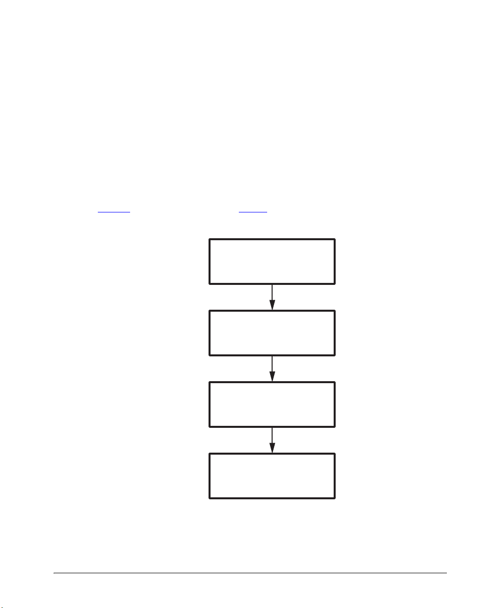
1 About this Installation Guide
Planning
the Installation
Preparing at the Depot
and Sending to the Field
Installing the
SC8800-S in the Field
What to Do
Next
This Installation Guid e provides informatio n on how to add the Ruckus WirelessTM SmartCell™ 8800 Access Point (SC8800-S AP, or AP) to your Ruckus Wireless net work. Topics
covered in this guide include installing, basic configuring, and device mounting.
This guide is intend ed for use by those responsib le for installing and setting up network
equipment. Consequent ly, it assumes a basic working knowled ge of local area networking,
wireless networking, and wireless devices.
Using this Installation Guide
The AP installation is completed with four main steps. Each st ep includes some substep s.
Figure 1 shows the main step s, and Tab l e 1 includes t he substeps.
Figure 1. Adding an SC8800-S AP to an existing Ruckus Wireless net work flowchart
1
Page 8

About this Installation Guide
Using this Installatio n Guide
Table 1. Adding an SC8800-S AP to an Existing Ruckus Wireless network
Section Heading
2
3
4
5
Planning the SC8800-S AP Installation
• About the AP
• AP Connectors and LEDs
• Pointing the Int ernal GPS Ant enna
• Performing a Site Survey
• Planning the Physical Installatio n
Preparing the SC8800-S AP at the Depot and Shipp ing to t he Field
• Unpacking the AP
• Powering the AP
• Configuring the AP for Management by Zo neDirector
• Configuring the AP for Management by FlexMaster or for Standalone
Operation
• Verifying AP Operation
• Shipping the AP to the Field
Installing the SC8800-S AP in the Field
• Installation Components and Constraints
• Deploying the AP
• Mo unting the AP
• Verifying AP Operation
What to Do Next
• Changing the Administrative Password
• Configuring the Security Settings
• Configuring Ad vanced Setting s and Features
• Reading Related Documentation
NOTE: The AP can be managed using an AP web b rowser interface, an AP command line
interface (CLI), and using a simple network management protocol (SNMP) interface, such
as Ruckus Wireless ZoneDirectorTM or FlexMasterTM. This do cument contains configuring
instructions using these interfaces, as appropriate.
2
Page 9

About this Installation Guide
Related Do cumentatio n
Related Documentation
In addition to this guide, each Ruckus Wireless SC8800-S AP documentation set includ es
the follo wing:
■ User Guide: Provides detailed information on how to configure the AP. The ZoneFlex
Outdoor AP User Guide is available for do wnload o n the Ruckus Wireless Sup port Web
site at
https://support .ruckuswireless.com/documents
(login required)
■ Release Notes: Provid es late-breaking information about the current software release,
includ ing new features, enhancements, and known issues. If the information in t he
Release N otes differs from the information in this guide, follow the instructions in the
Release N otes.
■ Online Help: Accessible from the AP’s web interface, the Online Help p rovides
information that helps you config ure the device from the web interface.
Documentation Feedback
Ruckus Wireless is interested in imp roving its documentation and welcomes yo ur
comments and sug gestions. You can email your comments to Ruckus Wireless at
do cs@ruckuswireless.com
When contacting us, please include the following information:
■ Document title
■ Document part number (on the cover page)
■ Page number (if app ropriate)
For example:
■ ZoneFlex SmartCell SC8800-S Out do or Access Point Installation Guide
■ Part number: 800-70420-001 Rev B
■ Page 29
3
Page 10
Planning the SC8800-S AP Installation
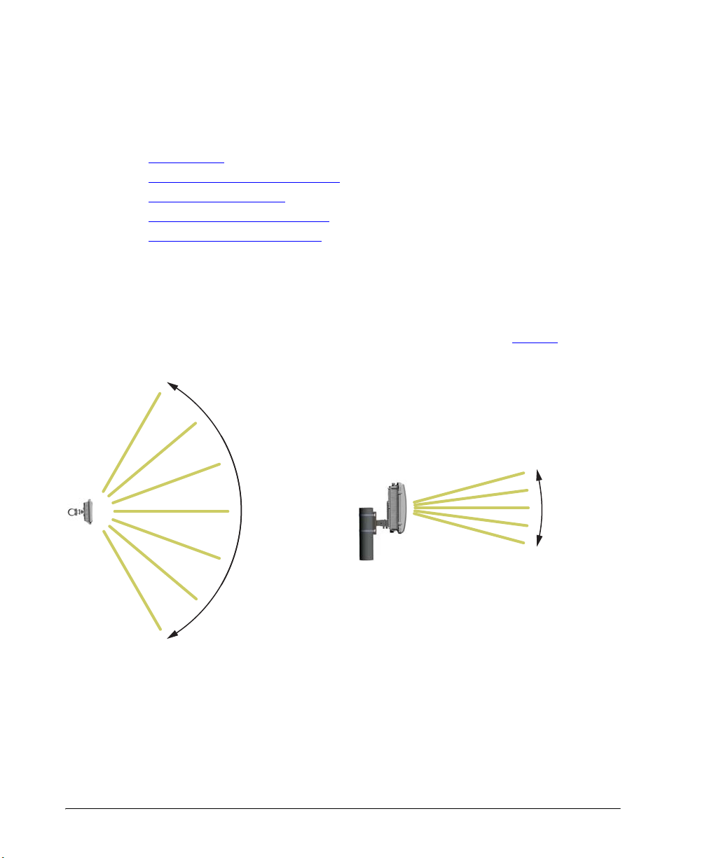
Extended
120º Reach
Azimuth Plane Coverage, Top View
Extended
30º Vertical
Beamwidth
Elevation Plane Coverage
, Side View
About the AP
2 Planning the SC8800-S AP Installation
Before inst alling the SC8800-S AP, it is helpful to verify the version and t o plan the AP
installation:
About the AP
■
■ Pointing the Internal GPS Antenna
■ Performing a Site Survey
■ Planning t he Physical Installation
■ Deciding How to Power t he AP
About the AP
The AP is eq uipp ed wit h 120-Deg ree Secto r 2.4GHz and 5GHz internal antennas, and t hese
antennas can be d eployed where 2.4GHz and 5GHz horizontal beamforming can provide
extended reach and t hroug hput to a 120-degree coverage area. See
Figure 2. Internal antenna 120-Degree sector coverage
Figure 2
.
4
Page 11
Planning the SC88 00-S AP Inst allation
Good Reach
Excellent
Reach
Excellent
Reach
Elevation Plane Coverage, Side View
Azimuth Plane Coverage, Top View
SC8800-S
Panel
Antenna
SC8800-S
Panel
Antenna
About t he AP
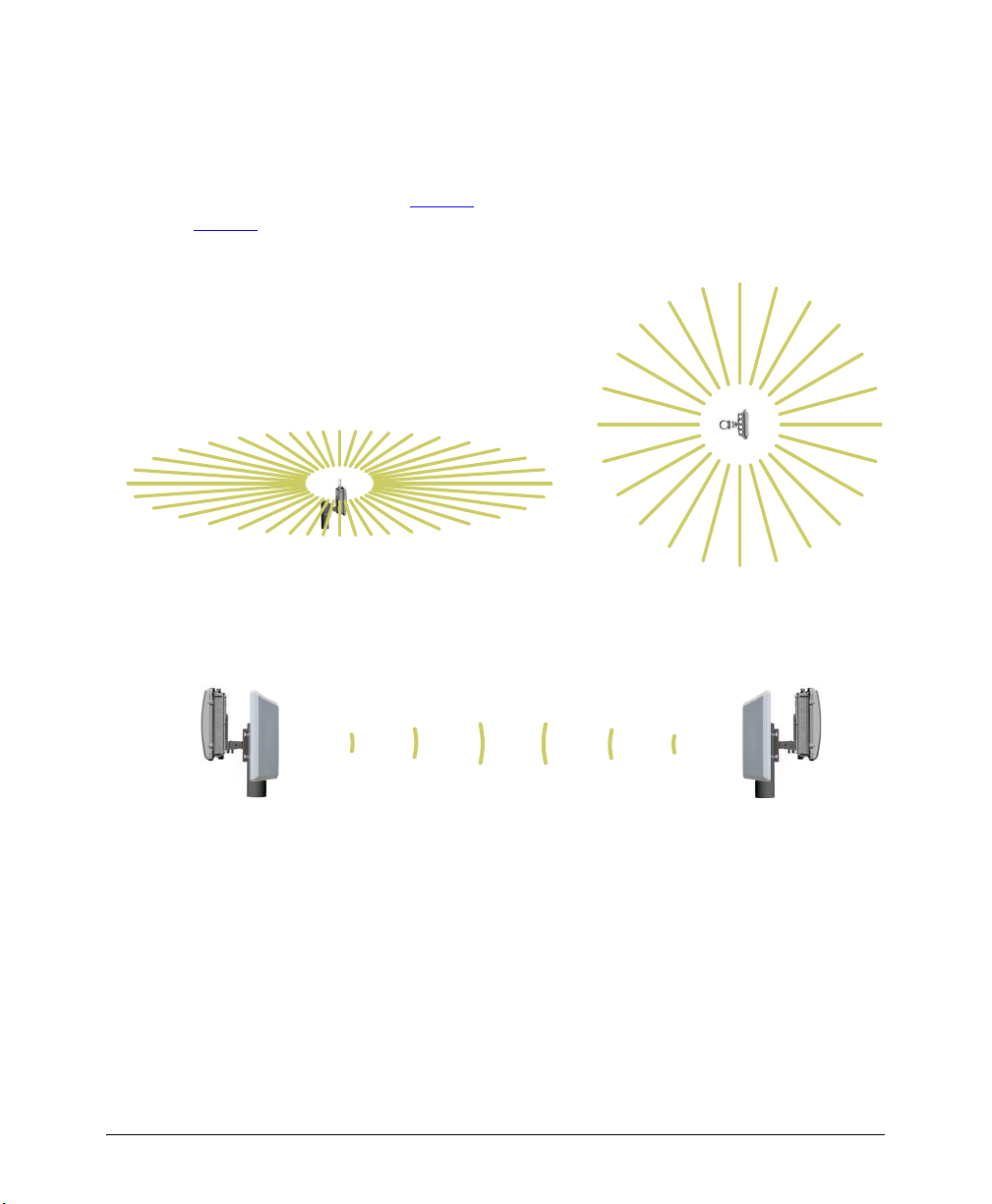
The AP is eq uipped with two 5GHz N-type connectors, which allow operators to use up
to two customer-supplied external 5GHz antennas instead of the internal 5GHz antennas.
These external antennas can support operator-defined coverage areas and point -to-p oint
deployments. For instance,
Figure 3
shows an AP used with omni external antennas, and
Figure 4 shows two APs used in a point-to-point backhaul deployment.
Figure 3. Typical AP omni deployment with an external antenna
Figure 4. Typical AP long-range point-to-point deployment with external antennas
5
Page 12
Planning the SC8800-S AP Installation
1
23
4
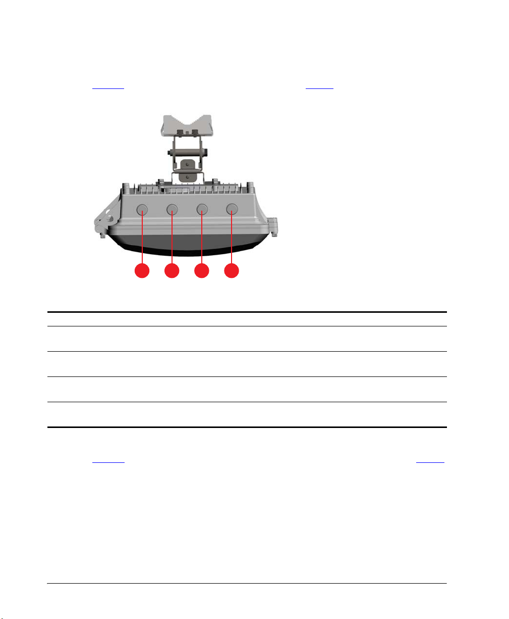
AP Connectors and LEDs
AP Connectors and LEDs
Figure 5 id entifies the top -panel connectors o n the AP. Tab l e 2 describes t hese connecto rs.
Figure 5. Top-panel connect ors
Table 2. Top-panel connectors
No. Label Description
15GHz
ANT 0 p ort
22.4GHz
ANT 2 p ort
32.4GHz
ANT 0 p ort
45GHz
ANT 2 p ort
5GHz 50-ohm N-type connector. Can be used with an external antenna for
op erator-defined coverage areas and point-to-point deployments.
2.4GHz 50-ohm N-type connector. Can be used with an external antenna for
op erator-defined coverage areas and point-to-point deployments.
2.4GHz 50-ohm N-type connector. Can be used with an external antenna for
op erator-defined coverage areas and point-to-point deployments.
5GHz 50-ohm N-type connector. Can be used with an external antenna for
op erator-defined coverage areas and point-to-point deployments.
Figure 6 identifies the AP bottom-p anel connectors and LED locations on the AP. Tab l e 3
describes these connect ors and LEDs.
6
Page 13

Planning the SC88 00-S AP Inst allation
1 2 3
4
5 6
7
AP Connectors and LED s
Figure 6. Bottom-panel connectors and LED locations
Table 3. Bottom-panel connectors
No. Label Description
1 Earth
ground
Use this screw to attach an earth g round to the AP as required b y local
reg ulat io ns.
screw
2AC power
Yo u can use AC to supply po wer to the AP, in add ition to using PoE.
connector
3PoE OUT
RJ45 data
connector
Supports 10/100/1000Mb ps connections and PoE out . If the AP is po wered using
AC or the Ruckus Wireless PoE injector (ordered separately), then this port can
supply 802.3af (15.4W) PoE to a connect ed PoE-capable device (for example, an
IP-based surveillance camera). This port alternatively can supply 802.3at (25.5W)
PoE when used with 20m (65.6 ft.) or shorter CAT5e UTP or better cable.
4RESET
butto n
This button resets the AP to its factory default s, and is mounted under the
RESET/PoE OUT RJ-45 waterproof gland. Refer to
“ App endix B: Resett ing the
Access Point to Factory Default Settings” on page 65 to access the reset but ton
and reset the AP.
5PoE IN
RJ45 data
connector
Supports 10/100/1000Mbp s connections, connects to the net work and receives
Power over Ethernet (Po E) from the Ruckus Wireless 60W PoE inject or. (Refer to
“ Appendix A: Ruckus Wireless-Supp lied and Customer-Ordered Parts” on
page 61 to order a Ruckus Wireless 60W PoE inject or.)
6FIBER p ort This waterproof gland allows you to run a fiber-op tic cable into the SC8800-S
chassis to an optional fiber modem.
7 LEDs See
Figure 7.
7
Page 14
Planning the SC8800-S AP Installation
1
2
3
4
5
AP Connectors and LEDs
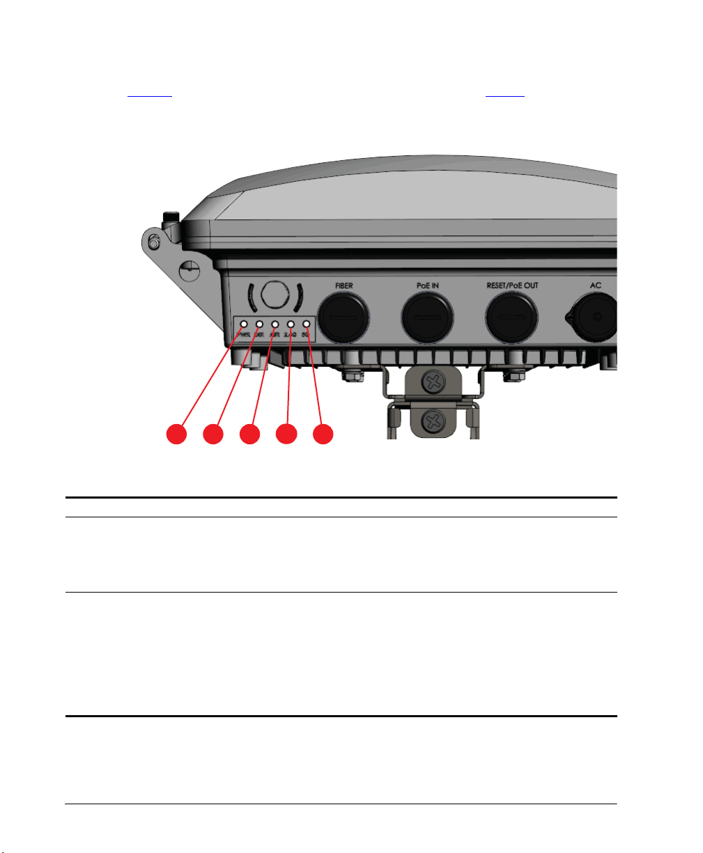
Figure 7 identifies the AP bot tom-panel LED locations on the AP. Tab le 4 describes t hese
connectors and LEDs.
Figure 7. LEDs
Table 4. LED descriptions
No. Label Description
1PWR LED
• Off: No po wer is available, or the AP is not connected to a p ower source.
• So lid Red: The AP is powering on.
• So lid Green: The AP is connected to a power source and has completed its
2DIR LED
• Off: The AP is NOT managed by ZoneDirector (standalone mo de).
• So lid Green: The AP is managed by ZoneDirector and connection to
• Fast Flashing Green (0.5Hz): The AP is managed by ZoneDirector and is
• Slow Flashing Green (2Hz): The AP is managed by ZoneDirector, but is
po wer-on sequence.
ZoneDirector has been established.
currently receiving configuration settings (provisioning ) or a firmware update.
currently unable to communicate with ZoneDirector.
8
Page 15

Table 4. LED descript ions (Continued)
No. Label Description
3AIR LED
• Off: The AP is in standalone mode, or acting as a Root AP if in mesh mode.
• So lid Green: The AP is functioning as a Mesh AP (MAP) and the uplink signal
quality is g ood (>24dBm).
• Fast Flashing Green (0.5Hz): The AP is functioning as a Mesh AP (MAP) and
the wireless signal to its up link AP is fair.
• Slow Flashing Green (2Hz): The AP is in mesh mode, but the AP is still
searching for a mesh uplink.
42.4G LED
• Off: WLAN service is down.
• Amb er (Yellow): WLAN service is up b ut with no client connected .
• So lid Green: WLAN service is up with at least one client connected.
55G LED
• Off: WLAN service is down.
• Amb er (Yellow): WLAN service is up b ut with no clients or downlink M APs
associated /connected.
• So lid Green: WLAN service is up with at least one client is associated. No
do wnlink M APs are connected.
• Fast Flashing Green (0.5Hz): The WLAN is up, at least one downlink MAP is
connected, and at least one client is associated.
• Slow Flashing Green (2Hz): The WLAN is up and at least one d ownlink MAP
is connected. No client s are associated.
Planning the SC88 00-S AP Inst allation
AP Connectors and LED s
9
Page 16

Planning the SC8800-S AP Installation
Keep Clear
Sky View
Pointing the Internal GPS Antenna
Pointing the Internal GPS Antenna
The AP includes an internal GPS antenna. When the AP is to be used with the op tional
GPS feature enabled , the GPS antenna must be mount ed outd oors and have as clear a
view of t he sky as possible (as clo se as possible to 360 degrees, and with no obstructing
trees or building s). The GPS antenna must not be installed where it can be covered with
snow buildup to avo id at tenuating the GPS signal. These requirements must be met to
ensure that the GPS module can ob tain lock and provide accurate GPS time and positio n.
If the GPS antenna has less than a clear 360-deg ree view of the sky, then the GPS module
may experience degraded performance.
Figure 8. GPS Ant enna Locatio n under Radome
Figure 9. Mounted GPS Antenna Position
10
Page 17

Planning the SC88 00-S AP Inst allation
Performing a Site Survey
Performing a Site Survey
Perform a site survey to determine the op timal AP placement or maximum range,
coverage, and network performance. Ruckus Wireless Sup port can supply Site Survey best
practices information.
The location and orientation that you choose for the AP play a critical role in the
performance of your wireless network. In general, Ruckus Wireless recommends installing
the AP away from obstruct ions and sources of interference and ensuring that the AP’s best
coverage zone (refer to
its wireless clients or associated bridg e units.
When p erforming a site survey, consider the following factors:
■ Data rates: Range is generally inversely proportional to data rates. The maximum radio
range is achieved at the lowest workable data rate. Higher data rates will generally be
achieved at closer dist ances.
■ Ant enna type and placement: Prop er antenna configuration is a critical facto r in
maximizing radio range. As a general rule, radio range is increased b y mount ing the
radio higher off of the g round with the AP orient ed so that the dome is facing down
(for recommended orientation examp les, refer to
■ Physical environment: Clear or op en areas p rovide better radio range than closed or
filled areas. The less clut tered the op erating environment, the greater the wireless
range.
■ Obstructions, building materials, and sources of int erference: Physical ob structions,
such as concret e pillars, st eel beams, filing cabinets, build ings and trees, can block or
hinder wireless communicatio n. Avoid installing the AP in an environment where there
is an ob struction between sending and receiving d evices. A number of machines and
electronic devices that emit radio waves, such as cranes, wireless phones, microwave
ovens, and satellite dishes, interfere with and block wireless signals. Building materials
used in const ruction also influence radio signal penetration. For example, drywall
construction permits greater range than concrete blocks.
■ GPS Considerations: If the AP is to be used with the op tional GPS feature enabled ,
then the AP must be mount ed outd oors and have as clear a view of the sky as possible
(as close as possib le to 360 degrees) to help the GPS module obt ain lock and provide
accurate GPS time and position. (Refer to
pag e 10.) The GPS antenna must not be installed where it can be covered wit h snow
buildup to avoid attenuating the GPS signal. If the GPS antenna has less than a clear
360-degree view of the sky, then the GPS module may experience degraded performance.
“ About the AP”
on page 4) is pointing in the general d irection of
“ About the AP”
“ Point ing the Internal GPS Antenna”
on page 4).
on
11
Page 18

Planning the SC8800-S AP Installation
Planning t he Physical Inst allatio n
Planning the Physical Installation
The AP can be installed indoors or outdoors, such as on an interior wall or ceiling, on the
exterior roof overhang of a building, or on a streetlight pole. The GPS antenna must be
installed out doors for proper GPS operation.
Notes on Power Sources
■ The AP only requires one power source (either AC or Po E), but can be powered by AC
and PoE at the same time.
■ The AP may be po wered by AC power or by PoE input using an Ruckus Wireless 60W
PoE injector (part number 902-0180-XX00, where XX is the country code).
■ PoE OUT supports 802.3af (15.4W output) loads when the AP is operating off AC input
po wer or when operating off the PoE input port using a high-p ower 60W PoE Injector.
■ When AC powered and PoE is present, the AP draws power from the AC connection.
■ The AP PoE O utput supports high power periphe ral d evic es up to 25W, suc h as a small
cell or micro cell radio b ut only with the fo llow restrict ions: the PoE Output cable lengt h
between the AP and peripheral device is less t han 8m (25 feet) and that the AP is
op erating off of AC Input power. High-power peripherals (up to 25W) may also be
po wered b y an AP operating from the PoE Inp ut using a high power 60W injector,
provided that the PoE input cable length between the injector and AP is less than 8m
(25 feet) and that the DC voltage at the AP Po E input connector is at least 44 VDC.
Deciding How to Power the AP
The AP can be p owered using eit her AC power and/or Power over Ethernet (PoE). Use this
info rmation and the information in
to determine how to power the AP.
AC Power
Ruckus Wireless supplies an AC power cable connector with the AP. The custo mer supplies
the country-specific 3-wire AC power cable. The supported inp ut voltages are 90-264 VAC
at 50/60Hz.
The APs used in a mesh network generally use AC power.
Power over Ethernet
The customer orders a Ruckus Wireless 60W PoE injector (p art number 902-0180-XX00,
where XX is the country code).
The AP can be po wered by 60W PoE to sup po rt 802.3at PoE Out to 27W. 802.3at (25.5W)
PoE can be supported with 8m (25 ft.) or short er CAT5e UTP or better cable, and an 8m
(25 ft.) or shorter CAT5e UTP or better input cable. When AC powered and PoE is present,
the AP d raws p ower from the AC connection.
“ Installation Components and Const raints” on page 29
12
Page 19

Preparing t he SC880 0-S AP at the Depot and Shipping to the Field
Unpacking the AP
3 Preparing the SC8800-S AP at the Depot
and Shipping to the Field
■ Unpacking the AP
■ AP Connectors and LEDs
■ Powering the AP
■ Configuring the AP for Management b y ZoneDirector
■ Configuring the AP fo r Management b y FlexMaster or for Standalone Operation
■ Verifying AP O peration
■ Shipping the AP to the Field
Unpacking the AP
1. Open the ZoneFlex SC8800-S package, and t hen carefully remo ve the contents.
2. Return all packing materials to the shipping box, and put the box away in a dry location.
3. Verify that all items listed in
includ ed in the package. Check each item for d amage. If any item is damaged or
missing, notify your authorized Ruckus Wireless sales representative.
“ Package Contents” and “ Mounting Kit Contents” are
NOTE: “ Appendix A: Ruckus Wireless-Supplied and Customer-Ord ered Parts” on
pag e 61 includes pictures and descriptions of these and ot her facto ry-orderable and
customer-supplied parts.
Package Contents
A complete SC8800-S AP package contains all of the items listed below:
• SC8800-S Outdoor Access Point
• O ne AC power cable input end connector and cap
• Two M 25 data cable g lands
• Service Level Ag reement /Limited Warranty St atement
• Regulato ry Statement
• Registration card
• Declaration of Conformity
• This Inst allatio n Guide
• M ounting kit (refer to
“ M ounting Kit Cont ents”
for d etails)
13
Page 20

Preparing the SC880 0-S AP at the Depot and Shipping to the Field
Powering the AP
Mounting Kit Contents
NOTE: “ Appendix A: Ruckus Wireless-Supplied and Customer-Ord ered Parts” on
pag e 61 includes pictures and descriptions of these and ot her facto ry-orderable and
customer-supplied parts.
• M ain mounting bracket (1 piece)
• U-Joint Bracket (1 piece)
• Small 10mm M6 x 1 Hex Bolt with Lock and Flat Washers (9 sets)
• Hook Bracket (1 piece)
• Large 70mm M8x1.25 hex bolt with sp ring lock and flat washers (1 set)
• AP At tachment Bracket (1 piece)
• SAE32 steel clamps, 2.5-inch diameter (4 pieces)
Powering the AP
NOTE: You only need to connect one type of power source at this point, even if you are
planning to use both PoE and AC power in your final deployment.
Apply power to the AP using one of these two methods:
•
“ Powering the AP with AC” on page 51
• “ Po wering the Access Point with PoE” on p age 52
Checking LED O peration
Perform a sp ot-check using the LEDs to verify that the AP is operating normally. When the
AP is operating no rmally and no wireless clients are associated with it:
■ The PWR LED is g reen.
■ The 2.4G and 5G LED shows slow blinking green. This indicates that there are no
wireless clients connected to the AP’s WLAN services.
You have checked the LED operation. Continue with
by ZoneDirector” on page 15 or “ Configuring the AP for M anagement by FlexMaster or
for Stand alone O peration” on p age 17.
“ Configuring t he AP for Management
14
Page 21

Preparing t he SC880 0-S AP at the Depot and Shipping to the Field
Configuring the AP for Management by ZoneDirector
Configuring the AP for Management by
ZoneDirector
1. Collect required equipment and information:
• O ne Cat5e or bett er Ethernet cable.
• M AC add ress (12 alphanumeric digits) from the outside of the AP case.
2. Verify that the AP is powered on as described in
Connecting the AP to ZoneDirector
NOTE: In addition to using Layer 2 auto discovery to enable the Access Po int to register
with Zo neDirector, you can also use DHCP Opt ion 43 or DNS. For more information, refer
to the ZoneDirector User Guide.
3. If you are powering the AP wit h PoE, then cont inue with Step 4. If you are powering
the AP with AC, then continue with
4. Connect one end of the Et hernet cable to the Data In port on the PoE injector.
5. Connect the ot her end of the Ethernet cable to the same Layer 2 subnet as
ZoneDirector. The same Layer 2 subnet means that there should not be any rout er
between the AP and Zo neDirector.
The AP auto matically discovers and registers with ZoneDirector.
6. You have comp leted connecting the AP to ZoneDirector. Continue with
7. Connect one end of the Et hernet cable to the PoE IN p ort on the AP.
8. Connect the ot her end of the Ethernet cable to the same Layer 2 subnet as
ZoneDirector. The same Layer 2 subnet means that there should not be any rout er
between the AP and Zo neDirector.
The AP auto matically discovers and registers with ZoneDirector.
9. You have comp leted connecting the AP to ZoneDirector. Continue with
St ep 7.
“ Powering the AP” on page 14.
St ep 10
St ep 10
.
.
Verifying the AP Registration
10. Log in to ZoneDirector, and then go to the M onitor > Access Points page.
11. Look for the M AC add ress of the AP, and then in the Actio n column click the Allow
icon. This allows t he AP to register with ZoneDirector.
When t he Status column shows Connected, this indicates t hat the AP has successfully
registered with ZoneDirector.
15
Page 22

Preparing the SC880 0-S AP at the Depot and Shipping to the Field
Configuring the AP for M anagement by ZoneDirector
NOTE: If the ZoneDirector is set to Enable Mesh, it automatically assig ns the AP as a Roo t
AP.
Cont inue with “ Verifying Access Point Op eration” on p age 50.
16
Page 23

Preparing t he SC880 0-S AP at the Depot and Shipping to the Field
Configuring the AP fo r Management b y FlexMaster or for St andalone Operation
Configuring the AP for Management by FlexMaster
or for Standalone Operation
1. Collect required equipment and information:
• An administ rative computer (notebook comp uter) running Windows 7/Vista/XP/
2000 with one wireless 802.11b/ g/ n network card and one Ethernet card installed .
• M ozilla Firefox 2.0 (or later) or Microsoft Internet Explorer 6.0 (o r later) installed on
the administrative computer.
• O ne Cat5e or bett er Ethernet cable.
• M AC add ress (12 alphanumeric digits) from the outside of the AP case.
NOTE: You may need to disable the firewall between the AP and the FlexMaster server
to complete this procedure.
2. Verify that the AP is powered on as described in “ Powering the AP” on page 14.
3. Continue with “ Configuring the Administrative Comp uter” on p age 17.
Configuring the Administrative Computer
NOTE: The following procedure is applicable if the administrative computer is running
Windows XP or Windows 7. If you are using a different operating system, refer to the
do cumentation that was shipped with your op erating system fo r information on how to
modify the comp uter’s IP address settings.
1. On your Windows 7 or Windows XP computer, open the N etwork Connections (or
Network and Dial-up Connections) control panel according to how the Start menu is
set up:
• O n Windows 7, click Start > Control Panel > Network and Internet > Network
and Sharing Center > Change Adapter Settings.
• O n Windows XP, click St art > Control Panel > Network Connect ions.
2. When the Network Connections window appears, right-click the icon fo r Local Area
Connection, and then click Properties.
NOTE: Make sure that you configure the Local Area Connection properties, not the
Wireless Network Connection properties.
3. When the Lo cal Area Connect ion Prop erties dialog box appears, select Internet
Protocol (TCP/IP) or TCP/IPv4 in Windows 7 from the scrolling list, and then click
Properties. The Internet Prot ocol (TCP/IP) Properties dialog box ap pears.
17
Page 24

Preparing the SC880 0-S AP at the Depot and Shipping to the Field
Configuring the AP for Management by FlexMaster or for Standalone Operation
4. Write down all of the current ly active network settings. You will need this information
later when you restore your computer t o its current network config uration.
5. Click Use the following IP address, and then configure the IP address settings with
the values listed in
. For a samp le configuration, refer to Figure 10.
Tab le 5
Table 5. Configure your comput er’s IP add ress settings
IP address 192.168.0.22 (or any address in the 192.168.0.x network—with the
exception of 192.168.0.1, which is the default IP address assigned to
the Access Point)
Subnet mask 255.255.255.0
Note: You can leave the Default Gateway and DNS server fields b lank.
Figure 10. Samp le configuration in the Int ernet Protocol (TCP/IP) Propert ies dialog box
6. Click OK to save your changes and close the TCP/IP Prop erties dialog box.
7. Click OK again to close t he Local Area Connection Properties dialog box.
Windows saves the IP address setting s that you have configured. Continue with
“ Connecting the AP to the Administrative Comp uter” on page 19.
18
Page 25

Preparing t he SC880 0-S AP at the Depot and Shipping to the Field
Configuring the AP fo r Management b y FlexMaster or for St andalone Operation
Connecting the AP to the Administrative Computer
1. Verify that the AP is powered on as described in “ Powering the AP” on page 14.
2. If you are powering the AP wit h PoE, then cont inue with
the AP with AC, then continue with
3. Connect one end of the Et hernet cable to the Data In port on the PoE injector.
4. Connect the ot her end of the Ethernet cable to the administrative computer either
directly or through a hub.
5. You have completed connecting the AP t o the administrative computer. Continue with
“ Log ging In to the Access Po int’s Web Interface”
6. Connect one end of the Et hernet cable to the PoE IN p ort on the AP.
7. Connect the ot her end of the Ethernet cable to the administrative comput er.
8. You have completed connecting the AP t o the administrative computer. Continue with
“ Log ging In to the Access Po int’s Web Interface”
St ep 6.
St ep 3. If you are powering
on p age 19.
on p age 19.
Logging In to the Access Point’s Web Interface
1. In the address or lo cation bar, type the following add ress:
https://192.168.0.1
2. Press <Enter> on the keyboard to connect to the AP’s web interface. A security alert
message appears.
3. Click Ye s or OK or Proceed anyway (depending on the browser) to cont inue. The AP’s
login page appears.
Figure 11. The ZoneFlex Access Point login page
4. In Username, type super.
5. In Password, type sp-admin.
6. Click Login. The web interface appears, disp laying the Status > Device page.
7. Continue with
“ Configuring Common Wireless Settings”
on page 20.
19
Page 26

Preparing the SC880 0-S AP at the Depot and Shipping to the Field
Configuring the AP for Management by FlexMaster or for Standalone Operation
Configuring Common Wireless Settings
The settings on the Common tab are required to enable wireless d evices to associate with
the AP. The default wireless settings on the AP are listed in Tab le 6 .
Table 6. Default wireless sett ings
Setting Default Value
SSID (network name) Wireless 1 to Wireless 8 (8 WLANs)
Encryption (security) Disabled on all WLANs
Default management IP add ress 192.168.0.1
NOTE: The AP has one 2.4GHz radio and one 5GHz rad io. The wireless settings for each
radio need to be configured sep arately on the web interface. To configure the 2.4GHz
radio sett ings, click Configuration > Radio 2 .4G. To configure the 5GHz radio settings,
click Configuration > Radio 5G.
1. On the left menu of the web interface, click Configuration > Radio {2.4/5} G. The
Common page appears (Figure 12).
Figure 12. The Configuration > Radio 2.4 > Common tab
2. Verify that the common wireless settings are configured as list ed in Tab l e 7.
20
Page 27

Preparing t he SC880 0-S AP at the Depot and Shipping to the Field
Configuring the AP fo r Management b y FlexMaster or for St andalone Operation
Table 7. Common wireless configuration
Setting Recommended Value
Wireless Mode
• 2.4 GHz (802.11b/ g/ n) for Configuration > Rad io 2.4G > Common.
• 5GHz (802.11a/n) for Configuration > Radio 5G > Common.
Channel SmartSelect.
Channel Width 20 M Hz.
Count ry Code
• If you purchased the AP in the United States, this value is fixed to
United States at the factory and is not user configurable.
• If you purchased the AP outside the United States, verify that the
value is set to your country or region. Selecting the correct country
code ensures that the AP uses only the radio channels allowed in
your country or reg ion.
Note: The t wo radios on the Zo neFlex AP are always configured with
the same country cod e setting. If you change the country cod e for
Radio 2.4G, for example, the same change will be automatically
applied to Radio 5G.
3. If you made any changes to the Common t ab, then click Updat e Settings.
4. Continue with “ Configuring Wireless # Settings” on page 22.
21
Page 28

Preparing the SC880 0-S AP at the Depot and Shipping to the Field
Configuring the AP for Management by FlexMaster or for Standalone Operation
Configuring Wireless # Settings
The settings on at least one W ireless # tab are required to enable wireless d evices to
associate with the AP.
1. Click one of the Wireless # tabs. The selected Wireless # pag e appears (
Figure 13. The Configuration > Radio 2.4 > Wireless 1 tab
Figure 13).
2. In Wireless Availability, click Enabled.
3. In Broadcast SSID, click Enabled.
4. Clear the SSID b ox, and then type a unique and descriptive name that you want to call
this wireless network.
For example, you can type Ruckus Wireless AP. This SSID is the name that help s
users identify this wireless network in their wireless network connection app lication.
NOTE: You may also configure other wireless settings on this and ot her Wireless # tabs
(in addition to the settings described above), although it is not necessary for completing
the AP inst allation.
5. Click Update Settings. You have completed configuring the basic wireless setting s of
the AP.
22
Page 29

Preparing t he SC880 0-S AP at the Depot and Shipping to the Field
Configuring the AP fo r Management b y FlexMaster or for St andalone Operation
If you are configuring the AP for management by FlexMaster, then cont inue wit h
“ (Optional) Setting the FlexMaster Server Ad dress” on page 23. If you are configuring the
AP for standalone operation, then continue with “ Disconnecting the AP from the Admin-
istrative Computer” on page 27.
(Optional) Setting the FlexM aster Server Address
If you have a FlexMaster server installed on the network and you intend to use FlexMaster
to manage the AP, you can set the FlexMaster server address at this p oint . Before starting
this p rocedure, make sure yo u obtain the correct FlexMaster server URL.
NOTE: In additio n to setting the FlexMaster server URL manually on the AP, you can also
use DHCP Op tion 43 or DNS to point the AP to the FlexMaster server. For more
information, refer to the FlexMaster User Guide.
1. Navigate to Administrat ion > M anagement (Figure 14).
2. Scroll down t he page to the TR069 / SN M P Management Choice section.
Figure 14. Type the FlexMast er server URL
3. Verify that the Auto option is selected.
23
Page 30

Preparing the SC880 0-S AP at the Depot and Shipping to the Field
Configuring the AP for Management by FlexMaster or for Standalone Operation
4. In FlexMaster Server URL, type the URL of the FlexMaster server on t he network. You
can use either http or https to connect to the URL and include either t he host name
or IP add ress of the FlexMast er server in the URL. The following are examples of valid
FlexMaster server URLs:
http://flexmaster/intune/server
https://flexmaster/intune/server
http://192.168.20.1/intune/server
https://192.168.20.1/intune/server
5. Click Update Settings to save your changes. You have completed sett ing the
FlexMaster server address on the AP.
NOTE: Instructions on how to verify that the AP and FlexMaster can communicate with
each other are provid ed in
page 26.
on
“ Checking the TR069 Status (FlexMaster Management O nly)”
6. Continue with “ Verifying AP O peration” on page 25.
24
Page 31

Preparing t he SC880 0-S AP at the Depot and Shipping to the Field
Verifying AP O peration
Verifying AP Operation
Ruckus Wireless recommends that you verify that the AP is operating correctly.
NOTE: You can perform these verification tasks ind oors.
To verify that the AP is operating correctly, perform the following procedures:
Connecting the AP to the Network
■
■ Associating a Wireless Client with the AP
■ Checking the TR069 Status (FlexMaster Management Only)
■ Disconnecting the AP from the Power Source and the Net work
■ Disconnecting the AP from the Administrative Comp uter
■ Restoring the Administrative Computer’s Network Settings
Connecting the AP to the N etwork
This proced ure assumes that you have already assembled an AC cord connector as
describ ed in
60W PoE injector available as described in “ Powering the Access Point with PoE” on
pag e 52.
“ Powering the AP with AC” on page 51, or that you have a Ruckus Wireless
NOTE: You only need to connect one type of power source at this point, even if you are
planning to use both PoE and AC power in your final deployment.
The AP can connect to the netwo rk using data cables, or can connect t o the network using
wireless backhaul if it is p art of a mesh network.
NOTE: If the ZoneDirect or is set t o Enable M esh, ZoneDirect or automatically assigned
the AP as a Root AP while “ Configuring the AP for M anagement by ZoneDirector” on
pag e 15.
1. If the AP is part of an available mesh network, cont inue wit h St ep 2. If the AP is using
AC power, then continue with Step 4. If the AP is using PoE, then continue with Step 6.
2. When the AP has been configured as Root AP, and is powered up and does not find a
wired connection back to its ZoneDirector, it automatically looks for another Root AP.
When it find s another AP in the mesh network, it auto matically provisions itself as a
Mesh AP in the mesh network.
3. Continue with
“ Associating a Wireless Client with the AP” on page 59.
4. Connect the Ethernet cable from your network’s router or switch t o the PoE IN port on
the AP.
25
Page 32

Preparing the SC880 0-S AP at the Depot and Shipping to the Field
Verifying AP O peration
5. Continue with
6. Connect the Ethernet cable from the Data In port on the PoE injector to your network’s
router or switch.
7. Continue with
“ Associating a Wireless Client wit h the AP” on page 59.
“ Associating a Wireless Client wit h the AP” on page 59.
Associating a Wireless Client with the AP
1. In the client device's wireless interface, select t he SSID config ured in the
Wireless # Settings” on page 22 section.
2. Connect the client device to the selected WLAN SSID.
3. After the wireless client successfully connects to the wireless LAN, cont inue wit h
“ Checking the TR069 St atus (FlexM aster M anagement Only)” on page 26 or
“ Disconnecting the AP from the Power Source and the Network” on p age 27.
“ Configuring
Checking the TR069 Status (FlexM aster M anagement Only)
If you configured the AP to report t o a FlexMaster server on the network (see
Setting the FlexMaster Server Address” on page 23), then make sure you verify that the
AP can successfully communicate with the FlexMaster server. You can do this by checking
the TR069 st atus on the AP’s web interface.
1. In the AP’s web interface, go to the Administ ration > Management p age.
2. Scroll down t o the TR069 Status section.
3. Check the value for Last successful contact. If it sho ws a date in green, then the AP was
able to communicate successfully with FlexMaster.
4. Continue with
pag e 27.
“ Disconnecting the AP from the Power Source and the Network” on
“ (Op tional)
26
Page 33

Preparing t he SC880 0-S AP at the Depot and Shipping to the Field
Verifying AP O peration
Disconnecting the AP from the Power Source and the Network
1. Disconnect the AP from the power source (either from the PoE inject or or AC power
source).
2. Verify that the PWR LED is off.
3. Disconnect the Et hernet cable that runs to the AP’s PoE IN RJ45 port from your
network’s router or swit ch.
4. Continue with
“ Disconnect ing the AP from the Ad ministrative Computer” on page 27.
Disconnecting the AP from the Administrative Computer
1. If not already do ne, disconnect the AP from the power source (either from the AC
po wer source or PoE injector).
2. Verify that the PWR LED is off.
3. Disconnect the Et hernet cable from the administrative computer’s Ethernet port.
4. Continue with “ Restoring the Administrative Comput er’s Network Setting s” on
pag e 27.
Restoring the Administrative Computer’s N etwork Settings
If the administrative computer’s network settings were changed as described in
uring the Administrative Computer” on page 17 and you do not want to change the
network settings back now, then continue with “ Shipping the AP to the Field” on page 28.
If you do want to change the net work settings back now, continue wit h the following steps:
NOTE: You may need to enable the firewall between t he AP and the FlexMaster server
to complete this procedure.
1. On your Windows 7 or Windows XP computer, open the Network Connections (or
Network and Dial-up Connections) control panel according to how the Start menu is
set up:
• In Windo ws 7, click Start > Control Panel > Net work and Internet > Network and
Sharing Cent er > Change adapter settings.
• In Windows XP, click Start > Control Panel > Network Connectio ns.
2. When the Network Connections window ap pears, rig ht-click the icon for Local Area
Connection, and then click Properties.
“ Config-
27
Page 34

Preparing the SC880 0-S AP at the Depot and Shipping to the Field
Shipping the AP to the Field
3. When the Lo cal Area Connect ion Prop erties dialog box appears, select Internet
Protocol (TCP/IP) from the scrolling list, and then click Properties. The TCP/ IP
Properties d ialog box appears.
4. Restore the computer’s network settings by typing the original IP address setting s in
the TCP/IP Prop erties dialog box.
5. On the TCP/ IP Properties dialog box, click O K to close it.
6. Click OK again to close t he Local Area Connection Properties dialog box.
Yo u are now ready to ship t he AP. Continue with
Shipping the AP to the Field
Aft er you have prep ared the AP as described earlier in this section, repackage the AP and
its mounting kit in the original shipping container and ship it t o its final installation site.
Cont inue with
“ Installing the SC8800-S AP in the Field” on p age 29.
“ Shipping the AP to the Field”
on page 28.
28
Page 35

Inst alling the SC880 0-S AP in the Field
Installatio n Comp onents and Constraints
4 Installing the SC8800-S AP in the Field
Before inst alling the AP, Ruckus Wireless recommends that you first complet e the procedures described in “ Planning the SC8800-S AP Installation” on p age 4 and “ Preparing the
SC8800-S AP at the Depot and Shipping to the Field ” on p age 13. Completing these
procedures ensures that the AP installation has been planned, and that the AP has been
prepared fo r installation.
Cont inue with the following proced ures:
Installation Components and Constraints
■
■ Dep loying the Access Point
■ Mounting the Access Point
■ Verifying Access Point Op eration
Installation Components and Constraints
■ The AP can be inst alled indoors or outdo ors, such as on an interior wall or ceiling, on
the exterior roof overhang of a build ing, or on a streetlight pole.
■ Refer to
Refer to Figure 16 for the comp onents involved in a typical outdoor AC installation.
No te which components must be installed indo ors and outdoors.
■ Ruckus Wireless strongly recommend s 80mm - 130mm (3” -5” ) drip loop s on any cables
that are installed out doors (for example, on an outdoor AP).
■ The AP can be powered using either AC p ower and/or Po wer over Ethernet (PoE).
• AC Power: An AC power cable connector is supplied with the AP. The customer
• Power over Ethernet: The customer orders a Ruckus Wireless Po E inject or (part
■ The APs used in a mesh network generally use AC power.
Figure 15 for the components involved in a typical out door PoE inst allation.
supplies the country-specific 3-wire AC power cable. The supported inp ut volt ages
are 90-264 VAC 50/60Hz.
numb er 02-0180-XX00, where XX is the country code).
NOTE: The AP only requires one power so urce (either AC or PoE, but can be p owered
by AC and PoE at the same t ime.
- The AP can be powered by 60W PoE to support 802.3af Po E Out to 15.4W.
- The AP can be powered by 60W PoE t o support 802.3at PoE Out to 27W. 802.3at (25.5W)
PoE can be supported with 20m (65.6 ft.) or shorter CAT5e UTP or better cable.
- When AC powered and PoE is present, the AP d raws power from the AC connection.
WARNING: Only trained and qualified personnel should be allo wed to install, rep lace,
or service this eq uipment.
29
Page 36

Inst alling the SC8800-S AP in the Field
Indoor
Router
or switch
Cat5 Ethernet
cables
Surge
protector
Outdoor
Drip
loop
Drip
loop
Ground
rod
screw
Outdoor-rated
Cat5e UTP cable
5.5mm
2
(10AWG)
min solid-core wire
ZoneFlex
SC8800-S
Outdoor AP
AC cable
PoE
injector
Installation Comp onents and Constraints
WARNING: Inst allation of t his equip ment must comply with local and national electrical
codes.
CAUTION : M ake sure t hat you fo rm a 80mm - 130mm (3” -5” ) drip lo op in any cab le that
is att ached to the AP or the building. This will prevent water from running along the cable
and ent ering the AP or the building where t he cable terminates.
CAUTION : Be sure that ground ing is available and that it meets local and national
electrical codes. For additio nal lightning protection, use lightning rods and lightning
arrestors.
.
CAUTION : M ake sure t hat proper lightning surge protection precautions are taken
according to local electrical cod e.
Figure 15. Typical outdoor PoE installation components
Ground
30
Page 37

Inst alling the SC880 0-S AP in the Field
Indoor
Router
or switch
Cat5 Ethernet
cable
Surge
protector
Outdoor
Drip
loop
Drip
loops
AC power
source
Ground
rod
Ground
screw
Outdoor-rated
Cat5e UTP cable
5.5mm
2
(10AWG)
min solid-core wire
AC cable
ZoneFlex
SC8800-S
Outdoor AP
Installatio n Comp onents and Constraints
Figure 16. Typical outdoor AC installation components
31
Page 38

Inst alling the SC8800-S AP in the Field
Deploying the Access Point
Deploying the Access Point
In this sectio n, you will mount the AP in its final mount ing location and verify its op eratio n.
Perform the following:
Connecting and Sealing the RJ-45 Cables
■
■ Preparing the Power Connections
■ Attaching the M ain Mounting Bracket to a Flat Surface
■ Attaching the M ain Mounting Bracket to a Met al Pole
■ Assembling the AP Attachment Bracket and the Access Point
■ Attaching the AP At tachment Bracket and AP to the Hook Bracket
■ Safety-Cabling the AP
■ Mounting External Ant ennas (Optional)
■ Powering the AP
■ Connecting the AP to the Network
■ Configuring the External Antenna Gain
■ Associating a Wireless Client with the AP
■ Checking the TR069 Status (FlexMaster Management only)
32
Page 39

Inst alling the SC880 0-S AP in the Field
Cable gland base
Clamping ring assembly
Rubber O-ring
Sealing nut
Deploying the Access Point
Connecting and Sealing the RJ-45 Cables
The AP comes with t wo sets of waterproof RJ-45 cable glands. To complet e this procedure,
you will need an RJ-45 cab le and a cable gland.
1. Take out one of the plastic bags containing a cable g land.
2. Feed the end of the cable through the sealing nut, rubb er O-ring, clamp ing ring
assemb ly and cable gland base as shown in
Figure 17. Cable and cab le gland assembly
Figure 17.
3. Remove the required (RESET/PoE OUT or PoE IN) blanking cap from the SC8800-S.
Figure 6 for cap location.)
(See
4. Connect the cable to the ethernet port in the SC8800-S.
5. Hand-tighten the cable gland base into the SC8800-S chassis.
6. Wrap t he clamping ring assembly around the rubber O -ring. Make sure that the
clamping ring assembly fully encloses the rubb er O-ring.
7. Seat the clamping ring assembly and rubber O-ring in the cable gland base.
8. Hand-tighten the sealing nut
You have complet ed connecting and sealing the cable. Rep eat this procedure as required
for the ot her cables.
33
Page 40

Inst alling the SC8800-S AP in the Field
Deploying the Access Point
Preparing the Power Connections
The AP sup ports both AC power and PoE and it can be connected to b oth power so urces
at the same time. If you want use both power sources, comp lete these power connect ions
using both of these two methods:
Preparing the AC Power Connection
•
• Preparing the PoE Power Connection
Preparing the AC Power Connection
1. Collect required tools and supplies:
• An outdoo r-rated three-wire (1-2mm2 or 14-18AWG) AC cable that is long enough
to connect the AP with the AC power source.
• A wire st ripper.
• A pair of long-nose pliers.
• A small screwd river.
• A ruler (for measuring the stripped portion of the AC cable).
2. Remove the small plastic bag that contains the AC cable connect or from the AP
package.
3. Separate t he AC cable connector parts by unscrewing the boot from the cable gland
and the cable g land from the connect or housing. See
Figure 18.
34
Page 41

Figure 18. Assemb ling the AC power connector
36mm or 1.42in (max)
9mm or 0.35in (max)
1
3
2
Earth Ground
Neutral/Return
Line/Hot
(not used)
1
3
2
Wire Stripping Drawn
Actual Size (1:1)
Inst alling the SC880 0-S AP in the Field
Deploying the Access Point
4. Feed the end of the AC cable through the boot and cable gland.
5. Strip the AC cable as shown in
6. Insert the st ripped part of the conductors into the app ropriate terminals on the
connector ho using. The cond uctors are color-cod ed and must be connected to the
appropriate terminals as shown in
Figure 18.
Figure 18. Refer to Tab le 8 for typical AC wire colors.
35
Page 42

Inst alling the SC8800-S AP in the Field
Deploying the Access Point
Table 8. Typical AC wire colors
Terminal Color
(Earth Ground) Green (US), Green/Yellow (EU)
1 (N eutral/Return) Whit e or Gray (US), Blue (EU)
2 (Line/ Hot) Black (US), Brown (EU)
3 (not used)
Note: The color coding of wire cond uctors varies by region. Before complet ing this st ep,
check your local wiring standards for guidance.
7. Using a small screwdriver, tig hten the small screws around the connector housing to
fix the connector pins into the terminals.
8. Mate the cable g land with the connector housing, and t hen tighten.
NOTE: Two different-sized grommets are supplied in the AC connecto r assemb ly kit. Use
the grommet that is appropriate t o the diameter of the AC cable that you are using.
9. Mate the boot with the cable gland, and then tighten to seal.
10. Connect the AC cord connecto r that you have assembled to the AC power socket on
the AP.
WARNING: Do not app ly power to the AP at this p oint . You should connect the AP t o a
po wer source only after you finish connect ing all other components included in
“ Verifying
Access Point Op eratio n” on page 50.
You have prepared the AC power connection.
Preparing the PoE Power Connection
1. Obtain a Ruckus Wireless 60W PoE injector. (Refer to
Supplied and Customer-Ordered Parts” on p age 61 to order a Ruckus Wireless 60W
PoE injector.)
2. Obtain one outd oor-rated and one indo or-rated Cat5e or better Ethernet cable.
3. Connect one end of the out door-rated Ethernet cable to the Data Out/Power Out port
on the PoE injector, and then connect the other end to the PoE IN port on the AP.
WARNING: Do not app ly power to the AP at this p oint . You should connect the AP t o a
po wer source only after you finish connecting all other components in
Point Operation” on page 50.
Yo u have prepared the PoE power connection.
“ Appendix A: Ruckus Wireless-
“ Verifying Access
36
Page 43

Inst alling the SC880 0-S AP in the Field
1
2
3
4
5
6
Mo unting the Access Point
Mounting the Access Point
The AP package includes a mounting b racket kit shown in Figure 19. The kit components
are described in Tab l e 9.
Figure 19. AP Mounting Bracket Exploded Assembly
37
Page 44

Inst alling the SC8800-S AP in the Field
Mo unting the Access Point
Table 9. AP Mounting Bracket Kit Description
No. Interface Element Description
1 Main Mounting
Bracket
2 U-Joint Bracket Attaches to Main Mounting Bracket wit h four Small M6 Bolt
3 Small M6 Bolt and
Washer Sets
4 Hook Bracket Attaches to U-Joint Bracket with one Large M8 Bolt and
5 Large M8 Bolt and
Washer Set
6 AP Att achment
Bracket
Mounting bracket for use on flat surfaces and poles.
Designed for use with the following fasteners:
• Two M16 (5/ 8” ) carriage bolts for wooden poles
(customer-supplied).
• Four 6mm (1/4“ ) b olt s or screws (customer-sup plied).
• Four 14mm (1/2“ ) bolts or screws (customer-supplied).
• Four 1/2” (12.7mm) wide stainless steel adjustable
clamps, 2.5” (63.5mm) diameter, for smaller poles
(factory-supp lied ).
• Two 7/8” (22mm) wide stainless steel adjustable clamps
for larger poles (customer-supplied).
and Washer Sets.
Nine sets of M 6 hex bolt, 10mm M6 x 1 with spring lock and
flat washers. Attaches U-Joint Bracket to Main M ount ing
Bracket, attaches AP Att achment Bracket to AP, and
attaches safety cable to AP At tachment Bracket.
Washer Set. Allows up t o 30
º elevation upt ilt or downtilt.
Attaches to AP Att ach Bracket wit h two captive screws.
One set of M 8 hex bolt, 70mm, M8x1.25, with spring lock
and flat washers.
Mounts on the back of the AP using four Small M6 Bolt and
Washer Sets. Att aches to the Ho ok Bracket wit h two Hook
Bracket captive screws.
To mount the AP:
1. Collect the following items:
• Bracket mounting kit (see
Figure 19)
If you are mounting the AP on a flat surface, then you will also need:
• An electric drill with drill bits
• Customer-supplied wall anchors, flat washers, and hex nuts
If you are mounting the AP on a pipe or pole, then you will also need:
• A pipe or pole
• O ther mount ing hardware and to ols as d escribed in
Tab le 9
2. Continue with “ Mounting the U-Joint Bracket to the M ain Mounting Bracket” on
pag e 39.
38
Page 45

Inst alling the SC880 0-S AP in the Field
1
2
3
Mo unting the Access Point
Mounting the U-Joint Bracket to the Main M ounting Bracket
1. Posit ion the U-joint bracket on the main mount ing bracket. (Note the orientatio n.)
Figure 20. U-Joint Bracket Attached Horizontally to the Main Mounting Bracket
Table 10. Main Mounting Bracket and U-Joint Bracket
No. Description
1 Main Mounting Bracket
2 U-Joint Bracket
3 Small M6 Bolt and Washer Sets
2. Use four small M6 bolt and washer sets to mount the U-joint bracket to the main
mounting bracket. Tighten the bolts to 9.5 N.m (7 ft-lb s).
3. Continue with
“ Att aching the Main Mounting Bracket to a Wooden Pole” on page 40, or “ Attaching
the Main Mounting Bracket to a Metal Pole” on page 42.
“ Attaching the Main Mounting Bracket to a Flat Surface”
on page 39 or
Attaching the M ain M ounting Bracket to a Flat Surface
The main mounting bracket can be attached to a flat surface using small or large b olt s or
screws as describ ed in
WARNING: Ruckus Wireless strongly recommends that you wear eye protection b efore
drilling holes in the mount ing surface.
1. Place the main mounting bracket at the location on the mounting surface where you
want to mount the AP.
2. Use the holes on the main mounting bracket as a temp late to mark the locations of
the mount ing holes.
Tab le 9.
39
Page 46

Inst alling the SC8800-S AP in the Field
1
2
UP
Mo unting the Access Point
Figure 21. Flat Surface Mounting Hole Lo cations
Table 11. M ain Mo unting Bracket Flat Surface Holes
No. Interface Element Description
1 Large Holes (4 places) Designed for use with four customer-sup plied 14mm (1/2“ )
2 Small Holes (4 places) Designed for use with four customer-sup plied 6mm (1/4“ )
3. Remove the main mounting bracket from the mount ing surface.
4. Drill holes required for the mounting hardware (see
op tio ns).
5. Attach the main mounting bracket to the flat surface using the mounting hardware.
No te the UP direction.
6. Using the mounting hardware instructions, tig hten the hardware to secure the main
mounting bracket.
7. Continue with
“ M ounting the Hook Bracket to the U-Joint Bracket”
bo lts or screws.
bo lts or screws.
Tab le 9 fo r mounting hardware
on page 43.
Attaching the M ain M ounting Bracket to a Wooden Pole
The main mo unting bracket can be attached t o a wooden pole using carriage bolts as
describ ed in
WARNING: Ruckus Wireless strongly recommends that you wear eye protection b efore
drilling holes in the pole.
1. Place the main mounting bracket at the location on the mounting surface where you
want to mount the AP.
2. Use the square holes o n the main mounting b racket as a temp late to mark the locations
of the mounting holes.
Tab le 9
.
40
Page 47

Inst alling the SC880 0-S AP in the Field
1
UP
Mo unting the Access Point
Figure 22. Woo den Pole Mounting Hole Locations
Table 12. Main Mounting Bracket Carriage Bolt Holes
No. Interface Element Description
1Square Holes
(2 places)
3. Remove the main mounting bracket from the pole.
4. Drill holes for the carriage bolts as required by the local pole owner.
5. Attach the main mounting bracket to the flat surface using the carriage bolts. Note the
UP d irection.
6. Using carriage bolt nuts, tighten the carriage bolts as required by the local pole owner
to secure the main mounting bracket.
7. Continue with
“ M ounting the Hook Bracket to the U-Joint Bracket”
Designed for use with two customer-supp lied M16 (5/8” )
carriage b olt s.
on page 43.
41
Page 48

Inst alling the SC8800-S AP in the Field
1
2
UP
1
2
UP
Mo unting the Access Point
Attaching the M ain M ounting Bracket to a Metal Pole
The main mounting b racket can be att ached t o a metal p ole using st ainless st eel adjustable
clamps as described in Tab l e 9.
1. Insert the open end of one steel clamp into the upp er two slot s on t he main mounting
bracket.
Figure 23. Adjustable Clamp Slots for a Vertical Pole
Table 13. Main M ounting Bracket Adjustable Clamp Slots
No. Interface Element Description
1 Small Slots (4 places) Designed for use with two or four factory-sup plied 1/2”
2 Large Slots (4 places) Designed fo r use with two customer-supplied 7/8” (22mm)
(12.7mm) wide stainless steel adjustable clamp s, 2.5”
(63.5mm) diameter, fo r smaller poles.
wide st ainless steel adjustable clamps for larger poles.
2. Take the other st eel clamp and insert it into t he lower two slot s on the main mo unting
bracket.
3. Use the clamps to att ach the main mounting b racket to the pole (see Figure 24). No te
the UP direction. Tighten the clamps to 1.1-1.2 N.m or 9.7-10.6 in-lbs, or per
manufacturer’s specifications.
Figure 24. Attaching the M ain Mo unting Bracket to a Vert ical Pole
42
Page 49

Inst alling the SC880 0-S AP in the Field
1 2
3
Mo unting the Access Point
4. Continue with
“ M ounting the Hook Bracket to the U-Joint Bracket” on page 43.
Mounting the Hook Bracket to the U-Joint Bracket
The hook bracket att aches to the U-joint b racket using the large M 8 bolt and washer set .
NOTE: The AP can be mounted outdoors in any orient ation, as long as the int ernal GPS
antenna is pointed up or toward a mostly-unobstructed view of the sky. Refer to
the Internal GPS Ant enna” on p age 10.
Figure 25. Attaching the Hook Bracket to the U-Joint Bracket
Table 14. Hook Bracket and U-Joint Bracket
No. Description
1 U-Joint Bracket
2 Hook Bracket
3 Large M8 Bolt and Washer Set
“ Point ing
1. Loosely assemble the ho ok bracket, the U-joint bracket, and the large M 8 bolt and
washer set.
2. Set the elevation uptilt or downtilt required by the AP.
3. Tighten the large b olt to 27 N.m (20 ft-lbs).
4. Continue with
“ Assemb ling the AP Attachment Bracket and the Access Point ” on
pag e 44.
43
Page 50

Inst alling the SC8800-S AP in the Field
Mo unting the Access Point
Assembling the AP Attachment Bracket and the Access Point
1. Place the AP attachment bracket onto the b ack sid e of the AP so that t he four screw
holes on the b racket align with t he four screw holes on the AP. Make sure that the
longer end of the AP at tachment bracket is on the same sid e as the AP antenna
connectors. See
Figure 26. Attaching the AP At tachment Bracket to the AP
Figure 26
.
2. Use four small M6 bolt and washer sets to mount the AP attachment bracket to the AP.
Tighten the bolts to 9.5 N.m (7 ft-lb s).
3. Continue with
pag e 45.
“ Attaching the AP Attachment Bracket and AP to the Hook Bracket” on
44
Page 51

Inst alling the SC880 0-S AP in the Field
Mo unting the Access Point
Attaching the AP Attachment Bracket and AP to the Hook Bracket
1. Slid e the AP attachment bracket and AP assemb ly onto the hook b racket.
CAUTION : M AKE SURE that the AP attachment b racket slides securely onto the hook
bracket.
2. Finger-tighten the two hook bracket captive screws to secure the AP attachment
bracket and AP.
Figure 27. AP Attachment Bracket and AP Attached to the Hook Bracket
3. Continue with
“ Safety-Cabling the AP”
on page 46.
45
Page 52

Inst alling the SC8800-S AP in the Field
1
2
3
Mo unting the Access Point
Safety-Cabling the AP
1. Collect the 1/8” (3mm) diameter galvanized steel safet y cable with loop on one end
and retaining washer on the eye end (24” , 610 mm).
2. Thread the safety cable around the main mounting bracket and t hread the eye end
through the loop end as shown in Figure 28.
Figure 28. Secured safety cable
Table 15. Secured Safety Cable
No. Description
1 Main Mounting Bracket
2Safety Cable
3Eye End
46
Page 53

Inst alling the SC880 0-S AP in the Field
1 2
3
Mo unting the Access Point
3. Use one small M6 bolt and washer set to attach the eye end of the safety cable to a
threaded boss on t he back of the AP. Tig hten the bolt to 9.5 N.m (7 ft-lbs).
Figure 29. Attaching the Safety Cable t o the AP
Table 16. Safety Cable and AP
No. Description
1Safety Cable
2Eye End
3 SC8800-S Threaded Boss
Yo u have mount ed and safety-cabled the AP. If you are installing external antennas, then
cont inue wit h
installing an external antennas, then you have completed mounting the AP; continue with
“ Verifying Access Point Op eration”
“ M ounting Ext ernal Antennas (Optional)”
on page 50.
on p age 48. If you are not
47
Page 54

Inst alling the SC8800-S AP in the Field
Mo unting the Access Point
Mounting External Antennas (Optional)
NOTE: Mo unt internal and external antennas at least 20cm (7.9” ) away from each ot her.
Yo u can connect one or two 5GHz external antennas to the 5GHz ANT0 and 5GHz ANT2
50-ohm N-type female connectors on the AP. You can also connect one or two 2.4GHz
external antennas to the 2.4 GHz ANT 2 and 2.4 GHz ANT 0 50-ohm N-type female
connectors on the AP.
In all cases, connecting external 5GHz antennas disab les the internal AP 5GHz antennas,
and connecting external 2.4GHz antennas to the AP d isables t he internal AP 2.4GHz
antennas.
Refer to
pag e 61 for customer-ordered Ruckus Wireless external antennas. Refer to “ Planning the
SC8800-S AP Installation” on page 4 for typical external antenna coverage patt erns.
WARNING: Only trained and q ualified installers should be allowed to install, replace, or
service this equipment.
The professional installer is responsible fo r the proper inst allation and configuration of this
AP. The AP installatio n must comply with local regulatory requirements, especially with
those regulating operation near milit ary and/ or weather radar syst ems.
“ Appendix A: Ruckus Wireless-Supp lied and Customer-Ordered Parts”
on
CAUTION : If you are not connect ing external antennas to the AP, then make sure that the
metal caps remain installed and securely fastened to p rotect the interfaces from elements,
such as wat er and d irt.
1. Collect the external antenna(s), torq ue wrench and weatherproofing tape.
2. If the AP is powered , then disconnect the AP from the p ower source.
WARNING: MAKE SURE that you disconnect the AP from the power source to avoid
electrocution or equip ment damage.
3. Unscrew the metal caps that protect the antenna connectors. Place the metal caps in
a safe place, in case you need them later.
4. Physically mount the antenna(s) at your desired locatio n, preferably on the same
mounting structure as the AP.
5. Connect 5GHz antenna(s) to the 5GHz ANT0 and 5GHz ANT2 50-ohm N-type female
antenna connectors on the AP.
6. Connect 2.4GHz antennas to the 2.4 GHz ANT 2 and 2.4 GHz ANT 0 50-ohm N-type
female antenna connectors on the AP.
48
Page 55

Inst alling the SC880 0-S AP in the Field
Mo unting the Access Point
7. Use a t orque wrench to tighten the connect ors to 1.58 N.m (14 in-lbs).
If you do not have a to rque wrench, then hand-tig hten the connectors until the int ernal
washers are compressed, but do not overtighten.
8. Ap ply weatherproofing tape to the antenna connect ors to help prevent water and dirt
from entering the AP.
Yo u have completed connecting external antennas to the AP. Continue with
“ Verifying
Access Point Op eratio n” on page 50.
49
Page 56

Inst alling the SC8800-S AP in the Field
Verifying Access Point O peration
Verifying Access Point Operation
Aft er mounting the AP, Ruckus Wireless strong ly recommends that you verify that the AP
is operating correctly. To do this, you will need to do the following:
Powering the AP
■
■ Connecting the AP to the Network
■ Configuring the External Antenna Gain
■ Associating a Wireless Client with the AP
■ Checking the TR069 Status (FlexMaster Management only)
Powering the AP
Refer to the following:
■ “ Powering O pt ions” on page 50
■ “ Powering the AP with AC” on page 51
■ “ Powering t he Access Po int with PoE” on page 52
■ “ Checking the LED Operation” on page 52
Powering Options
The connections req uired for your inst allation depend on the power source that you are
using.
Figure 15 shows an example of the connect ions required for a typical outdoor PoE
installation. Figure 16 sho ws an example of the connections required for a typical outdoor
AC installation. Note which comp onents must b e installed indoors and outdoors.
Ruckus Wireless strongly recommends 80mm - 130mm (3” -5” ) drip loops on any cables
that are installed out doors.
NOTE: The AP only requires one power so urce (either AC or PoE), but can be powered
by AC and PoE at the same t ime.
- The AP can be powered by 60W PoE to support 802.3af Po E Out to 15.4W.
- The AP can be powered by 60W PoE t o support 802.3at PoE Out to 27W. 802.3at (25.5W)
PoE can be supported with 20m (65.6 ft.) or shorter CAT5e UTP or better cable.
- When AC powered and PoE is present, the AP d raws power from the AC connectio n.
WARNING: When the AP is powered by AC and inst alled in a damp or wet locatio n, the
AC branch circuit should be prot ected with a Residual-Current Circuit Breaker (RCCB), also
known as a Ground Fault Circuit Interrupter (GFCI), per National Electrical Code
Article 210.
50
Page 57

Inst alling the SC880 0-S AP in the Field
Verifying Access Point Operatio n
Powering the AP with AC
1. Collect required tools and supp lies:
• An outdoo r-rated three-wire (1-2mm
connect the AP wit h the AC power source.
• A wire st ripper.
• A pair of long-nose pliers.
• A small screwd river.
• A ruler (for measuring the stripped portion of the AC cable).
2. Remove the small plastic bag that contains the AC cable connect or from the AP
package.
3. Separate t he AC cable connector parts by unscrewing the boot from the cable gland
and the cable g land from the connect or housing. See
4. Feed t he end of the AC cable through the b oot and cable gland .
5. Strip the AC cable as shown in
Figure 18
6. Insert the st ripped part of the conductors into the app ropriate terminals on the
connector ho using. The cond uctors are color-cod ed and must be connected to the
appropriate terminals as shown in
Table 17. Typ ical AC wire colors
Terminal Color
(Earth Ground) Green (US), Green/Yellow (EU)
1 (N eutral/Return) Whit e or Gray (US), Blue (EU)
2 (Line/ Hot) Black (US), Brown (EU)
3 (not used)
Note: The color coding of wire cond uctors varies by region. Before complet ing this st ep,
check your local wiring standards for guidance.
2
or 14-18AWG) AC cable long enough t o
Figure 18.
.
Figure 18
. See Tab l e 17 for typical AC wire colors.
7. Using a small screwdriver, tig hten the small screws around the connector housing to
fix the connector pins into the terminals.
8. Mate the cab le gland with the connector housing, and then tighten.
NOTE: Two different-sized grommets are supplied in the AC connecto r assemb ly kit. Use
the grommet that is appropriate t o the diameter of the AC cable that you are using.
9. Mate the boot with the cable gland, and then tighten to seal.
10. Connect the AC cord connecto r that you have assembled to the AC power socket on
the AP.
11. Connect the AC cord to an AC power source.
51
Page 58

Inst alling the SC8800-S AP in the Field
Verifying Access Point O peration
12. Check the PW R LED. Initially, the LED turns red as the AP po wers on. After it completes
the power-on seq uence, the LED turns green.
NOTE: If the PWR LED does not turn on at all, one or both of the AC p ower supp ly fuses
inside the SC8800-S chassis may have burned out. Open t he SC8800-S cover and replace
any burned -out 5A, 250V, slow-blow fuse(s), as required.
13. Yo u have completed connecting the AP to an AC power source. Continue with
“ Checking the LED Operation” on page 52.
Powering the Access Point with PoE
1. Obtain a Ruckus Wireless 60W PoE injector. (Refer to
Supplied and Customer-Ordered Parts” on p age 61 to order a Ruckus Wireless 60W
PoE injector.)
2. Obtain one Cat5e or better Ethernet cable.
3. Connect one end of one Ethernet cable to the Data Out/Power Out port on the PoE
inject or, and then connect the other end to the PoE IN port on the AP.
4. Connect the PoE injector to a power source.
5. Check the PWR LED. Initially, the LED turns red as the AP powers on. After it complet es
the power-on seq uence, the LED turns green.
6. You have comp leted connecting the AP to a Po E power source. Continue with
“ Checking the LED Operation”
“ Appendix A: Ruckus Wireless-
on page 52.
Checking the LED Operation
■ Perform a spot-check using the LEDs to verify that the AP is operating normally. When
the AP is operating normally and no wireless clients are associated with it:
• The PWR LED is green.
• The 2.4G and 5G LEDs show slow blinking amber. This indicates that there are no
wireless clients connected to the AP’s WLAN services.
Yo u have checked the LED operation. Cont inue with
on p age 53.
“ Connecting the AP to the Network”
52
Page 59

Inst alling the SC880 0-S AP in the Field
Verifying Access Point Operatio n
Connecting the AP to the N etwork
The AP can connect to the netwo rk using data cables, or can connect t o the network using
wireless backhaul if it is p art of a mesh network.
NOTE: If the ZoneDirect or is set t o Enable M esh, ZoneDirect or automatically assigned
the AP as a Root AP while “ Configuring the AP for M anagement by ZoneDirector” on
pag e 15.
1. If the AP is part of a mesh network, continue with Step 2. If the AP is using AC p ower,
then continue with Step 4. If the AP is using PoE, then continue with Step 6.
2. When the AP has been configured as Root AP, and is powered up and does no t find a
wired connection back to its ZoneDirector, it automatically looks for another Root AP.
When it find s another AP in the mesh network, it auto matically provisions itself as a
Mesh AP in the mesh network.
3. Continue with
Wireless Client with the AP” on page 59.
4. Connect the Et hernet cable from your network’s rout er or switch to the PoE IN port on
the AP.
5. Continue with
Wireless Client with the AP” on page 59.
6. Connect the Ethernet cable from the Data In port on the PoE injecto r to your network’s
router or switch.
7. Continue with
Wireless Client with the AP” on page 59.
“ Configuring the External Antenna Gain” on page 54 or “ Associating a
“ Configuring the External Antenna Gain”
on page 54 or “ Asso ciating a
“ Configuring the External Antenna Gain” on page 54 or “ Associating a
53
Page 60

Inst alling the SC8800-S AP in the Field
Verifying Access Point O peration
Configuring the External Antenna Gain
You can configure the maximum gain for each set of 5GHz and 2.4GHz external antennas
connected to the AP (“ Mounting External Antennas (O ptional)” on p age 48). Refer to the
following to set the maximum gains:
“ Configuring 5GHz Ext ernal Antenna Gain” on p age 54
■
■ “ Config uring 2.4GHz External Ant enna Gain” on page 57
Configuring 5GHz External Antenna Gain
The AP allows you to configure the gain of up to two customer-supplied 5GHz external
antennas. The maximum value for the antenna gain depend s on t he type of external
antennas that you are connecting to the AP. Refer to
antenna gain values that you can use for different 5GHz antenna types.
Table 18. Antenna gain values for d ifferent 5GHz antenna types
Antenna Type 5GHz Antenna Gain Value
Omni Antenna 6dBi or lower
Sector Antenna 12.5dBi or lower
Point-to-Point Antenna 24dBi or lower
There are three ways yo u can config ure the gain for the 5GHz antennas:
Co nfig uring the 5GHz Anten na Ga in fro m the AP Web Inte rface
■
■ Co nfig uring th e 5G Hz Ant enna Gain from the AP CLI
■ Co nfig uring th e 5G Hz Ant enna Gain from the Zon eDirecto r We b Interface
Configuring the 5GHz Antenna Gain from t he AP Web Interface
1. If not already done, log in to the AP web interface as describ ed in
Access Point ’s Web Interface” on pag e 19.
2. On the left menu of the web int erface, click Configuration > Radio 5G. The Common
page appears.
Tab le 18
for t he recommended
“ Logging In to the
54
Page 61

Inst alling the SC880 0-S AP in the Field
Verifying Access Point Operatio n
Figure 30. Configure the external 5GHz antenna gain - AP web interface
3. In External Ant enna, click Enabled.
4. In External Ant enna Gain, enter the antenna gain value (in dBi).
5. If you made any changes to the Common t ab, then click Update Settings.
Yo u have conf igured the 5GHz antenna gain. If you are also confi guring the 2.4GHz an tenna
gain, then continue with
“ Config uring 2.4GHz External Ant enna Gain” on pag e 57. If you
are not config uring the 2.4GHz antenna gain, then continue with “ Verifying Access Po int
Operation” on p age 50.
Configuring the 5GHz Antenna Gain from t he AP CLI
1. Log in to the AP command line interface.
2. Set the 5GHz antenna gain by entering the following command:
set extantgain wifi1 <0 - 90dBi>
3. Verify that the antenna gain has been configured by entering the following command :
get extantgain wifi1
Yo u have conf igured the 5GHz antenna gain. If you are also confi guring the 2.4GHz an tenna
gain, then continue with
“ Config uring 2.4GHz External Ant enna Gain” on pag e 57. If you
are not config uring the 2.4GHz antenna gain, then continue with “ Verifying Access Po int
Operation” on p age 50.
Configuring the 5GHz Antenna Gain from t he ZoneD irector Web Interface
1. Log in to the web interface of the ZoneDirector device that is managing the AP.
2. Go to the Configure > Access Point Groups page.
55
Page 62

Inst alling the SC8800-S AP in the Field
Verifying Access Point O peration
3. In the Mod el Specific Control parameter, select ZoneFlex AP. ZoneDirector displays
the External Antenna entries.
Figure 31. Configure the 5GHz antenna gain - ZoneDirector
4. In the External Antenna section:
• Select the External Antenna checkbox.
• Enter the external antenna gain in dBi for the 5GHz antenna(s).
5. Click O K at the bottom of the fo rm to save your changes.
Yo u have conf igured the 5GHz antenna gain. If you are also confi guring the 2.4GHz an tenna
gain, then continue with
are not config uring the 2.4GHz antenna gain, then continue with “ Verifying Access Point
Operation” on p age 50.
“ Config uring 2.4GHz External Ant enna Gain”
on page 57. If you
56
Page 63

Inst alling the SC880 0-S AP in the Field
Verifying Access Point Operatio n
Configuring 2.4GHz External Antenna Gain
The AP allows you to configure the gain of up to two customer-supplied 2.4GHz external
antennas. The maximum value for the antenna gain that you should set dep ends on the
type of external antennas that you are connecting to the AP. Refer to
recommended antenna gain values that you can use for different antenna types.
Table 19. Antenna gain values for d ifferent 2.4GHz antenna types
Antenna Type 2.4 GHz Antenna Gain Value
Omni Antenna 5dBi or lower
Sector Antenna 19dBi or lower
There are three ways you can configure the gain for the 2.4GHz antennas:
Co nfig uring the 2.4GHz Ante nna Gain from the AP We b Inte rface
■
■ Co nfig uring th e 2.4GHz Anten na Ga in fro m the AP CLI
■ Co nfig uring th e 2.4GHz Anten na Ga in fro m the ZoneDire ct or Web In te rface
Configuring the 2.4GHz Antenna Gain from the AP Web Interface
1. If not already done, log in to the AP web interface as describ ed in
Access Point ’s Web Interface” on pag e 19.
2. On the lef t menu o f the web interface, click Configuration > Radio 2 .4G. The Common
page appears.
Tab le 19
for the
“ Logging In to the
Figure 32. Configure the external 2.4GHz antenna gain - AP web interface
3. In External Ant enna, click Enabled.
4. In External Ant enna Gain, enter the antenna gain value (in dBi).
57
Page 64

Inst alling the SC8800-S AP in the Field
Verifying Access Point O peration
5. If you made any changes to the Common tab, click Update Set tings.
You have configured the 2.4GHz antenna gain. Continue with
“ Associating a Wireless
Client with the AP” on page 59.
Configuring the 2.4GHz Antenna Gain from the AP CLI
1. Log in to the AP command line interface.
2. Set the 2.4GHz antenna gain by entering the following command:
set extantgain wifi0 <0 - 90dBi>
3. Verify that the antenna gain has been configured by entering the following command :
get extantgain wifi0
You have configured the 2.4GHz antenna gain. Continue with
“ Associating a Wireless
Client with the AP” on page 59.
Configuring the 2.4GHz Antenna Gain from the ZoneDirector Web Interface
1. Log in to the web interface of the ZoneDirector device that is managing the AP.
2. Go to the Configure > Access Point Groups page.
3. In the Mod el Specific Control parameter, select ZoneFlex AP. ZoneDirector displays
the External Antenna entries.
4. In the External Antenna section:
• Select the External Antenna checkbox.
• Enter the external antenna gain in dBi for the 2.4GHz antenna(s).
5. Click O K at the bottom of the fo rm to save your changes.
You have configured the 2.4GHz antenna gain. Continue with
“ Associating a Wireless
Client with the AP” on page 59.
58
Page 65

Inst alling the SC880 0-S AP in the Field
Verifying Access Point Operatio n
Associating a Wireless Client with the AP
1. In the client d evice's wireless interface, select the SSID config ured in the “ Configuring
Wireless # Settings” on page 22 section.
2. Connect the client device to the selected WLAN SSID.
3. After the wireless client successfully connects to the wireless LAN, continue with
“ Checking the TR069 Status (FlexMaster Management only)” on page 59 or “ What to
Do Next” on page 60.
Checking the TR069 Status (FlexM aster M anagement only)
If you configured the AP to report to a FlexMaster server on the network, then make sure
you verify that it can successfully communicate with the FlexMast er server. Yo u can do this
by checking the TR069 st atus on the AP’s web interface.
1. If not already done, log in to the AP’s web interface as d escribed in
Access Point ’s Web Interface” on pag e 19.
2. Go to the Administration > Management page.
3. Scroll down to the TR069 Status section.
4. Check the value fo r Last successful contact. If it shows a date in green, this indicates
that the AP was able t o communicate successfully with FlexMaster.
Yo u have installed the AP in the field. Continue with
“ What to Do Next” on page 60.
“ Logging In to the
59
Page 66

What to D o Next
Changing the Administrative Password
5 What to Do Next
The following are some of the post-installation tasks that Ruckus Wireless recommends.
Refer to t he ZoneFlex Outdoor Access Point User Guid e for more info rmation on config-
uring and managing t he AP.
Changing the Administrative Password
Management access to the web interface of the AP is controlled through administrative
user name and password. As so on as you complete the AP setup, make sure you log on
to the AP’s web interface and change the default administ rative user name and password.
This will help prevent unauthorized users from log ging in to the AP’s web interface and
changing the AP settings to compromise your network.
Configuring the Security Settings
Unlike wired netwo rks, anyone with a compatib le wireless adapter can receive wireless
data transmissions from your network well b eyond your walls. To prevent unauthorized
users from entering your wireless network and accessing your comp uters and files, Ruckus
Wireless strong ly recommends enabling and config uring wireless security on the AP. The
AP sup ports several types of encryption and authentication methods to help p revent
unauthorized access to your wireless network.
Configuring Advanced Settings and Features
The AP has been configured for basic operation. However, the Ruckus Wireless AP
supports many advanced sett ings and features. Refer to t he ZoneFlex Outdoor Access
Point User Guide, ZoneDirector User Guide, or FlexMaster User Guide for instruct ions on
how to configure the advanced setting and feature parameters.
Reading Related Documentation
If you are using FlexMast er or ZoneDirecto r to manage the AP, make sure you read the
accompanying documentation to learn how to configure and manage the AP from the
FlexMaster and ZoneDirector web interface.
The latest versions of Ruckus Wireless product documentation are available for downlo ad
on the Ruckus Wireless Sup po rt Web site at
http:/ / support.ruckuswireless.com/d ocuments
60
Page 67

Appendix A: Ruckus Wireless-Supplied and
Customer-Ordered Parts
Table 20. Ruckus Wireless- and custo mer-supplied p arts
Part Ruckus
Wireless
P/N
Main Mounting Bracket
(1 piece)
-- Factory AP
Factor y Kit
or
Customer
Ordered
Mounting
Kit
Notes
U-Joint Bracket
(1 piece)
Small M6 Bolt and Washer Sets-
-M6 hex bo lt, 10mm, M 6 x 1 with
lock and flat washers
(9 sets)
Hoo k Bracket
(1 piece)
Large M8 Bolt and Washer Set
--M8 hex bolt, 70mm, M8x1.25,
with lock and flat washers
(1 set)
AP Attachment Bracket
(1 piece)
-- Factory AP
Mounting
Kit
-- Factory AP
Mounting
Kit
-- Factory AP
Mounting
Kit
-- Factory AP
Mounting
Kit
-- Factory AP
Mounting
Kit
St ainless
steel
St ainless
steel
61
Page 68

Table 20. Ruckus Wireless- and customer-supplied parts (Cont inued )
Part Ruckus
Wireless
P/N
Factor y Kit
or
Customer
Ordered
1/2” (12.7mm) wide stainless
steel adjustable clamps, 2.5inch (63.5mm) diameter
-- Factory AP
Mounting
Kit
(4 pieces)
M 25 waterproo f ethernet cable
gland
(2 pieces)
902-01830000
Factory AP
Small Parts
Kit
Notes
St ainless
steel
AC cable connector
(1 piece)
902-01850000
Factory AP
Small Parts
Kit
Safety Cable Kit 902-0115-
0000
Factory AP
Small Parts
Kit
Ruckus Wireless 60W PoE
inject or (optional)
902-0180XX00,
where XX is
Optionally
customerordered
th e count ry
cod e
Country-specific 3-wire AC
po wer cable wit h an IEC C13
-- Customersupplied
plug on the PoE injector end
Table 21. O rderable 2.4GHz Antennas
Part Ruckus
Wireless
P/N
2.4GHz 5dBi V External Omni Out do or
Antenna
911-0005VP01
Only if PoE
is used
Only if AC is
used
Notes
Kit includes
one
verticallypo larized
antenna
62
Page 69

Table 21. O rderable 2.4GHz Antennas (Continued)
Part Ruckus
Wireless
P/N
2.4GHz 6dBi H External Omni Outd oor
Antenna
911-0006HP01
Table 22. O rderable 5GHz Antennas
Part Ruckus
Wireless
P/N
5GHz 12dBi
120-degree 2x2 Dual-Polarized Sector
911-1212DP01
Outdoor Antenna
Notes
Kit includes
one
horizontally
-polarized
antenna
Notes
--
5GHz 21dBi Point-to-Point 2x2 DualPolarized Directional Out door Antenna
5GHz 24dBi Point-to-Point 2x2 DualPolarized Directional Out door Antenna
5GHz 5.5dBi V External Omni Out do or
Antenna
911-2101DP01
911-2401DP01
911-0636VP01
--
--
Kit includes
one
verticallypo larized
antenna
63
Page 70

Table 22. O rderable 5GHz Antennas (Cont inued )
Part Ruckus
Wireless
P/N
5GHz 5dBi H External Omni Outdoor
Antenna
911-0536HP01
Notes
Kit includes
one
horizontallypo larized
antenna
5GHz 5dBi H and V External Omni
Outdoor Antennas
911-0636VH01
Kit includes
one
verticallyand one
horizontallypo larized
antennas
64
Page 71

Appendix B: Resetting the Access Point to
Reset Button
Factory Default Settings
Yo u can reset the AP to its factory default settings by pressing the reset but ton located
inside the PoE OUT/ RESET port.
1. Remove the PoE OUT/ RESET blanking cap or cable gland.
2. Make sure that the AP is p owered .
3. Locate t he reset button inside the PoE OUT/RESET port.
4. Using a pen or a similar pointed ob ject, press the button for 10 second s. The PWR LED
turns red .
5. Aft er the AP reb oots, verify that the PWR LED is solid green. When the PW R LED is
solid green, it indicates that the reset process is complet e.
Yo u have completed resetting the AP to its factory default settings.
Figure 33. Locatio n of t he reset button
65
Page 72

Appendix C: Installer Mounting Dimensions
All dimensions are in millimet ers.
Figure 34. SC8800-S d imensio ns
66
Page 73

67
Page 74

68 Ruckus Wireless, Inc.
Page 75

69
Page 76

Copyright © 2006-2013. Ruckus Wireless, Inc.
350 West Java Dr. Sunnyvale, CA 94089. USA
www.ruckuswireless.com
 Loading...