

Page 1
Ruckus Q410 LTE
Access Point
Quick Setup Guide
Introduction
This Quick Setup Guide pr
on how to set up your Ruckus Q410 LTE Access Point
(Q410). After completing the steps described in this
guide, you will be able to place Q410 at your site and
provide LTE wireless network access to users.
Before You Begin
Before deploying Ruckus Wireless products, please check
for the latest information and release documentation at
http://support.ruckuswireless.com/documents
Software License and Limited Warranty are available at
http://support.ruckuswireless.com/warranty
ovides step-by-step instructions
FIGURE 1 Q410 and associated har
dwar
e
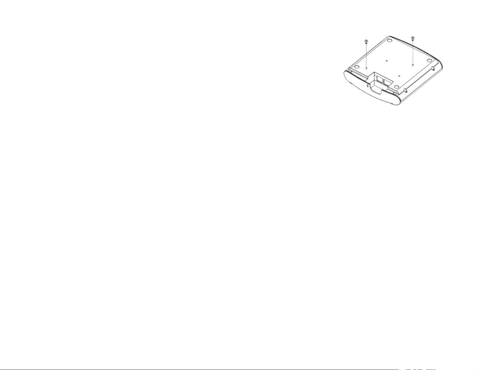
FIGURE 2 Attaching the shoulder scre
2. Insert two locking tabs (D in Figure 1) into the two
channels on Q410 Brack
Figure 3. The two tabs should line up with position 2.
FIGURE 3 Align the arrow on the tab with the position
printed depending on the AP being linked
et (C in Figure 1) as shown in
ws (B)
Package Contents
A complete Q410 eld installation package includes all of
the items listed below (see Figure 1 for illustrations):
• Q410 (A)
• M3 Shoulder Screw (B)
• Q410 Bracket (C)
• Locking Tab (D)
• R510 Band (E)
• R610 Band (F)
• R720 Band (G)
• M3 Flat Head Screw (H)
• Unit Removal Pin (J)
• Drywall Anchors (K)
• No 8. screws (L)
• Ethernet CAT 5 RJ-45 cable
• Service Level Agreement/Limited Warranty Statement
• Regulatory Statement
• This Quick Setup Guide
Copyright © 2018 ARRIS Enterprises LLC. All rights r
Published November 2018, Part Number 800-71629-001 Rev C
eserved. Page 1 of 4
Mounting Instructions
Q410 can be mounted to a ceiling tile T-bar, to a at
surface, to a pole using cable ties, or to a Junction bo
Mounting Q410 AP to a T-bar
Perform the following steps to mount Q410 to a ceiling
tile T-bar.
1. Attach the two shoulder screws (B in Figure 1)
provided using a 2 mm hex wrench or bit to Q410 (A
in Figure 1). It is recommended to tighten the screws
to 7 in-lbs (see Figure 2).
x.
3. Position the larger hole of the keyhole on Q410
et through shoulder screws on Q410, then slide
brack
the bracket away from the Ethernet ports until the
screws are in narrow parts of the keyholes (see Figure
4). Q410 locks in place on the bracket.
Page 2
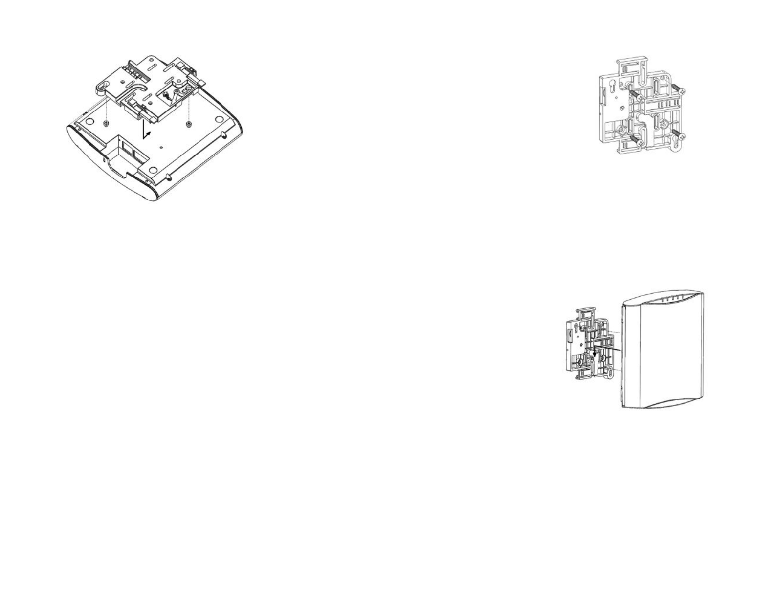
FIGURE 4 Attaching the brack
et to Q410
4. Clip Q410 and bracket assembly onto the T-bar. Slide
the last locking tab in so that it locks in place around
-bar into position 2 (see Figure 5).
the T
(see Figure 6). It is recommended to tighten the
scr
ws to 7 in-lbs.
e
4. Clip Q410, band, and bracket assembly onto the Tbar. Slide the locking tab so that it locks in place
around the T-bar in position 1 for the R610 and R720
or position 2 for the R510 (see Figure 5).
5. Install R510, R610, or R720 to the T-bar as per their
respective installation instructions.
6. Slide Q410 and the other unit together until the band
contacts the face on both sides (see Figure 6).
FIGURE 6 Aligning Q410 to other APs
FIGURE 7 Mounting the br
et to a surface
ack
5. Attach the two shoulder screws (B in Figure 1)
vided using a 2 mm hex wrench or bit to Q410 (A
pro
in Figure 1) as shown in Figure 2. It is recommended
to tighten the screws to 7 in-lbs.
6. Line up the screws with keyholes and slide Q410
away from the LED Indicators. Q410 locks in place on
the bracket (see Figure 8)
FIGURE 5 Attaching the bracket to the T-bar
Aligning Q410 to R510, R610, or R720
Perform the following steps to align Q410 to R510, R610,
or R720.
1.
Attach two tabs as shown in Figure 3. The two tabs
should lock in position 1 for R610 and R720 or
position 2 for R510.
2. Attach the bracket to Q410 (see Figure 4).
3. Attach the corresponding band (E, F, or G in Figure 1)
to Q410 using two M3 at head screws (H in Figure 1)
Mounting Q410 to a Flat Surface
Perform the following steps to mount Q410 to a at
surface.
If you are mounting Q410 on a at surface, then you
1.
will also need an electric drill with a 4.75 mm (3/16")
drill bit, and the four No. 8 zinc plated drywall screws
(L in Figure 1) and plastic wall anchors (K in Figure 1)
included with the kit.
2. Remove the three tabs (D in Figure 1) and set them
aside or store them in the original box.
3. Use the secure mounting bracket as a template to
mark the locations for four drill holes on the
mounting surface. There are four screw holes
available on the secure mounting bracket.
4. Line up the bracket and attach to surface with the
drywall screws provided. Make sure the bracket is
oriented as shown in Figure 7.
FIGURE 8 Attaching Q410 to the Bracket
Mounting Q410 to a Pole using Cable Ties
Perform the following steps to mount Q410 to a Pole
using Cable Ties.
If you are mounting Q410 on a pipe or pole, then feed
two customer-provided cable ties through the slots
on the secure mounting bracket (see Figure 9).
Copyright © 2018 ARRIS Enterprises LLC. All rights r
Published November 2018, Part Number 800-71629-001 Rev C
eserved. Page 2 of 4
Page 3

FIGURE 9 Mounting slots for mounting the brack
pole or pipe
et to a
Mounting Q410 to a Junction Box
Perform the following steps to mount Q410 to a Junction
x.
Bo
1. If you are mounting to a junction box, insert two
customer-provided screws through the slots (see
Figure 10) and secure the bracket to the junction box.
FIGURE 10 Attaching the bracket to a junction box
2. Attach Q410 as shown in Figure 8.
Removing Br
Perform the following steps to remove bracket from a TBar.
1. Move the ceiling tiles out of the way.
2. Lift the lever arm of the locking tab and slide the tab
away from the T-bar to release Q410 bracket
assembly from the T-bar (refer Figure 11).
FIGURE 11 Removing the bracket from the T-bar
Q410 and bracket assembly comes away from the Tbar.
acket from a T-Bar
Removing Q410 from the Bracket
Perform the following step to remove Q410 from the
bracket.
Insert the unit removal pin (J in Figure 1) into the hole
on the side of the bracket (see Figure 12) to unlock
the mounting bracket from Q410 enclosure, then
slide Q410 toward the LED Indicator lights and then
pull Q410 away until it detaches from the bracket.
FIGURE 12 Removing the br
acket from Q410
Making the Connections
Be sure to use a Cat 5e or better Ethernet cable with nonbooted connectors (see Figur
one end of the Ethernet cable to an 802.3at Type 2-
certied switch or PoE+ injector (sold separately). Attach
the other end of the Ethernet cable to the PoE+ IN port
on Q410 as shown in Figure 14. If using an AC/DC
adapter, connect it to the 48V DC power port in Figure 14
and to an electrical outlet.
If connecting to other APs, connect the enclosed short
Ethernet CAT 5 RJ-45 cable from the PoE+ OUT port of
Q410 to the PoE in port of the other AP.
NOTE: Alternative/Optional power sour
AC/DC adapter, can be ordered separately from
Ruckus. The details are as follows:
1. PoE+: P/N 902-0180-US00
(It includes KIT, SPARE, Integrated Power over
Ethernet (PoE) Injector (10/100/1000 Mbps), w/US
Power Cord, 1 Unit)
2. AC/DC adapter: P/N 902-1170-US00
(It includes KIT, SPARE, Modular AC/DC Power
adapter, 48V - 36W, w/US Power Cord, 1 Unit)
e 13). If using PoE+, attach
ces, PoE+ and
Copyright © 2018 ARRIS Enterprises LLC. All rights r
Published November 2018, Part Number 800-71629-001 Rev C
eserved. Page 3 of 4
Page 4

FIGURE 13 Non-booted Ethernet Connector
FIGURE 14 Port Locations
Checking the LED Lights
LED lights verify the installation of APs. Once connected,
the AP will power on and automatically connect to the
Ruckus Cloud o
see some activity and after 5-10 minutes all lights should
turn solid Green or solid Amber (LTE LED).
If any light is o or ashing, see the following table to
help you troubleshoot an issue:
ver the Internet to congure itself. You will
For More Information
The AP is now operational and can be further managed
by the Ruckus Cloud service. For more information, refer
to the appropriate Ruckus Wireless Cloud documentation
or visit http://support.ruckuswireless.com
©
2018 ARRIS Enterprises LLC. All rights reserved.
ARRIS, the ARRIS logo, Ruckus, Ruckus Wireless, the Ruckus logo, and
the Big Dog design are trademarks of ARRIS International plc and/or
its aliates. All other trademarks are the property of their respective
owners.
Light Troubleshooting Action
PWR Check Power, Ethernet connections and PoE
(802.3at Type-2 (PoE+) Certied) switch.
EMS
EPC Check Internet connection and network/
SYNC Ensure at least one AP in the network is
LTE For additional guidance, use the Ruckus
Copyright © 2018 ARRIS Enterprises LLC. All rights r
Published November 2018, Part Number 800-71629-001 Rev C
Check Internet connection and network/
rewall settings.
rewall settings.
near an unobstructed window for a good
GPS signal.
cloud or contact Customer Care.
eserved. Page 4 of 4
Page 5

Page 1
800-72098-001-A1
Q410 – LTE Access Point Ruckus Wireless Inc., an ARRIS Company
Federal Communications Commission Notices
This product complies with Part 15 of the FCC Rules. Operation is subject to the following two conditions: (1) this device may not cause harmful
interference, and (2) this device must accept any interference received, including interference that may cause undesired operation.
Warning: Changes or modifications to this equipment that have not been approved by Ruckus Wireless may void the user's authority to operate this
equipment.
For Class B Equipment:
Note: This equipment has been tested and found to comply with the limits for a Class B digital device, pursuant to part 15 of the FCC Rules. These
limits are designed to provide reasonable protection against harmful interference in a residential installation. This equipment generates uses and can
radiate radio frequency energy and, if not installed and used in accordance with the instructions, may cause harmful interference to radio
communications. However, there is no guarantee that interference will not occur in a particular installation. If this equipment does cause harmful
interference to radio or television reception, which can be determined by turning the equipment off and on, the user is encouraged to try to correct the
interference by one or more of the following measures:
— Reorient or relocate the receiving antenna. — Increase the separation between the equipment and receiver.
— Connect the equipment into an outlet on a circuit different — Consult the dealer or an experienced radio/TV technician for help.
from that to which the receiver is connected.
This device meets all requirements specified in the FCC Part 96 Rules. This transmitter must not be co-located or operate in conjunction with any other
antenna or transmitter.
Radiation Exposure Statement:
This equipment complies with FCC radiation exposure limits set forth for an uncontrolled environment. This equipment should be installed and operated
with minimum distance 25 cm between the radiator & your body.
Safety Notices and National Restrictions
This product is intended to be installed at a restricted access location and is marked with a visible warning that the surface may be hot
Professionally Installed Products
The product is to be installed according to the installation instructions. The User/Operator does not have access to the device once the device is
installed and in use. Provisions for permanent grounding are provided.
1. Installation personnel: This product is designed for a specific application and is to be installed by qualified personnel with knowledge of RF and
applicable rules. General users are not to attempt installation or changing settings.
2. Installation location: The product is to be installed at a location where the radiating antenna can be kept at least 25 cm from any nearby persons in
normal operation conditions to meet regulatory RF exposure requirement.
3. Installation procedure: Please refer to installation instructions for details.
4. Warning: Please carefully select the installation position and make sure that the final output power does not exceed the limit set forth in US CFR 47
Part 96. Violation of the rule could lead to serious federal penalty.
Products intended to be powered by an external power supply:
Warning –This product is intended to be supplied by a Listed Direct Plug-In Power Unit marked Class 2 or LPS (sub-clause 2.5 of standard EN 60950-
1). Available Ruckus power supplies intended for product operation are identified in the product datasheet. The last two digits of the power supply
part number represent the country code. For additional applicable power supplies/options, see user instructions and product datasheet.
Medical Statement
Ruckus Wireless Access Points shall only be used in ME systems where the intended EM ENVIRONMENT does NOT rely on the Wireless radio link for
BASIC SAFETY or ESSENTIAL PERFORMANCE of the ME SYSTEM.
Ruckus Wireless, Inc. 350 West Java Drive Sunnyvale, CA 94089 USA
 Loading...