

Page 1
S2
USER MANUAL
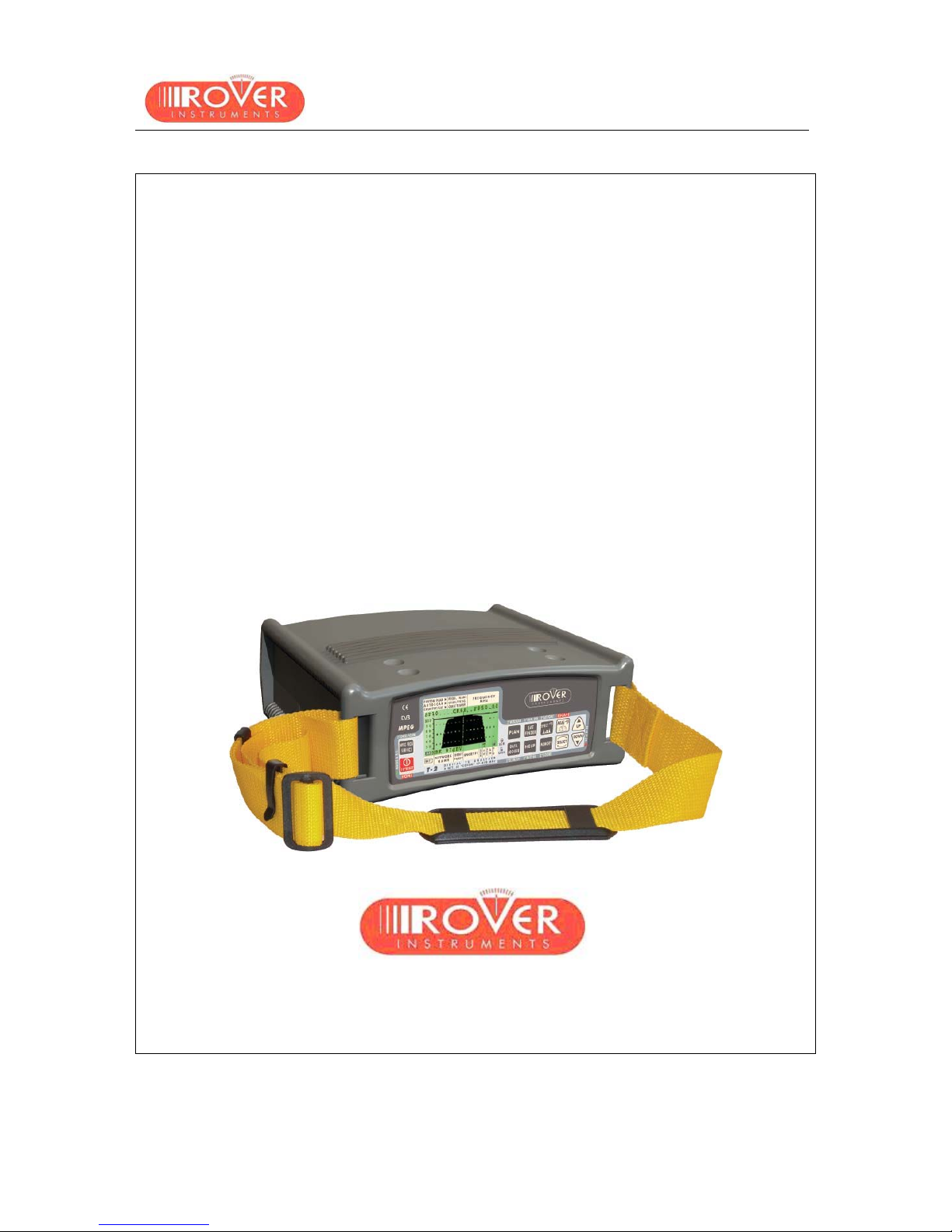
S2 SCOUT
USER MA N UAL
Analogue and Digital Satellite Analyzer
930 - 2150 MHz QPSK
ROVER LABORATORIES S.p.A.
Via Parini 2 – 25019 Sirmione (BS) – ITALY
www.roverinstruments.com
Page 2

S2
USER MANUAL
2
MANUAL CODE
UG-S2-1.25-BS1.0-EN-1.0
RELEASE DATE
JUNE 2007
We all wish to sincerely thank you for choosing our measurement instrument, which is
currently approved and everyday used by the major Service Providers, Broadcasters
and by really many users all over in the world.
Like to them all, this measurement instru ment will provide you with easiness of use and a full
range of measuremen t capabilities.
Our everyday efforts are targeted to continuously develop state of the art instruments,
capable to fulfil and possibly to exceed your expectations and all of your needs.
We are able to research and develop further improvements day after day
also thanks to your valuable suggestions and contributions.
Please let us know about your opinion, suggestions, and special requests
through our dedicated email address:
wecare@roverinstruments.com
as well as by call i ng our Technical Supp ort:
ROVER Hotline: +39 030 9198299
We are positive your expectations and your needs will be fully satisfied.
We are positive you will be happy with us.
Thank - you again .
Edoardo Romano
Chairman
Page 3

S2
USER MANUAL
3
INDEX
OVERVIEW........................................................................................................................... 5
1 __ FRONT PANEL AND KEYBOARD..........................................................................................5
2 __ SIDE PANELS........................................................................................................................6
USER MANUAL.................................................................................................................... 7
3 __ TURN THE METER ON..........................................................................................................7
4 __ TURN THE METER OFF........................................................................................................7
5 __ CHECK THE BATTERY CHARGE STATUS............................................................................7
6 __ METER SETUP: MPEG PROG SERVICE ...............................................................................8
6.1 MAIN SETUP ................................................................................................................8
~ ___ AUTO METER OFF (TIMER O FF).............................................................................8
~ ___ FIELD LEVEL MEASUREMENT UNIT (UNIT)............................................................8
~ ___ LANGUAGE...............................................................................................................9
~ ___ KEYS BEEP ..............................................................................................................9
~ ___ DISPLAY BA C KL IGHT (DISP.L IGHT)........................................................................9
6.2 METER SETUP............................................................................................................9
~ ___ SET THE LOCA L OSC IL L ATOR FRQUE N C Y............................................................9
~ ___ SET THE AVAILABLE NUMBER OF POLARIZATIONS FOR THE LNB 1..................9
~ ___ SET THE AVAILABLE NUMBER OF POLARIZATIONS FOR THE LNB 2................10
~ ___ MANAGING LNB OR MULTISWITCH SUPPORTI NG THE SCR COMMUNICATIO N
PROTOCOL: SAT SCR MENU................................................................................ 10
{ SatSCR USER:....................................................................................................................10
{ SatSCR FREQ:....................................................................................................................10
7 __ DC AT RF IN.........................................................................................................................11
8 __ SATELLITE DISH ALIGNMENT............................................................................................12
8.1 DISH ALIGNMENT TO A SPECIFIC SATELLITE WITH AUTOMATIC SATELLITE
IDENTIFICATION (SAT FINDER)................................................................................12
8.2 “DUAL FEED” DISH ALIGNMENT...............................................................................13
~ ___ PREPARING TO ALI GNE MENT: SWITCH DiSEqC.................................................13
~ ___ DISH ALIGNMENT AND MEASUREMENTS............................................................13
{ LNB1 SATELLITE SETUP....................................................................................................14
{ LNB2 SATELLITE SETUP....................................................................................................14
{ DISH ALIGNMENT AND FINE ALIGNMENT.........................................................................14
8.3 POINTING AND/OR MOVING A MOTOR CONTROLLED DISH (DISEqC MOTOR)....14
~ ___ MOVE......................................................................................................................15
~ ___ STORE....................................................................................................................15
~ ___ GOTO......................................................................................................................16
~ ___ RESET ....................................................................................................................16
8.4 ANTENNA POINTING AI D TON E: BUZZER................................................................16
9 __ SIGNAL TUNING: PLAN.......................................................................................................17
9.1 EXPLORING ALL THE SATELLITE TRANSPONDERS...............................................17
~ ___ CHANGING THE SATELLITE ..................................................................................17
~ ___ CHANGE TH E TR A N SPONDER..............................................................................18
~ ___ MANUALL Y CHA N G E TH E FR E QUENCY...............................................................18
Page 4

S2
USER MANUAL
4
9.2 MANUALLY TUNING THE TRANSPONDE R (BY KNOWING A LL THE DISTINCTIVE
PARAMETERS)..........................................................................................................18
9.3 NAVIGATE THE SOLE TRASPONDERS INCLUDED IN A USE R DEFINED MEMORY
PLAN..........................................................................................................................20
~ ___ SELECT THE DESIRED TRANSPONDER...............................................................20
~ ___ MANUALL Y MOD IFY THE FREQU E N C Y V AL U E....................................................21
~ ___ MODIFY THE TRANSPONDER MEMORY PLAN TO BE NAVIGATED ....................21
10 _ PERFORMING MEASURES: MEAS.....................................................................................22
10.1 ANALOGUE TRANSPONDER.................................................................................... 22
~ ___ LEVEL MEASUREMENT.........................................................................................22
~ ___ SPECTRUM ANALYSIS...........................................................................................22
10.2 DIGITAL TRANSPONDER..........................................................................................23
~ ___ THE TRANSPONDER TUNED IS INCLUDED IN A PRE-MEMORIZED SATELLITE
OR THE TRANSPONDER WAS MANUALLY TUNED..............................................23
~ ___ THE TRANSPONDER IS INCLUDED IN A USER-DEF I N ED TRANSP ONDER
MEMORY PLAN......................................................................................................24
{ CHANNEL POWER MEASUREMENT.................................................................................. 24
{ NOISE MARGIN, QUALITY TEST, MER E EVM MEASUREMENTS..................................... 24
{ BER MEASUREMENTS BEFORE AND AFTER VITERBI CORRECTION .............................25
{ FEC AND BOUQUET MAIN DATA....................................................................................... 25
{ SERVICE LIST OF THE CURRENT BOUQUET ................................................................... 26
{ SPECTRUM ANALYSIS....................................................................................................... 26
11 _ SPECTRUM ANALYZER MODE...........................................................................................27
11.1 CHANGE TH E TR AN S PONDER.................................................................................27
11.2 CHANGE TH E MA R KE R POSITION (FR E QU EN C Y)..................................................27
11.3 EDITING THE SIGNAL LEVEL END OF SCALE......................................................... 28
11.4 CHANGE SPAN..........................................................................................................28
11.5 ACTIVATE THE MAX HOLD FUNCTION....................................................................28
12 _ AUTOMATIC STORAGE OF TRANSPONDERS MEASURES (DATA LOGGER)................... 29
12.1 AUTOMATICALLY STORE TRANSPONDER MEASURES (AUTO MEAS&STORE)...29
12.2 DELETE A MEMORY PLAN........................................................................................30
13 _ CREATING A USER DEFINED TRANSPONDER MEMORY PLAN.......................................31
13.1 MANUALLY CREATE A USER DEFINED MEMORY PLAN: MEMORY.......................31
~ ___ CREATE A BRAND NEW MEMORY PLAN..............................................................31
~ ___ ADD A NEW TRAN S PONDER TO AN E XISTING MEM OR Y PLA N.........................32
13.2 ADD A SELECTED TRASPONDER TO A EXISTING USER DEFINED MEMORY PLAN
32
13.3 DELETE A USER DEFINED MEMORY PLAN.............................................................33
~ ___ DELETE A USER DEFINED MEMORY PLAN..........................................................33
~ ___ DELETE A LOGGER FILE (LOGGER MEMORY PLAN)..........................................33
14 _ TECHNICAL SPECIFICATIONS........................................................................................... 35
SERVICE NOTES AND GUARANTEE REGULATIONS (UE AND EXTRA UE)................. 37
FAULT IDENTIFICATION FORM ........................................................................................ 39
MANTAINING THE METER................................................................................................ 40
DISPOSAL OF ELECTRONIC EQUIPMENT
..................................................................... 41
Page 5
S2
USER MANUAL
5
OVERVIEW
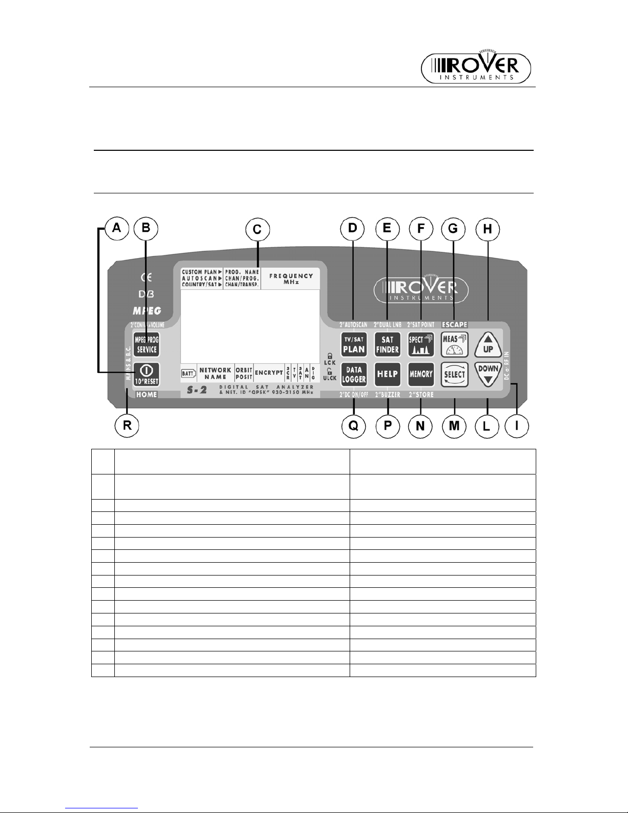
1 FRONT PA NEL AND KEYBOARD
Main Function Secondary Function
(press and hold for 2”)
A Met er ON/OFF Lev. And CH. Power Meas . (press 2”)
RESET (press and hold 10”)
B MPEG SERVICE LIST Enable configuration menu
C LCD (Dot matrix) Displa y
D PLAN AUTOSCAN
E SAT FINDER DUAL LNB
F SPECT SAT POINT
G MEAS
H UP (also “Ente r” k ey)
I LED DC at RF IN
L DOWN (also “Enter” key)
M SELECT
N MEMORY STORE
P HELP BUZZER
Q DATA LOGGER DC ON/OFF
R LED external power source ON
Page 6
S2
USER MANUAL
6
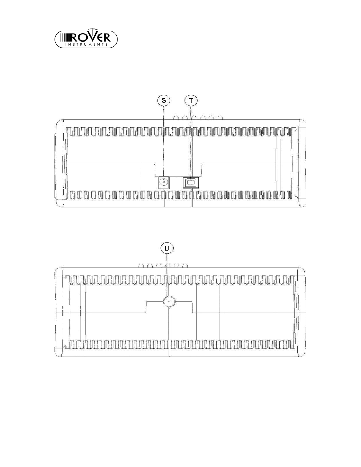
2 SIDE PANELS
[S] External Power Source ~ 12 Vac
[T] USB socket
[U] RF inlet (75 Ω, type “F” connec tor)
Page 7
S2
USER MANUAL
7
USER MANUAL
3 TURN THE METER ON
Press and release the [A] key.
4 TURN THE METER OFF
Press and hol d for 2” t he [A] key.
5 CHECK THE BATTERY CHARGE STATUS
When the meter is on, at the bottom left corner of the LCD disp lay [B] an icon will show
the current power source of the meter: built-in battery or mains external feed.
Build-in battery feed Mains external feed
Connect the supplied AC adaptor or the supplied cigarette lighter adaptor to the socket
[S] (located on the left side of the meter) to recharge the built-in battery. When the
meter is connected to an external power supply, the LED indicator [R] (located on the
meter front panel) turns on.
Page 8
S2
USER MANUAL
8
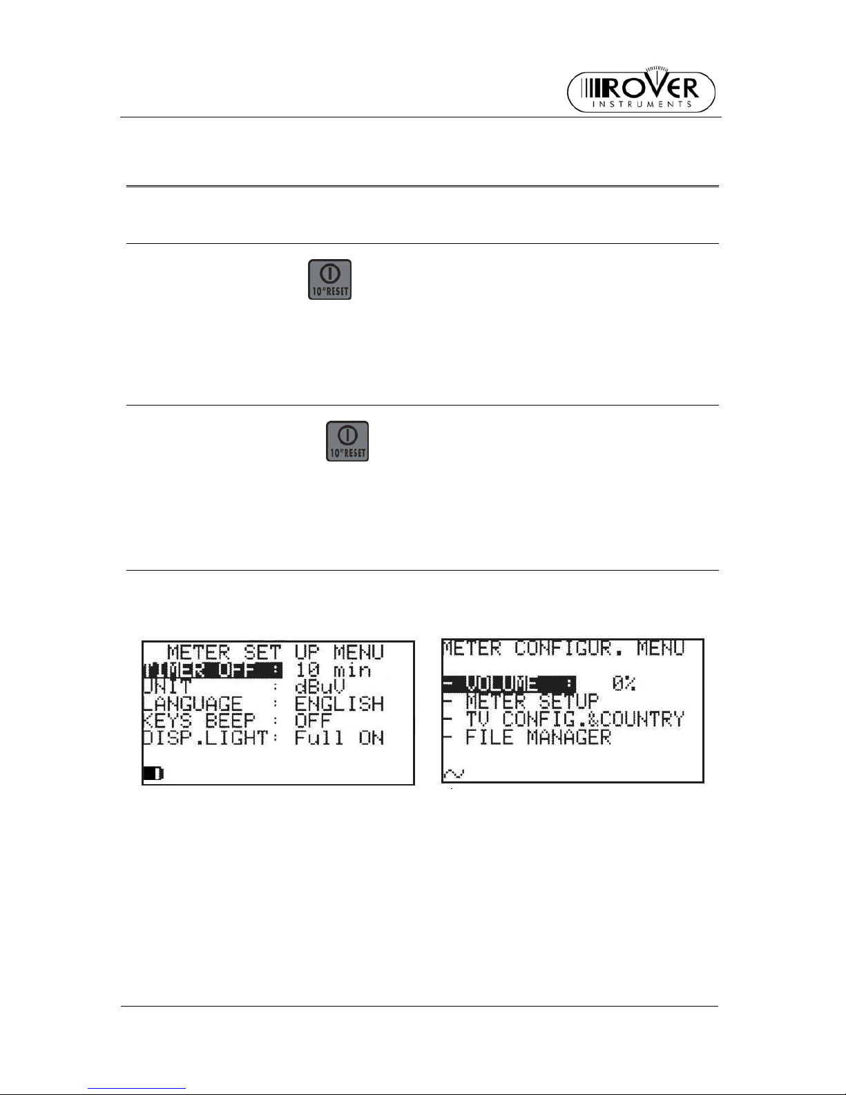
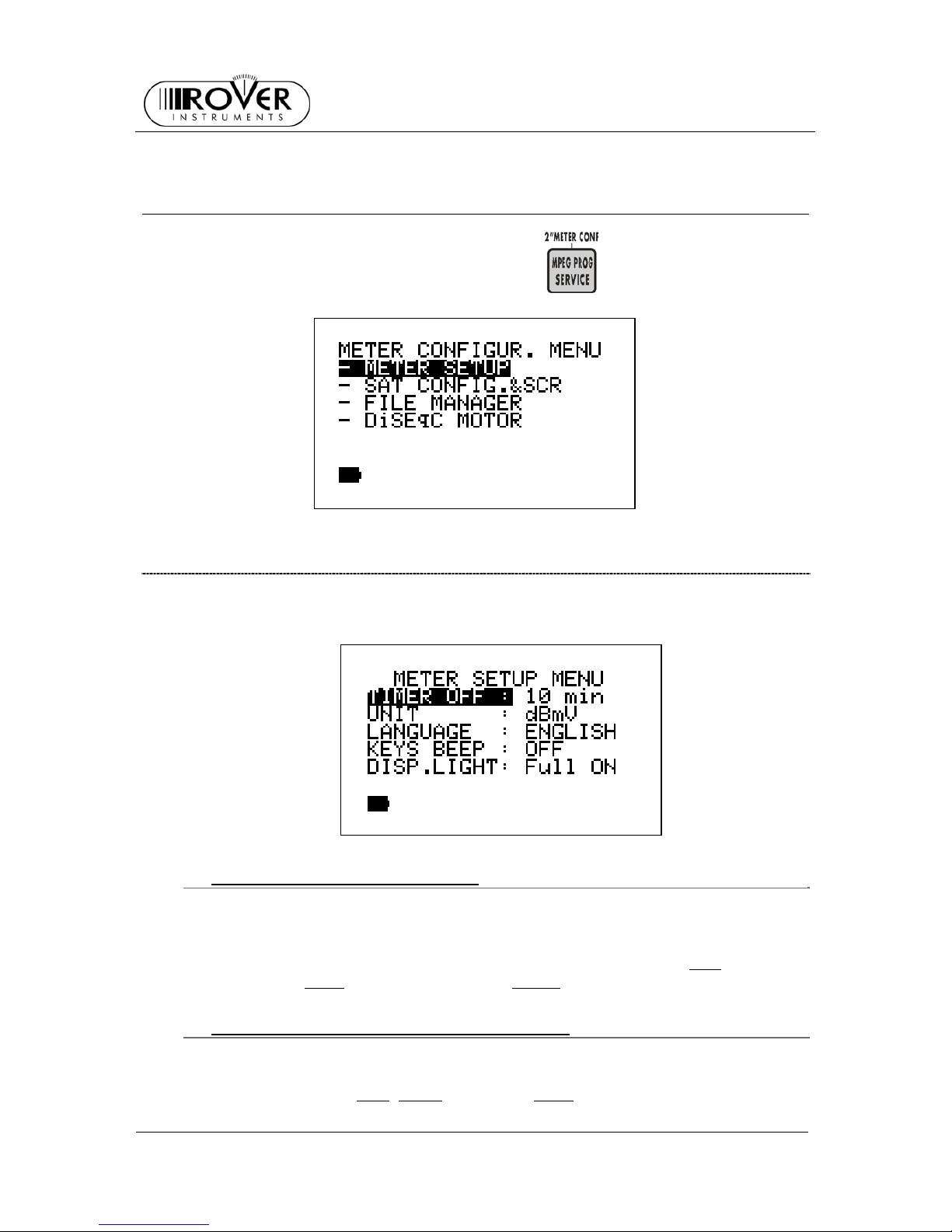
6 METER SETUP: MPEG PROG SERVICE
Press and hold for 2” the MPEG PROG SERVICE [B] key.
6.1 MAIN SETUP
Press repeatedly the SELECT [M] key to highlight the label METER SETUP.
Press the UP[H] key to access the main set up menu
~ AUTO METER OFF (TIMER OFF)
If no key is pressed, the meter will au tomatically turn off after a certain time-de lay.
To set the auto meter off delay:
Press repeatedly the SELECT [M] key to highlight the label TIMER OFF
Press repeatedly either the UP [H] or the DOWN [L] key to select: OFF
(meter
always on), 5 min
(meter off after 5 min), 10 min (meter off aft er 10 min)
~ FIELD LEVEL MEASUREMENT UNIT (UNIT)
Press repeatedly the SELECT [M] key to highlight the label UNIT
Press repeatedly either the UP [H] or the DOWN [L] key to set the desired
measurem e nt uni t: dBm
, dBmV (dBmillivolt) dBuV (dBmicrovolt)
Page 9
S2
USER MANUAL
9
~ LANGUAGE
Press repeatedly the SELECT [M] key to highlight the label LANGUAGE
Press repeatedly the UP [H] or DOWN [L] keys to set the desired langauge. In
some release only the english language is available.
~ KEYS BEEP
Press repeatedly the SELECT [M] key to highlight the label KEYS BEEP
Press repeatedly the UP [H] o DOWN [L] key to set the desired volume: OFF
,
LOW
, MEDIUM or HIGH.
~ DISPLAY BACKLIGHT (DISP.LIGHT)
When no key is pressed, the display backlight will turn off after a certain timedelay. To set the proper time:
Press repeatedly the SELECT [M] key to highlight the label DISP.LIGHT
Press repeatedly either the UP [H] or the DOWN [L] key to select FullON
(light
always on) or 30 sec
(light off after 30 sec)
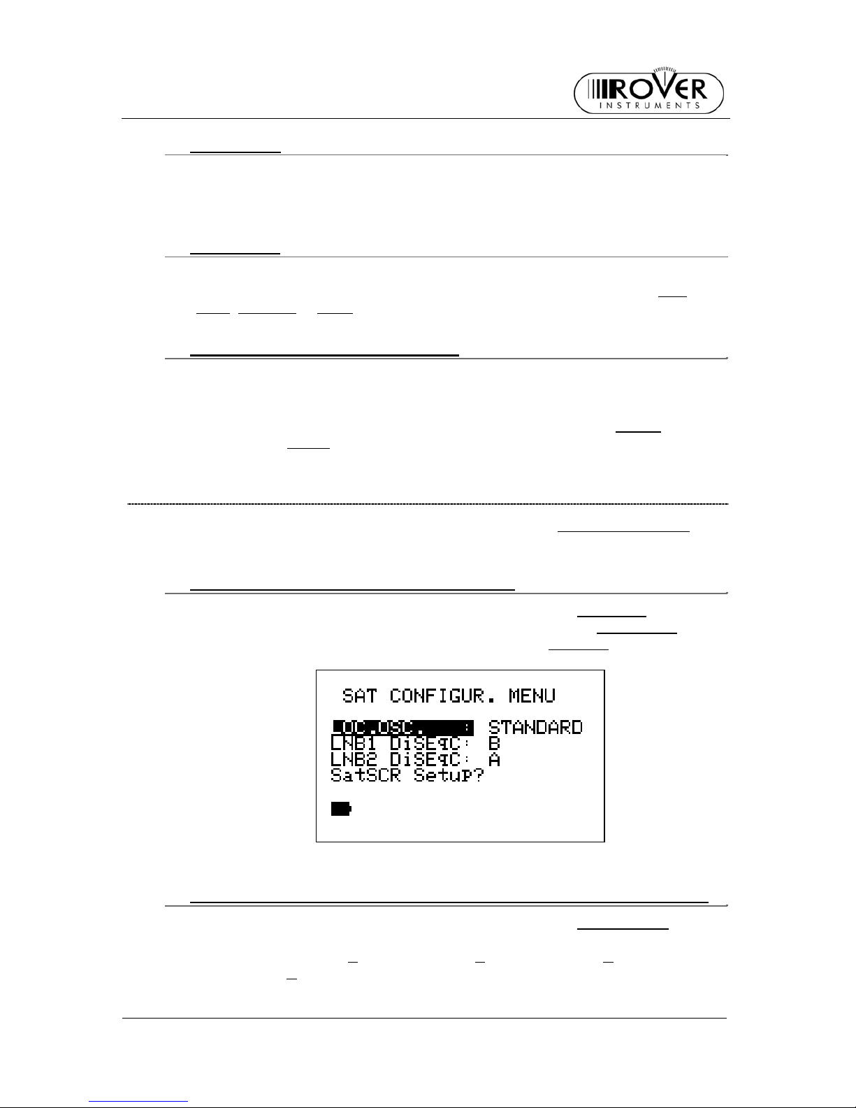
6.2 METER SETUP
Press repeatedly the SELECT [M] key to highlight the label SAT CONFIG.&SCR
Press the UP [H] key to access the configuration menu.
~ SET THE LOCAL OSCILLATOR FRQUENCY
Press repeatedly the SELECT [M] key to highlight the label LOC.OSC.
Press repeatedly either the UP [H] or the DOWN [L] key to set STANDARD
(signal
direct from the antenna, req uir i ng down-conver si o n) or 0MHz(IF)
(signal with
interme diate frequency , e.g. coming from a LN B)
~ SET THE AVAILABLE NUMBER OF POLARIZATIONS FOR THE LNB 1
Press repeatedly the SELECT [M] key to highlight the label LNB1 DiSEqC.
Press repeadetly the UP [H] or DOWN [L] key to set the required number of
polarizations for LNB1 (A
= 4 polarizati o ns, B = 8 polarizations, C = 12
polarizations, D
= 16 polari zati o ns ) .
Page 10
S2
USER MANUAL
10
~ SET THE AVAILABLE NUMBER OF POLARIZATIONS FOR THE LNB 2
Press repeatedly the SELECT [M] key to highlight the label LNB2 DiSEqC.
Press repeadetly the UP [H] or DOWN [L] key to set the required number of
polarizations for LNB1 (A
= 4 polarizati o ns, B = 8 polarizations, C = 12
polarizations, D
= 16 polari zati o ns ) .
~ MANAGING LNB OR MULTISWITCH SUPPORTING THE SCR
COMMUNICATION PROTOCOL: SAT SCR MENU
This function is used when controlling or checking single cable satellite
installations.
Press repeatedly the SELECT [M] key to highlight the label SatSCR Setup?
. Press
the UP [H] key to access this function.
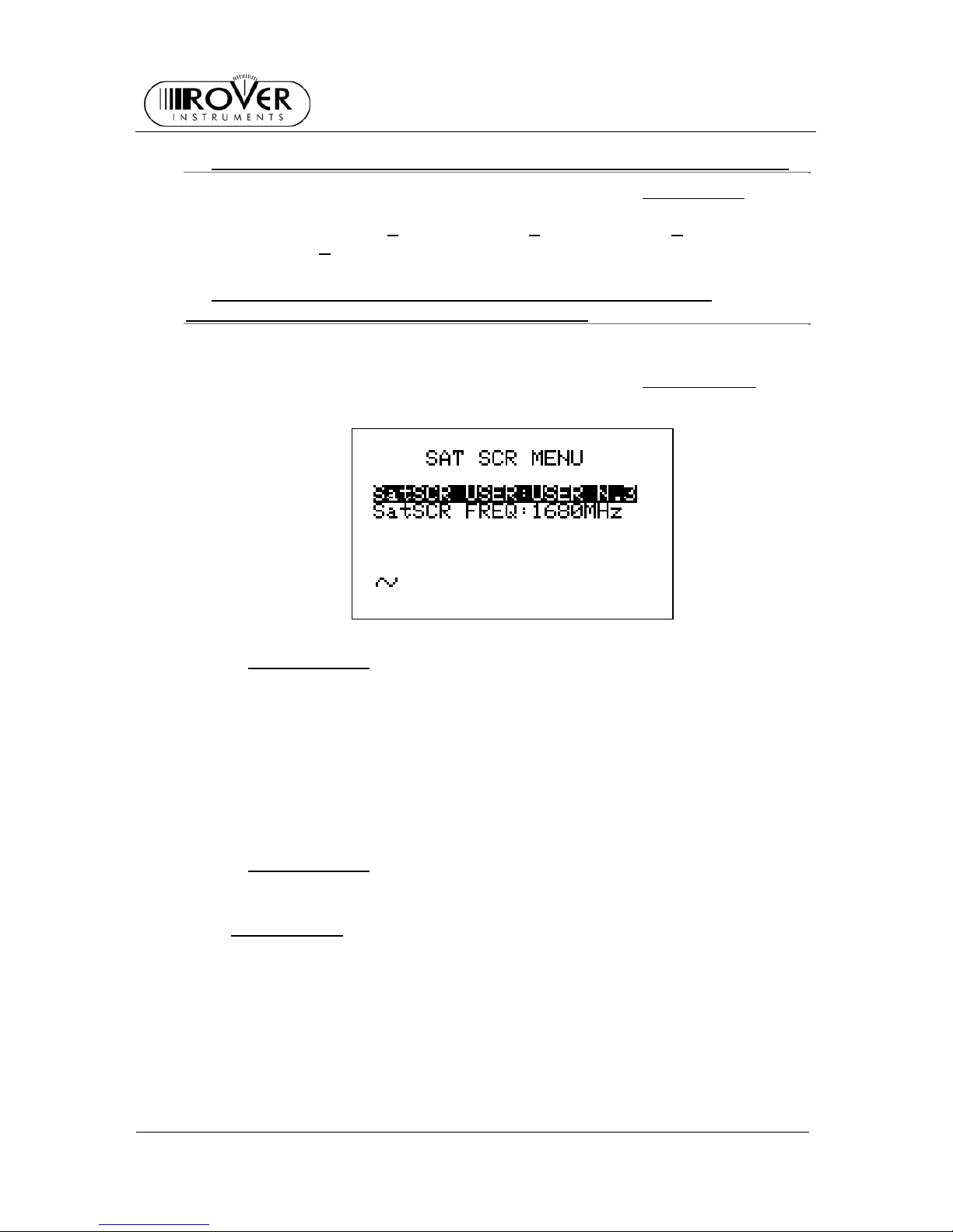
{ SatSCR USER:
Pres s the SELECT [M] key to highlight the label Sa tSCR USE R. Press
repeatedl y the UP [H] o DOWN [L] to set the user identification num ber . Th e
measurement in progress will be referred to this user.
It is possible to identify up to 8 different user, each with a particular SCR
frequency.
To manually set each user frequency, please refer to next item SatSCR FREQ:
at page 10. If the label NONE appears in the field of the selected user, it is not
possible to manually set any frequency.
{ SatSCR FREQ:
To manually set the SCR frequency for a given user, select the desired user
identification number and then press the SELECT [M] key to highlight the label
SatSCR FREQ:
. Press repeatedly either the UP [H] or the DOWN [L] key to set
the desired frequency in 1 MHz step . If the label NONE appears in the field of
the selected user, it is not possible to manually set any frequency.
Page 11
S2
USER MANUAL
11
7 DC AT RF IN
To turn the DC at RF in function on, press and hold for 2” the DATA LOGGER
[Q] key.
When the function is on, the yellow led DC at RF in [I] will turn on too.
WARNING: BEFORE TURNING THE DC AT RF IN FUNCTION ON, PLEASE
CAREFULLY CHECK WHETER THE SYSTEM WHICH THE METER IS
CONNECTED TO, IS SUITABLE FOR THE DC AT RF IN.
To turn the DC at RF in function off, Per disattivare la telealimentazione, press and
hold for 2” the DATA LOGGER key. When the function is off, the yellow led DC at RF
in [I] will turn off.
Page 12
S2
USER MANUAL
12
8 SATELLITE DISH ALIGNMENT
8.1 DISH ALIGNMENT TO A SPECIFIC SATELLITE WITH
AUTOMATIC SATELLITE IDENTIFICATION (SAT FINDER)
The meter can assist you in aligning the satellite dish to a specific satellite. Just
mount and briefly align the dish to the desired sa tellite. The meter can detect if you
are really point ing to the desired satellite by looking for (maximum) three user-defined
reference transponders within any received satellite signal, then it can support you in
fine-aligning the dish.
To roughly align the dish to a specified satellite, proceed as follo ws:
Select either the des ired satellite (refer to chapter 9 SIGNAL TUNING: PL AN at page
17, and, in detail, to item 9.1 EXPLORING ALL THE SATELLITE TRANSPONDERS
at page 17) or the Trasponder Group where one or more trasponder carried by the
required satellite are included (refer to chapter 9 SIGNAL TUNING: PLAN at page 17,
and, in detail, to item9.3 NAVIGATE THE SOLE TRASPONDERS INCLUDED IN A
USER DEFINED MEMORY PLAN at page 20).
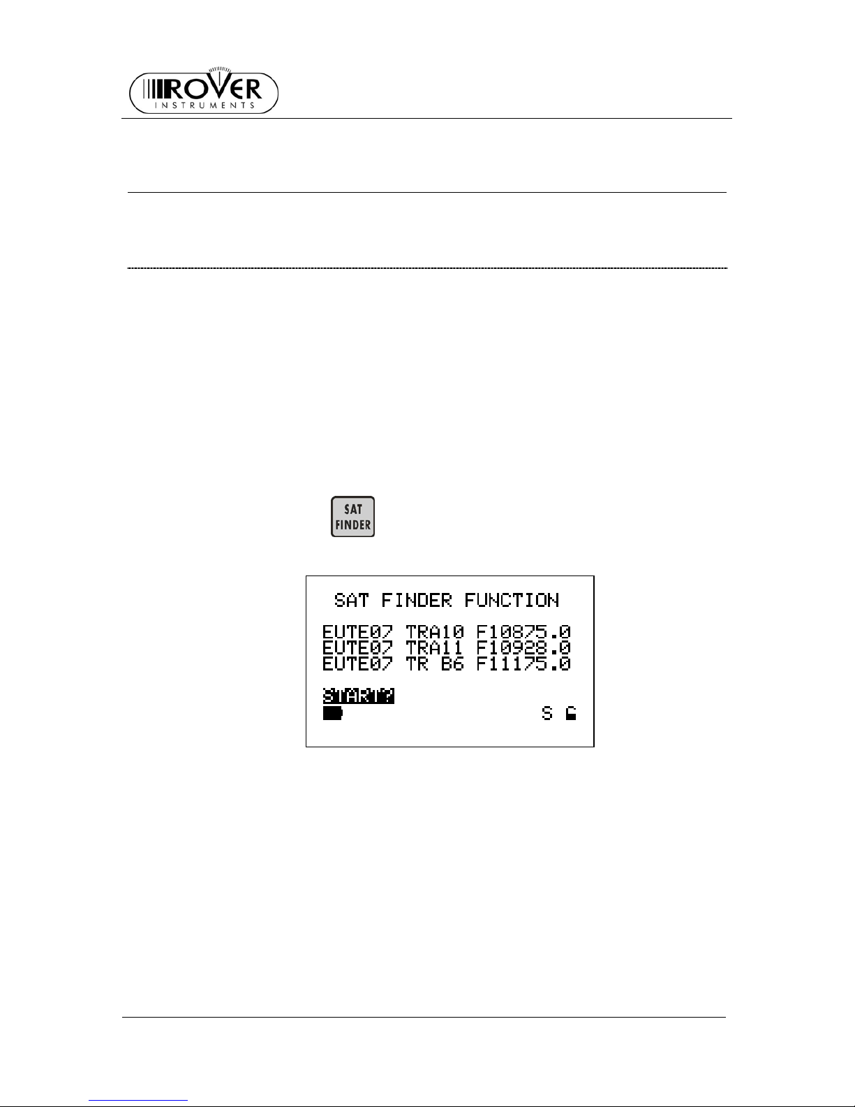
Press the SAT FINDER
[E] key to show the following screen (in this case, the
reference is EUTELSAT 7° satellit e):
If the displayed transponders do not match with the appropriate ones, press
repeadetly the SELECT [M] key to highlight the transponder name to be modified,
and then select the required transponder by pressing either the UP [H] or the DOWN
[L] key.
In case you wish to indicate less than three reference transponders, just set up the
one or the two reference ones you like, and set into the unused field(s) the reference
transponder set up as the first one.
After setting the appropriate trasponder(s), press the SELECT [M] key to highlight
the item START? and press UP [H] key to activate the SAT FINDER function
(automatic satellite identification).
During the identification process, the START icon will be replaced by the item
SATLOOKING and a rotating bar will be disp layed as an “in progress” indicator.
Page 13
S2
USER MANUAL
13
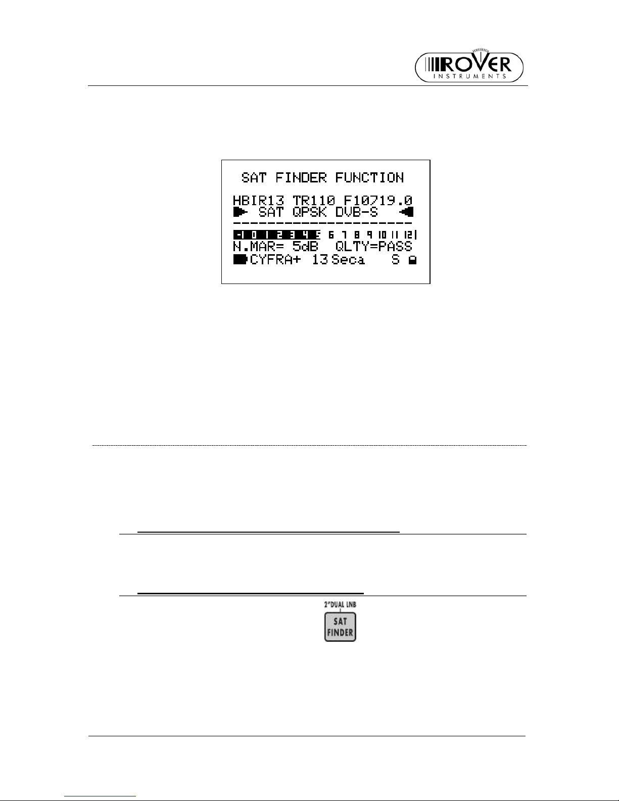
When the sa te llite is correctly found, the meter will start the buzzer (chec k item 8.4
ANTENNA POINTING AID TONE: BUZZER at page 16). The Noise Margin value
(also displayed on a level bar with peak level) and the Quality Test results will be
disp layed on the screen:
With the help of the buzzer sound and maximizing the lenght of the bar, proceed to
fine alig n the dis h .
To fine align the dis h on the tw o polarizatio ns (“c r oss - pol” ) , pr es s a nd r el ease the
MEAS [G] key. The transponder currently under measurement will be highlighted (“A”
polarization). Using the UP [H] and DOWN [L] keys, select a transponder with a
different polarization (“B” polarization) and just repeat the dish fine alignment on this
last transponder.
To confirm the alignment, just check that a trasponder with “A” polarization is
correctly received.
8.2 “DUAL FEED” DISH ALIGNMENT
This meter allows the alignment of Dual LNB satellite dishes by performing
simultaneous measurements on both LNB, with no need to continuously switch
between RF cables and to set different frequencies.
~ PREPARING TO ALIGNEMENT: SWITCH DiSEqC
Both cables from the two LNB must be connected to the meter via a DiSEqC
switch; this switch is provided with the meter.
~ DISH ALIGNMENT AND MEASUREMENTS
Press and hold for 2” the SAT FIND ER [E] key to show the following
screen:
Page 14
S2
USER MANUAL
14
{ LNB1 SATELLITE SETUP
The display will already highlight either the satellite (the name of the satellite will
be shown) or the Transponder Memory Plan (the word PLAN… will be shown) to
align the LNB1. Press either the UP [H] or the DOWN [L] key to select the
desired satellite or Transponder Memory Plan.
Then, press once the SELECT [M] key. The field representing the transponder
used to align the LNB1 will be highligh ted.
{ LNB2 SATELLITE SETUP
Press the SELECT [M] key to highlight either the satellite (the name of the
satellite will be shown) or the Transponder Memory Plan (the word PLAN… will
be shown) to align the LNB2. Press either the UP [H] or the DOWN [L] key to
select the desired satellite o r Tran sponder Memory Plan.
Then, press once the SELECT [M] key. The field representing the transponder
used to align the LNB1 will be highligh ted.
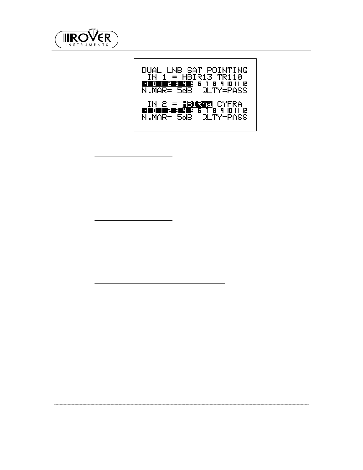
{ DISH ALIGNMENT AND FINE ALIGNMENT
When LNB1 and LNB2 have been selected, the display shows for each LNB the
Noise Margin and Quality Test (FAIL, MARGIN, PASS). The two level bars show
the actual Noise Margin value for each of the LNB, also with peak value memory.
The dish must be fine aligned up to obtain the minimum of the Noise Margin on
the two LNB at the same time.
To facilitate this alignment, each bar shows also the maximum value reached by
the Noise Margin of the matching LNB during this operation.
According to the signal receiving conditions, the Noise Margin might not be at its
maximum for both the LNB. In case, the satellite dish must be aligned to have
the best possible value – at the same time - for both the signals.
Press the MEAS [G] key to exit this function.
8.3 POINTING AND/OR MOVING A MOTOR CONTROLLED DISH
(DISEqC MOTO R )
Select either the satellite (please refer to chapt er 9 SIGNAL TUNING: PLAN and 9.1
EXPLORIN G ALL THE SATELLITE TRAN S PON DERS at page 17) or the re fer ence
Page 15

S2
USER MANUAL
15
transponder (please refer to chapter 9 SIGNAL TUNING: PLAN and 9.2 MANUALLY
TUNING THE TRANSPONDER (BY KNOWING ALL THE DISTINCTIVE
PARAMETERS) at oage 18) fo r the satellite to align the dish to.
• Press and hold for 2” the MPEG PROG SERVICE
[B] key.
• Press the SELECT [M] key to highlight DiSEqC MOTOR
• Press the UP [H] key to show the following screen:
The display third row f rom the top shows (left to right): the selected satellite na me (o r
the Transponder Memory Plan), the selected transponder and the relevant frequency
value.
The display bottom rows show (bottom to top, left to right): the name of the selected
bouquet, the encryption system in use, the Noise Margin value (also displayed on the
level bar with peak memory level), and the result of the Quality Test.
Also, the ACT.:
item is highlighted: this item indicates the command which will be
sent to the motorized antenna.
By pressing the UP [H] or DOWN [L] key, it is possible to select one of the 4 available
commands:
~ MOVE
This command moves the antenna to the direction mentioned in the DIR item
(EAST o WEST).
Press the SELECT [M] key to select the movement direction: highlight the item
DIR:
and then select the desired direction (EAST, WEST) by pressing the UP [H]
or DOWN [L] keys.
The measurement value s rep orted by the meter before the satellite or the
transponder identification (while the dish is moving) have to be neglected.
~ STORE
This command allows to store the current motor position. Up to 99 different
antenna positions can be stored in the meter (POS.: 1 to 99).
Press the SELECT [M] key to highlight the item POS.:
. and then select the
memory location where the current antenna position will be stored by pressing the
UP [H] or DOWN [L] keys.
Then press the SELECT [M] key to highlight the item STORE?
. and press the UP
[H] key to confirm.
Page 16

S2
USER MANUAL
16
~ GOTO
This command selects one of the 99 pre-stored antenna positions.
Pres s the SELECT [M] ke y to highli ght the item POS. :
and select the required prestored position by pressing the UP [H] or DOWN [L] keys.
Then, press the SELECT [M] key to highlight the item APPLY?
and fina lly press
the UP [H] key to send the command to the dish.
~ RESET
In case some no-go zones (banned sectors) were previously set up on the
concerned motor antenna system, this command removes any previously set
limitation.
Pres s the SELECT [M] ke y to highli ght the item APPLY?
, then press the UP [H] to
send the reset command.
8.4 ANTENNA POI NTING AID TONE: BUZZER
Press and hold for 2” the HELP [P] key.
You can hear a beep whose duty cycle is proportional to the signal Noise Margin.
This is a dish alignment aid feature: when the multiplex DVB is correctly found
(satellite is found) the meter will start the Buzzer and at the same time the screen will
display:
The screen second row shows (left to right) the selected Satellite or the selected
Transponder Memory Plan, the currently tuned transponder and the relevant
frequency value (on a reverse background). The frequency value can be modified by
pressing the UP [H] or DOWN [L] keys.
The two bottom rows show the Noise Margin measurement (also on a level bar with
peak memory function) and the Quality Test result.
Press any key to quit this function.
WARNING: THE BUZZER FUNCTION IS ACTIVE WITH DIGITAL SIGNALS ONLY
Page 17

S2
USER MANUAL
17
9 SIGNAL TUNING: PLAN
Connect the signal cable to the F connector [U] of the meter.
Press and release the PLAN
[D] key.
9.1 EXPLORIN G ALL THE SATEL LITE TRANSPONDERS
Press repeatedly the SELECT [M] key to highlight the label SATELLITE.
The name of required satellite should be highlighted. If not, select the required
satellite by pressing repeatedly either the UP [H] or DOWN [L] key.
Press the MEAS
[G] key.
The first row of the display will show the name of the selected satellite, the se lected
transponder and its frequency.
~ CHANGING THE SATELLITE
The satellite might be changed only from the PLAN SELECTION MENU screen. This
screen can be accessed by pressing and releasing the PLAN [D] key. Only prememorized satellite can be chosen.
Page 18

S2
USER MANUAL
18
~ CHANGE THE TRANSPONDER
Press repeatedly the SELECT [M] key to highlight the transponder number. To select
the required transponder, press repeatedly either the UP [H] or the DOWN [L] key to
navi gate to th e next or p revious transponder. To quickly shif t transponder, just keep
pressed either the UP[H] or DOWN [L] key up to reach the desired transponder.
~ MANUALLY CHANGE THE FREQUENCY
In need of manually change the frequency, press repeatedly the SELECT [M] key to
highlight the area of the actual frequency, then press repeatedly either the UP [H] or
the DOWN [L] key to modifiy the frequency in 0,1 MHz step. To quickly change the
frequency, just keep pressed either the UP[H] or DOWN [L] key up to reach the
desired frequency.
9.2 MANUALLY TUNING THE TRANSPONDER (BY KNOWING ALL
THE DISTINCTIVE PARAMETERS)
IT IS MANDATORY TO KNOW ALL THE DISTINCTIVE PARAMETERS.
Select a custo mized Transponder Mem ory Plan (pleas e r efer to chapter 13
CREATING A USER DEFINED TRANSPONDER MEMORY PLAN at page 31).
From any screen, press repeatedly the MEAS
[G] key up to show either the
level measurement screen (in case of tuning an analogue signal) or the channel
power measurement screen (in case of tuning a digital signal).
Press repeatedly the SELECT [M] key to highlight the kind of signal to be tuned in the
second row of the screen.
WARNING: THE FREQUENCY MUST BE MODIFIED AT LAST!
Press repeatedly the UP [H] and DOWN [L] keys to show the kind of signal to be
tuned (SAT ANALOG
, SAT QPSK DVB-S, SAT QPSK DSS).
Page 19

S2
USER MANUAL
19
TO COMPLETE THIS OPERATION, IT MIGHT BE POSSIBLE TO GO BACK TO
THE LEVEL/POWER MEASURE SCREEN, BY PRESSING REPEATEDLY THE
MEAS [G] KEY.
IT IS NOT POSSIBLE TO MODIFY THE SIGNAL TYPE FROM OTHER SCREENS.
Press repeatedly the SELECT [M] key to highlight LNB.
To modifiy the polarization and the high/low band, press repeatedly the UP [H] and
DOWN [L] keys up to reach the desired values.
Pres s once the SELECT [M] key to hi ghlight DiSEqC, and then set the desired va lue
by pressing the UP [H] or DOWN [L] key.
Press once the SELECT [M] key to highlight the L.O., and then set the required value
by pressing the UP [H] or DOWN [L] key. To quickly change the frequency, just keep
pressed either the UP[H] or DOWN [L] key up to reach the desired frequency.
Pres s once the SELECT [ M] key to hi ghlight S.R. (Symbol Rate), and then set th e
required value by pressing the UP [H] or DOWN [L] key. To quickly change the
Symbol rate, just keep pressed either the UP[H] or DOWN [L] key up to reach the
desired value.
Press repeatedly the SELECT [M] key to highlight the and then set the required value
by pressing the UP [H] or DOWN [L] key. To quickly change the frequency, just keep
pressed either the UP[H] or DOWN [L] key up to reach the desired frequency.
Press the HE LP [P] key to s tar t the automatic tuning of the select ed transponder. The
following screen will be shown while pe rforming this operation:
When this operation is completed, the fo llowing screen will be shown:
Page 20

S2
USER MANUAL
20
9.3 NAVIGATE THE SOLE TRASPO NDERS INCLUDED IN A USER
DEFINED MEMORY PLAN
To create a Transponder Memory Plan, please refer to chapter 13 CREATING A
USER DEFINED TRANSPONDER MEMORY PLAN at page 31. A Transponder
Memory Plan may contain transponders related to different satellites.
Press repeatedly the SELECT [M] key to highlight the label MANUAL MEMORY.
Press repeatedly the UP [H] o DOWN [L] to select the required Transponder Memory
Plan.
Press the MEAS
[G] key.
The display first row will show the selected transponder memory p lan (MANU) , the
current transponder identification number and its frequency.
~ SELECT THE DESIRED TRANSPONDER
Highlight the transponder ID number by pressing the SELECT [M] key. Then, press
repeatedly either the UP [H] and DOWN [L] keys to change the transponder, shifthing
to the next or to the previous transponder. Ad ogni pressione si passa al transponder
successivo o precedente. To quickly shift transponder, just keep pressed either the
UP[H] or DOWN [L] key up to reach the desired transponder.
ONLY THE TRANSPONDER IN THE CURRENT TRANSPONDER MEMORY PLAN
MIGHT BE SELECTED.
Page 21

S2
USER MANUAL
21
~ MANUALLY MODIFY THE FREQUENCY VAL UE
If necessary, it is possible to manually modifiy the tuned frequency by pressing
repeatedly the SELECT [M] key to highlight the actual frequency. Then, press
repeatedly either the UP [H] or the DOWN [L] key to modify the frequency in 0,1 MHz
step. To quickly change the frequency, just keep pressed either the UP[H] or DOW N
[L] key up to reach the desired frequency.
~ MODIFY THE TRANSPONDER MEMORY PLAN TO BE NAVIGATED
The Transponder Memory Plan can be changed only from the main screen; to access
it, press the PLAN [D] key and select MANUAL MEMORY.
WARNING: after showing all the user-defined groups of transponder, the meter
will show in sequence the pre-memorized groups of transponder, related to
specific satellites, as described in 9.1 EXPLORING ALL THE SATELLITE
TRANSPONDERS at page 17
Page 22

S2
USER MANUAL
22
10 PERFORMING MEASURES: MEAS
Press the MEAS [G] key to tune the required transponder (please refer to
chapter 9 SIGN AL TUNI N G: PL AN at pag e 17).
10.1 ANALOGUE TRANSPONDER
On the display second row SAT ANALOG will appear.
On the subsequent rows, the fo llowing informations will appear:
• High/low band and polarization (third row, on the left)
• DiSEqC status (third row on the right)
• Local oscillator frequency (fou rth row on the left)
On the right botto m angle, the letter “S” will appear, mat c hing the “SAT” label on the
meter; also, a black square will ap pear, matching the “AN” label on the meter.
~ LEVEL MEASUREMENT
In the lowest part of the display the level of the received signal, and the
correspondant measurement unit, are shown. The level is shown also on a level
bar. On this bar, the peak value rea c he d during the measurement operation will be
shown.
~ SPECTRUM ANALYSIS
Check chapter 11 SPECTRUM ANALYZER MODE at page 27.
Page 23

S2
USER MANUAL
23
10.2 DIGITAL TRANSPONDER
~ THE TRANSPONDER TUNED IS INCLUDED IN A PRE- MEMORIZED
SATELLITE OR THE TRANSPONDER WAS MANUALLY TUNED
The following screen will be displayed:
On the display second row, either SAT QPSK DVB-S
or SAT QPSK DSS will appear.
In the bottom row, the re levant inf ormation of the network will appear, in o rde r:
• bouquet name: will appear aft er a few seconds and only if the quality of the
signal is sufficient;
• orbital position of the received satellite;
• encrypt used by the network, if at least one program of the network is
encrypted: will appear after a few seconds and only if the quality of the
signal is sufficient;
• “S”, matching the “SAT” label on the meter;
• a lock, matching the “DIG” label on the meter: it will appear closed if the
signal has been correctly locked; if not, it will appear open.
Press repeatedly the MEAS [G] key up to show the following screen:
Measurement might be performed, as indicated in the following CHANNEL POWER
MEASUREMENT.
Page 24

S2
USER MANUAL
24
~ THE TRANSPONDER IS INCLUDED IN A USER-DEFINED
TRANSPONDER MEMORY PLAN
The following screen will be shown:
In the display second row, either SAT QPSK DVB-S
or SAT QPSK DSS will be
shown.
In the subsequent rows, the following informations will be shown:
• High/low band and polari zation (t hird row on the left ) ;
• DiSEqC status (third row on the right);
• Local oscillator frequency (fou rth row on the left);
• Symbol Rate (fourth row on the right);
On the bottom right ang le, the letter “S” will match the “SAT” label on the meter and a
open lock will match the “DIG” label.
WHILE SHOWING THIS SCREEN, THE LOCK WILL ALWAYS APPEAR OPEN,
EVEN IF THE SIGNAL IS CORRECTLY LOCKED.
{ CHANNEL POWER MEASUREMENT
The bottom part of the above screen shows the channel power and the associate
measurem e nt uni t. Th er e is al so a level b ar which shows both the ac tu al val ue of
the measure (as a black bar) and the peak value (as a vertical row).
{ NOISE MARGIN, QUALITY TEST, MER E EVM MEASUREMENTS
Press once the MEAS [G] key, to switch from the channel power measurement
screen to the noise margin measurement screen.
If the channel is correctly locked, the meter will sho w the Noise Margin (N.MAR),
the quality test (QLTY), the MER and EVM (Error in the Modulation Vector)
measurements.
Page 25

S2
USER MANUAL
25
The Noise Margin and MER measurements will be shown also on a level bar,
with peak value memory.
Also, in the bottom row, the relevant network informatio n will b e p resent ed :
• bouquet name: will appear aft er a few seconds and only if the quality of
the signal is sufficient;
• orbital position of the received satellite;
• encrypt used by the network, if at least one program of the network is
encrypted: will appear after a few seconds and only if the quality of the
signal is sufficient;
• “S”, matching the “SAT” label on the meter;
• a lock, matching the “DIG” label on the meter: it will appear closed if the
signal has been correctly locked; if not, it will appear open.
{ BER MEASUREMENT S BEFORE AND AFTER VITERBI
CORRECTION
Press once the MEAS [G] key, to switch from the previous screen to the BER
measurement screen. The BER measurement before (bBER
and PreBER ) and
after (aBER
and PosBER) Viterbi correction will appear.
Measurements will appear also on level bars, with peak value memory.
{ FEC AND BOUQUET MAIN DATA
Press once the MEAS [G] key, to switch from the previous screen to the FEC
screen. The FEC vaule will be displayed.
Only if there are the corresponding values in the bouquet, the following
information s will be displayed:
Page 26

S2
USER MANUAL
26
• the network name (NETW. NAME)
• the bouquet name (BOUQ. NAME)
• the date, as mem orized in the bouque t
If any of these informations are missing, the correspondant fields will be blank.
The channel is correctly locked only if the lock in the bottom left of the screen is
closed. The above information however may be missing.
The four mentioned screens will appear in sequence by pressing repeadetly the
MEAS [G] key.
The channel power screen might be accessed directly from any screen by
pressing once the ON [A] key.
{ SERVICE LIST OF THE CURRENT BOUQUET
Press the MPEG PROG SERVICE [B] to show the list of the programs
included in the bouquet, the matching Video PID number (Vpid) and Audio PID
number (Apid) and an encrypt indicator (N = not encrypted Y= encrypted).
There might be a 10 seconds delay to show all the informations.
By pressing either the UP [H] or the DOWN [L] key it is possible to surf the
program list.
Up to 64 programs may be shown.
Press the MEAS [G] key to get back to the previous screen.
{ SPECTRUM ANALYSIS
Please check chapter11 SPECTRUM ANALYZER MODE at page 27 .
Page 27

S2
USER MANUAL
27
11 SPECTRUM ANALYZER MODE
Press the SPECT [F] key.
The display will show the spectrum of the signal tuned.
The bottom row of the display, next to the MRK indication, will show the field/power
value corresponding to the marker position.
11.1 CHANGE THE TRANSPONDER
Press the SELECT [M] key to highlight the selected transponder. By pressing either
the UP [H] or the DOWN [L] key it is possible to change the transponder.
WARNING: only the channels of the group of channels selected for tuning and
measurements will be displayed. To change the selected group, refer to chapter
9 SIGNAL TUNING: PLAN at page 17
11.2 CHANGE THE MARKER POSITION (FREQUENCY)
Pres s the SELEC T [M] key to highlight the frequency area and modify the ma rker
position by pressing either the UP [H] or the DOWN [L] key. The frequency related to
the marker position is shown on the display. The value of the level corresponding to
the marker position is shown on the bottom left of the screen, following the MRK
indication.
When aligning the dish, the spectrum scree n might show the pat tern of a t r ansponder
of an unknown satellite. In this case, it is possible to tune the corresponding signal by
pressing the HELP [P] key (Proceed as described in chapter 9.2 MANUALLY
TUNING THE TRANSPONDER (BY KNOWING ALL THE DISTINCTIVE
PARAMETER S) at pa ge Errore. Il segnalibro non è definito.)
Page 28

S2
USER MANUAL
28
11.3 EDITING THE SIGNAL LEVEL END OF SCALE
Press the SELECT [M] key to highlight the high end value on the y-axis. The value
can be changed by pressing either the UP [H] or the DOWN [L] key.
11.4 CHANGE SPAN
Pres s the SELEC T [M] key to highlight the a ctual sp an value (SP…). The value can
be changed by pressing either the UP [H] or the DOWN [L] key.
Only pre-defined values (from 50 MHz to FULL) can be set.
11.5 ACTIVATE THE MAX HOLD FUNCTION
Press again th e SPEC T [F] k ey.
On the bottom of the display, “MaxH” will appea r, mat ching the ENCRYPT label on
the meter.
To de-activate the Max-Hold function, just press once the SPECT [F] key
Page 29

S2
USER MANUAL
29
12 AUTOMATIC STO R AGE OF TRANSPON D ERS
MEASURES (DATA LOGGER)
This meter can automatically tune all of the transponder of a specific satellite , or
included in any Transponder Memory Plan (whichever the type), and to automatically
perform all the available measurements on each of the tuned transponders. The
measurements results are stored into a user selected target file (LOGGER files).
Any LOGGER file can be downloaded to a PC in MS Excel ® format using the
connection software ROVER SMART ®.
The meter is capable to store up to 99 different LOGGER files, thus allowing the user
to perform a complete auto Meas&Store at almost every end-user socket in a building,
and to archiv e th e res ul ts only w he n back home, without any need to stop th e fi el d
activity to fr ee memor y s pa ce for al l owi n g fur th er m easurements
12.1 AUTOMATICALLY STORE TRANSPONDER MEASURES (AUTO
MEAS&STORE)
Press and release the DATA LOGGER [Q] key to access the following screen:
In the second row from the top [PLAN], the display shows the channel plan which
channels will be automatically tun ed to pe rform the auto Meas&Store.
Press and release the SELECT [M] key repeatedly to highlight the item PLAN to edit
the channel plan under investigation. Press either the UP [H] or the DOWN [L] key to
set the required channel plan. Only user defined memory plans can be selected.
Country channel plans (e.g.: ITALY) cannot be selected to auto Meas&Store.
Do not select either transponder or satellite memory plans.
Into the screen third row from the top the current target LOGGER file [DataFile] is
displayed. Into this LOGGER file the measurements data will be stored. To edit the
target LOGGER file press and release the SELECT [M] key repeatedly to highlight the
item DataFile. Press Press either the UP [H] or the DOWN [L] key to select the
appropriate target file. Tar g et LOGGER file nam es can be s elec t ed from LOG . 1 to
LOG.99.
Page 30

S2
USER MANUAL
30
In case the current target Logger file is blank, the screen bottom row will display
SAVE? In case the current target Logger file already contains data from a previous
auto Meas&Store, the screen bottom row will d isplay OVERWRITE? In this case,
should you proceed to a new Meas&Store, the former data will be de leted withou t
further notice.
To start the auto Meas&Store, press the SELECT [M] key repeatedly to highlight the
item SAVE? or, resp., OVERWRITE? e press the UP [H] key. In the lowest part of the
screen a progress bar will display the status of the running Meas&Store. When the
auto Meas&Store is completed the LCD will disp lay ST O RED!
12.2 DELETE A MEMORY PLAN
To delete unnecessary Logger files please proceed as described in chapter 13.3
DELETE A USER DEFINED MEMORY PLAN at page 33.
Page 31

S2
USER MANUAL
31
13 CREATING A USER DEFINED TRANSPONDER
MEMORY PLAN
13.1 MANUALLY CREATE A USER DEFINED MEMORY PLAN:
MEMORY
Press and release the MEMORY [N] key.
~ CREATE A BRAND NEW M EMORY PLAN
Press repeatedly the SELECT [M] key to highlight the top left field on the display
(MANU 1
, MANU 2, …).
Press either the UP [H] or the DOWN [L] key to select the different memory plans.
When the current target memory plan is blank, the display will show PR 1
in the
first row, next to the selected plan (MANU 1
, MANU 2, …); otherwise, a number
greater than 1 will appear to the right hand-side of item PR
. (e.g. PR4,
PR5
...PR98)
Press repeatedly the SELECT [M] key to highlight the top left item on the display
(MANU 1
, MANU 2, …) then press either the UP [H] or the DOWN [L] key to select
the first avail a bl e fr ee memor y pla n.
Press repeatedly the SELECT [M] key to highlight, in the display second row, the
kind of signal to be stored (analogue, digital DVB-S, digital DSS). Press either the
UP [H] or the DOWN [L] key to select the desired signal.
• Press repeatedly the SELECT [M] key to highlight high/low band, polarization
(LNB), DiSEqC, loca l oscilla to r (L.O.) and Symbol rate (SR). For each of this
variable, the desired value can be selected by pressing either the UP [H] or the
DOWN [L] key.
• Press repeatedly the SELECT [M] key to highligjht the frequency value (first
row on the right side) and select the desired value by pressing either the UP
[H] or the DOWN [L] key. To quickly change the frequency, just keep pressed
either the UP [H] or DOWN [L] key up to reach the desired frequency.
• Press the SELECT [M] key to highlight STORE?.
• Press the Up [H] key to store the transponder.
Page 32

S2
USER MANUAL
32
To add more transponder to the current Memory plan, just press the SELECT [M]
key to highlight, the signal type to store (in the display second row) and then just
repeat the sequence of the oper ati o ns ab ove mentioned.
To quit this function, press and release the MEAS [G] key.
~ ADD A NEW TRANSPONDER TO AN EXISTING MEMORY PLAN
Press repeatedly the SELECT [M] key to highlight the top-left field on the display
(MANU 1
, MANU 2, …).
Press either the UP [H] or the DOWN [L] key to select the desired memory plan. In
the d isplay first row, next to the highlighted Memory Plan (MANU 1
, MANU 2, …)
the first blank position in the Memory Plan will appear (PR .. )
Shou ld you need to add
the tran sponder to the selected Memory Plan, go and
proceed as described in next point 13.2 ADD A SELECTED TRASPONDER TO A
EXISTING USER DEFINED MEMORY PLAN.
To replace
a transponder previously stored in the current target memory plan:
• Pres s the SELEC T [M] key to highlight the fi eld of the Mem ory position (PR ..
).
• Press either the UP [H] or the DOWN [L] key to select the transponder to be
replaced.
• Press repeatedly the SELECT [M] key to highlight the signal type to be stored
in the display second row (analogue, digital DVB-S, digital DSS) and select the
desired signal by pressing either the UP [H] or the DOWN [L] key.
• Press repeatedly the SELECT [M] key to highlight the high/low band and
polarization (LNB), DiSEqC, local Oscillator (L.O.) e Symbol rate (SR). Press
either the UP [H] or the DOWN [L] key to change the value of each of these
variables.
• Press repeatedly the SELECT [M] key to highlight the area of the frequency
value in the top- r igh t c or ner o f the di spl ay and then set the des ir ed v alue by
pressing either the UP [H] or the DOWN [L] key. To quickly change the
frequency, just keep pressed either the UP [H] or DOWN [L] key up to reach
the desired frequency.
• Press the SELECT [M] key to highlight either STORE?
or OVER WRIT E? (to
replace the selected transponder).
• Press the UP [H] key. to store the transponder.
To add and/or replace further transponder to the current Memory Plan press the
SELECT [M] key to highlight the memory position item (PR..
) on the display top
row, next to the current Memory Plan (PLAN 1, PLAN 2, …) and proceed as above
described.
To quit this function, press and release the MEAS [G] key.
13.2 ADD A SELECTED TRASPONDER TO A EXISTING USER
DEFINED MEMORY PLAN
Tune a transponder (digital or analogue, check chapter 9.2 MANUALLY TUNING
THE TRANSPONDER (BY KNOWING ALL THE DISTINCTIVE PARAMETERS) at
page 18).
Page 33

S2
USER MANUAL
33
• Press and hold for 2” the MEMORY [N] key.
• The selected transponder will be auto matically stored in the first blank position
of the current Memory Plan and the follo wing scree n will appear:
Press the MEAS [G] key to quit this function.
13.3 DELETE A USER DEFINED MEMORY PLAN
THE MEMORY PLAN CURRENTLY IN USE CANNOT BE DELETED. THE
SATELLITE MEMORY PLANS PROGRAMMED EX FACTORY (EUTE70, PANS68,
…), CANNOT BE DELETED.
Please refer to chapter 9 (using the PLAN [D] key).
Press and hold for 2” the MPEG PROG SERVICE
[B] key. Press the SELECT
[M] key to highlight FILE MANAGER. Press the UP [H] key.
~ DELETE A USER DEFINED MEMORY PLAN
Press the SELECT [M] key to highlight SELECT TYPE. Press either the UP [H] or
the DOWN [L] key to select PLAN.
Press the SELECT [M] key to highlight SELECT FILE.
Press either the UP [H] or th e DOWN [L] key to select the name of the Memory
Plan to be deleted (PLAN 1, PLAN 2, …).
Press the SELECT [M] key to highlight DELETE FILE.
Press the UP [H] key to delete the selected memory plan.
The meter will show the message DELETED!
to indicate that the Memory Plan
has been deleted. The message VOIDED!
I indicates that a not-deletable Memory
Plan (e.g. EUTE70) has been selected for cancellation.
~ DELETE A LOGGER FILE (LOGGER MEMORY PLAN)
The LOGGER Mem or y Pl a ns c ont ai n th e res ul ts of the AUTO MEAS&STORE
function, to say, measurements automatically performed by the meter either on the
whole transponders of a satellite or on the whole transponders of a custom
Page 34

S2
USER MANUAL
34
Transponder Memory Plan (please refer to chapter 12 AUTOMATIC STORAGE
OF TRANSPONDERS MEASURES (DATA LOGGER) at page 29)
Pres s the SELEC T [M] key to highlight SELECT TYPE.
Press either the UP [H] or the DOWN [L] key to select LOGGER
.
Press the SELECT [M] key to highlight SELECT FILE.
Press either the UP [H] or th e DOWN [L] key to select the name of the Memory
Plan to be deleted (LOG.01, LOG.02,…).
Press the SELECT [M] key to highlight DELETE FILE.
Press the UP [H] key to delete the selected Logger file.
The message DELETED!
indicates that the Logg er file ha s been pe rmanently
deleted.
Page 35

S2
USER MANUAL
35
14 TECHNICAL SPECIFICATIONS
Analogue and Digital SAT signal analyzer
Useful Frequency Range: SAT: 930 ÷ 2.150 MHz
Digital Modulation Type: QPSK
Measurement Capabilities: Analogue Sat ellite
Field level
Digital Satellite
Channel Power
Pre-Viterbi and after-Viterbi BER
MER
EVM
Constellation
Complementary / Common measures
Noise margin
Signal automatic quality test
Spectrum analysis
MPEG-2 functions: Bouquet ID identification
Modulation parameters identification
Encryption status detection
Encryption status indicator
Bouq uet service list with audio and video
PID table
Special function SAT: Exploring satellites
Exploring transponder (SAT)
LNB S.C.R. driver
DiSEqC motors driver
Dual LNB dish alignment
”SAT finder” function
DiSEqC standard
RF feed: 5 – 12 – 18 – 24 V
Main specifications: SAT meas: Dynamic range 30÷123 dBμV
TV meas accuracy: 1,0 dB
SAT meas accuracy: 1,5 dB
Signal Tuning / Surfing: By transponder
(measurement and spectrum analysis) By frequency value
By program
By channel
Memory plans: 99 total with 199 Transponder each plan
99 Logger-type plans
Other features: Graphic LCD dot matrix (64 x 128)
User-upgradable Firmware (web also)
Page 36

S2
USER MANUAL
36
USB 2.0 data connection
Built in battery operation: 2,5 hr
Weight: 1,2 kg
Dimensions: 80 x 225 x 215 mm
Standard Package includes: Shock proof ABS carrying case
AC adaptor & battery charger
12 V lighter adaptor & batter y c harger
USB 2.0 cable
ROVER’s ever yday efforts co ns ta ntl y ai m at dev el opi n g bet ter an d better instruments, more
reliable and easier to u se. Thus, we know you will be on our side when we update the core
softwar e powering our instr uments befor e being able to update our user man uals to o.
This way, you will always be entitled to rely on having in your hands the best available
version of the instrument you have chosen. Thank-you for choosing us.
ROVER: (ALWAYS) A STEP AHEAD.
Page 37

S2
USER MANUAL
37
SERVICE NOTES AND GUARANTEE REGULATIONS
(UE AND EXTRA UE)
Rover Labor a t ori es. S.p.A. guar a nte es its equipment for a peri o d o f 12 months, and in
any case, according to the laws and/or possible regulations applied in your country.
GUARANTEE R EGULATIONS
1. IMPORTANT: the guarantee is valid only upon the presentation of invoice or receipt
to Rover Laboratories S.p.A.. The date of purchase must be clearly indicated on the
invoice/receipt
2. The guarantee cov er s th e fr ee of charge replac ement of the only parts, which
malfunctioning is solely due to manufacturing faults. The faults must be individuated
and defined by Rover personnel only.
3. The guarantee is void if:
a. the equipment is tampered w ith or repaired by non-authorized personnel
b. damage is found, caused by the incorrect use of the equipment, without
following the advice explained in the User’s Gu ide acco mpanying the
equipment.
c. damage is found caused by the use of the equipment in unsuitable working
environments.
4. The following par ts are not cov ered by the guarantee:
a. Parts subject to wear, such as aesthetic ones, keyboard, plastic chassis,...
b. Batteries.
c. Bags and carrying case s, included shoulde r straps.
5. The equipment can not be replaced and the guarantee extended after the repair of a
fault.
SERVICE NOTES AND PROCEDURES
6. The equipment can only be repaired by the manufacturer or by an authorized Rover
Laboratories service center:
a. Before returning the meter for repair, always contact the distributor where you
purchased the unit or an authorized service center if present in your area to
obtain the return procedure for your analyzer. If no authorised ROVER service
centers are available in your area, please contact Rover Laboratories S.p.A.
directly at the following tel ep ho ne / fax numbers and/or e-m ail ad dr es s :
+39.030.9198299
Telephone number
+39.030.9906894
Fax number
wecare@roverinstruments.com
b. Important : please take note that not auth or i se d re tur ns for re pai r to R over
Laboratoris S.p.A. will be rejected.
c. When returning the meter, a lways send it with the follow ing documentation
attached:
i. the fully-compiled FAULT IDENTIFICATION FORM
ii. transport document
Page 38

S2
USER MANUAL
38
iii. the eventual request for an estima te of rep air costs
d. Please note that the request for an estimate of repair costs must be submitted
upon return of the analyzer with a written note. If the repair cost estimate is
not accepted, Rover Laboratories reserves the right to charge the customer
for the estimate analysis costs.
7. Risks and costs for transport to Rover Laboratories S.p.A. must be sustained by the
buyer. After repair, if the equipment is under guarantee, Rover Laboratories S.p.A.
will pay for the transport returning the goods to the customer. If the instrument is not
under guarantee, af ter repair, the equipment will be returne d by courier service with
the amount to be paid by the customer shown in the invoice.
8. The guarantee does not cover compensation for direct or indirect damages of any
kind to people or goods caused by the use of the equipment and/or compensation
caused by the suspension of use due to eventual repairs.
9. Rover Laboratories. S.p.A. is not responsible for eventual tampering and/or
modifications that may cause the goods to no longer adhere to the European “CE”
regulations, especially regarding EMC and safety.
10. Rover Laboratories instruments are recognised and are fully compliant with DVB
regulations and specifications (ETS 300 421 – 12 / 94) and are consequently marked
with the DVB logo and registered with id. N. 3088.
Page 39

S2
USER MANUAL
39
FAULT IDENTIFICATION FORM
CUSTOMER INFORMATION
CUSTOMER: TEL. / MOBILE.:
REFERENCE: FAX:
METER INFORMATION
METER MODEL: HARDWARE (HW on startup display)
SERIAL NUMBER: FIRMWARE (FW on startup display)
FAULT INFORMATION – check the appropriate box with an X-
AFFECTED ITEM
POWER SOURCE
the meter, if connected to external power supply, does not turn on
the meter, powered by internal batteries, does not turn on
the meter suddendly turn off (not respecting the stand-by time)
the led “MAINS” is on when the meter is connected to the external power supply
the led “MAINS” is off when the meter is connected to the external power supply
KEYS
each key is not working
one or more key (please specify) is not working
ENCODER (IF AVAILABLE)
does not work if pressed does not work if turned
DISPLAYS
on LCD display pictures and/or labels are either totally lacking or incomplete
on TFT display pictures are either totally lacking or not complete
on TFT display pictures are distorted or in any way disturbed
EXTERNAL SOCKET / PORT
The meter is not connecting to the computer via the USB/RS232 port.
FAULT OCCURRED AT FIRST TIME WHEN:
the meter was first turne d on
after ……… days of proper and normal use
after any fall or crash
FAULT OCCURS IN THE FOLLOWING CONDITIONS:
alw ays immediately after t urni ng on
sometimes only after several minutes of use
each ti me th e meter is turned on only tapping on the chassis
IS THE METER DAMAGED?
Front panel (display/keys/encoder) Chassis
Side panels (plugs/port/socket) Rear panel
FAULT OCCURS WHILE MEASURING… ?
Please specify.
Page 40

S2
USER MANUAL
40
MANTAINING THE METER
CLEANING THE METER
Cleaning the meter from dust and dirt is easy and helps mantaining it in optimal work
conditions through the years. The cleaning procedure is simple and quick and requires
only minor attention.
Never use chemical aggressive products (diluent) and/or abrasive or rough clothes
which may damage plastics and displays.
Always use a soft cloth, damped with a simple water and alcohol solution or a degreasing not abrasive liquid soap.
Keyboard and display should be gently cleaned. Rubbing the keyboard and/or the
display(s) may seriously damage their functions.
MANTEINANCE AND CARE OF THE METER
This meter has been designed to withstand severe conditions of use. Even so, its life
may be prolonged by respecting some simple and effective rules:
• The meter has not been designed to withstand high temperatures (over 60°C or
140° F). Those temperatures can be easily reached when the meter is left in a
car, especially behind the windshield, or in the trunk. The LCD display and/or
other details may easily be damaged by the extreme temperature.
• The internal battery may rapidly loose its efficiency if exposed to high or low
temperatures. This will result in reduced autonomy of the meter when powered
by internal battery.
• When recharging the in ternal ba ttery, do allow a good air circulation around t he
meter and the adapter: do not cover it with clothes and do not recharge the
battery when the meter is contained in its transport case
• The meter is not waterproof, even if it is protected against incidental water
drops. In case of contact with water, when electronic circuits may be damaged,
allow the meter to dry thoroughly before trying to turn it on. Do not use hairdryer
or other strong heating sources, but just leave the meter in quiet air. Contact as
soon as possible Rover Laboratories S.p.A. Technical Assistance.
• The graphic dis play is protecte d by a s peci al glass scree n. If hit, this protecti v e
screen may adhere to the actual display, causing a “stain” effect. The result will
be a reduced visibility and blind spots on the screen. It is possible to solve this
inconvenient by applying a strip of mild paper-masking tape to the display and
gently pulling it out. Do not use any kind of strong adhesive tape (electrical
tape, duct tape or even scotch tape) which may leave glue stains on the
display. In c ase o f dou bt, pl e ase contact Rover La bor a tor i es S. p.A. Technical
Assistance.
Page 41

S2
USER MANUAL
41
DISPOSAL OF ELECTRONIC EQUIPMENT
Disposal of el e c tric / el e c tronic eq uipme nt ( applic able
in all CEE countries and whereever separate waste
collection system is applied
).
This symbol on the packaging indicates that the product should not be considered as
domestic waste. The product, at the moment of disposal, should be brought to a waste
collection point with the proper facilitie s to manage electrical/electronic appliances.
Electric/electronical appliances, if not disposed of correctly, may have negative
consequences on your health and enivironment.
Further m ore, a pr oper recycli ng pr ocedure hel ps m antaining natur al re s o ur ces .
To have more information about proper disposal of this product, please refer to your
local waste management offices or the shop where this product was bought.
Page 42

S2
USER MANUAL
42
NOTE
Page 43

S2
USER MANUAL
43
NOTE
Page 44

44
Caring about you
ROVER LABORATORIES S.p.A.
Via Parini 2 – 25019 Sirmione (BS) – ITALY
Tel: ++39.030.91981 – Fax: ++39.030.9906894
wecare@roverinstruments.com
- www.roverinstruments.com
 Loading...