

92147700
1997-2003 Ford F150 4WD 4”-5” Suspension Kit
Thank you for choosing Rough Country for your suspension needs.
Rough Country recommends a certified technician install this system. In addition to these instructions, professional
knowledge of disassemble/reassembly procedures as well as post installation checks must be known. Attempts to install
this system without this knowledge and expertise may jeopardize the integrity and/or operating safety of the vehicle.
Please read instructions before beginning installation. Check the kit hardware against the kit contents list. Be sure you
have all needed parts and know where they go, separating parts according to where they go and placing hardware with
the brackets before you begin with save on installation time. If you are missing any components, are unsure where they
go, or have a question about the installation please call Rough Country at 800-222-7023.
PRODUCT USE INFORMATION
As a general rule, the taller a vehicle is, the easier it will roll. Offset, as much as possible, what is lost in rollover resistance by increasing tire track width. In other words, go "wide" as you go "tall". Many sportsmen remove their mud tires
after hunting season and install ones more appropriate for street driving; always use as wide a tire and wheel combination as possible to enhance vehicle stability.
Braking performance and capability are decreased when significantly larger/heavier tires and wheels are used. Take this
into consideration while driving.
Do not add, alter, or fabricate any factory or after-market parts which increase vehicle height over the intended height of
the Rough Country product purchased. Missing component brands, lifts, and/or combining body lift with suspension lifts
voids all warranties. Rough Country makes no claims regarding lifting devices and excludes any and all implied claims.
We will not be responsible for any product that is altered.
This kit will not work on all wheel drive—AWD F150 or Expeditions.
This suspension system was developed for 315/75 R16 tire on an after market wheel with 4.5” of back spacing. A
16”,17” or 20” wheel that is 8” wide is recommended at 5” of lift. Additionally we recommend the use of a quality tire of
redial design not exceeding 35x12.50”. This lift is determined from the front while only lifting the rear to a position level
with the front. If you want the rear to set higher order part # 6574.
NOTICE TO DEALER AND VEHICLE OWNER
Any vehicle equipped with any Rough Country product should have a “Warning to Driver” decal installed on the inside of
the windshield or on the vehicle’s dash. The decal should act as a constant reminder for whoever is operating the vehicle of its unique handling characteristics.
INSTALLING DEALER - It is your responsibility to install the warning decal and forward these installation instructions on
to the vehicle owner for review. These instructions should be kept in the vehicle for its service life.
We hope installing your Rough Country lift kit is a positive experience. Please note that variations in construction and assembly in the vehicle manufacturing process will virtually ensure that some parts may seem difficult
to install. Additionally, the current trend in manufacturing of vehicles results in a frame that is highly flexible
and may shift slightly on disassembly prior to installation. The use of pry bars and tapered punches for alignment is considered normal and usually does not indicate a faulty product. However, if you are uncertain about
some aspect of the installation process, please feel free to call our tech support department at 800-222-7023. We
do not recommend that you modify the Rough Country parts in any way as this will void any warranty expressed or implied.
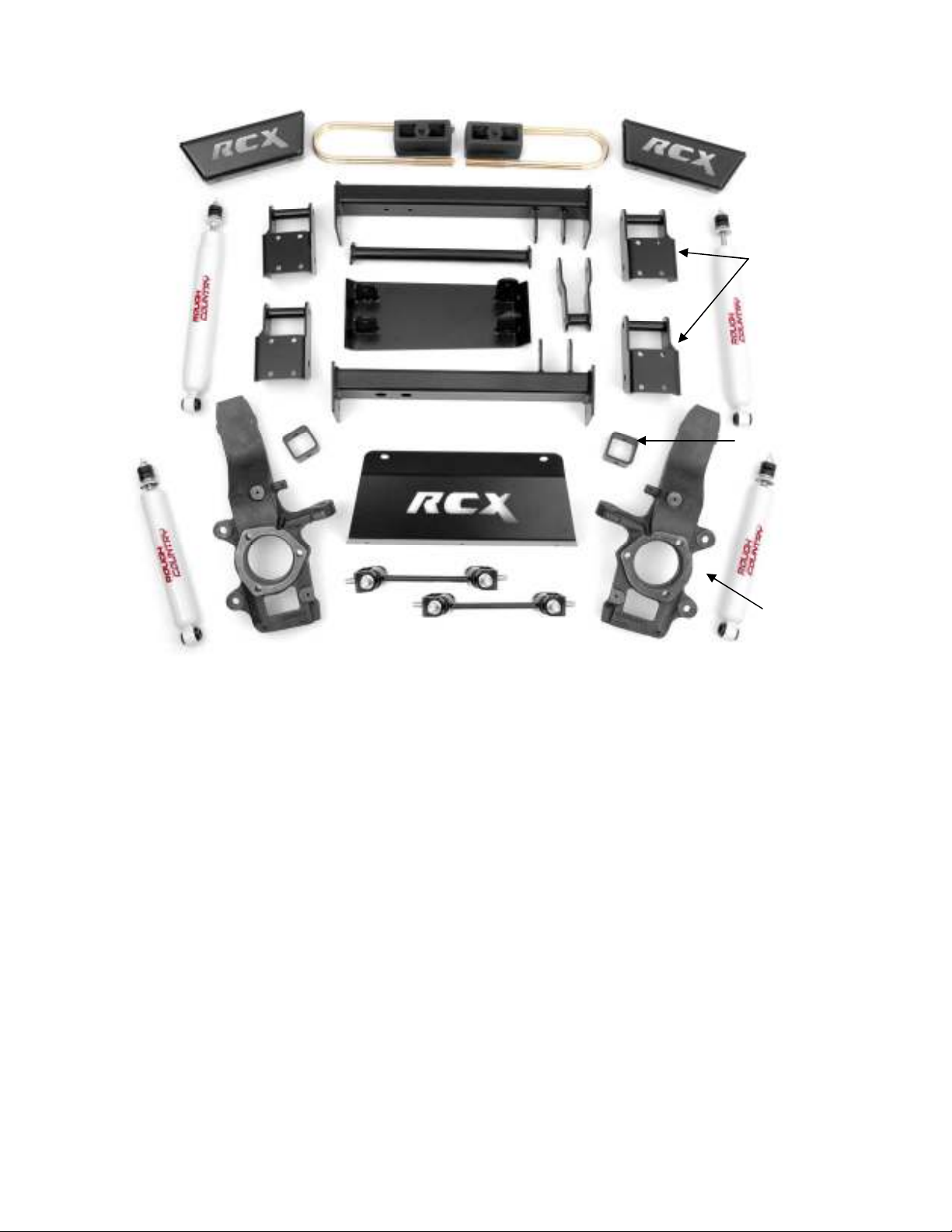
KIT CONTENTS
Torsion Bar Drop Brkt. –2
Rear
Shock –2
Pass.
Knuckle
Rear Blocks & u-bolts—2
Front Cross Member
Cr. Mbr
Spreader Bar
Diff Skid Plate
Rear Cross Member
Front Skid Plate
Drop Brkt –4
Pass Axle Brkt
Bump Stop Brkt—2
Front
Shock –2
Dr & Pass Knuckles
Driver Side Cross Member Brackets (2)
Pass Side Cross Member Bracket (2)
Front Cross Member
Rear Cross Member
Passenger Diff Drop Bracket
Sway Bar Links (2)
Sway Bar Link Brackets (2)
Bump stop Brackets (2)
Lower Skid Plate
Front Skid Plate
Cross Member Spreader Bar
Rear Blocks
Rear U-bolts
Front Shocks (650346)
Rear Shocks (650333)
Hardware Poly Bag
Front Sway Bar Link—2
Kit Contents:
Driver
Knuckle
PRE-INSTALLATION
Prior to beginning installation, carefully inspect the vehicle’s steering and driveline system paying close attention to the
tie rod ends, ball joints, and wheel bearings. Additionally, check steering to frame and suspension to frame attaching
points for stress cracks. The overall vehicle must be in excellent working condition before beginning installation. Repair
or replace all worn or damaged parts.
8mm socket 10mm socket
12mm socket 13mm socket
14mm socket 15mm socket
18mm socket 21mm socket
22mm socket 24mm socket
36mm socket 8mm wrench
10mm wrench 10mm wrench
12mm wrench 13mm wrench
15mm wrench 18mm wrench
21mm wrench 22mm wrench
24mm wrench Torque Ratchet
Torsion Bar Tool 17/64 drill bit
5/64 drill bit Sawsall
Drill Grinder
Jack stands (2) Floor jack
Tool Required List:
Torque Specs:
Size Grade 5 Grade 8
3/8” 30 ft/lbs 35 ft/lbs
7/16” 45 ft/lbs 60 ft/lbs
1/2” 65 ft/lbs 90 ft/lbs
9/16” 95 ft/lbs 130 ft/lbs
5/8” 135 ft/lbs 175 ft/lbs
Class 8.8 Class 10.9
6MM 5 ft/lbs 9 ft/lbs
8MM 18ft/lbs 23 ft/lbs
10MM 32ft/lbs 45ft/lbs
12MM 55ft/lbs 75ft/lbs
14MM 85ft/lbs 120ft/lbs
Safety Glasses and Gloves
FRONT INSTALLATION
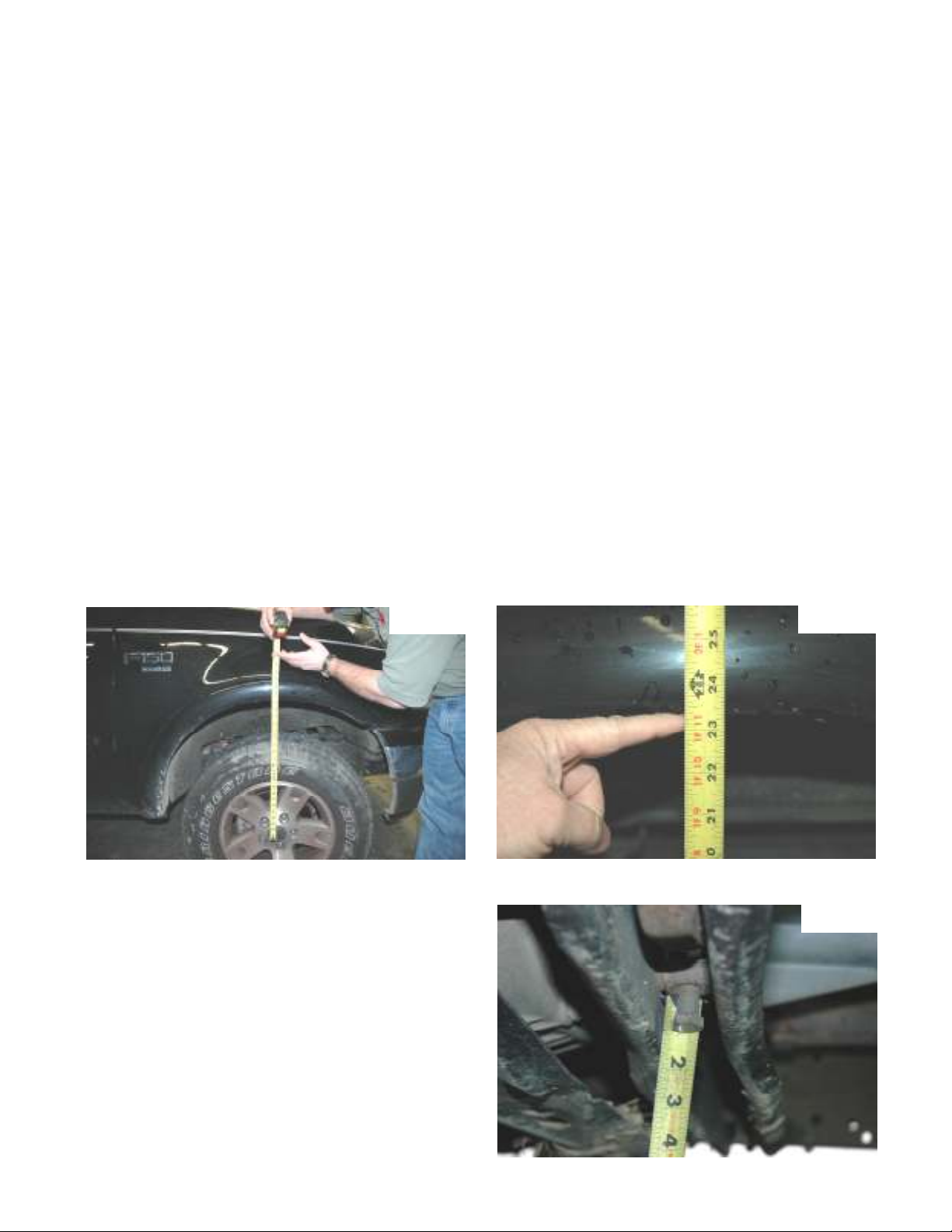
1. With the truck sitting on a level surface measure the distance from the center of the wheel to the bottom of the
fender. Record these Measurements. See Photo 1 & 2.
Front Driver ______ Front Passenger ______
Rear Driver ______ Rear Passenger ______
Photo 1
Photo 2
2. With the truck parked on a clean, dry, and level surface set the parking brake. Chock the rear wheels. Using a floor
jack raise the front of the truck and support the frame rail
with approved jack stands. NEVER WORK UNDER AN
Photo 3
UNSUPPORTED VEHICLE.
3. Using a 22 mm socket remove the lug nuts on the front
wheels and remove the front wheels
4. Measure the amount of thread showing on the torsion bar
adjuster bolts. See Photo 3. Drivers Side ______
Passenger Side ______ Using a 18mm socket remove the
adjuster bolt.
5. Using a Ford approved torsion bar tool, remove the torsion bar adjuster nuts and adjusters. Set aside, these will
be reused.
6. Using a 18 mm wrench and 18 mm socket remove the
upper shock nuts. Using a 13 mm wrench and 18 mm
socket remove the lower shock bolt. Retain the lower
hardware for reuse.
7. Using a 16 mm wrench and 15 mm socket remove the
stock sway bar links. See Photo 4.
8. Using a 13 mm wrench remove the brake caliper. Tie the
caliper up and out of the way. Do not let the caliper hang
from the brake line. Using a 18 mm socket remove the
brake caliper bracket.
9. Using a 8 mm socket remove the brake dust cover. This
will be reinstalled on the new knuckle.
10. Using a 8 mm socket remove the ABS hold down from the
knuckle. Using a 3/16 allen wrench remove bolt and
the sensor. Route this up to the frame rail. The allen bolt
will be reused.
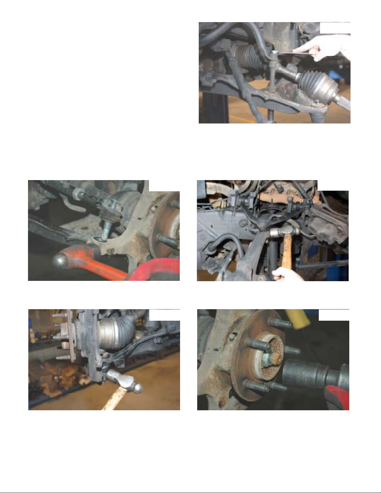
11. Using side cutters remove the cotter pin from the tie rod castle nut. Using a 21 mm socket remove the nut from the
tie rod. Using a hammer tap the knuckle as shown until the tie rod pops out. See Photo 5. Never hit the tie rod
itself.
12. Using side cutters remove the cotter key from upper ball joint. Using a 21 mm socket loosen the nut. Hit the knuckle
as shown until the ball joint pops loose. See Photo 6.
Photo 4
Photo 5
13. Using side cutters remove the cotter pin from the lower ball joint. Using a 24 mm socket remove the castle nut from
the ball joint. Using a hammer hit the knuckle as shown in Photo 7 until the ball joint pops free.
14. Using side cutters remove the cotter pin from CV shaft. Using a 36 mm socket remove the nut. See Photo 8.
Photo 7 Photo 8
Photo 6
15. Remove the nut from the upper ball joint and remove the knuckle from the truck. Using a 15 mm socket remove the
wheel bearing from the knuckle. Using a blunt punch and hammer remove the rear seal from the knuckle. Retain
hardware for reuse.
16. Using a 15 mm socket remove the six bolts that attaches each CV shaft to the front differential. Retain the bolts,
they will be reused.

17 Using a flat head screw driver remove the plastic cover on the front frame rail. See Photo 9. Using a 21 mm socket
and 24 mm wrench remove the front and rear lower control arm bolts. Be careful the torsion bar will come out with
the control arm. See Photo 10. Remove the torsion bar. Scribe a mark on the torsion bar to note it indexing in relationship to the control arm. The bars are to be reinstalled in same relationship as removed.
Photo 9 Photo 10
18 Position a floor jack or jack stand under the differential
to allow the differential bolts to be removed.
19 Using a 15 mm socket and 18 mm wrench remove the
passenger side upper bolt as shown in Photo 11 that
secures the differential to the frame. Retain the stock
hardware for reuse.
20. Using a 15mm socket and 18mm wrench remove the
driver side upper and lower differential bolts that secure the differential to the frame. See Photo 12 & 13.
Retain the stock hardware for reuse.
Photo 12 Photo 13
Photo 11
21. Using a 15 mm socket remove the bolts securing the rear
cross-member to the frame as shown in Photo 15 and
remove from the vehicle.
Photo 15

22. Unplug the Differential vacuum hoses. See Photo 16. Gently pull down on the hoses giving it 5 inches of slack. Using
a 12 point 12 mm socket remove the four bolts that secure
the drive shaft to the differential. Retain hardware for reuse.
23. Locate the 4 cross member drop brackets and assemble
them using the 7/16” x 1 1/4” bolts, thick washers, and nylock nuts with the cross members as shown in Photo 17.
Only three bolts per side will be used. Do not tighten
at this time.
24. With the differential still supported with jack stands or a
floor jack and using the 9/16 x 5 1/5 bolts, install the crossmembers into the lower control arm sockets as shown in
Photo 18. The bolts will be installed from the front to the
rear. Do not tighten at this time.
Photo 16
Photo 17
Driver Rear Diff Mount
Driver Side Rear Shown
25. Assemble the front cross member the same as the rear with the supplied 7/16” x 1 1/4” bolts, washers/nuts. Only
three bolts per side will be used. DO not tighten at this time.
26. Install in the front factory location as shown in Photo 19 with the supplied 9/16” x 5 1/2” bolts. Do not tighten at this
time.
27. Install the diff drop bracket on the passenger side as shown in Photo 20 with the factory hardware on the frame and
the supplied 12mm x 100m bolts, washers /nuts on the differential. Do not tighten at this time.
Photo 19
Photo 18
Photo 20

28. Install the skid plate on the drivers side as shown in Photo 21 on the differential tabs with the supplied 12mm x
100mm bolts, washers/nuts. Do not tighten at this time.
29. Remove the torsion bars from the lower control arms and install the lower control arms into the new brackets. With
the factory hardware. Slightly tighten the bolts. See Photo 22.
Photo 21
30. Tighten the 12 cross member bracket bolts to 45 ft lbs. Tighten the upper cross member bolts to 65 ft lbs.
31. Lightly pull the vacuum hose down and reinstall on the differential.
32. Locate the supplied spreader bars and install as shown in Photo 23 using the supplied 4-3/8” x 1” bolts/washers &
nuts. Tighten with a 9/16 wrench.
33. Using a 12 mm 12 point socket install the drive shaft with factory bolts.
34. Using a 15 mm socket and a 18 mm wrench remove the front and rear bolts from the Torsion bar adjuster bracket.
Using a 18 mm socket and 18 mm wrench remove the center bolt. See Photo 24. Retain the two factory outer
bolts for reuse.
Photo 23
Photo 22
Photo 24
35. Install the supplied 12mm x 1 1/4” crush sleeve as shown in Photo 25 on the stock torsion bar cross member.
36. Locate the torsion bar drop brackets and install as shown using the supplied 7/16” x 1 1/4”bolts/washers & nuts.
See Photo 26. Do not tighten at this time.
Photo 25
Photo 26

37. Install the factory cross member in the drop brackets as
shown with the factory hardware on the two outer bolts
and using the 10mm x 65mm bolt / washer & nuts in the
center. Do not tighten at this time. Slide the torsion bars
into the lower control arms.
38. Raise the torsion bar adjuster bracket into position in
the torsion bar cross member and install using factory
hardware.
39. Make sure that both sides of the drop bracket / torsion
bar cross member assembly are straight with the frame
tighten all hardware to 45 ft lbs.
40. Using the factory CV bolts reinstall the CV shafts on the
differential as shown in Photo 27 using a 12mm 12
point socket.
41. Locate the bearing assembly removed from the stock
knuckle. If the seal is in good condition, install the seal in the new knuckle. If necessary purchase new seals.
Install the bearing into the new knuckle with the factory hardware using a 15mm wrench. See Photo 28.
42. Reinstall the ABS sensors & wire clip as shown in Photo 29 using a 3/16” allen head wrench and install wire clip
onto new knuckle using a 8mm wrench.
Photo 27
Photo 28
43. Install on the lower and upper ball joints as shown in
Photo 30 & 31 with stock hardware and supplied cotter
pin. Tighten using a 21mm wrench for the upper ball joint
and a 24mm on the lower ball joint.
44. Install the stock tie rod on the new knuckle with stock
hardware using a 21mm wrench. Install supplied cotter
pin.
45. Install the bump stop extension bracket as shown in
Photo 32 using the supplied 1/2” x 1 1/2” bolts/washers &
nuts. Install the factory bump stop on top of the bracket
using factory hardware.
Photo 29
Wire Clip
Photo 30
Photo 31
Photo 32

46. Using a 10 mm socket remove the brake line bracket from the frame rail. Measure down 2.5 inches and drill a hole
using a 17/64” bit. Using the factory screw reinstall the hold down in the frame. See Photo 33 & 34.
Photo 33 Photo 34
47. Trim the dust shield as shown and reinstall on the knuckle using it as a template to locate the 1/4” hole to be drilled.
Mark the hole, drill the 1/4’ hole and install on the knuckle. See Photo 35.
48. Using a 18 mm socket install the caliper hold down bracket.
49. Using a 13 mm wrench install the brake caliper.
50. Using a 36 mm socket install the outer CV shaft nut and torque to 85 ft lbs. Install the supplied cotter key.
51. Install the new sway bar link bracket on the lower control arm as shown in Photo 36 with the supplied 12mm x
35mm bolts, flat washer and flange lock nut. Do not Tighten at this time.
52. Install the sway bar link bracket on the sway bar as shown in Photo 36 with the supplied 12mm x 35mm bolts, flat
washer and flange lock nut. Do not tighten at this time.
53. Install the sway bar link in the upper and lower bracket with the supplied 12mm x 65mm bolts with the head of the
bolts toward the rear of the vehicle.
54. Tighten all sway bar hardware using a 18mm & 19mm socket & wrench.
55. Install the front shock part number 650346 in the factory location with the factory hardware on the bottom of the
shock. Tighten with a 9/16” wrench on the upper and a 13mm & 18mm wrench for the lower.
56. Using the Ford approved torsion bar tool install the torsion bar adjusters and adjuster nuts. Using a 18 mm socket
set the torsion bars to factory setting.
Photo 35
Photo 36

57. Install the supplied skid plate using the supplied 3-3/8” x
1 1/4” & 21/2” x 1 1/2” self tapping bolts. See Photo 37.
58. Tighten all hardware on the cross members, upper control arms, and diff drop brackets. Do not tighten the
lower control arms until the vehicle is on the ground
and at ride height..
59. Install the wheels and tires and torque to factory.
60. Lower vehicle to the ground, set the ride height and
tighten the lower control arms.
Photo 37
1/2” x 1 1/2’ bolts
3/8” x 1 1/4” bolts

REAR INSTALLATION
1. Raise the rear of the vehicle and support with approved jack stands. Remove the rear wheels.
2. Using a 18 mm socket and 18 mm wrench remove the lower shock bolt. Using a 18 mm wrench remove the upper
shock nut. Retain stock hardware.
4. Using a 21 mm socket remove the u-bolts. See Photo 38. Doing one side at a time.
5. Install the new blocks under the factory block and new u-bolts and tighten to 85 ft lbs. See Photo 39.
Photo 38 Photo 39
6. Install new shocks part number 650333 with new nut for the top and factory bolt and nut on the lower.
7. Install the wheels and tires tighten to factory specs and lower vehicle on the ground.
OPTIONAL EQUIPMENT
OPTIONAL STEERING STABILIZER:
PART # 87343
Please contact your local Rough Country Dealer for more information.
POST INSTALLATION INSTRUCTIONS
1. Lug nuts should be check after 50 miles and all nuts and bolts should be checked and tightened after 500 miles. All
parts should be checked every 3000 miles for the life of the vehicle.
2. Recheck brake hoses and lines for proper clearances.
3. Perform steering sweep to check for appropriate tire clearance. Note- Some oversized tires may require trimming of
the bumper and valance
4. If new tires are installed that are more than 10% taller than original tires, the speedometer must be recalibrated for
the anti-lock brake system (if applicable) to function properly. Contact an authorized Ford dealer for details on recalibration.
5. Adjust headlights back to proper settings.
6. Have a qualified alignment center realign front end to factory specs.
7. Install “Warning to Driver” decal on sun visor.

Thank you for purchasing a Rough Country Suspension System.
 Loading...