

Page 1
92134200
2003-2012
Thank you for choosing Rough Country Suspension for your Off Road needs.
Rough Country recommends a certified technician installs this system. In addition to these instructions, professional
knowledge of disassemble/reassembly procedures as well as post installation checks must be known. Attempts to
install this system without this knowledge and expertise may jeopardize the integrity and/or operating safety of the vehicle. Average professional install time for this kit is 2-4 hours.
Please read all the instructions before beginning the installation. Check the kit hardware against the kit contents list on
the last page. Be sure you have all the needed parts and understand where they go.
As a general rule, the taller a vehicle is the easier it will roll. We strongly recommend, because of rollover possibility,
that the vehicle be equipped with a functional roll-bar and cage system. Seat belts and should harnesses should be
worn at all times. Avoid situations where a side rollover may occur.
Also check the steering stabilizer. It is a good idea when adding larger than stock tires to go with a larger bore steering
stabilizer or a dual unit for tires 35” and above. Inspect the stabilizer and replace as necessary.
Braking performance and capability are decreased when significantly large/heavier tires and wheels are used. Take
this into consideration while driving.
Do no add, alter, or fabricate any factory or after-market parts which increase vehicle height over the intended height
of the Rough Country product purchased. Mixing component brands, lifts, and/or combining body lift with suspension
lifts voids all warranties. Rough Country makes no claims regarding lifting devices and excludes any and all implied
claims. We will not be responsible for any product that is altered.
The relocation brackets are used to flatten out the angle of the control arms to maintain your factory handling characteristics of the vehicle. These brackets are designed to use with Rough Country’s 5” Dodge 2500/3500 kit using factory
control arms or adjustable arms at factory lengths.
Any vehicle equipped with any Rough country product must have the “Warning to Driver” decal installed on the sun
visor or dash. The decal is to act as a constant reminder for whoever is operating the vehicle of its unique handling
characteristics. INSTALLING DEALER—It is your responsibility to install the warning decal and to forward
these installation instructions to the vehicle owner for review and to be kept in the vehicle for its service life.
Tools Needed
13mm 5/8”
14mm 11/16”
15mm 1 1/16”
18mm 7/16 Drill bit
19mm
21mm
22mm
24mm
Jack stands
Floor jack
2500/3500 CONTROL ARM DROP BRACKETS
Product Use Information
Notice to Dealer and Vehicle Owner
Page 2
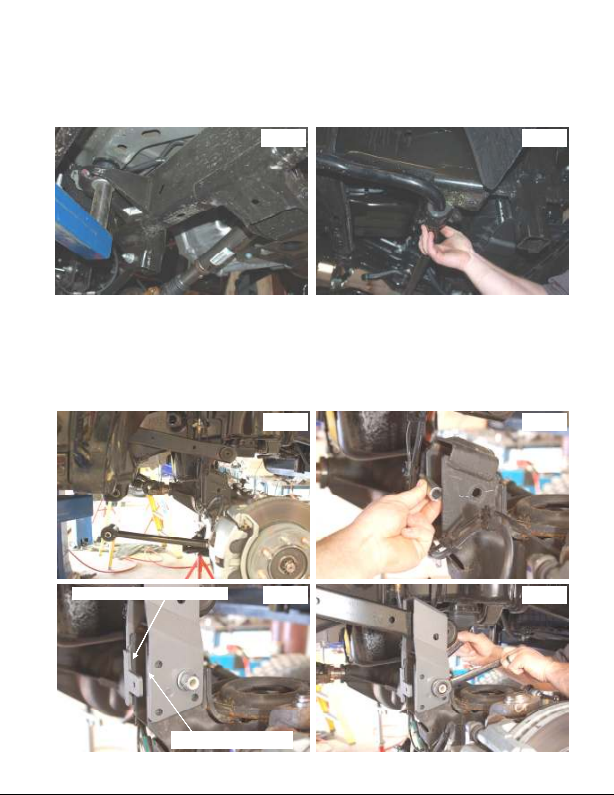
1. When raising vehicle using a jack or lift do not place lift arms or jack stands on frame between lower control arm and transmission cross-member. This is done so new parts can be installed. See Photo 1
2. Remove the track bar bolt on frame side using a 21mm socket. Then raise vehicle and remove tires and wheels using 22mm
socket
3. Remove the four bolts from the sway-bar mounts on frame using 15mm socket. See Photo 2 Using a 13mm socket remove
brake line bracket from axle on driver and passenger side. Disconnect drag link from pitman arm using a 21mm wrench and a
hammer to strike the end of the pitman arm breaking loose the taper.
Photo 1
4. Support front axle with a jack or jack stands. Using a 18mm wrench remove upper shock nut. Then using a 15mm wrench remove upper shock mount. Use a 21mm socket for lower shock bolts. Remove shocks.
5. Raise vehicle up and remove coil springs
6. On passenger side remove upper control arm bolt on axle side using a 21mm socket and wrench. Remove bolt from lower control arm on frame side using a 21m wrench and a 1 1/16 socket. Placing a jack under passenger side on axle slowly move axle
forward until upper control arm can be move above axle See Photo 3
7. Install the supplied sleeve then install upper control arm bracket using the supplied 9/16 x 5” long bolts, washers, and nuts.
Make sure new bracket and old upper control arm mount are straight with one another then tighten bolt using a 21mm and a
22mm wrench. See Photo 4, 5, 6. On some models grinding is required on the factory upper control bracket edge. See Photo 5
Photo 3 Photo 4
Photo 2
GRINDING MAY BE REQUIRED
LINE UP OUTSIDE EDGE
Photo 5
Photo 6
Page 3
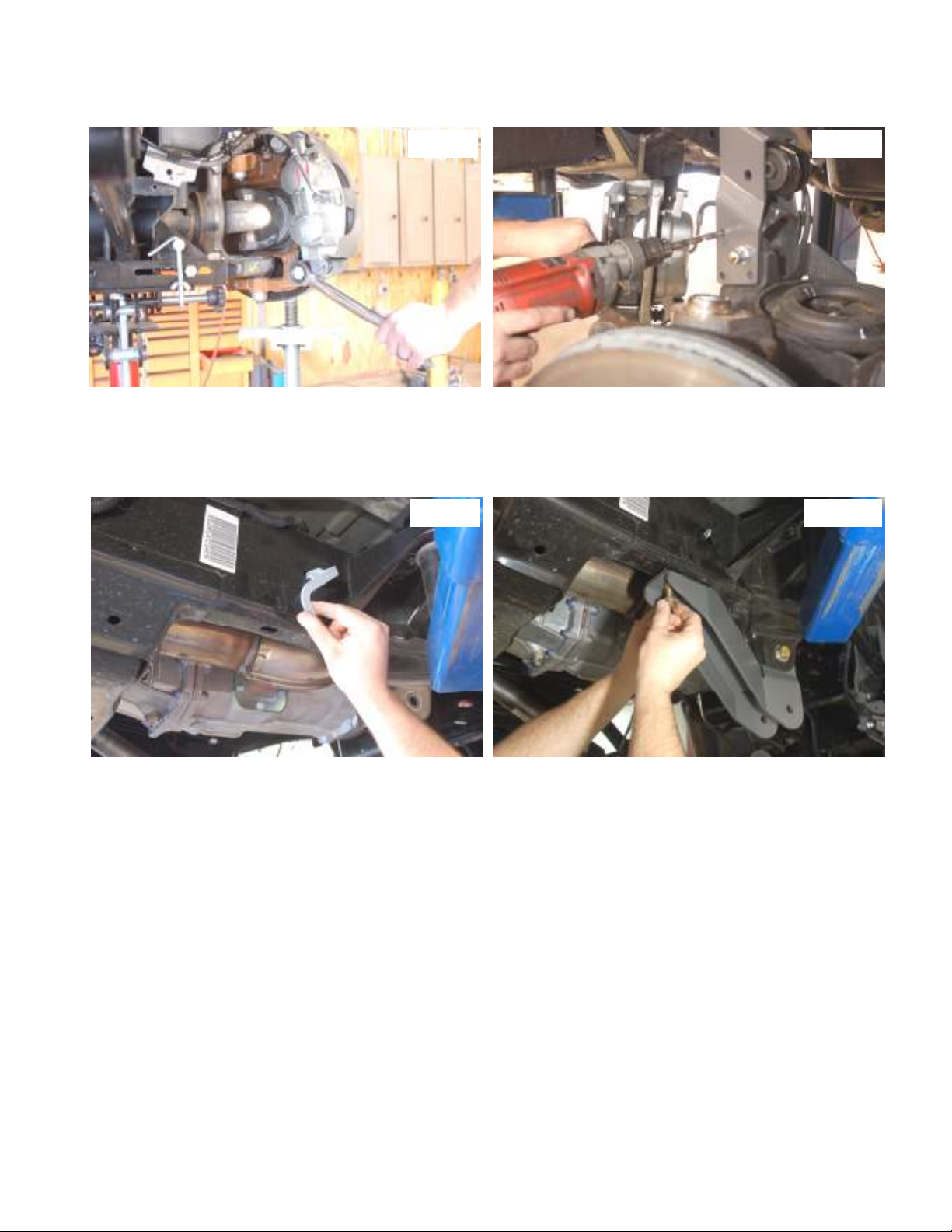
8. Using a 24mm socket remove brake caliper bolts and hang caliper out of the way. See Photo 7 Using control arm drop bracket
as a guide drill all six holes using a 7/16 drill bit. Install the 7/16 x 1.5” long bolts, washers, and nuts into drilled holes. Tighten
bolts using 5/8 and a 11/16 wrench. See Photo 8
Photo 8 Photo 7
9. Reinstall brake caliper with stock hardware using a 24mm socket to tighten.
10. Install the supplied flag nut into slotted hole behind body mount. See Photo 9 Install lower control arm drop bracket using supplied 5/8 x 4.5” long bolt, nut, and washer. Use the 1/2 x 1.5” bolt, washer, and nut for rear of drop mount. See Photo 10 Install
lower and upper control arms into pockets using stock hardware. Tighten 1/2 bolt using a 19mm socket and wrench, and tighten
the 5/8 bolt using 24mm wrench and socket. Do not tighten lower and upper control arm pivot bolts at this time.
Photo 9 Photo 10
11. Install coil spring and shock at this time using stock hardware for lower. Use a 14mm wrench for upper shock nut and a 21 mm
socket for lower shock bolt.
12. Repeat steps 4-11 on the driver side
13. Reinstall brake line brackets on the driver and passenger side lower control arm drop brackets using stock hardware and a 13mm
socket to tighten.
14. Connect the draglink back to the pitman arm and tighten using a 21mm wrench and also connect the sway-bar to the frame using
factory hardware and a 15mm socket.
15. Install tires and wheels and tighten with a 22 mm socket and lower truck to the ground.
16. Reinstall the track bar to the frame with the factory bolt, tighten with a 21mm socket. If the track bar sleeve and frame bracket
hole do not line up, start the truck and by turning the steering wheel this will move the frame to align the bolt holes.
17. Tighten the upper control arm bolts using a 21mm socket and wrench, and tighten the lower control arm bolts using a 21m
wrench and a 1 1/16 socket.
Post Installation
1. Check all fasteners for proper torque. Check to ensure there is proper clearance between all rotating, mobile, fixed, and heated
parts.
2. Perform steering sweep to check the distance between tires, break hoses, steering components, and sway-bar.
3. Check the torque of all fasteners after the first 500 miles after install.
Page 4
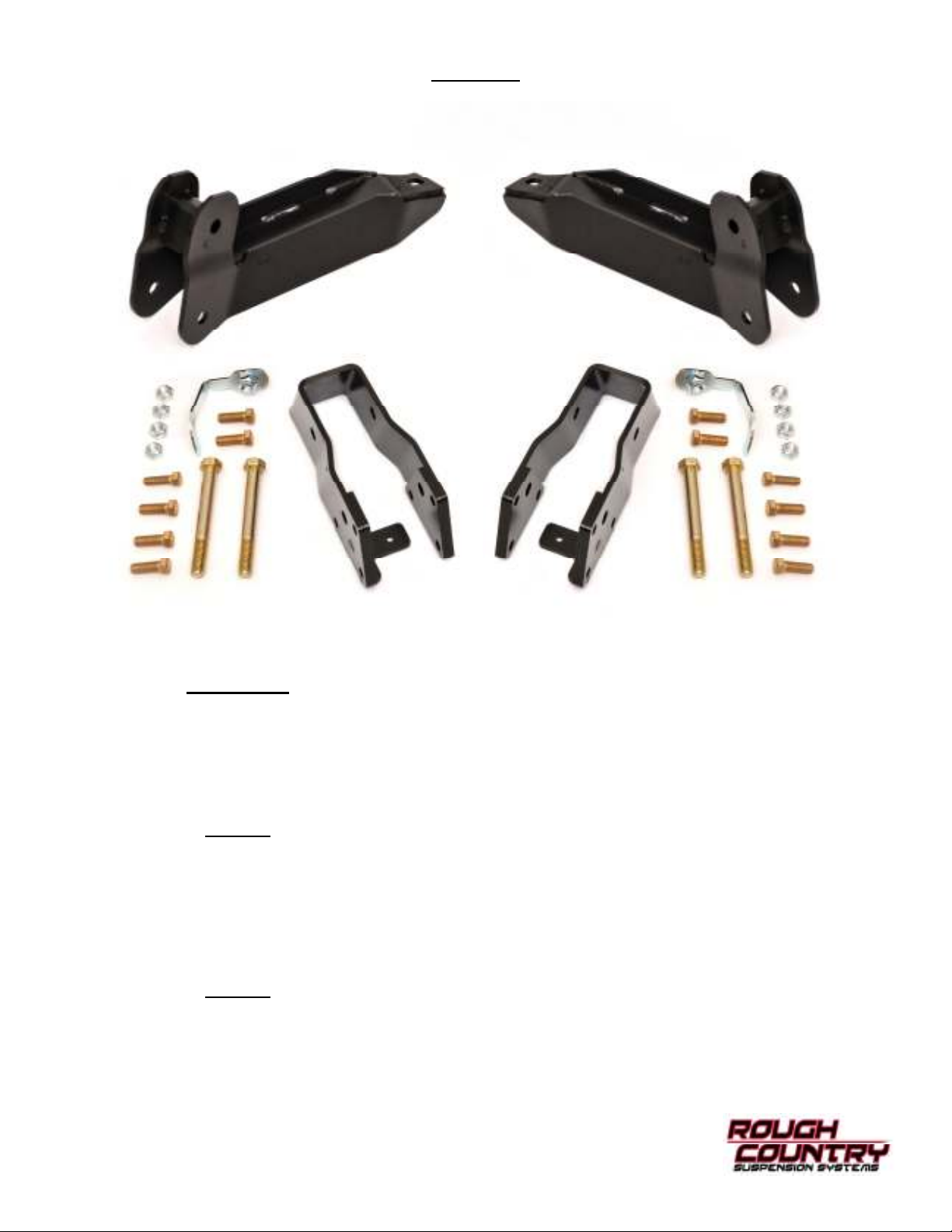
Kit Picture
Kit Contents
1- Lower driver side control arm bracket
1- Lower passenger side control arm bracket
2- Upper control arm brackets
1- Driver side flag nut
1- Passenger side flag nut
1342Bag1
2- Sleeves 14mm x .875 x 2.35
2- 9/16 x 5” bolts
4- 9/16 nylocks
2- 9/16 washers
12- 7/16 x 1.5” bolts
12- 7/16 nylocks
24- 7/16 washers
1342Bag2
2- 5/8 x 4.5” bolts
2- 5/8 nylocks
4- 5/8 washers
2- 1/2 x 1.5” bolts
2- 1/2 washers
 Loading...