

Page 1
92397000
05 & 10 2WD Dakota & Mitsubishi Raider
Thank you for choosing Rough Country for all your suspension needs.
Rough Country recommends a certified technician install this system. In addition to these instructions, professional
knowledge of disassemble/reassembly procedures as well as post installation checks must be known.
Please read instructions before beginning installation. Check the kit hardware against the kit contents list on the back
page. Be sure you have all needed parts and know where they go. Also please review tools needed list and make sure
you have needed tools.
PRIOR TO INSTALLTION NOTE:
Under hard acceleration in 4x4 high, stock Dodge Ram’s often have a front end vibration or shutter. This vibration or shutter exist due to the design of the motor and differential mounts and is inherent in the vehicle. This
vibration or shutter may be more pronounced after a leveling kit is installed due to additional torque from modi-
fied driveshaft angles. This does not indicate a problem, but should be a consideration prior to installation
.
PRODUCT USE INFORMATION
As a general rule, the taller a vehicle is, the easier it will roll. Seat belts and shoulder harnesses should be worn at all
times. Avoid situations where a side rollover may occur.
Generally, braking performance and capability are decreased when larger/heavier tires and wheels are used. Do not
add, alter, or fabricate any factory or after-market parts to increase vehicle height over the intended height of the Rough
Country product purchased.
Rough Country makes no claims regarding lifting devices and excludes any and all implied
claims. We will not be responsible for any product that is altered. If question exist we will be happy to answer any questions concerning the design, function, and use of our products.
This suspension system was developed using a 33X12.50/17, tire with factory wheels.
NOTICE TO DEALER AND VEHICLE OWNER
Any vehicle equipped with any Rough Country product should have a “Warning to Driver” decal installed on the inside of
the windshield or on the vehicle’s dash. And should act as a constant reminder of its unique handling characteristics.
INSTALLING DEALER - it is your responsibility to install the warning decal and forward these installation instructions on
to the vehicle owner for review. These instructions should be kept in the vehicle for its service life.
INSTALLATION INSTRUCTIONS
1. Jack up the front of the vehicle and support the vehicle with jack stands, so that the front wheels are off the ground.
2. Using 22mm socket remove the front tires/wheels.
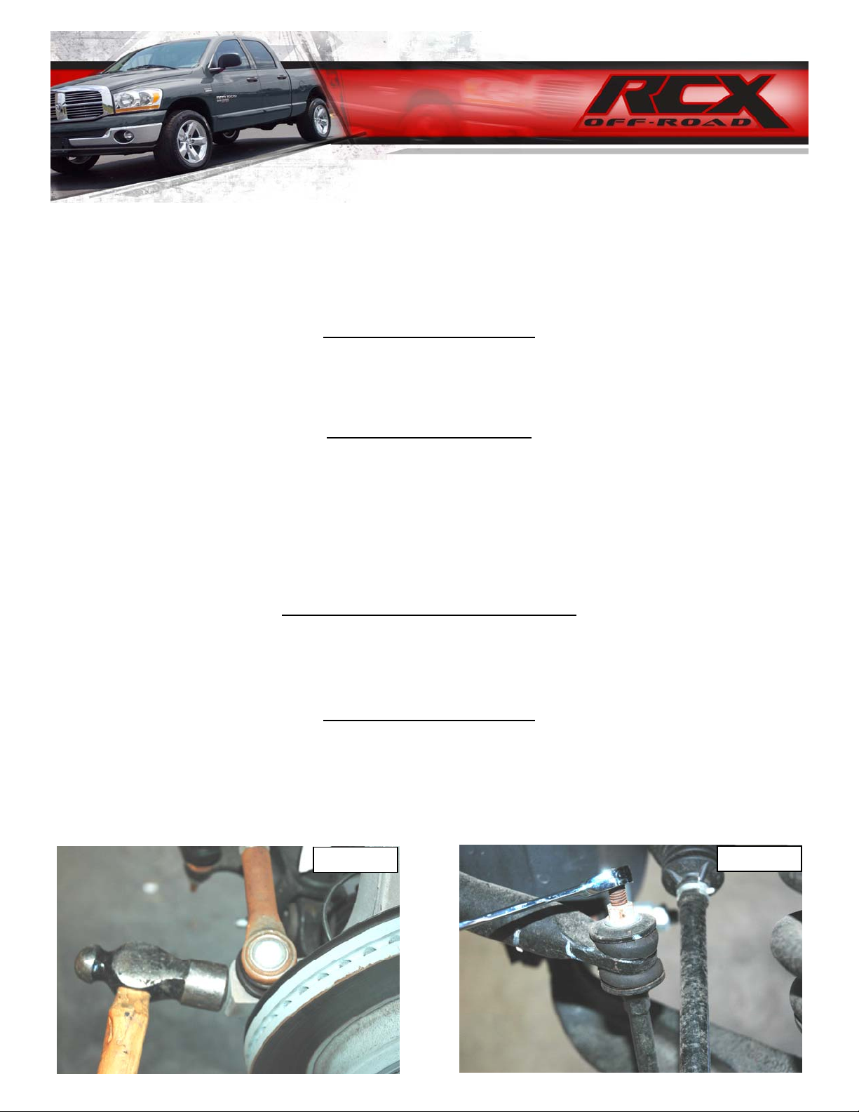
3. Using 21mm socket remove the nut from the steering linkage. Using a hammer hit on the side of the knuckle as
shown, and remove the linkage from the knuckle. Push linkage forward to make room for installation. Retain factory
hardware See PHOTO 1.
4. Using a 15mm wrench, remove the sway bar nut, and bushings allowing the sway bar to drop. Retain factory hard-
ware. See PHOTO 2.
PHOTO
PHOTO 2
Page 2
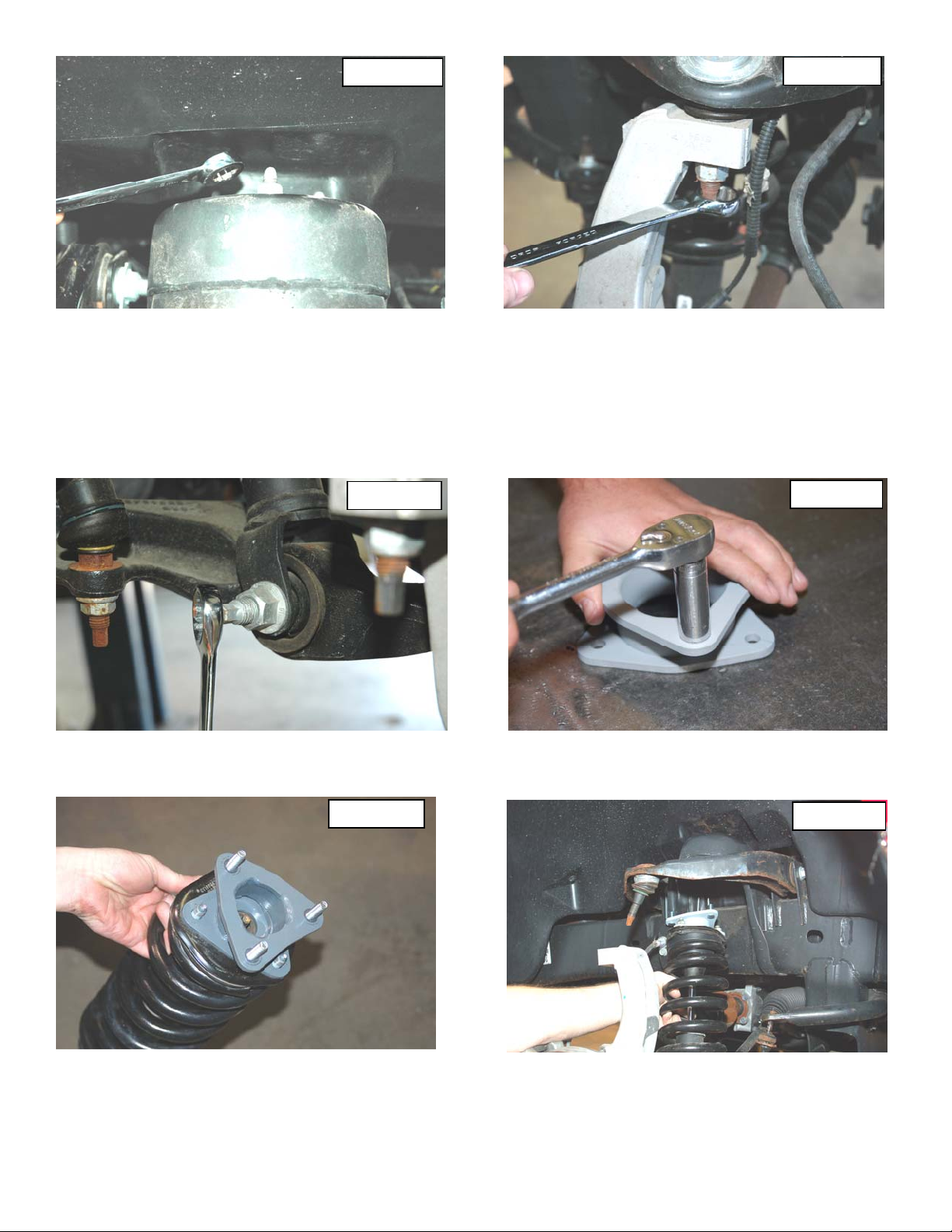
PHOTO 3
5. Using a 15mm Socket, remove the strut nuts on the upper strut tower. See PHOTO 3
6. Place jack stand under the knuckle for support. Using 21 mm socket remove upper ball joint nut. Using a hammer hit
the knuckle to allow the ball joint to separate from the upper control arm See PHOTO 4. Do not allow the knuckle to
pull out far enough that it pulls the shaft out of the differential.
7. Using a 24mm socket and 21mm wrench, remove the strut bolt from the lower control arm and remove the strut as-
sembly from the vehicle. Retain the factory lower bolt for reassembly. Note the direction of the bolt for reassembly.
See PHOTO 5.
8. Locate the supplied 3/8” stud extensions. Using a 9/16” socket snug self clinching stud in the new spacer as shown
in Photo 6. The stud should clinch with about 35-45 ft/lbs of torque. Do not over torque the nut.
PHOTO 4
PHOTO 5
9. Place the strut extension on the strut and tighten using the factory hardware. See PHOTO 7.
10. Install the strut assembly as shown in PHOTO 8 into the strut tower and start using the supplied 3/8” nuts.
11. Install the lower strut bolt in the original position that it was removed. See PHOTO 8. Torque to factory specs.
PHOTO 7
PHOTO 6
PHOTO 8
12. Using a floor jack, raise the lower control arm and connect the upper ball joint on the upper control arm to the spin-
dle. Torque to manufacturer specs.
13. Using a 21mm socket reinstall the steering linkage nut .
14. Repeat steps 3-21 on opposite side of vehicle
15. Using 15 mm wrench reinstall sway bar bushings and nut using factory hardware. Torque to factory specs.
16. Install the wheels / tires.
all bolts to factory specifications.
Jack up the vehicle and remove the jack stands. Lower the vehicle to the floor and torque
Page 3
REAR INSTALLATION
(IF PURCHASED WITH KIT)
1. Jack up the rear of the vehicle and place jack stands underneath the frame rail.
2. Remove the tires and wheels.
3. Remove rear shocks using a 21mm wrench. Save the stock hardware it will be used later.
4. Place the floor jack underneath the axle and remove the stock u-bolts. Lower the axle down to allow the blocks to
be installed in between the stock block and the spring perch. Install the new u-bolts and secure with fastene rs provided.
5. Assemble the rear shocks 650396, and install in the stock position with sto ck hardware, using a 21mm wrench.
POST INSTALLATION
1. Check all fasteners for proper torque. Check to ensure there is adequate clearance between all rotating, mobile,
fixed and heated members. Check steering for interference and proper working order. Test brake system.
2. Perform steering sweep. The distance between the tire sidewall and the brake hose must be checked closely. Cycle
the steering from full turn to full turn to check for clearance.
3. Re torque all fasteners after 500 miles. Visually inspect components and re torque fasteners during routine vehicle
service.
4. Readjust headlights to proper settings and take truck in for a front-end alignment to a qualified alignment profes-
sional.
Page 4

KIT CONTENTS
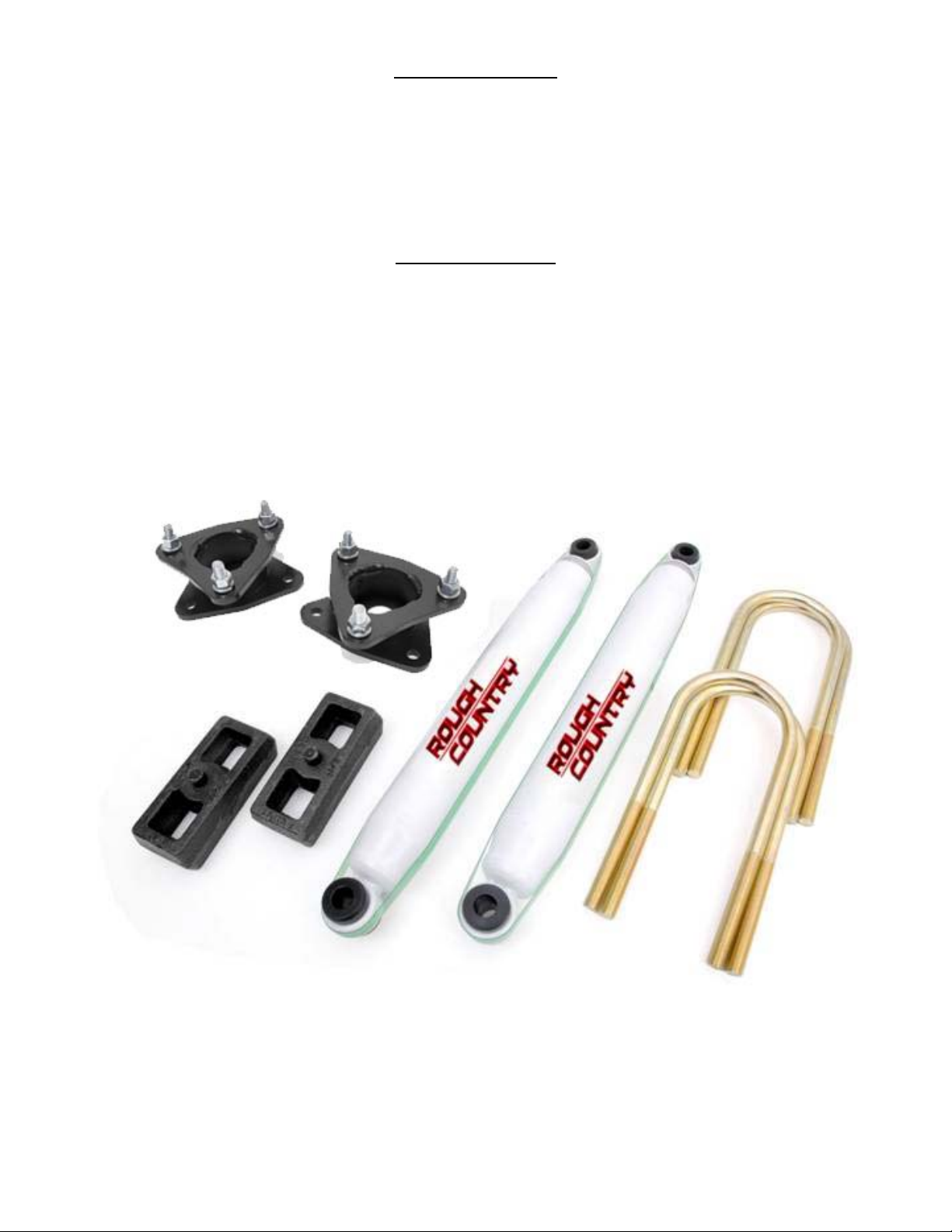
2-Front Strut Extensions
1-Kit Bag that includes
6-3/8” Studs
6-3/8” nuts
6-3/8 lock washers
395S
650396 Shock (2)
1.5” Blocks and U-Bolts
TOOLS NEEDED:
19 mm Socket
Hammer
19 mm Wrench
17 mm Wrench
14 mm Socket
22 mm Socket
13/16” Socket
Floor Jack
Jack Stands
395S Pictured with rear blocks/ U-bolts and Shock Absorbers
Thank you for purchasing a Rough Country Suspension System.
 Loading...