

Page 1
E-M-HW4v2-Main_13
Rotronic AG
Bassersdorf, Switzerland
Document code
Unit
HW4 software v.2 General instructions and functions
common to all devices
Instruction Manual
Document Type
Page
1 of 165
Document title
HW4 Software version 2
General instructions and functions common to all devices
© 2008; Rotronic AG E-M-HW4v2-Main_13
Page 2

E-M-HW4v2-Main_13
Rotronic AG
Bassersdorf, Switzerland
Document code
Unit
HW4 software v.2 General instructions and functions
common to all devices
Instruction Manual
Document Type
Page
2 of 165
Document title
Table of contents
1 ORGANIZATION OF THE HW4 MANUALS ........................................................................ 5
2 OVERVIEW ........................................................................................................................... 6
2.1 HW4 Standard Edition ................................................................................................................. 6
2.2 HW4 Professional Edition ............................................................................................................ 6
2.3 HW4 Lite ...................................................................................................................................... 7
2.4 HW4 Professional with OPC Server ............................................................................................. 7
2.5 HW4 Professional with AwQuick .................................................................................................. 7
2.6 HW4 Professional Trial Version ................................................................................................... 7
2.7 HW4 Validated ............................................................................................................................. 7
3 NEW IN VERSION 2.1.0 OR HIGHER ................................................................................. 8
3.1 HW4 v 2.1.0 ................................................................................................................................. 8
3.2 HW4 v 2.1.1 ................................................................................................................................. 9
3.3 HW4 v 2.2.0 ................................................................................................................................. 9
3.4 HW4 v 2.3.0 ................................................................................................................................10
4 INSTALLATION .................................................................................................................. 12
4.1 Software Licensing Agreement ...................................................................................................12
4.2 HW4 requirements ......................................................................................................................12
4.3 Installing HW4 .............................................................................................................................14
4.4 Updating HW4 to a newer version ..............................................................................................18
4.5 Uninstalling HW4 (full uninstall) ..................................................................................................18
5 CONNECTING DEVICES TO THE HW4 PC ...................................................................... 19
5.1 Definition: masters and slaves (HW4 Professional) ....................................................................19
5.2 Connection methods for master devices .....................................................................................19
5.3 Devices used as RS-485 slaves (HW4 Professional) .................................................................19
6 PREPARING FOR DEVICE CONNECTION ...................................................................... 21
6.1 Physical serial port ......................................................................................................................21
6.2 Bluetooth virtual serial port .........................................................................................................21
6.3 USB port .....................................................................................................................................21
6.4 Ethernet (TCP/IP) connection .....................................................................................................24
6.5 RS-485 slaves: address and Baud rate requirements .................................................................29
7 INITIAL START-UP ............................................................................................................ 31
7.1 Language selection .....................................................................................................................31
7.2 Product key and registration .......................................................................................................32
7.3 Automatic device discovery during initial start-up .......................................................................34
7.4 Creating the first user (HW4 Professional) ..................................................................................35
7.5 Access to functions and screens (HW4 Professional) .................................................................35
8 SEARCHING FOR DEVICES WITH HW4 .......................................................................... 36
8.1 Searching for master devices......................................................................................................36
8.2 Searching for RS-485 slaves (HW4 Professional) ......................................................................36
9 HW4 MAIN SCREEN .......................................................................................................... 37
9.1 Device Tree (left pane) ...............................................................................................................38
9.2 Right pane in Device View mode ................................................................................................41
9.3 Right pane in Group View mode .................................................................................................49
10 HW4 MAIN MENU BAR ...................................................................................................... 53
10.1 File ..............................................................................................................................................53
10.2 Devices and Groups ...................................................................................................................54
© 2008; Rotronic AG E-M-HW4v2-Main_13
Page 3

E-M-HW4v2-Main_13
Rotronic AG
Bassersdorf, Switzerland
Document code
Unit
HW4 software v.2 General instructions and functions
common to all devices
Instruction Manual
Document Type
Page
3 of 165
Document title
10.3 View ............................................................................................................................................58
10.4 Settings and Tools ......................................................................................................................59
10.5 Help ............................................................................................................................................60
10.6 Shortcut buttons ..........................................................................................................................60
11 ETHERNET CONFIGURATION TOOL .............................................................................. 61
12 USERS AND PASSWORDS (HW4 Professional) ............................................................ 62
12.1 Minimum user rights ....................................................................................................................62
12.2 Additional user rights ..................................................................................................................63
12.3 Creating and logging-on the first user .........................................................................................64
12.4 User table form ...........................................................................................................................67
12.5 Menu bar .....................................................................................................................................67
12.6 User login security ......................................................................................................................69
13 COLUMN HEADERS .......................................................................................................... 69
14 HW4 GLOBAL SETTINGS ................................................................................................. 72
14.1 View Tab .....................................................................................................................................72
14.2 General Tab ................................................................................................................................74
14.3 Language/Unit System Tab ........................................................................................................77
14.4 File Locations Tab .......................................................................................................................79
14.5 Graph Settings Tab .....................................................................................................................81
14.6 Alarm Settings Tab (HW4 Professional) .....................................................................................84
14.7 Events Tab (HW4 Professional) ..................................................................................................86
15 USER EVENTS (HW4 Professional) ................................................................................. 87
15.1 Menu bar .....................................................................................................................................88
16 ALARM TABLE (HW4 Professional) ................................................................................ 89
16.1 Alarm acknowledgement .............................................................................................................90
16.2 Alarm table menu bar and buttons ..............................................................................................91
17 PSYCHROMETRIC CONVERSIONS ................................................................................. 93
18 DEVICE PROTECTION ...................................................................................................... 94
19 DATA LOGGING - directly on the PC .............................................................................. 96
19.1 Start logging data to the PC ........................................................................................................96
19.2 Stop logging data to the PC ........................................................................................................98
20 ACCESSING LOG FILES, PROTOCOLS AND EVENT FILES ......................................... 99
21 VIEW / SIGN A PROTOCOL ............................................................................................ 101
21.1 Protocol viewer menu bar .........................................................................................................103
22 VIEW / SIGN A LOG FILE ................................................................................................ 104
22.1 Opening a log file in HW4 View Data ........................................................................................104
22.2 View Data menu bar .................................................................................................................108
22.3 View Data Toolbar ....................................................................................................................116
22.4 Graph Tab .................................................................................................................................117
22.5 Data Table / File Name Tab ......................................................................................................121
22.6 Working with log files and graphs (How To) ..............................................................................121
23 ALARM INDICATION & REPORTING - Overview .......................................................... 122
23.1 Standard alarm notification (all HW4 versions) .........................................................................122
23.2 Optional alarm notification (HW4 Professional).........................................................................123
23.3 Alarm Reporting (HW4 Professional) ........................................................................................124
23.4 Additional alarm data ................................................................................................................124
© 2008; Rotronic AG E-M-HW4v2-Main_13
Page 4

E-M-HW4v2-Main_13
Rotronic AG
Bassersdorf, Switzerland
Document code
Unit
HW4 software v.2 General instructions and functions
common to all devices
Instruction Manual
Document Type
Page
4 of 165
Document title
24 ERES REGULATORY COMPLIANCE (HW4 Professional) ........................................... 128
24.1 Required settings and selections ..............................................................................................128
24.2 Electronic records .....................................................................................................................128
24.3 Log File Format .........................................................................................................................128
25 RECORD KEEPING - Overview (HW4 Professional) .................................................... 129
25.1 Event Files ................................................................................................................................129
25.2 Protocols ...................................................................................................................................133
25.3 Cross referencing protocols and event files ..............................................................................135
26 FILE PROTECTION .......................................................................................................... 136
26.1 Authentication stamp ................................................................................................................136
26.2 Overview ...................................................................................................................................137
27 RELOCATING THE HW4 USER FOLDER ...................................................................... 137
27.1 Method 1 (using Windows Explorer) .........................................................................................138
27.2 Method 2 (after the initial HW4 start-up) ...................................................................................141
27.3 Retrieving your previous settings and other data ......................................................................145
28 CHANGING THE BAUD RATE OF AN ETHERNET DEVICE ......................................... 147
29 CONCURRENT HW4 SESSIONS ON DIFFERENT WORKSTATIONS.......................... 150
29.1 Polling synchronization .............................................................................................................151
30 MULIPLE HW4 SESSIONS ON THE SAME PC .............................................................. 154
31 STARTING HW4 AUTOMATICALLY with Windows ...................................................... 154
32 BASIC ETHERNET CONCEPTS...................................................................................... 156
32.1 Compatibility requirements .......................................................................................................156
32.2 DHCP ........................................................................................................................................157
32.3 MAC Address ............................................................................................................................157
33 WATER ACTIVITY MEASUREMENT WITH HW4 ........................................................... 157
33.1 Water Activity: definition and applications ................................ ................................................. 157
33.2 Instruments and probes for measuring water activity ................................................................159
33.3 Water activity measurement modes in HW4 .............................................................................159
33.4 Mode selection and settings .....................................................................................................160
33.5 Using the AwE mode ................................................................................................................161
33.6 Using the AwQuick mode ..........................................................................................................162
33.7 Water activity measurement report ...........................................................................................163
34 DOCUMENT RELEASES ................................................................................................. 165
© 2008; Rotronic AG E-M-HW4v2-Main_13
Page 5

E-M-HW4v2-Main_13
Rotronic AG
Bassersdorf, Switzerland
Document code
Unit
HW4 software v.2 General instructions and functions
common to all devices
Instruction Manual
Document Type
Page
5 of 165
Document title
HW4 Manuals
Contents
HW4 Main Book
General software description
Installation, start-up and settings
Device connection methods
Functions common to all devices used with HW4
Device Specific Functions 1
(separate book for each device type or model)
Legacy devices (original HygroClip technology):
o HygroLog NT data logger
o HygroFlex 2, HygroFlex 3 and M3 transmitters (same
icon in device tree)
o HygroLab 2 and HygroLab 3 bench indicators
o HygroPalm 2 and HygroPalm 3 portable indicators
o HygroClip DI digital interface
o HygroClip Alarm programmable logic
o HygroStat MB
Device Manager (device configuration) and other device
specific functions
Probe Adjustment 1
Humidity and temperature adjustment function common to
all legacy devices (original HygroClip technology)
Device Specific Functions 2
(separate book for each device type or model)
Devices based on the AirChip 3000 technology such as:
o HygroClip 2 (HC2) probes
o HF3 transmitters and thermo-hygrostats
o HF4 transmitters
o HF5 transmitters
o HF6 transmitters
o HF7 transmitters
o HF8 transmitters
o HL20 and HL21 data loggers
o HP21, HP22 and HP23 hand-held indicators
o Custom designed OEM products
Device Manager (device configuration, AirChip 3000
functions)
Probe Adjustment 2
Humidity and temperature adjustment function common to
all devices based on the AirChip 3000 technology
Data Recording Function
Data recording function common to all devices based on the
AirChip 3000 technology
1 ORGANIZATION OF THE HW4 MANUALS
The HW4 manuals are organized in separate books so as to limit the size of the individual documents. A list
of the HW4 manuals is provided in document E-M-HW4v2-DIR
Both the HW4 manuals (software) and device specific manuals (hardware) are available on the HW4 CD.
The manuals can also be downloaded from several of the ROTRONIC web sites.
© 2008; Rotronic AG E-M-HW4v2-Main_13
Page 6

E-M-HW4v2-Main_13
Rotronic AG
Bassersdorf, Switzerland
Document code
Unit
HW4 software v.2 General instructions and functions
common to all devices
Instruction Manual
Document Type
Page
6 of 165
Document title
2 OVERVIEW
The HW4 software was developed by ROTRONIC AG for use with the ROTRONIC line of digital instruments
and devices. HW4 is available in the following versions:
2.1 HW4 Standard Edition
o Unlimited number of instruments (depends on capabilities of PC and available ports)
o On-line display of the measured and calculated values (dew point or other), limited to one instrument at
a time.
o Automatic retention of the most recent data in a temporary on-line buffer (multiple instruments).
o Logging of measured and calculated values to the PC (multiple instruments).
o Easy-to-read graphs and data tables.
o Statistical data tools: mean, standard deviation, minimum and maximum of the recorded data (off line
only).
o Data print-out (table or graph)
o Automatic device/instrument recognition and identification
o Device/instrument configuration
o Access to the data recorded by a data logger and data transfer to the PC
o Adjustment (calibration) of the HygroClip digital probes
o Psychrometric Conversion Tool
o Built-in security to protect against data manipulation
2.2 HW4 Professional Edition
HW4 Professional edition complies with ERES regulations. This version of HW4 allows multiple users, with
either administrator or standard rights and password protection.
o All the functionality of HW4 Standard Edition
o RS-485 multi-dropped sub-networks of up to 64 instruments per sub-network
o On-line display of the data from multiple instruments and probes
o Possibility to overlay and synchronize data from several log files into a single graph
o User Event Logging: automatically records user main operations.
o Multiple users distributed into two groups: administrator and standard, each with different rights
o Self Event Logging: automatically records any software problem to facilitate troubleshooting
o Logger Event Logging: automatically records the data logger internal events and configuration changes.
o Automatic creation of protocols detailing instrument configuration and programming changes as well as
and probe adjustments.
o Optical or acoustical indication of an alarm condition, tracking of alarm conditions in a table, and
possibility of printing a report, sending an e-mail, etc.
o Visual Indication an alarm conditions when viewing log file data
o Password protected log-in
o Meets the requirements of FDA 21CFR Part II for electronic records and electronic signatures
o Meets the EU GMP requirements regarding pharmaceuticals.
© 2008; Rotronic AG E-M-HW4v2-Main_13
Page 7

E-M-HW4v2-Main_13
Rotronic AG
Bassersdorf, Switzerland
Document code
Unit
HW4 software v.2 General instructions and functions
common to all devices
Instruction Manual
Document Type
Page
7 of 165
Document title
2.3 HW4 Lite
HW4 Lite is a special version of HW4 Professional which includes all features of HW4 Professional while
being restricted to devices of the HygroWin type.
2.4 HW4 Professional with OPC Server
HW4 Professional with OPC server is a special version of HW4 Professional which includes all features of
HW4 Professional while also providing OPC tags that can be enabled for each individual device
communicating with HW4. This allows transferring data with practically any OPC client (requires
configuration / programming of the OPC client by the user).
2.5 HW4 Professional with AwQuick
HW4 Professional with AwQuick is a special version of HW4 Professional designed to facilitate
measurement of the water activity (Aw) of foods, pharmaceuticals, etc. This version includes all the features
of the regular HW4 Professional Edition. Two modes are available for measuring water activity: AwE and
AwQuick. Both modes can be used with any of our instruments. In the AwE mode, HW4 monitors the natural
equilibration of the product being measured and automatically stops the measurement process when
equilibrium is reached. With most products, natural equilibrium requires from 45 to 90 minutes. The AwQuick
mode reduces the time required to measure water activity to a few minutes, usually with almost the same
accuracy as the AwE mode.
2.6 HW4 Professional Trial Version
HW4 Trial is a fully functional version of HW4 Professional, including the OPC server and water activity
measurement functionality. A compressed installation file (zip) can be downloaded free of charge from the
ROTRONIC website at:
http://www.rotronic-humidity.com/software/humidity_software_download.php
Note: this web page is subject to change
Activation requires an HW4 product key which can be requested by filling a form on the ROTRONIC web
site. A trial product key will be sent to your e-mail address. This must be entered in the registration form
which appears when starting HW4 for the first time. After 30 days, the trial product key expires and HW4 can
no longer be started.
2.7 HW4 Validated
HW4 Validated offers the same functionality as HW4 Professional with OPC server. Additionally, the “HW4
e-compliance Package” is available. This extensive collection of documents (including template of
qualification documents) is designed to support the “regulated user” by qualifying/validating HW4-based
solutions.
© 2008; Rotronic AG E-M-HW4v2-Main_13
Page 8

E-M-HW4v2-Main_13
Rotronic AG
Bassersdorf, Switzerland
Document code
Unit
HW4 software v.2 General instructions and functions
common to all devices
Instruction Manual
Document Type
Page
8 of 165
Document title
3 NEW IN VERSION 2.1.0 OR HIGHER
3.1 HW4 v 2.1.0
HW4 version 2.1.0 or higher includes all the functions and features of HW4 version 2.0.1 (last validated
version) with the following modifications and additions:
● Organization of the HW4 manuals
Starting with HW4 version 2.1.0, the HW4 manuals are organized in separate books so as to limit the size of
the individual documents:
● Alarm-Test scheduling
HW4 features a simulated alarm test that is used to automatically verify at regular intervals of time that the
HW4 measurement system is currently operating and that an alarm notification will be issued whenever
necessary.
Starting with version 2.1.0, HW4 adds the following options when scheduling the automatic simulated alarm
test:
o Each hour
o Each 4 hours
o Each 8 hours
o Each 12 hours
The scheduling options offered by HW4 2.0.1 are still available.
● Polling Synchronization (concurrent HW4 sessions on different workstations)
Stating with version 2.1.0, HW4 includes a polling synchronization function designed to avoid conflicts when
devices are being simultaneously polled by several workstations.
● Probe Adjustment (AirChip 3000 devices)
Starting with version 2.1.0, introduction of products based on the AirChip 3000 has made it necessary to add
a new probe adjustment function.
Note: HW4 version 2 can also be used to adjust devices based on the original HygroClip technology (prior to
the AirChip 3000).
● Devices compatible with HW4
a) Legacy devices – original HygroClip technology
o HygroLog NT data logger
o HygroFlex 2, HygroFlex 3 and M3 transmitters (same icon in device tree)
o HygroLab 2 and HygroLab 3 bench indicators
o HygroPalm 2 and HygroPalm 3 portable indicators
o HygroClip DI digital interface
o HygroClip Alarm programmable logic
o HygroStat MB
Note: HW4 version 2 can also be used to configure the HygroFlex 1, HygroLab 1, HygroPalm 1 and
HygroPalm 0. These instruments are not designed to be used with HW4 for any other purpose.
© 2008; Rotronic AG E-M-HW4v2-Main_13
Page 9

E-M-HW4v2-Main_13
Rotronic AG
Bassersdorf, Switzerland
Document code
Unit
HW4 software v.2 General instructions and functions
common to all devices
Instruction Manual
Document Type
Page
9 of 165
Document title
Recommended minimum firmware version for legacy devices:
HygroLog NT : v 1.2 (v.1.3b or higher: HW4 2.2.0 is required)
Docking station for HygroLog NT : v 1.4
HygroPalm, HygroLab, HygroFlex and M3 : v 4.1
HygroClip DI : v 1.0
HygroClip Alarm : v 2.1
HygroStat MB : v 1.0
b) Devices based on the AirChip 3000 technology (HW4 2.1.0 or higher):
o HygroClip 2 (HC2) probes
o HF3 transmitters and thermo-hygrostats
o HF4 transmitters
o HF5 transmitters
o HF6 transmitters
o HP21, HP22 hand-held indicators
o Custom designed OEM products
3.2 HW4 v 2.1.1
● Communication protocol options
Starting with firmware version 1.3, a number of devices based on the AirChip 3000 offer several
communication protocol options that can be used when the device is not communicating with HW4. For
more details see document E-M-AC3000-CP
HW4 version 2.1.1, Device Manager supports the selection and configuration of the optional communication
protocols.
3.3 HW4 v 2.2.0
● Devices compatible with HW4
HW4 v 2.2.0 adds support for the following devices:
a) Legacy devices – original HygroClip technology
HygroLog NT with firmware v.1.3b (backlit LC display)
b) Devices based on the AirChip 3000 technology (HW4 2.1.0 or higher):
o HF7 transmitter
o XB OEM transmitter
o XA OEM probes
o MP102H and MP402H meteorological probes
© 2008; Rotronic AG E-M-HW4v2-Main_13
Page 10

E-M-HW4v2-Main_13
Rotronic AG
Bassersdorf, Switzerland
Document code
Unit
HW4 software v.2 General instructions and functions
common to all devices
Instruction Manual
Document Type
Page
10 of 165
Document title
3.4 HW4 v 2.3.0
● Alarm Table (HW4 Professional)
The alarm table View menu now includes two additional items:
o All Alarms: displays the entire contents of the alarm file
o Navigation: duplicates the function of the arrow buttons (go to the beginning of the alarm file, go to
the end of the alarm file, etc.)
● HW4 main menu bar > Devices and Groups
The structure of the Devices and Groups menu (HW4 Main Menu Bar) has been modified as follows:
1) Search for Master Devices: this submenu now includes the new function Refresh Master Devices:
This function interrogates all PC connections (COM, USB and Ethernet) that are used by the master devices
currently in HW4. When communication has been lost with any master device the function re-establishes the
communication. Refresh Master Devices does not add any new device to the device tree and does not look
for slave devices that may be connected to any of the master devices. Refresh Master Devices does not
work with the AC3010 adapter and this adapter has its own refresh function (see below).
2) Search for RS-485 Slave Devices: this submenu is available with all versions of HW4 Professional and
now offers the following options:
o Search for slaves connected to any master present in the device tree
o Search for slaves connected only to the master currently highlighted (selected) in the device tree
o Refresh all RS-485 networks
o Refresh RS-485 network attached to selected master
o Search for devices connected via AC3010 adapter
o Refresh devices connected via AC3010 adapter
When communication has been lost with a slave device already present in the device tree, the “Refresh”
function re-establishes the communication. Refresh does not add any new device to the device tree.
Note: explanations about the AC3010 adapter are provided under “Devices compatible with HW4”
● Device tree > Device menu box
The device menu box can be opened by right clicking on any device present in the device tree. In the case
of a master device the menu box now includes two new items:
o Search for RS-485 slave devices
o Refresh the RS-485 slave devices
These two items operate in the same manner as the equivalent items in the Search for RS-485 Slave
devices submenu and are not available when a slave device has been selected.
● HW4 status line (bottom of the HW4 main screen)
The HW4 version and build number now appear at the bottom right corner of the HW4 main screen
© 2008; Rotronic AG E-M-HW4v2-Main_13
Page 11

E-M-HW4v2-Main_13
Rotronic AG
Bassersdorf, Switzerland
Document code
Unit
HW4 software v.2 General instructions and functions
common to all devices
Instruction Manual
Document Type
Page
11 of 165
Document title
● Current Values Tab > Column Headers
The serial number of a probe or instrument based on the AirChip 3000 technology can be displayed as one
of the columns in the Current Values tab, both in device or group view.
o The serial number of legacy instruments and probes cannot be displayed
o In the case of instruments such as the HP22, HP23 and HF5, the HC2 probe serial number is
displayed but not the instrument serial number
● HW4 Main Menu Bar > Shortcut Buttons
The HW4 main menu bar now features a new button that is used to globally erase the contents of both the
online buffer and online chart.
● Log-to-PC files > File Header
The header of the files generated with the Log-to-PC function now includes the HW4 version and build
number.
● RH sensor test (AirChip 3000 devices)
The configuration and settings of the RH sensor test function have been modified and the function itself can
be turned on or off. The RH sensor test function is not described in this document. For a description see the
HW4 Device Manager manual available for each individual type of device.
● Devices compatible with HW4
HW4 v 2.3.0 adds support for the following devices:
o HP23 indicator
o AC3010 USB / RS-485 converter cable
Note: the AC3010 converter allows connecting one or several probes and instruments with a RS-485 port to
the USB port of a PC, without requiring a master device.
© 2008; Rotronic AG E-M-HW4v2-Main_13
Page 12

E-M-HW4v2-Main_13
Rotronic AG
Bassersdorf, Switzerland
Document code
Unit
HW4 software v.2 General instructions and functions
common to all devices
Instruction Manual
Document Type
Page
12 of 165
Document title
4 INSTALLATION
4.1 Software Licensing Agreement
1) Rights to software, know-how and process
Without any specific agreement, the customer may make use of the available software HW4, the know-how,
the data carriers and the documentation to the extent provided for, but must not pass it on to third parties.
Any improvement, amendment or copying of the software by the customer requires permission in writing
from ROTRONIC. The customer must include the same property rights notations on all modifications and
copies as there are on the original.
In all cases, ROTRONIC or its licensers retain the ownership of the software and the know-how and also
retain the right to continued utilization, even if ROTRONIC supplies the source codes or if the customer
subsequently makes amendments to the software programs or know-how recordings.
2) Warranty against defects
The customer's warranty rights presume that he or she has fulfilled his or her legal obligation to examine and
make a complaint in respect of a defect immediately on receipt of the goods as is required.
ROTRONIC shall be released from all obligations under all warranties either expressed or implied, if the
software covered hereby is modified by persons other than its own authorized personnel, unless such
modification by others is made with the written consent of ROTRONIC or unless such modification in the
sole opinion of ROTRONIC is minor or unless such modification is merely the installation of a new
ROTRONIC update or patch for the software. ROTRONIC makes no warranties which extend beyond the
description of the software covered hereby other than as expressly stated herein, ROTRONIC expressly and
specifically disclaims the implied warranty of merchantability and makes no warranty with respect to the
fitness of the software covered hereby for any particular purpose or use unless such a warranty is expressly
set forth.
The buyer or anyone claiming under any warranty relating to the software sold hereunder agrees that if
ROTRONIC breached any such warranty, or any warranty implied either in fact or by operation of law, or if
the software warranted hereunder proves defective in any manner whatsoever, ROTRONIC sole liability
hereunder is limited to either replacement of the defective software or at the option of ROTRONIC, refunding
to the buyer the purchase price paid for such defective software. The buyer and anyone else claiming under
any warranty relating to the software sold hereunder expressly and specifically agree that ROTRONIC is not
responsible for, and the buyer or such other claimant or claimants shall assume, any liability for property
damage, prospective profits, special, indirect, or consequential damage, or other commercial or economic
loss arising out of use or possession of the software sold hereunder. ROTRONIC shall not be liable for, and
a buyer or anyone else claiming under any warranty relating to the software sold hereunder further agrees,
and shall assume, any liability for personal injury arising out of use or possession of the software sold
hereunder. Representations and warranties made by any person, including dealers and representatives of
ROTRONIC which are inconsistent or in conflict with the terms of this warranty (including but not limited to
the limitations of the liability of ROTRONIC as set forth above), shall not be binding upon ROTRONIC unless
given in writing and approved by an expressly authorized representative of ROTRONIC.
4.2 HW4 requirements
4.2.1 Computer/Operating System Requirements
The following are the minimum values required to install and run HW4 on a computer. It is highly
recommended to exceed these values.
© 2008; Rotronic AG E-M-HW4v2-Main_13
Page 13
E-M-HW4v2-Main_13
Rotronic AG
Bassersdorf, Switzerland
Document code
Unit
HW4 software v.2 General instructions and functions
common to all devices
Instruction Manual
Document Type
Page
13 of 165
Document title
o Processor: Pentium II, 450 MHz
o RAM: 128 MB
o Available hard disk space: 50 MB
o Monitor: SVGA, 1024 x 768, 256 colors
o Ports: one free serial (COM) port or one free USB port or Network Interface Card / Ethernet LAN with
one free port (RJ45 connector)
4.2.2 Operating System Compatibility
o Windows XP, NT4 with SP 6a or higher, Vista
o Windows 2000 with SP 2 or higher
o Windows Server 2003
HW4 was written for the Microsoft .NET framework (version 2.0) and requires this framework to be installed
on the computer.
The .NET framework offers significant improvements in the areas of networking and user security. When
new software is being installed, the .NET framework also eliminates the potential problem of conflicting
dynamic library files (DLL). According to Microsoft, the .NET framework will be used by all future Microsoft
operating systems.
4.2.3 Important information to review prior to installing HW4
Microsoft .NET framework
Prior to installing HW4 you should verify that the Microsoft .NET framework (version 2.0) is installed on the
PC. To do this, open Control Panel in Windows and select Add or Remove Programs. Windows displays an
alphabetical list of installed programs. If Microsoft .NET framework is not listed it is not installed on the PC.
Microsoft .NET framework v. 2.0 is included in the HW4 CD-ROM and can be installed as part of the HW4
installation procedure.
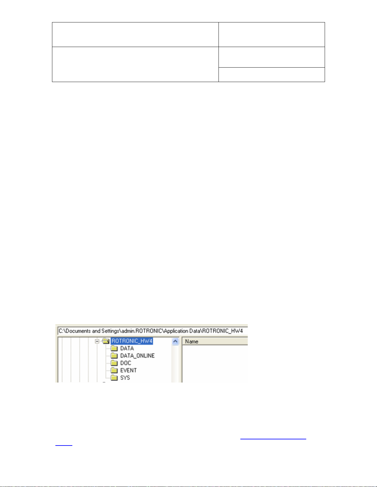
Location of the HW4 User Folder
During the initial startup, HW4 creates a User Folder named ROTRONIC_HW4. By default, this folder is
created in C:\Documents and Settings\Windows User\Application Data, where Windows User is the name
that was used to log into the current Windows session.
This folder is used to hold the HW4 configuration file as well as the different data, event and protocol files
created by HW4.
Windows automatically gives Windows User exclusive access to the directory C:\Documents and
Settings\Windows User and subfolders. For this reason, the default path for the HW4 user folder may not be
suitable for the intended use of HW4.
For instructions about changing the path of the HW4 User Folder, see Relocating the HW4 User
Folder before installing HW4.
© 2008; Rotronic AG E-M-HW4v2-Main_13
Page 14
E-M-HW4v2-Main_13
Rotronic AG
Bassersdorf, Switzerland
Document code
Unit
HW4 software v.2 General instructions and functions
common to all devices
Instruction Manual
Document Type
Page
14 of 165
Document title
Running HW4 from several workstations with a Windows 2003 server
Generally, we do not recommend installing HW4 directly on a Windows 2003 file server. When you wish to
run HW4 on multiple workstations viewing and sharing the same data, you should proceed as follows:
Log in on one of the workstations as an administrator of the Windows 2003 server.
Install HW4 on the workstation following the procedure described under Installing HW4
After installing HW4 and prior to starting HW4, go to the HW4 installation directory on the workstation
and change the path used by HW4 to locate the HW4 User Folder to the root directory of a file
server drive that is mapped on each workstation (see Relocating the HW4 User Folder).
Start HW4 following the procedures described in this manual under Initial Startup
Close HW4 before installing HW4 on the next workstation
Repeat this procedure for each workstation
Note: It is important to distinguish between a Windows workstation user and a HW4 user. It is equally
important to distinguish between the Windows permissions to a folder and HW4 rights. When the HW4 User
Folder is located on the File server and is shared by all workstations, you should give all Windows users
sufficient permissions to the HW4 User Folder and subfolders (Folder Properties - Security).
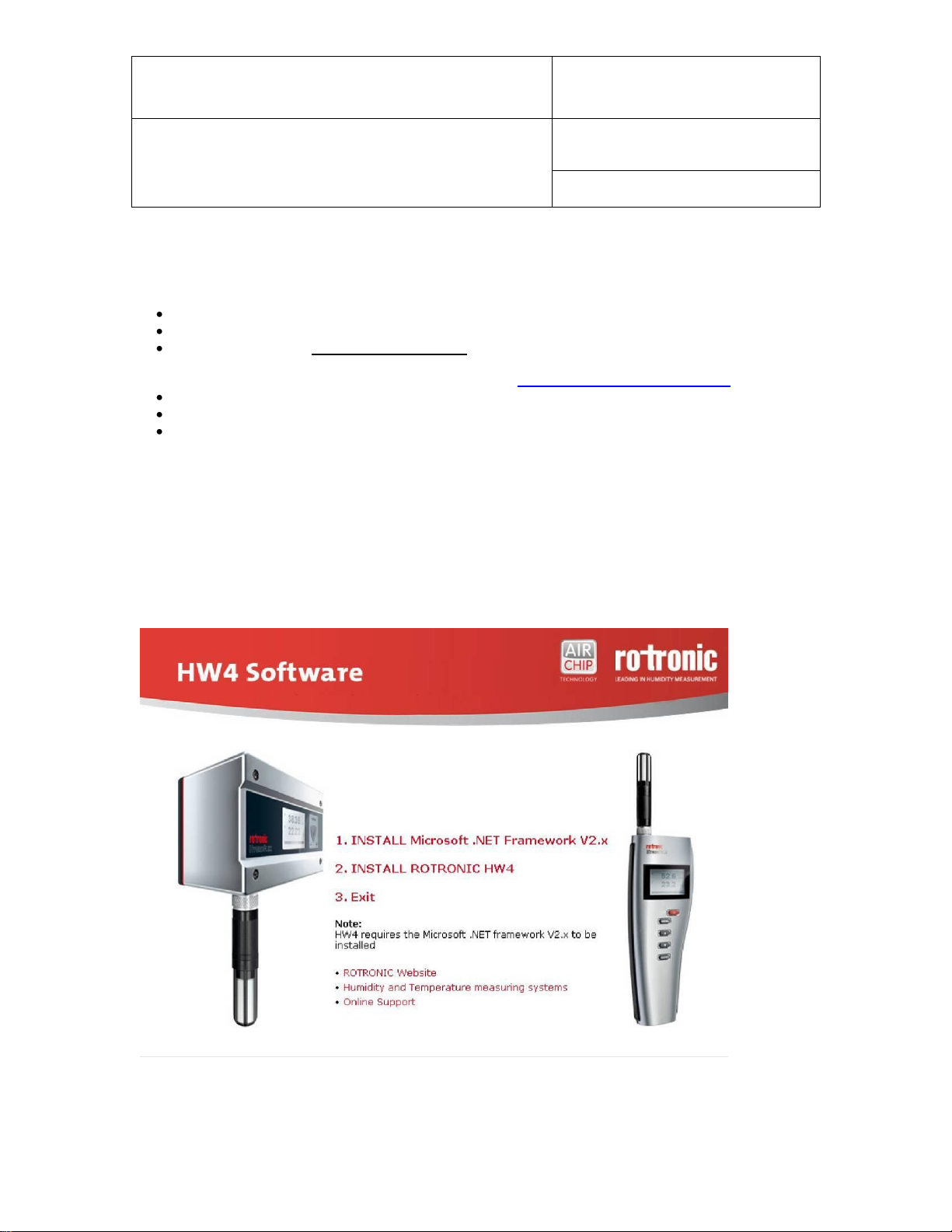
4.3 Installing HW4
Insert the HW4 CD-ROM into the CD drive or your PC. The installation program should start automatically. If
the installation program does not start, use My Computer in Windows to open the CD drive and double click
on the file start.exe located in the root directory of the CD.
© 2008; Rotronic AG E-M-HW4v2-Main_13
Page 15
E-M-HW4v2-Main_13
Rotronic AG
Bassersdorf, Switzerland
Document code
Unit
HW4 software v.2 General instructions and functions
common to all devices
Instruction Manual
Document Type
Page
15 of 165
Document title
IMPORTANT: HW4 requires a PC with the Microsoft .NET Framework version 2.0 or higher installed. If the
Microsoft .NET Framework is not already installed on your PC, please click with the mouse on step 1 to
install the framework.
Note: save your work and close all open files because the computer will have to restart to complete the
installation process.
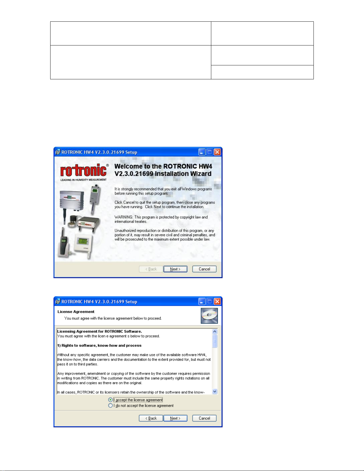
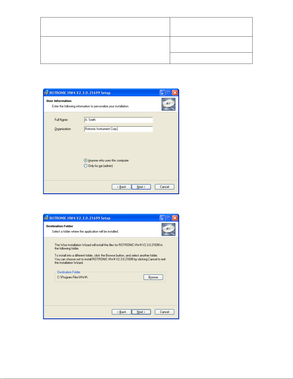
After installing the Microsoft .NET Framework, click on step 2 with the mouse to install HW4. Installation
begins with the following form:
Click on the NEXT button:
© 2008; Rotronic AG E-M-HW4v2-Main_13
Page 16
E-M-HW4v2-Main_13
Rotronic AG
Bassersdorf, Switzerland
Document code
Unit
HW4 software v.2 General instructions and functions
common to all devices
Instruction Manual
Document Type
Page
16 of 165
Document title
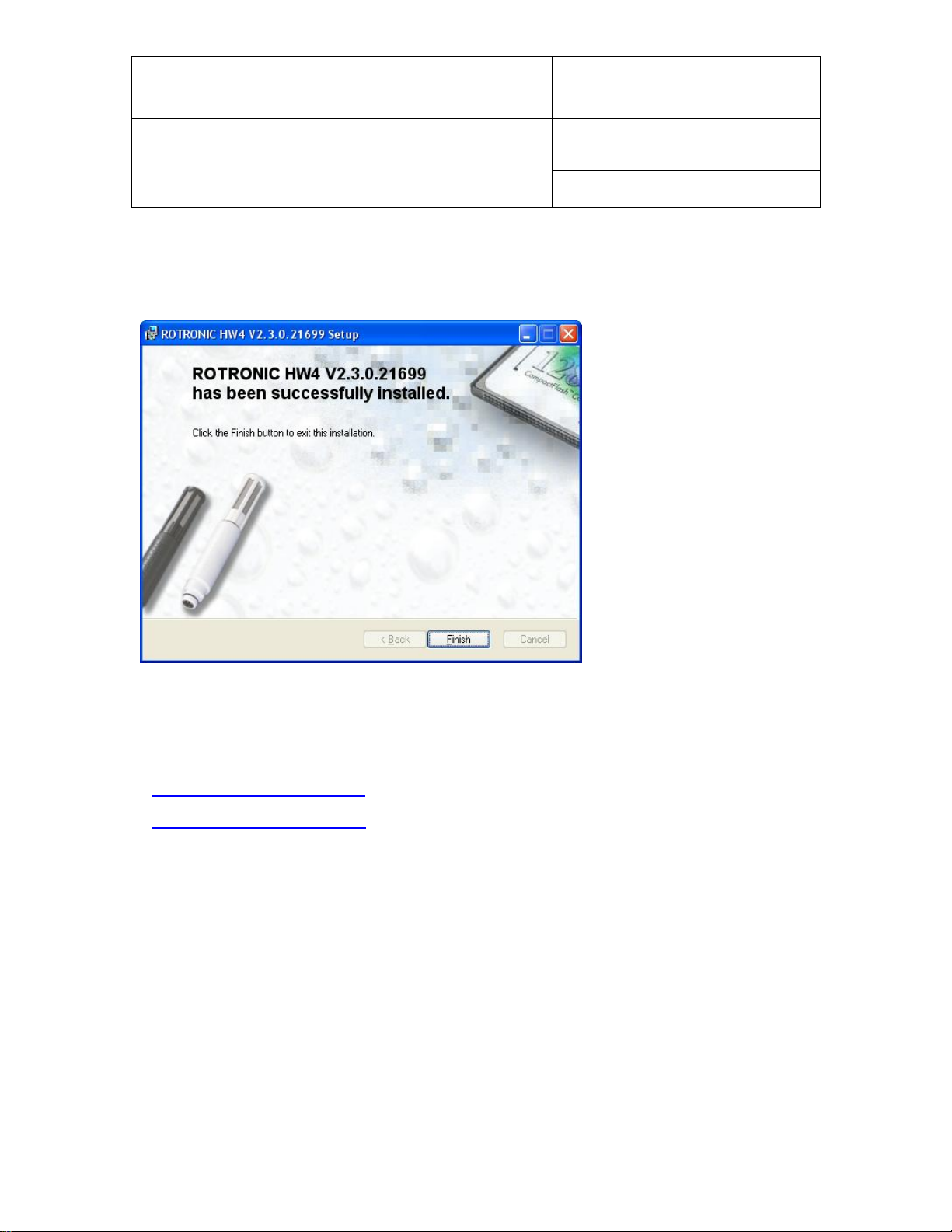
Click on the NEXT button to move through the different installation steps and follow the instructions provided
on the screen.
The choice made above determines how the HW4 install program will make entries in the Windows registry
(entries for all users or for the current user only).
The default installation directory is C:\Program Files\HW4 and can be changed during installation.
The shortcut HW4 is automatically created on the desktop during installation:
© 2008; Rotronic AG E-M-HW4v2-Main_13
Page 17
E-M-HW4v2-Main_13
Rotronic AG
Bassersdorf, Switzerland
Document code
Unit
HW4 software v.2 General instructions and functions
common to all devices
Instruction Manual
Document Type
Page
17 of 165
Document title
Note: Upon starting HW4 for the first time, the folder ROTRONIC_HW4 will be automatically created in
C:\Documents and Settings\Windows User\Application Data, where Windows User is the name that was
used to log into the current Windows session.
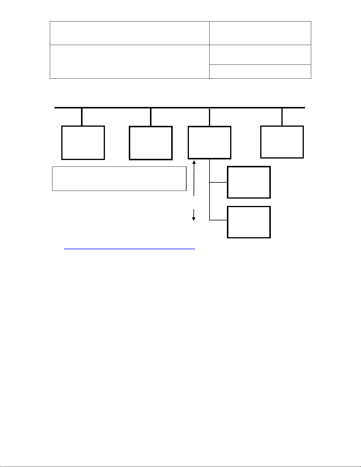
When installation is complete, the following screen should appear:
STOP HERE!
Do not start using HW4 without reading the following:
● Relocating the HW4 User Folder
● Preparing for device connection
© 2008; Rotronic AG E-M-HW4v2-Main_13
Page 18

E-M-HW4v2-Main_13
Rotronic AG
Bassersdorf, Switzerland
Document code
Unit
HW4 software v.2 General instructions and functions
common to all devices
Instruction Manual
Document Type
Page
18 of 165
Document title
4.4 Updating HW4 to a newer version
When updating HW4 to a newer version, two distinct situations may present themselves. In both cases, it is
advisable to make a note of your old HW4 product key prior to updating, even if in principle re-entering this
information and registering the new version of HW4 are not required.
4.4.1 Partial update: HW4.exe
In the case of a partial update, simply copy the new HW4.exe file over the old file, normally located in the
directory C:\Program Files\HW4.
4.4.2 Full update: Install_HW4.exe
In the case of a full update, you should first uninstall the old version of HW4. To do this properly, click on
Start in Windows and open the Control Panel. Select Add or Remove Programs. ROTRONIC HW4 should
be listed as one of the installed programs. Select ROTRONIC HW4 and click on the Remove button.
Note: uninstalling HW4 from the Windows Control Panel does not delete the HW4 User Folder.
IMPORTANT: do not delete the HW4 User Folder (ROTRONIC_HW4) created by the old HW4 version.
Unless otherwise mentioned, this folder can be used with the updated HW4.
The default path of the HW4 User Folder is C:\Documents and Settings\XXXX\Application Data, where
XXXX is the Windows user who initially installed HW4.
Deleting the HW4 User Folder would erase all users, all configuration and measurement data as well as all
event tracking and protocols. It is advisable to make a temporary back-up copy of this folder.
4.5 Uninstalling HW4 (full uninstall)
IMPORTANT: Not following this procedure may result in problems if HW4 is installed again.
To properly uninstall HW4 and remove its main components, you should click on Start in Windows and open
the Control Panel. Select Add or Remove Programs. ROTRONIC HW4 should be listed as one of the
installed programs. Select ROTRONIC HW4 and click on the Remove button.
To complete a full uninstall you should manually delete the HW4 User Folder (ROTRONIC_HW4). The
default path of the HW4 User Folder is C:\Documents and Settings\XXXX\Application Data, where XXXX is
the Windows user who initially installed HW4.
© 2008; Rotronic AG E-M-HW4v2-Main_13
Page 19

E-M-HW4v2-Main_13
Rotronic AG
Bassersdorf, Switzerland
Document code
Unit
HW4 software v.2 General instructions and functions
common to all devices
Instruction Manual
Document Type
Page
19 of 165
Document title
5 CONNECTING DEVICES TO THE HW4 PC
5.1 Definition: masters and slaves (HW4 Professional)
HW4 Professional makes use of the following definitions:
Master: any device / docking station that is directly connected either to a physical or to a virtual port of the
PC or that is directly connected to an Ethernet port (TCP/IP) either by cable or by wireless.
Slave: any device / docking station that is connected to a master by means of an RS-485 multi-drop. Slaves
cannot be used in conjunction with HW4 Standard Edition.
5.2 Connection methods for master devices
All versions of HW4 are compatible with the following methods for connecting devices to the HW4 PC:
● Physical serial port
● Bluetooth serial port (virtual COM port)
● USB port
● LAN (TCP/IP) - cable or wireless connection
5.3 Devices used as RS-485 slaves (HW4 Professional)
HW4 Professional allows the use of one RS-485 multi-drop with each master device. Any RS-485 multi-drop
is limited to a maximum of 64 devices (1 master and up to 63 slaves). Any device with a RS-485 port can be
used either as a master or a slave, without special configuration.
IMPORTANT:
o RS-485 compatibility: the communications protocol used by the products based on the AirChip 3000
technology is not compatible with the protocol used by the previous generation of ROTRONIC products.
Do not connect legacy products and AirChip 3000 products to the same RS-485 multi-drop network.
HW4 is compatible with both AirChip 3000 products and legacy products as long as these products are
connected to separate RS-485 multi-drop network.
o Baud rate: unlike legacy products, the 19200 Baud rate used by all products based on the AirChip
3000 cannot be changed
© 2008; Rotronic AG E-M-HW4v2-Main_13
Page 20
E-M-HW4v2-Main_13
Rotronic AG
Bassersdorf, Switzerland
Document code
Unit
HW4 software v.2 General instructions and functions
common to all devices
Instruction Manual
Document Type
Page
20 of 165
Document title
RS485: 2 wires
PC (HW4)
Network
Interface
Card
RS Addr. 1
RS Addr. 1
RS485
RS485
IP Addr.1
RS Addr. 1
RS485
IP Addr. 2
IP Addr. n
LAN (TCP/IP)
RS-485 multi-drop: up to 1000m (3300 ft)
Note: each device directly connected to the LAN
should have a unique IP address and must meet the
compatibility requirements of the LAN.
RS Addr. 2
RS485
Slave
RS Addr. 64
RS485
Slave
Example: slaves connected to an Ethernet master
See RS-485 slaves: address and Baud rate requirements.
© 2008; Rotronic AG E-M-HW4v2-Main_13
Page 21

E-M-HW4v2-Main_13
Rotronic AG
Bassersdorf, Switzerland
Document code
Unit
HW4 software v.2 General instructions and functions
common to all devices
Instruction Manual
Document Type
Page
21 of 165
Document title
6 PREPARING FOR DEVICE CONNECTION
NOTE:
o The HygroLog NT requires a docking station to provide an interface with the PC.
o If you want to run HW4 on multiple workstations connected to a Windows 2003 file server, use only
devices connected by Ethernet (wired or wireless) because this is the only type of connection that can be
shared by all workstations. Devices connected by RS-485 to an Ethernet device can also be shared.
6.1 Physical serial port
Connecting an instrument or device to a physical COM port of the HW4 PC does not require any
preparation. Simply connect the device to any available serial (COM) port on the PC.
6.2 Bluetooth virtual serial port
Note: This connection method is available only with some HygroLog NT models. Check the local menu of
the HygroLog NT - Settings, and make sure that Bluetooth is on.
Communication via Bluetooth requires the HW4 PC to be equipped with an internal or external Bluetooth
transceiver. Connect your Bluetooth transceiver to the HW4 PC and install the driver supplied with the
transceiver as per the instructions of the transceiver manufacturer.
Typically, the Bluetooth driver has provisions for defining one or several Bluetooth serial ports (look for Local
Services and / or Bluetooth Client Applications). Bluetooth serial ports are virtual COM ports and should be
given a number that is distinct from the physical COM ports already present on the PC. Both the transceiver
attached to the PC and the HygroLog NT should be given a unique COM port number.
In addition, it is usually necessary to “pair” the transceiver with the Bluetooth enabled HygroLog NT. For
security reasons, the process of “pairing” requires a password to be entered. By default, all ROTRONIC
Bluetooth devices are identified as HygroBlue and use 1234 as the pairing password.
In order to allow detection by HW4, any Bluetooth serial port must be manually declared in HW4 Global
Settings – General Tab in the text box labeled Bluetooth serial ports, and then discovered manually using
Search for RS-232 masters under Devices and Groups in the HW4 main menu bar.
HW4 detects and displays a Bluetooth device in the same manner as any device connected to the PC by
way of a physical serial port.
6.3 USB port
Prior to connecting any ROTRONIC device to a USB port you should install the ROTRONIC USB driver on
the HW4 PC.
IMPORTANT: do not run HW4 while installing the USB driver on the PC.
The ROTRONIC USB driver (ROTRONIC USB Option) can be installed before or after installing HW4.
The following example shows how to install the driver with Windows XP.
1. Prior to connecting the device to the PC, insert the HW4 CD-ROM in any available PC drive. The HW4
installation screen starts automatically. Exit this screen.
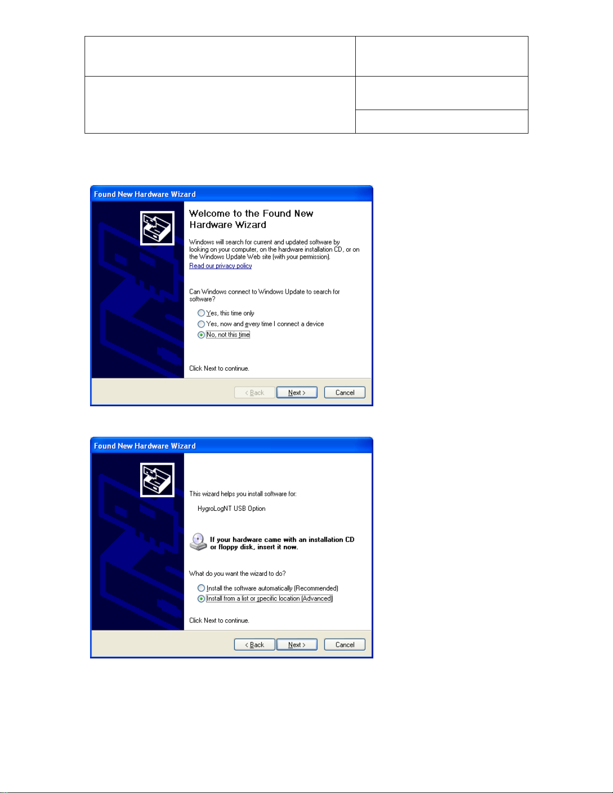
2. Connect the instrument or docking station to any available USB port. Upon detecting the presence of a
device connected to the USB port, Windows XP automatically starts the following wizard:
© 2008; Rotronic AG E-M-HW4v2-Main_13
Page 22
E-M-HW4v2-Main_13
Rotronic AG
Bassersdorf, Switzerland
Document code
Unit
HW4 software v.2 General instructions and functions
common to all devices
Instruction Manual
Document Type
Page
22 of 165
Document title
If you are using Windows XP Professional SP2, the following screen appears. Select “No, not this time” and
click on Next. This screen does not appear if you have not installed SP2.
3. The following screen appears:
Select “Install from a list or specific location” and click on Next.
© 2008; Rotronic AG E-M-HW4v2-Main_13
Page 23
E-M-HW4v2-Main_13
Rotronic AG
Bassersdorf, Switzerland
Document code
Unit
HW4 software v.2 General instructions and functions
common to all devices
Instruction Manual
Document Type
Page
23 of 165
Document title
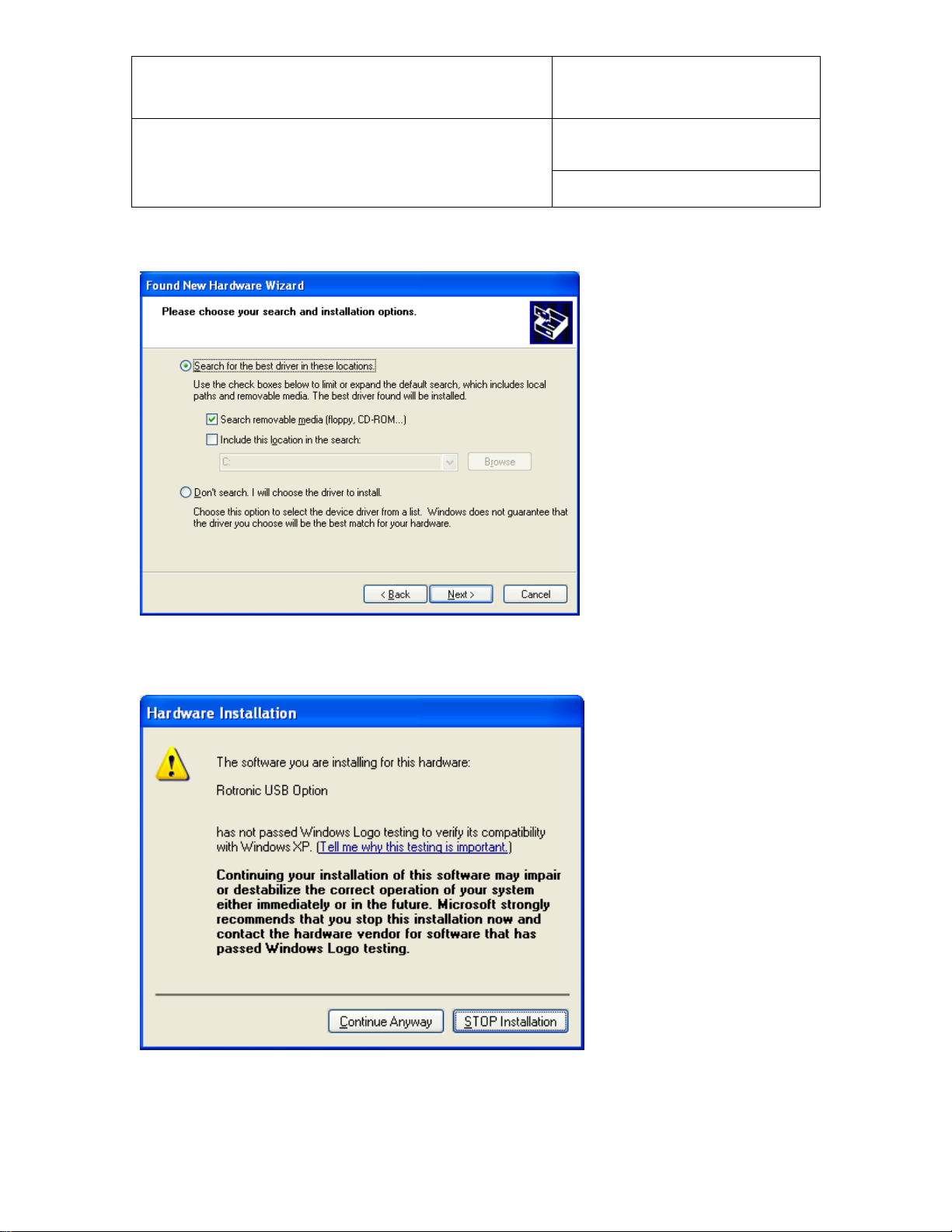
4. Select “Search for the best driver in these locations”. Note that at this time the HW4 CD_ROM should
have been already inserted in the PC.
Click on Next
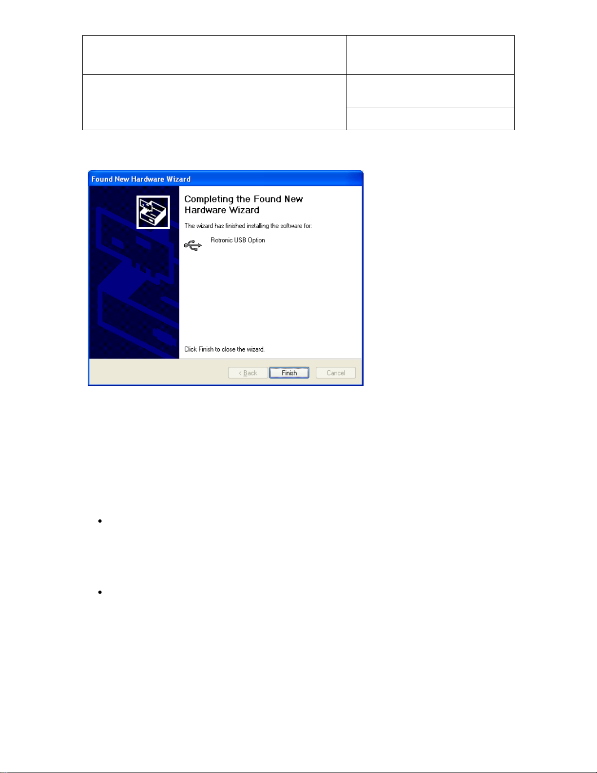
5. You will receive the following warning. Disregard this warning and click on “Continue anyway”.
© 2008; Rotronic AG E-M-HW4v2-Main_13
Page 24
E-M-HW4v2-Main_13
Rotronic AG
Bassersdorf, Switzerland
Document code
Unit
HW4 software v.2 General instructions and functions
common to all devices
Instruction Manual
Document Type
Page
24 of 165
Document title
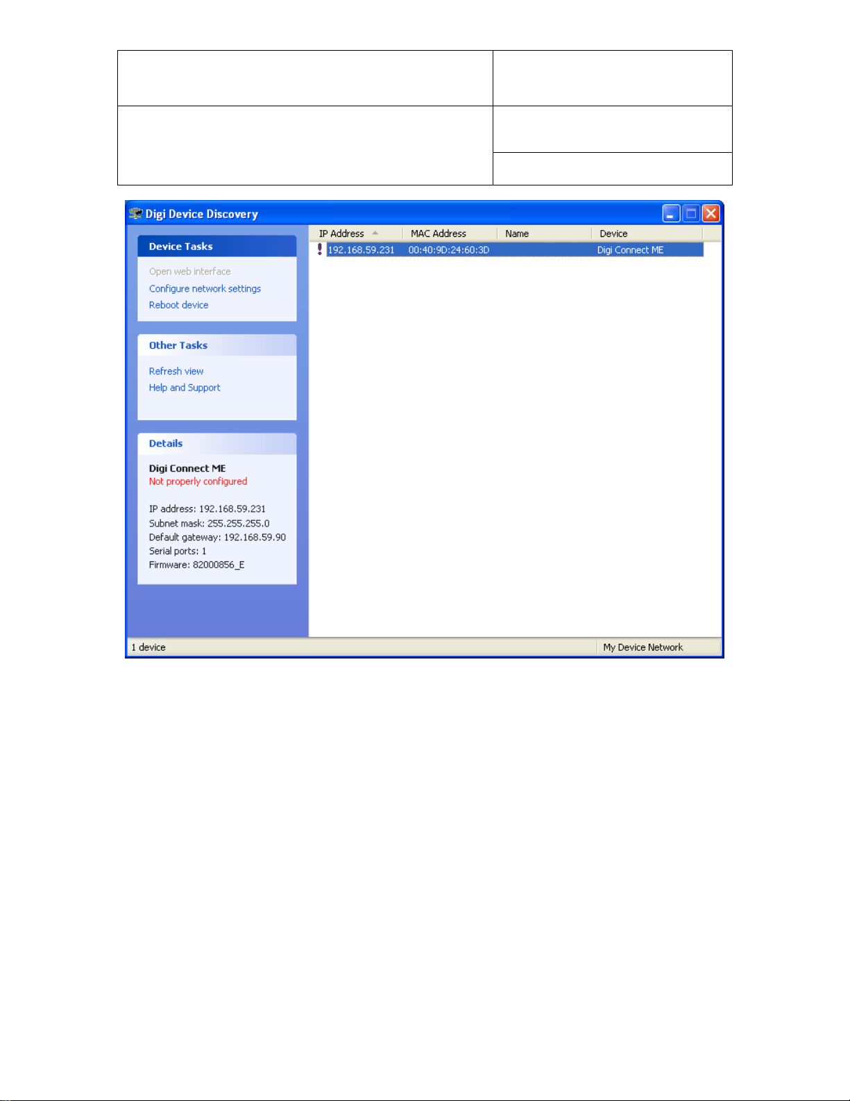
6. Windows copies the USB driver located on the HW4 CD-ROM and displays the following message when
done:
Click on “Finish” to complete the process.
Note: If your device has only a serial port and the PC has a USB port but no COM port, you can install a
USB Serial Adapter on one of the PC USB ports. In this situation, install the driver supplied with the USB
serial adapter (not the driver supplied with HW4) and connect the device to this adapter. HW4 will assume
that the device is connected to a serial (COM) port.
6.4 Ethernet (TCP/IP) connection
NOTES:
ROTRONIC devices with an Ethernet interface require configuration of the TCP/IP settings to ensure
compatibility with the LAN to which the HW4 PC is connected (IP address, sub-net mask, gateway,
etc.). Detailed instructions for configuring a ROTRONIC device with Ethernet (TCP/IP) interface are
provided separately in document IN-E-TCPIP-Conf_11. A PDF version of this document can be
downloaded from our web site. You may also want to read “Basic TCP/IP concepts” in this manual
or consult with your network administrator prior to connecting any device to your local area network.
ROTRONIC devices with an Ethernet interface (both wired and wireless) are shipped with a Device
Configuration Certificate that provides information about the factory configuration settings of both the
Ethernet module and device.
© 2008; Rotronic AG E-M-HW4v2-Main_13
Page 25

E-M-HW4v2-Main_13
Rotronic AG
Bassersdorf, Switzerland
Document code
Unit
HW4 software v.2 General instructions and functions
common to all devices
Instruction Manual
Document Type
Page
25 of 165
Document title
Before configuring the device TCP/IP settings, you should make sure that the following is available to you:
o An unused static IP address that is compatible with your network
o The subnet mask of your network
o The local IP address of the router used on the same LAN as the HW4 PC, the default gateway used by
all devices on the LAN
In addition, the following information is required for a wireless connection:
o The wireless network name (SSID)
o The security mode (WAP, WEP or other) used by the HW4 network and the key or keys used by the
security mode.
6.4.1 Wired TCP/IP connection
A device discovery utility (Digi Device Discovery) is provided in the HW4 installation directory (usually,
C:\Program Files\HW4). The name of the corresponding file is dgdiscvr.exe. The Digi Device Discovery
utility can be started by double clicking with the mouse on the file.
Digi Device Discovery detects only products from Digi International such as the internal Ethernet module
currently used by ROTRONIC for devices with an Ethernet interface.
Connect the device to be configured to your LAN and double click with the mouse on dgdiscvr.exe to start
Digi Device Discovery.
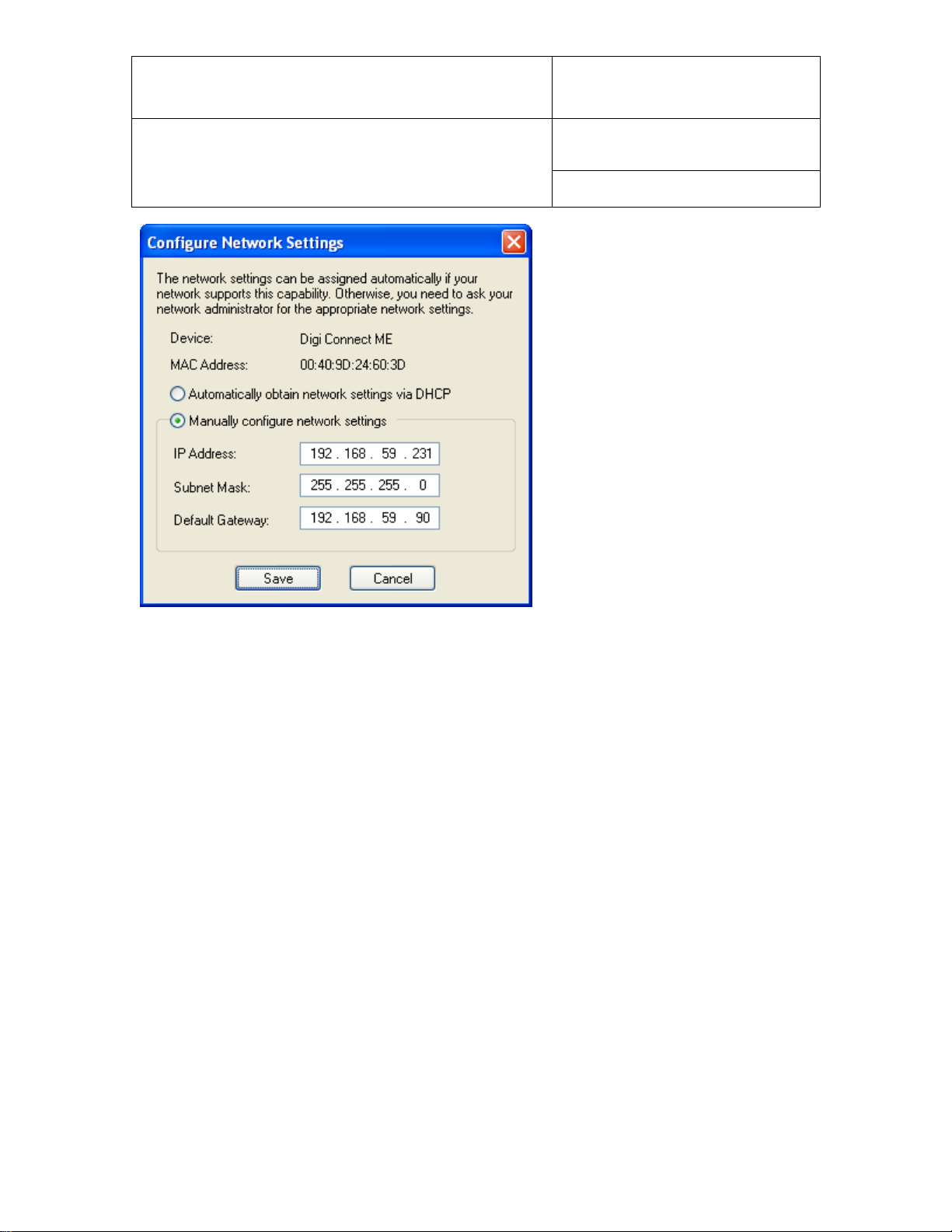
When activated, Digi Device Discovery automatically detects any ROTRONIC device present on the LAN
and provides a list of all such devices.
The following example shows the initial screen for a device with TCP/IP settings that are not compatible with
the LAN. Note the red warning that appears on the left side of the screen when the device is selected
(highlighted).
© 2008; Rotronic AG E-M-HW4v2-Main_13
Page 26
E-M-HW4v2-Main_13
Rotronic AG
Bassersdorf, Switzerland
Document code
Unit
HW4 software v.2 General instructions and functions
common to all devices
Instruction Manual
Document Type
Page
26 of 165
Document title
With the device highlighted, click on “Configure network settings” to open the dialog box shown below.
© 2008; Rotronic AG E-M-HW4v2-Main_13
Page 27
E-M-HW4v2-Main_13
Rotronic AG
Bassersdorf, Switzerland
Document code
Unit
HW4 software v.2 General instructions and functions
common to all devices
Instruction Manual
Document Type
Page
27 of 165
Document title
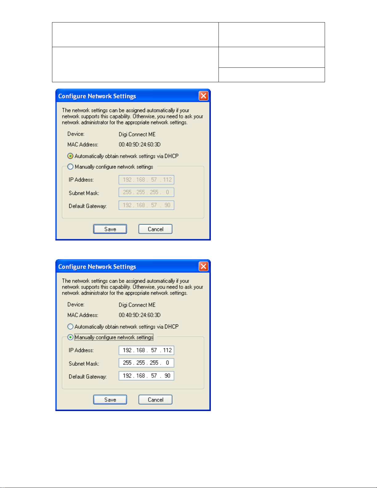
When in doubt as to which setting to enter manually, select “automatically obtain network settings via
DHCP” (requires a LAN with DHCP server such as a router). Using DHCP ensures that the device settings
that are compatible with the LAN (subnet mask and default gateway) and that the IP address does not
generate any conflict.
Click on Save, Reboot the device and click on Refresh View.
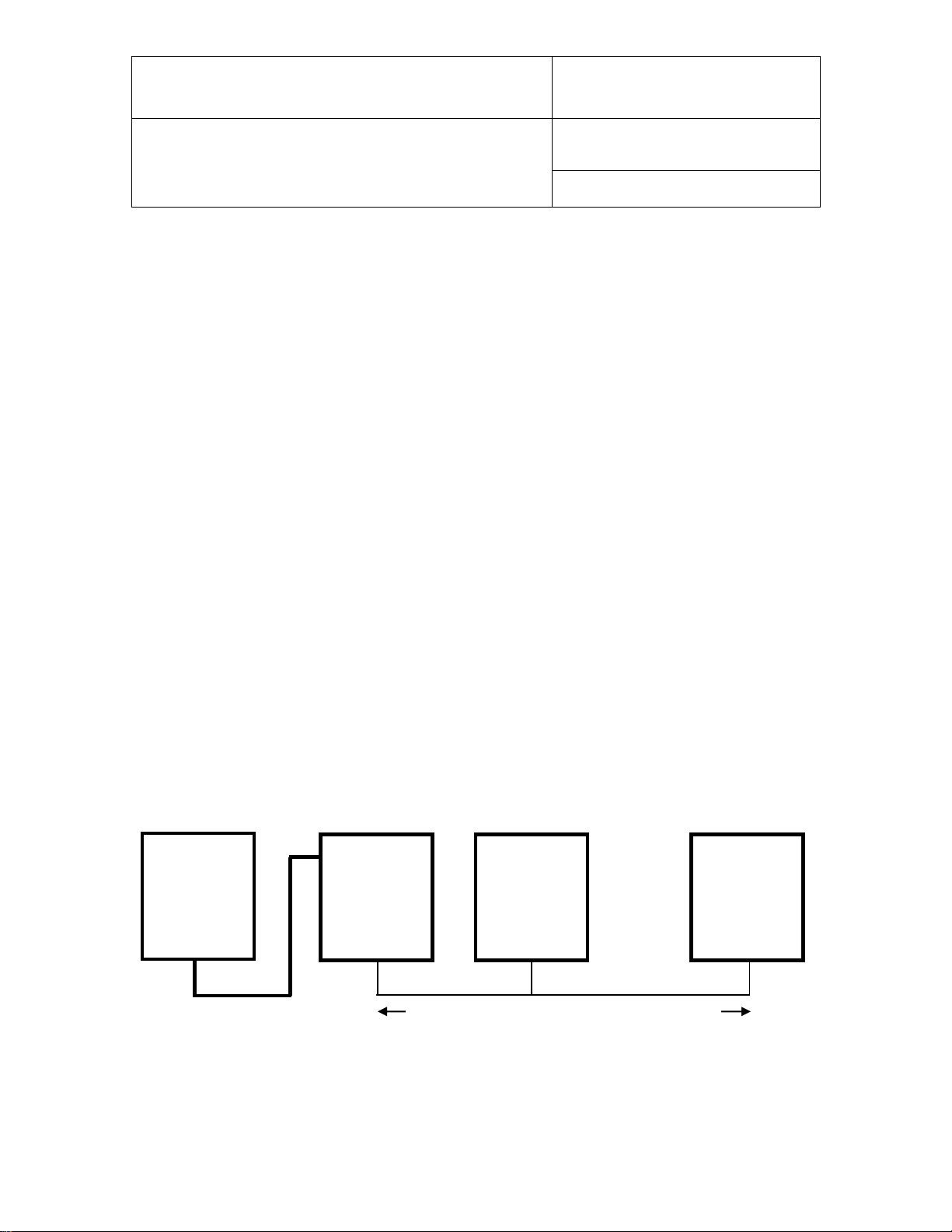
A dynamic IP address is subject to change whenever the device is powered down and then powered up. For
this reason, you should now change the device configuration from dynamic IP address (DHCP) to static IP
address. To do this, click again on “Configure network settings”. The current settings of the device (IP
address, subnet mask, etc.) appear in light gray.
© 2008; Rotronic AG E-M-HW4v2-Main_13
Page 28
E-M-HW4v2-Main_13
Rotronic AG
Bassersdorf, Switzerland
Document code
Unit
HW4 software v.2 General instructions and functions
common to all devices
Instruction Manual
Document Type
Page
28 of 165
Document title
Click on “Manually configure network settings”.
Change the device IP address to an address that is both currently unused on the LAN and outside of the
range of dynamic IP addresses used by the DHCP server. To select a proper address, you may want to
consult your network administrator.
© 2008; Rotronic AG E-M-HW4v2-Main_13
Page 29
E-M-HW4v2-Main_13
Rotronic AG
Bassersdorf, Switzerland
Document code
Unit
HW4 software v.2 General instructions and functions
common to all devices
Instruction Manual
Document Type
Page
29 of 165
Document title
RS232: 3 wires (including ground wire)
RS485: 2 wires
PC (HW4)
COM Port
or
USB port
Address 1
Address 2
Address 64
RS232 or
USB
RS485
RS485
RS485
up to 150m (490 ft)
Slave
Slave
RS-485 multi-drop: up to 1000m (3300 ft)
HW4 Professional only
6.4.2 Wireless TCP/IP connection
The internal Digi module WI-ME used by wireless ROTRONIC devices does not allow a wired connection to
a LAN and must be configured using a wireless connection.
To allow a new wireless device to connect, the HW4 network wireless router has to be temporarily
reconfigured and the wireless network security disabled. This is clearly not practical for most users and we
recommend using a dedicated wireless router for the purpose of configuring a wireless ROTRONIC device.
Detailed instructions for configuring a wireless Ethernet ROTRONIC device are provided separately in
document IN-E-TCPIP-Conf_11. A PDF version of this document can be downloaded from our web site.
6.5 RS-485 slaves: address and Baud rate requirements
IMPORTANT:
o RS-485 compatibility: The communications protocol used by the products based on the AirChip 3000
technology is not compatible with the protocol used by the previous generation of ROTRONIC products.
Do not connect legacy products and AirChip 3000 products to the same RS-485 multi-drop network.
o Baud rate: the 19200 Baud rate used by all products based on the AirChip 3000 cannot be changed
All devices that are compatible with HW4 have an internal RS-485 address ranging from 0 to 64. The factory
default for the RS-485 address is 0. Similarly, devices are configured at the factory to use a specific Baud
rate for all serial communications. In the case of devices with an internal Ethernet (TCP/IP) module, serial
communication includes communication between the device proper and it internal Ethernet module.
The RS-485 address is part of the communications protocol used by HW4 and is always included in the
command sent to a device and in the device response. In the case of an RS-485 multi-drop, this address is
used to identify each device and should be unique within the same multi-drop.
Example: slaves connected to a COM or USB master
© 2008; Rotronic AG E-M-HW4v2-Main_13
Page 30

E-M-HW4v2-Main_13
Rotronic AG
Bassersdorf, Switzerland
Document code
Unit
HW4 software v.2 General instructions and functions
common to all devices
Instruction Manual
Document Type
Page
30 of 165
Document title
When searching for RS-485 slaves, HW4 automatically changes the factory default RS-address of both
masters and slaves as explained below:
o Masters: HW4 automatically changes the RS-485 address of any new device that is directly connected
to the PC (master) from 0 to 1. As a result, all masters discovered by HW4 end up having the same RS485 network address (1).
o Slaves: in the situation where an RS-485 multi-drop is detected during a search, HW4 automatically
changes the address of each slave with address 0 to a unique address ranging from 2 to 64. The same
address range (2 to 64) is used again when there is more than one RS-485 multi-drop.
IMPORTANT:
o Avoid changing manually the factory default RS address (0) of new devices. Allow HW4 to change this
address automatically.
o Change manually the RS address to 0 in the following situations:
- A master will now be used as a slave
- A slave is being moved from one multi-drop to another.
The change of address should be done prior to changing the physical connection (use HW4 Device
Manager). If you forgot to do this, temporarily connect the device as a master to do the address change.
o Duplicate RS addresses are not permitted within the same RS-485 multi-drop (with the exception of
temporary address 0). Duplicate addresses may prevent communication with the devices or give
unpredictable results. It is OK to use the same RS address in different multi-drops.
o All devices within a multi-drop must use the same baud rate. Different Baud rates will prevent
communication between the devices and the HW4 PC.
Master with Ethernet (TCP/IP) interface: any change to Baud rate of the device done with HW4 Device
Manager should also be reflected in the configuration of the internal Digi International module used by
the device to connect to the LAN.
See: Changing the baud rate of an Ethernet device
© 2008; Rotronic AG E-M-HW4v2-Main_13
Page 31

E-M-HW4v2-Main_13
Rotronic AG
Bassersdorf, Switzerland
Document code
Unit
HW4 software v.2 General instructions and functions
common to all devices
Instruction Manual
Document Type
Page
31 of 165
Document title
7 INITIAL START-UP
Click on the HW4 shortcut created on your desktop by the installation program.
7.1 Language selection
The first form to open lists the different language files available within HW4:
Use the mouse to highlight the desired language and click on Open.
© 2008; Rotronic AG E-M-HW4v2-Main_13
Page 32

E-M-HW4v2-Main_13
Rotronic AG
Bassersdorf, Switzerland
Document code
Unit
HW4 software v.2 General instructions and functions
common to all devices
Instruction Manual
Document Type
Page
32 of 165
Document title
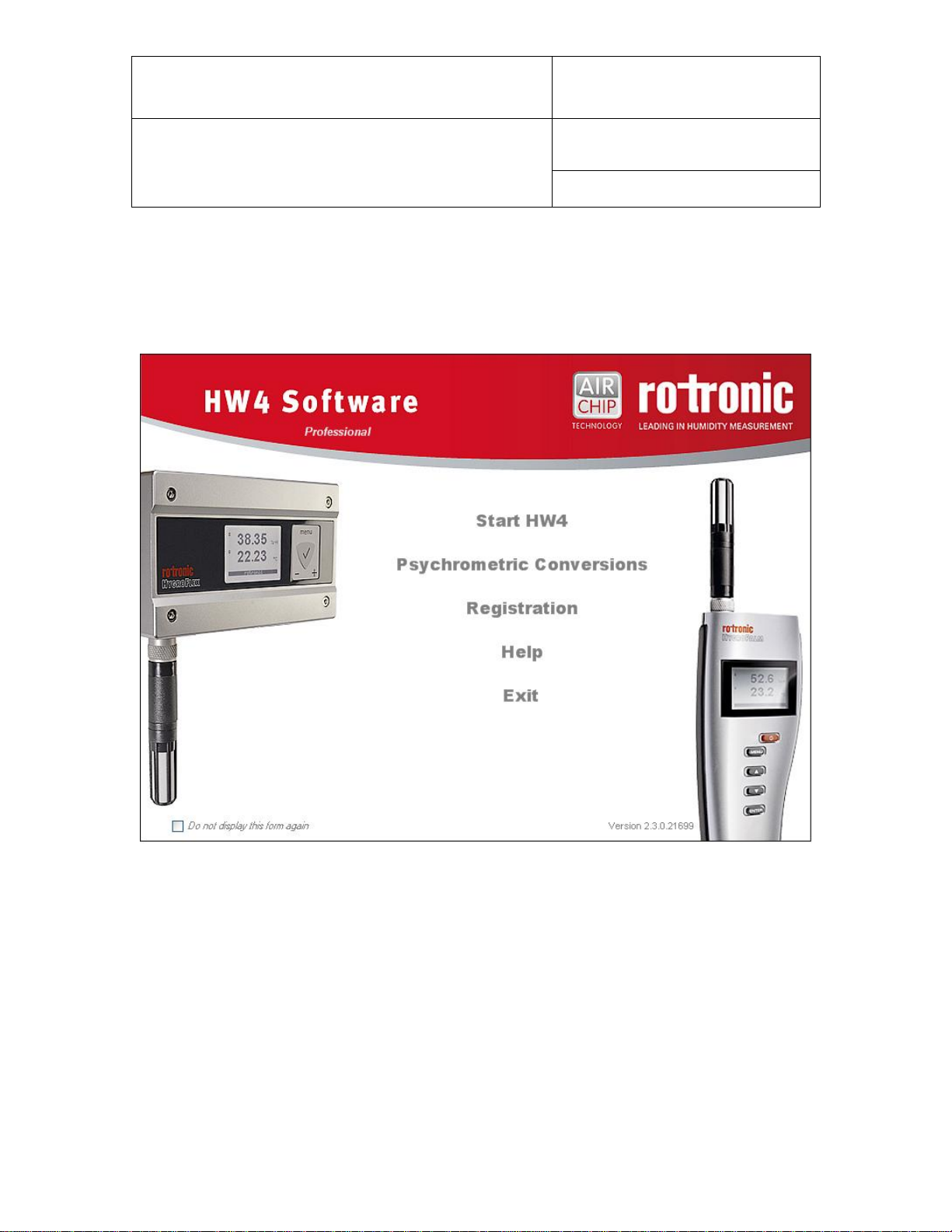
7.2 Product key and registration
The next form is the HW4 start-up form:
First Time Users: HW4 requires you to register and you should now click with the mouse on the underlined
Registration link. This opens the following form:
© 2008; Rotronic AG E-M-HW4v2-Main_13
Page 33

E-M-HW4v2-Main_13
Rotronic AG
Bassersdorf, Switzerland
Document code
Unit
HW4 software v.2 General instructions and functions
common to all devices
Instruction Manual
Document Type
Page
33 of 165
Document title
Enter the HW4 product key, which is printed on a sticker affixed to the protective cover of the HW4 CD. Fill
in the required information. If the box Register on-line is checked, clicking on Continue will connect you to
the ROTRONIC web site, where your registration data will be automatically entered. If you do not have an
internet connection or if you have already registered your copy of HW4, uncheck the Register on-line box
and click on Continue.
Registering on-line offers benefits such as free updates / patches and product information.
Upon completing the registration, HW4 returns to the Start-up Screen. Depending on the HW4 product key
entered in the previous form, the edition of HW4 that you are using is shown on the screen (in the example
below: the validated edition of HW4 Professional).
© 2008; Rotronic AG E-M-HW4v2-Main_13
Page 34

E-M-HW4v2-Main_13
Rotronic AG
Bassersdorf, Switzerland
Document code
Unit
HW4 software v.2 General instructions and functions
common to all devices
Instruction Manual
Document Type
Page
34 of 165
Document title
To open the HW4 main screen, click with the mouse on the blue link labeled Start HW4.
7.3 Automatic device discovery during initial start-up
During the initial start-up, HW4 automatically searches for any device that is connected either to a COM port
or to a USB port of the PC. HW4 stops searching after finding one such device. Devices connected by any
other method must be searched manually.
IMPORTANT: see also the following
Preparing for device connection
Searching for devices with HW4
© 2008; Rotronic AG E-M-HW4v2-Main_13
Page 35

E-M-HW4v2-Main_13
Rotronic AG
Bassersdorf, Switzerland
Document code
Unit
HW4 software v.2 General instructions and functions
common to all devices
Instruction Manual
Document Type
Page
35 of 165
Document title
When there is no device connected to the PC either by a COM port or by a USB port, HW4 stops searching
after a single pass. In that situation, HW4 creates a fictitious HygroLog NT in the device tree (see “HW4
main screen overview”). This instrument is named “Offline” and should be deleted after manually
discovering the actual devices connected to the PC. The red cross on top of the device icon indicates that
there is no communication with the device.
Note: whenever the device tree is empty HW4 automatically does the same search as during the initial startup.
7.4 Creating the first user (HW4 Professional)
If you are using HW4 Professional, you should create at least one user with administrator rights and a
password in order to comply with ERES regulatory requirements.
See: Users and passwords.
Once the first user has been created, you will need to log in each time that you open HW4.
7.5 Access to functions and screens (HW4 Professional)
In all versions of HW4 Professional, access to most functions and screen views requires the current user to
have sufficient rights. Whenever a function is not accessible or a screen view is not available, please verify
that you have been granted the necessary rights.
For an overview of user rights, including details for each individual right, please refer to the chapter Users
and Passwords.
© 2008; Rotronic AG E-M-HW4v2-Main_13
Page 36

E-M-HW4v2-Main_13
Rotronic AG
Bassersdorf, Switzerland
Document code
Unit
HW4 software v.2 General instructions and functions
common to all devices
Instruction Manual
Document Type
Page
36 of 165
Document title
8 SEARCHING FOR DEVICES WITH HW4
IMPORTANT:
The following instructions assume that all necessary preparations have been made prior to connecting the
different devices to the HW4 PC. See Preparing for device connection.
8.1 Searching for master devices
Depending on the connection method used for the master, use the following commands available in the
HW4 main menu bar under Devices and Groups:
o Physical COM (serial) port : Search for RS-232 masters
o Bluetooth virtual COM port : Search for RS-232 masters
o USB port : Search for USB masters
o Ethernet (TCP/IP) - cable or wireless connection : Search for Ethernet masters
: Search for Specific IP Address
Search for Ethernet masters: this command searches only for devices that are directly connected to the
same local area network as the HW4 PC (both cable and wireless connection). The IP address of the
device(s) does not have to be specified by the user.
When the TCP/IP settings of a device are not compatible with the local area network, HW4 displays the
following message box:
Search for Specific IP Address: use this command to search for Ethernet devices that are connected to a
different network (eventually via Internet). The IP address of the device must be specified by the user.
8.2 Searching for RS-485 slaves (HW4 Professional)
Use the Search for RS-485 slave devices command located in the HW4 main menu bar under Devices
and Groups.
© 2008; Rotronic AG E-M-HW4v2-Main_13
Page 37

E-M-HW4v2-Main_13
Rotronic AG
Bassersdorf, Switzerland
Document code
Unit
HW4 software v.2 General instructions and functions
common to all devices
Instruction Manual
Document Type
Page
37 of 165
Document title
Left
Pane
Right
Pane
9 HW4 MAIN SCREEN
The HW4 main screen varies slightly depending on which edition of HW4 is running. The following
description applies to the Professional edition which has more menu items and screens than the standard
edition.
The HW4 main screen is subdivided into a left pane and a right pane. The width of each pane can be
adjusted with the mouse. The height of the two sub-panes located in the right pane (table and graph) can
also be adjusted with the mouse. To change the size of a pane, go over the separation line with the mouse
cursor. When the cursor changes, click and hold with the mouse. Drag the separation line where you want it
to be.
© 2008; Rotronic AG E-M-HW4v2-Main_13
Page 38

E-M-HW4v2-Main_13
Rotronic AG
Bassersdorf, Switzerland
Document code
Unit
HW4 software v.2 General instructions and functions
common to all devices
Instruction Manual
Document Type
Page
38 of 165
Document title
Each individual device is displayed in the left
pane (for example: Master HCA, HCA Test,
etc.). This is the default view for all versions of
HW4 and the only view available with HW4
Standard edition
Functions available for each device can be seen
when the tree is expanded. These functions are
specific of each type of device.
To select a device or a function, click on it with
the left mouse button.
9.1 Device Tree (left pane)
9.1.1 Tree populated with individual devices
All versions of HW4 display on the left pane of the screen a tree listing the devices that have been
discovered by HW4.
Right clicking with the mouse on a device opens the following menu:
Most items present in this menu are
described in chapter 10: HW4 Main Menu
Bar, under Device and Groups and under
View.
The following menu items are present only in
the case of a master device:
o Search for RS-485 Slave Devices
o Refresh the RS-485 Slave Devices
Search adds to the device tree any device
connected to the RS-485 interface of the
master
Refresh does not add nay new devices and
is used to re-establish a lost connection with
slave devices already present in the tree.
© 2008; Rotronic AG E-M-HW4v2-Main_13
Page 39

E-M-HW4v2-Main_13
Rotronic AG
Bassersdorf, Switzerland
Document code
Unit
HW4 software v.2 General instructions and functions
common to all devices
Instruction Manual
Document Type
Page
39 of 165
Document title
HW4 Professional edition allows the creation of
device groups. When one or more groups have
been created (example JPL PC, RIC LAN and RIC
Wireless), and all devices have been moved to a
group, the left pane displays a tree listing only
groups.
A group can be expanded to show the devices
within the group and each device can be expanded
to show its functions.
To select a group, a device or a function, click on it
with the left mouse button.
The left pane can also display one or several
device groups (JPL PC, RIC LAN and RIC
Wireless) as well as individual devices that are
not part of any group (HygroStat MB, RTD Test).
9.1.2 Tree populated with device group(s) - HW4 Professional
A device group is a logical grouping of devices (as opposed to a physical grouping) created and defined by
the user. Both masters and slaves can be part of a group, with no restriction other than not duplicating
devices. Individual devices can be moved to any existing group or removed from the group (see “Devices
and Groups”).
In addition to facilitating network management within HW4, using device groups makes it possible to
simultaneously display selected data from several individual devices within a group. The data can be viewed
either as a table or as a live graph.
By default HW4 displays a device group as opposed to displaying each individual device in the group.
Individual devices can be displayed by expanding the group.
Note: after being detected, devices appear individually in the tree regardless of the manner in which they are
connected to the PC (master or slave).
© 2008; Rotronic AG E-M-HW4v2-Main_13
Page 40

E-M-HW4v2-Main_13
Rotronic AG
Bassersdorf, Switzerland
Document code
Unit
HW4 software v.2 General instructions and functions
common to all devices
Instruction Manual
Document Type
Page
40 of 165
Document title
9.1.3 Instrument group: renaming and changing the contents
The following menu can be opened by right clicking on a group:
Rename Group: after creating a group, the group can be renamed in the same manner as a file can be
renamed in Windows.
► Add a device to a group:
After creating a group, individual devices can be moved to the group. Click on the device with the mouse
and hold. A small rectangle appears next to the device. Drag the small rectangle on top of the group.
Release the mouse when the name of the group is highlighted. Instruments within a group are displayed in
the reverse order in which they were added to the group.
► Remove a device from a group:
Expand the group to display all devices within the group. Click on the device with the mouse and hold. A
small rectangle appears next to the device. Drag the small rectangle to the bottom of the device tree, clear
of any group and release the mouse.
© 2008; Rotronic AG E-M-HW4v2-Main_13
Page 41

E-M-HW4v2-Main_13
Rotronic AG
Bassersdorf, Switzerland
Document code
Unit
HW4 software v.2 General instructions and functions
common to all devices
Instruction Manual
Document Type
Page
41 of 165
Document title
9.2 Right pane in Device View mode
The right pane is in the Device View mode whenever an individual device is selected in the device tree (left
pane).
In the Device View mode, the right pane is as illustrated below. To select any of the available tabs, click on
the corresponding label with the mouse left button.
© 2008; Rotronic AG E-M-HW4v2-Main_13
Page 42

E-M-HW4v2-Main_13
Rotronic AG
Bassersdorf, Switzerland
Document code
Unit
HW4 software v.2 General instructions and functions
common to all devices
Instruction Manual
Document Type
Page
42 of 165
Document title
Data
Column Headers
Notes
Humidity digital
Humidity
Value 1
HygroClip probe digital output
Humidity analog
Value 1
HygroClip probe analog output
(channel 1)
Temperature digital
Temperature
Value 2
HygroClip probe digital output
Temperature analog
N/A
Our instruments accept only single channel
analog probes (channel 1 = humidity)
Calculation
Calculation
Dew point, humidity ratio, etc.
Analog probe (single channel)
Analog Input
Value 1
3d party analog probe
Pressure probe
Analog Input
Value 1
3d party analog pressure probe
Custom Calculation
Custom Calc.
Value 1
Requires an instrument that can be configured
to perform a user defined calculation such as
the difference between two temperatures.
Logical input 1
L-Input 1
Value 1
Logical input used to monitor an external
contact (1 = closed / 0 = open)
Logical input 2
L-Input 2
Value 2
Logical input used to monitor an external
contact (1 = closed / 0 = open)
9.2.1 Current Values tab
With this tab selected, the top of the right pane displays a table of the most recent values for the device
currently selected in the device tree. The values are continuously updated according to the device polling
interval set in HW4 Global Settings > General tab.
The table shows data from the different probe inputs of the device, as well as other information. Click and
drag a column header with the mouse to change in which order fields are being displayed.
The table displayed in the Current Values tab can be customized.
9.2.1.1 Customizing the Current Values tab
► Data columns in the Current Values tab
Depending both on the type of device and on the configuration of the device, HW4 can display a number of
data elements in the Current Values tab. Different types of data appear in different columns of the Current
Values table as explained below:
© 2008; Rotronic AG E-M-HW4v2-Main_13
Page 43

E-M-HW4v2-Main_13
Rotronic AG
Bassersdorf, Switzerland
Document code
Unit
HW4 software v.2 General instructions and functions
common to all devices
Instruction Manual
Document Type
Page
43 of 165
Document title
Data
Column Headers
Notes
Relay 1 to Relay 4
Relays
Value 1
Status of relay outputs 1 to 4
(1 = energized / 0 = de-energized)
Note: the columns “Value 1” and “Value 2” are provided for users who wish to minimize the number of
columns in the data table.
► Column selection in the Current Values tab
To make HW4 display only specific data columns in the Current Values tab, select any individual device
present in the device tree (for example HyGen Lab 2 in the left pane). In the HW4 main menu bar, click on
Settings and Tools and on Column Headers.
HW4 opens the following form. Make your selection using the mouse. The selection applies globally to all
devices displayed in the Current Values tab.
© 2008; Rotronic AG E-M-HW4v2-Main_13
Page 44

E-M-HW4v2-Main_13
Rotronic AG
Bassersdorf, Switzerland
Document code
Unit
HW4 software v.2 General instructions and functions
common to all devices
Instruction Manual
Document Type
Page
44 of 165
Document title
► Order of the columns in the Current Values tab
The order of the columns in the Current Values tab can be changed. To move a column to the right or to the
left, left click with the mouse on the column header and drag it to its new position.
► Row selection in the Current Values tab
Select a device present in the device tree and use View Tab to select the rows to be displayed in the
Current Values tab. The row selection applies only to the device currently selected in the device tree.
NOTES:
o The selections made in the View Tab affect the Current Values Tab in the Group View mode.
o The selections made in the View Tab also affect the following tabs and forms: On-line buffer tab, Log to
PC tab, Device Manager form, Data Logging form and Probe Adjustment form.
If you do not see an input, a contact, etc. in any of these tabs and forms, remember to check the
selections made in the View Tab.
© 2008; Rotronic AG E-M-HW4v2-Main_13
Page 45

E-M-HW4v2-Main_13
Rotronic AG
Bassersdorf, Switzerland
Document code
Unit
HW4 software v.2 General instructions and functions
common to all devices
Instruction Manual
Document Type
Page
45 of 165
Document title
The following selections can be made with the mouse:
on the desired probe number in the table located above the
graph.
desired parameter in the table.
header of the parameter.
If so desired, the graph can be hidden so as to provide more
room for the probe data table (see HW4 Global Settings - View
Tab).
9.2.2 Online graph
By default, the bottom of the right pane displays data in graphic form. The graph is constantly updated
according to the time interval selected in HW4 Global Settings > General tab for the online buffer.
Depending on the selection made in HW4 Global Settings > Graph Settings tab > Automatic scaling, the
scale of the graph is automatically selected by HW4 or can be changed manually on the graph.
The appearance of the graph can be customized. For details see “Settings and Tools - HW4 Global
Settings – Graph Settings tab”.
© 2008; Rotronic AG E-M-HW4v2-Main_13
Page 46

E-M-HW4v2-Main_13
Rotronic AG
Bassersdorf, Switzerland
Document code
Unit
HW4 software v.2 General instructions and functions
common to all devices
Instruction Manual
Document Type
Page
46 of 165
Document title
Click on this button to show or hide the Data Cursor on the
graph. The Data Cursor displays numerical data from the
graph. Move the mouse cursor to any location in the graph.
Click to make the Data Cursor jump to that location. Bring the
mouse cursor to the left or to the right of the graph. The Data
Cursor moves with each mouse click.
Select a specific probe input and a parameter such as
humidity. Click on this button to show or hide an alarm band
on the graph corresponding to the programming of the probe
input.
Click on this button to erase the contents of both the online
buffer and online graph
To zoom in: left click with the
mouse and hold to draw a
rectangle in the graph.
Click on the 1:1 button to
restore the graph to its
original scale.
To adjust the height of the data table and the height of the graph, bring the mouse cursor over the horizontal
edge separating the graph and the table. When the mouse cursor changes, left click, hold and drag to the
desired location.
9.2.3 Online Buffer tab
With this tab selected, the right pane displays a table that shows the most recent historical data (limited to
humidity, temperature and the calculated parameter). The time interval used to capture data to the on-line
buffer is the value specified in HW4 Global Settings > General tab. This tab is also used to specify the
maximum number of lines in the buffer. When the table is full, the oldest data are dumped from the bottom of
the table as the most recent data is added to the top of the table.
The probe input to be displayed is selected from the text box located on top of the data table (left click on the
arrow to the right of the box to display a list of the inputs that can be viewed – this list depends on the
selections made in the View tab). The on-line graph is based on the contents of the on-line buffer.
► The contents of the on-line buffer are lost upon exiting HW4.
© 2008; Rotronic AG E-M-HW4v2-Main_13
Page 47

E-M-HW4v2-Main_13
Rotronic AG
Bassersdorf, Switzerland
Document code
Unit
HW4 software v.2 General instructions and functions
common to all devices
Instruction Manual
Document Type
Page
47 of 165
Document title
9.2.4 Log to PC tab
The Log to PC tab is used to record data directly on the PC from any type of instrument that is selected in
the Device Tree. All input types recognized by HW4 are listed in this tab, whether they exist or not on the
actual device. When the list of inputs is either empty or incomplete, please go to the View Tab and check
the selections (see Right Pane: Device View Mode). Only those items selected in the View Tab are visible in
the Log to PC tab.
The log interval and the logging mode (for example one file per day) are entered from within this tab. The
data file name, its path, and the type of the file (protected or unprotected) are also entered here. Data from
more than one input can be recorded, using a different file for each individual input.
Instructions for using this tab are provided in this manual under Data Logging – directly on the PC.
HW4 Professional: when a HygroLog NT is selected in the device tree is a HygroLog NT, the bottom part of
the Log to PC tab is used to enable the automatic downloading of log files to the PC:
For instructions regarding this function see Automatic File Download in document E-IN-HW4v2.1-F1-001
9.2.5 View tab
The View tab is used to select which items (inputs, custom calculation, and status of optional relays) are
displayed by HW4 in the Current View, On-line buffer and Log to PC tabs.
© 2008; Rotronic AG E-M-HW4v2-Main_13
Page 48

E-M-HW4v2-Main_13
Rotronic AG
Bassersdorf, Switzerland
Document code
Unit
HW4 software v.2 General instructions and functions
common to all devices
Instruction Manual
Document Type
Page
48 of 165
Document title
Use the mouse to select the fields that correspond to your actual use of the various device inputs.
IMPORTANT: the selections made in this tab also affect what can be seen in the following forms: Device
Manager, Data Logging and Probe Adjustment.
9.2.6 OPC Server tab
This tab is available only with HW4 Professional with OPC server. Unless your HW4 product enables this
edition of HW4, you cannot use the OPC feature of HW4. With OPC server enabled, HW4 can communicate
with any OPC client application to the purpose of bringing together data from HW4 and data from other
sources. The OPC client application needs to be configured / programmed to read or write to the OPC tags
provided by HW4.
A full description of the HW4 OPC server is available in the following document, available from ROTRONIC:
IN-E-OPC HW4-V2_10.pdf
9.2.7 AwQuick / AwE Mode tab
This tab is available only with HW4 Professional with AwQuick. Unless your HW4 product key enables this
edition of HW4, you cannot use the water activity functions of HW4.
HW4 features two modes for measuring water activity:
© 2008; Rotronic AG E-M-HW4v2-Main_13
Page 49

E-M-HW4v2-Main_13
Rotronic AG
Bassersdorf, Switzerland
Document code
Unit
HW4 software v.2 General instructions and functions
common to all devices
Instruction Manual
Document Type
Page
49 of 165
Document title
● AwE mode:
In this mode HW4 monitors the stability of both temperature and humidity. The measurement is
automatically ended as soon as both humidity and temperature reach equilibrium. The natural (or static)
equilibration of most products typically requires from 45 to 60 minutes and can take as long as a couple of
hours.
The criteria used to determine that temperature and humidity have reached equilibrium can be modified by
the user.
● AwQuick mode:
This mode accelerates the measurement of water activity and provides a result in typically 5 minutes. When
temperature conditions are stable (both at the product and probe), the measurement obtained with the
AwQuick mode is generally within ± 0.005 aw of the measurement that would be obtained by waiting for full
equilibration.
For instructions for using either mode, see Water Activity Measurement with HW4
9.3 Right pane in Group View mode
Note: device groups are available only HW4 Professional edition.
The right pane is in the Group View mode whenever a group of devices is selected in the device tree (left
pane). In the Group View mode, the right pane is as illustrated below.
© 2008; Rotronic AG E-M-HW4v2-Main_13
Page 50

E-M-HW4v2-Main_13
Rotronic AG
Bassersdorf, Switzerland
Document code
Unit
HW4 software v.2 General instructions and functions
common to all devices
Instruction Manual
Document Type
Page
50 of 165
Document title
Data
Column Headers
Notes
Humidity digital
Humidity
Value 1
HygroClip probe digital output
Humidity analog
Value 1
HygroClip probe analog output
(channel 1)
Temperature digital
Temperature
Value 2
HygroClip probe digital output
Temperature analog
N/A
Our instruments accept only single channel
analog probes (channel 1 = humidity)
Calculation
Calculation
Dew point, humidity ratio, etc.
9.3.1 Current Values tab
The top of the right pane displays a table of the most recent value for the different parameters associated
with the devices in the group selected in the device tree. The values are continuously updated according to
the device polling interval set in HW4 Global Settings > General tab.
9.3.1.1 Customizing the Current Values tab
► Data columns in the Current Values tab
Depending both on the type of device and on the configuration of the device, HW4 can display a number of
data elements in the Current Values tab. Different types of data appear in different columns of the Current
Values table as explained below:
© 2008; Rotronic AG E-M-HW4v2-Main_13
Page 51

E-M-HW4v2-Main_13
Rotronic AG
Bassersdorf, Switzerland
Document code
Unit
HW4 software v.2 General instructions and functions
common to all devices
Instruction Manual
Document Type
Page
51 of 165
Document title
Data
Column Headers
Notes
Analog probe (single channel)
Analog Input
Value 1
3d party analog probe
Pressure probe
Analog Input
Value 1
3d party analog pressure probe
Custom Calculation
Custom Calc.
Value 1
Requires an instrument that can be configured
to perform a user defined calculation such as
the difference between two temperatures.
Logical input 1
L-Input 1
Value 1
Logical input used to monitor an external
contact (1 = closed / 0 = open)
Logical input 2
L-Input 2
Value 2
Logical input used to monitor an external
contact (1 = closed / 0 = open)
Relay 1 to Relay 4
Relays
Value 1
Status of relay outputs 1 to 4
(1 = energized / 0 = de-energized)
Note: the columns “Value 1” and “Value 2” are provided for users who wish to minimize the number of
columns in the data table.
► Column selection in the Current Values tab
To make HW4 display only specific columns in the Current Values tab, select a device group that is present
in the device tree (for example RIC LAN in the left pane). In the HW4 main menu bar, click on Settings and
Tools and on Column Headers.
HW4 opens the following form. Make your selection using the mouse. The selection applies globally to all
groups displayed in the Current Values tab.
© 2008; Rotronic AG E-M-HW4v2-Main_13
Page 52

E-M-HW4v2-Main_13
Rotronic AG
Bassersdorf, Switzerland
Document code
Unit
HW4 software v.2 General instructions and functions
common to all devices
Instruction Manual
Document Type
Page
52 of 165
Document title
► Order of the columns in the Current Values tab
The order of the columns in the Current Values tab can be changed. To move a column to the right or to the
left, left click with the mouse on the column header and drag it to its new position.
► Row selection in the Current Values tab
The rows displayed in the current values table depend on the selections made for each individual device.
See “Right pane in Device View mode - View Tab”.
9.3.2 On-line graph
One of the reasons for creating an instrument group is the ability to display a graph showing data from
different instruments within the group. For example, to display relative humidity for all instruments and
probes within a group, click on the Humidity header in the data table. To select other data for the graph,
press the CONTROL key and click on any desired parameter(s) in the data table.
The graph is constantly updated according to the time interval selected in HW4 Global Settings > General
tab for the online buffer. Depending on the selection made in HW4 Global Settings > Graph Settings tab >
Automatic scaling, the scale of the graph is automatically selected by HW4 or can be changed manually on
the graph.
© 2008; Rotronic AG E-M-HW4v2-Main_13
Page 53

E-M-HW4v2-Main_13
Rotronic AG
Bassersdorf, Switzerland
Document code
Unit
HW4 software v.2 General instructions and functions
common to all devices
Instruction Manual
Document Type
Page
53 of 165
Document title
The appearance of the graph can be customized. For details see “Settings and Tools - HW4 Global
Settings – Graph Settings tab”.
10 HW4 MAIN MENU BAR
The Main Menu Bar is located at the top of the HW4 main screen.
10.1 File
● Open
Used to open any file present on the PC such as a log file or an event file without having to open any
individual instrument in the device tree (see also HygroLog NT Functions - Access Data). By default File Open points to the default directory used by HW4 when creating files during the initial stat-up (first time use):
C:\Documents and Settings\Windows User\Application Data\ ROTRONIC_HW4.
● Send HW4 to the Windows notification area
Sends / minimizes HW4 as a shortcut icon to the Windows notification area. This area is located on the
taskbar, immediately to the left of the clock. HW4 keeps running.
● Exit exit HW4
Note: if you attempt to exit HW4 while Log to PC is active, you will get a warning from HW4.
© 2008; Rotronic AG E-M-HW4v2-Main_13
Page 54

E-M-HW4v2-Main_13
Rotronic AG
Bassersdorf, Switzerland
Document code
Unit
HW4 software v.2 General instructions and functions
common to all devices
Instruction Manual
Document Type
Page
54 of 165
Document title
10.2 Devices and Groups
10.2.1 Add master devices to the device tree
Select Search for Master Devices and click on one of the following submenu items:
USB Masters - HW4 searches for devices directly connected to a USB port (does not apply to the
AC3010 adapter)
RS-232 Masters - HW4 searches for devices directly connected to either a physical COM port or to a
Bluetooth virtual serial port.
Ethernet Masters - HW4 searches for devices directly connected to the same local area network as the
PC (cable and / or wireless connection).
Search a Specific IP Address - HW4 searches for a master device at a specific IP address specified by
the user.
10.2.2 Add RS-485 slave devices to the device tree (HW4 Professional)
Select Search for RS-485 Slave Devices and click on one of the following submenu items:
All RS-485 networks - HW4 searches all master devices already present in the device tree for RS-485
slaves
RS-485 network attached to selected master – to select the master device, left click on it in the device
tree. HW4 searches for RS-485 slaves only for the selected master device.
Search for devices connected via AC3010 adapter – the AC3010 cable allows connecting one or
more devices with a RS-485 port to a USB port of the HW4 PC, without requiring a master device.
Because there is no master, all devices connected in this manner are seen by HW4 as slaves. To detect
the slave devices, HW4 interrogates all USB ports that are not currently used by a master device.
© 2008; Rotronic AG E-M-HW4v2-Main_13
Page 55

E-M-HW4v2-Main_13
Rotronic AG
Bassersdorf, Switzerland
Document code
Unit
HW4 software v.2 General instructions and functions
common to all devices
Instruction Manual
Document Type
Page
55 of 165
Document title
10.2.3 Manual device addition
Manually adding devices to the device tree can save time in some situations. Select Add Device to open the
following form:
All information required to fill-in the form
must be known beforehand.
Click with the mouse on the arrow located to the right of a box to display a drop down menu of available
choices. Note that if the device is not connected or if the wrong information is entered, HW4 will put a red
cross over the device icon in the device tree.
10.2.4 Remove devices from the device tree
Delete Device - deletes the selected device from the left pane tree (this command is grayed out when
no device is selected). Use this menu item after device has been disconnected
Delete all Devices from the Tree – globally deletes all devices from the left pane tree. This function
should be used with caution
10.2.5 Connection over Modem
HW4 allows a single connection over a modem connected to one of the PC COM ports. In this manner, a
device connected by RS-232 to the COM port of a remote modem can communicate with HW4. Additional
remote devices can be connected as well, using an RS-485 multi-drop.
© 2008; Rotronic AG E-M-HW4v2-Main_13
Page 56

E-M-HW4v2-Main_13
Rotronic AG
Bassersdorf, Switzerland
Document code
Unit
HW4 software v.2 General instructions and functions
common to all devices
Instruction Manual
Document Type
Page
56 of 165
Document title
Select the COM port to which the modem is connected and enter the remote phone number. The local
modem can be configured after clicking on the Settings button. These settings should be:
Baud Rate : 57,600
Data bits : 8
Stop bit : 1
Parity : none
Be sure to configure the remote modem in the same manner.
10.2.6 Refresh command
In the event that communication is lost with either a master or a slave, the refresh command can be used to
re-establish the connection as long as the device is still present in the device tree. The refresh command
does not add new devices to the device tree.
Depending on the type of connection, use the following menu items:
Master devices:
Search for Master Devices > Refresh Master Devices – HW4 refreshes all master device connections
present in the device tree
Slaves connected to a master device (HW4 Professional):
Search for RS-485 Slave Devices > Refresh all RS-485 networks – HW4 refreshes the slave device
connections for all masters present in the device tree
Search for RS-485 Slave Devices > Refresh RS-485 network attached to selected master – to
select the master device, left click on it in the device tree. HW4 refreshes all slave device connections to
the selected master
Slaves connected via AC3010 adapter (HW4 Professional):
Search for RS-485 Slave Devices > Refresh devices connected via AC3010 adapter – HW4
refreshes the slave device connections for all AC3010 adapters
© 2008; Rotronic AG E-M-HW4v2-Main_13
Page 57

E-M-HW4v2-Main_13
Rotronic AG
Bassersdorf, Switzerland
Document code
Unit
HW4 software v.2 General instructions and functions
common to all devices
Instruction Manual
Document Type
Page
57 of 165
Document title
10.2.7 Groups (HW4 Professional)
A group is a logical grouping of devices (as opposed to a physical grouping) created and defined by the
user. Both masters and slaves can be part of a group, with no restriction other than not duplicating devices.
Individual devices can be moved to any existing group or removed from the group (see “Devices and
Groups”).
In addition to facilitating network management within HW4, using device groups makes it possible to
simultaneously display selected data from several individual devices within a group. The data can be viewed
either as a table or as a live graph.
10.2.7.1 Create / delete a Group (HW4 Professional)
Adding and deleting Groups is done from the HW4 main menu bar > Devices and Groups
Add Group - creates a new empty group of instruments in the left pane tree (see below)
Delete Group - deletes the instrument group that is currently selected in the left pane. The instruments
from the group are not deleted.
10.2.7.2 Rename a group
After creating a group, a menu box can be opened by right clicking on a group. The group can be renamed
with the Rename Group command in the same manner as a file can be renamed in Windows.
10.2.7.3 Add a device to a group
After creating a group, individual devices can be moved to the group. Click on the device with the mouse
and hold. A small rectangle appears next to the device. Drag the small rectangle on top of the group.
Release the mouse when the name of the group is highlighted. Instruments within a group are displayed in
the reverse order in which they were added to the group.
10.2.7.4 Remove a device from a group
Expand the group to display all devices within the group. Click on the device with the mouse and hold. A
small rectangle appears next to the device. Drag the small rectangle to the bottom of the device tree, clear
of any group and release the mouse.
© 2008; Rotronic AG E-M-HW4v2-Main_13
Page 58

E-M-HW4v2-Main_13
Rotronic AG
Bassersdorf, Switzerland
Document code
Unit
HW4 software v.2 General instructions and functions
common to all devices
Instruction Manual
Document Type
Page
58 of 165
Document title
10.3 View
Alarm Table 1 – displays the alarm table
User Events 1 – displays the contents of the user event file for the current session
Psychrometric Conversions – opens the Psychrometric Conversions Tool
Expand Tree - expands all items in the tree (left pane)
Collapse Tree - collapse all items in the tree (left pane)
Device Name - show the device name in the tree (left pane)
Device Type - show the device type in the tree (left pane)
Device Address - show the device port / IP address and RS-485 address in the tree (left pane)
Device Serial Number - show the device serial number in the tree (left pane)
1
available only with HW4 Professional edition
For details, see the following
Alarm Table
User Events
Psychrometric Conversions
Example:
View - Device Name
View - Device Address
© 2008; Rotronic AG E-M-HW4v2-Main_13
Page 59

E-M-HW4v2-Main_13
Rotronic AG
Bassersdorf, Switzerland
Document code
Unit
HW4 software v.2 General instructions and functions
common to all devices
Instruction Manual
Document Type
Page
59 of 165
Document title
10.4 Settings and Tools
For details click on the following links:
● Ethernet Configuration Tool
● Users and Passwords 1
● Column Headers - selects the columns to be displayed in the current values table
(right pane)
● HW4 Global Settings
1
available only with HW4 Professional
© 2008; Rotronic AG E-M-HW4v2-Main_13
Page 60

E-M-HW4v2-Main_13
Rotronic AG
Bassersdorf, Switzerland
Document code
Unit
HW4 software v.2 General instructions and functions
common to all devices
Instruction Manual
Document Type
Page
60 of 165
Document title
Psychrometric
conversions tool
Users and
Passwords 1
HW4
Global Settings
File open
Show / hide the alarm band on the graph for a specific
probe and parameter
Returns the on-line graph to its initial view after
zooming in
Show / hide the Data Cursor to display numerical
values on the graph
Erase the contents of both the online buffer and
online graph
10.5 Help
HW4 Help: Opens HW4 Help
On-line Services: When an internet connection is available, this menu item accesses the ROTRONIC
web site where technical support, updates and product information are available.
About HW4: Displays the version number and ID number of HW4
10.6 Shortcut buttons
1
Available only with HW4 Professional
© 2008; Rotronic AG E-M-HW4v2-Main_13
Page 61

E-M-HW4v2-Main_13
Rotronic AG
Bassersdorf, Switzerland
Document code
Unit
HW4 software v.2 General instructions and functions
common to all devices
Instruction Manual
Document Type
Page
61 of 165
Document title
11 ETHERNET CONFIGURATION TOOL
Warning: use of this tool requires basic knowledge of your LAN. If necessary, consult your network
administrator.
HW4 comes with an Ethernet device discovery and configuration tool (Digi Device Discovery). When
activated, the configuration tool automatically detects any ROTRONIC device present on the LAN (both
cable and wireless connections) and provides a list of all such devices. The following example shows the
initial screen with just one device.
For detailed instructions see Ethernet (TCP/IP) connection
© 2008; Rotronic AG E-M-HW4v2-Main_13
Page 62

E-M-HW4v2-Main_13
Rotronic AG
Bassersdorf, Switzerland
Document code
Unit
HW4 software v.2 General instructions and functions
common to all devices
Instruction Manual
Document Type
Page
62 of 165
Document title
12 USERS AND PASSWORDS (HW4 Professional)
HW4 Professional allows the creation of several user accounts each with a unique user name. Each user
must have a password but passwords do not have to be unique. At any time only one user can be logged on
to an HW4 session.
12.1 Minimum user rights
All HW4 users have automatically the following minimum rights, which essentially allow the user to view
information and data without being able to change anything important:
- Start / Exit HW4
- Log off from HW4 without exiting
- HW4 main menu bar - Send (minimize) HW4 to the Windows notification area
- Select which information is displayed next to the devices in the tree: name, serial number, etc.
- Expand / collapse the device tree.
- Access to Device Manager, Data Logging and Probe Adjustment - functionality limited to viewing data
and other information.
- View data in the Current Values tab (both in Device View or Group View mode)
- View data in the On-line Buffer tab.
- Access Data (HygroLog NT function) : limited to opening files located on the PC and viewing the file
contents
- HW4 Settings and Tools – HW4 Global Settings - General tab: clear both the online buffer and online
graph
- Users and Passwords: functionality is limited to changing own password
- HW4 Settings and Tools – Users and Passwords: functionality is limited to changing own password
- HW4 Settings and Tools – View user events
- HW4 Settings and Tools – Psychrometric conversions
- HW4 Settings and Tools – View Alarm table – the table can be viewed but alarms cannot be
acknowledged
The following is not available to users with minimum rights
- Device tree: modification of the content of device groups
- Device tree - Device Manager: any change to the configuration of a device.
- Device tree – Data Logging: any kind of programming of a device log function.
- Device tree – Access Data: opening, copying, moving or deleting files present on the logger. Copying,
moving or deleting files present on the PC.
- Device tree – Probe Adjustment – ADJUST button
- HW4 main menu bar - File – Open
- HW4 main menu bar - Devices and Groups menu: the entire menu is disabled
- HW4 main menu bar - View menu: the Column Headers menu item is disabled both in Device View or
Group View mode.
- HW4 main menu bar - HW4 Settings and Tools menu - HW4 Global Settings: the functionality of all tabs
is disabled
- HW4 main menu bar: Settings and Tools – Ethernet configuration tool
- Right pane of the HW4 main screen in Device View mode: any change to the Log to PC tab, View tab
and OPC Server tab. These tabs can be selected for viewing but have no other functionality
Note: when no user has been created or when no user is logged in, HW4 gives only minimum rights to
whoever is using the PC.
© 2008; Rotronic AG E-M-HW4v2-Main_13
Page 63

E-M-HW4v2-Main_13
Rotronic AG
Bassersdorf, Switzerland
Document code
Unit
HW4 software v.2 General instructions and functions
common to all devices
Instruction Manual
Document Type
Page
63 of 165
Document title
User Right
Definition
Manage user accounts
Create, modify and delete user accounts
Add / Remove devices
Access to HW4 main menu - Devices and Groups - (add /
remove devices and groups to or from the device tree). Access to
HW4 Settings and Tools - Ethernet Configuration Tool
HW4 global settings and view settings
Access to HW4 Global Settings. Ability to change the following:
Device Tree, View Tab and Column Headers (Group or Device
View).
Log-to-PC function
Start and stop Log to PC operations
Change OPC settings
Enable, disable the OPC tags for individual devices (OPC version
of HW4 required)
Device configuration / Log function
Access to Device Manager (configure individual devices). Access
to Data Logging
Adjust probes
Access to the Probe Adjustment function.
Acknowledge alarms
Acknowledgement of alarms. The following two rights are
required for defining the conditions that trigger an alarm: HW4
Global Settings and Device Configuration / Log function.
Read / Copy / Sign files
HW4 Main menu – File – Open (enables all operations on files
located on the PC)
HygroLog NT - Access Data: Open and copy / or just copy files
from the HygroLog NT to the PC.
Sign log files and protocols
See also notes (1) and (2) below.
Delete files
Delete files (HygroLog NT or PC)
See also notes (1) and (2) below.
12.2 Additional user rights
Any user can be given a combination of the following additional rights:
(1) HW4 cannot fully protect files located on the PC, since it is always possible to use Windows to open,
delete or move any file unless adequate security is organized within Windows, based on the Windows user
login and Windows directory access rights.
(2) Moving files from a device to the PC disk requires both the Read / Copy and Delete rights.
© 2008; Rotronic AG E-M-HW4v2-Main_13
Page 64

E-M-HW4v2-Main_13
Rotronic AG
Bassersdorf, Switzerland
Document code
Unit
HW4 software v.2 General instructions and functions
common to all devices
Instruction Manual
Document Type
Page
64 of 165
Document title
12.3 Creating and logging-on the first user
From the HW4 main menu, click on the following menu item:
Because no user has been created yet, HW4 automatically opens an empty user form:
© 2008; Rotronic AG E-M-HW4v2-Main_13
Page 65

E-M-HW4v2-Main_13
Rotronic AG
Bassersdorf, Switzerland
Document code
Unit
HW4 software v.2 General instructions and functions
common to all devices
Instruction Manual
Document Type
Page
65 of 165
Document title
Enter the name of the user, the user password and click on the box next to each additional right that the
user will have. Be sure to make a note of the password. The user form may now look as follows:
Click on the Add button to complete the process.
IMPORTANT: the first user created in HW4 should as a minimum have the right to manage user accounts.
© 2008; Rotronic AG E-M-HW4v2-Main_13
Page 66

E-M-HW4v2-Main_13
Rotronic AG
Bassersdorf, Switzerland
Document code
Unit
HW4 software v.2 General instructions and functions
common to all devices
Instruction Manual
Document Type
Page
66 of 165
Document title
Creating a new user does not result in HW4 automatically logging on this user. To log on the first user,
select again Users and Passwords:
HW4 automatically opens the following box:
Enter the name of the newly created user and the password for this user. Click on OK to log on the user.
HW4 acknowledges this by displaying the name of the current user above the main menu bar:
Note: when no user is logged in, there is no user name above the main menu bar. HW4 gives only minimum
rights to whoever is using the PC.
© 2008; Rotronic AG E-M-HW4v2-Main_13
Page 67

E-M-HW4v2-Main_13
Rotronic AG
Bassersdorf, Switzerland
Document code
Unit
HW4 software v.2 General instructions and functions
common to all devices
Instruction Manual
Document Type
Page
67 of 165
Document title
12.4 User table form
The user table form is available only when as at least one user exists in HW4. To open the table, click on
User and Passwords:
HW4 opens the user table form. When the current user has the right to manage user accounts, the table
shows a list of all users currently known to HW4. When the current user does not have this right, only the
current user is shown:
12.5 Menu bar
► View: use the View menu on the form to change the contents of the form by selecting one of the options
shown below:
© 2008; Rotronic AG E-M-HW4v2-Main_13
Page 68

E-M-HW4v2-Main_13
Rotronic AG
Bassersdorf, Switzerland
Document code
Unit
HW4 software v.2 General instructions and functions
common to all devices
Instruction Manual
Document Type
Page
68 of 165
Document title
► User Operations: this menu item gives access to the following:
► View / change user data and rights, Create a new user and Delete user: Any of these selections will
require the current user to re-renter his / her password:
► View / change user data and rights: full access to this function requires the current user to have the
right to manage user accounts. For other users, the function is limited to being able to change the current
user password.
► Create a new user and Delete user: any of these selections require the current user to have the
“manage user accounts” right.
Creating a new user is done in the same manner as creating the first user. When changing or deleting a
user, use the mouse to select the user from the list provided by the user table form:
© 2008; Rotronic AG E-M-HW4v2-Main_13
Page 69

E-M-HW4v2-Main_13
Rotronic AG
Bassersdorf, Switzerland
Document code
Unit
HW4 software v.2 General instructions and functions
common to all devices
Instruction Manual
Document Type
Page
69 of 165
Document title
IMPORTANT: HW4 keeps track of all users that have been created, even users that have been
subsequently deleted. Please note that the name of a user that has been deleted cannot be used
again.
► Log-on a different user: selecting this item open the user log-on form. By default, the form shows the
name of the user that is currently logged-on. To change the user, use the mouse to highlight the user
name and type in the name of the user to be logged-on. Enter the password for that user. Click on the OK
button. The current user is logged off and the new user is logged on.
Note: clicking on the Exit button logs off the current user but does not log on the new user.
► Log off current user: selecting this item logs off the current user, without logging on any specific user.
When using HW4 Professional, selecting this menu item without logging-on a user may prevent access to
most of the HW4 functions and screen views. To return HW4 to the desired level of functionality, log-on
as a user with sufficient rights.
12.6 User login security
o Attempts to login with the wrong password are now being recorded.
o HW4 startup will be aborted after 3 attempts with the wrong password
13 COLUMN HEADERS
Column Headers is used to customize the Current Values Tab both in the Device View Mode and in the
Group View Mode.
To make HW4 display only specific columns in the Current Values tab:
In Device View Mode: select any individual device present in the device tree (for example HyGen
Lab 2 in the left pane). In the HW4 main menu bar, click on Settings and Tools and on Column
Headers.
HW4 opens the following form. Make your selection using the mouse. The selection applies
globally to all devices displayed in the Current Values tab.
© 2008; Rotronic AG E-M-HW4v2-Main_13
Page 70

E-M-HW4v2-Main_13
Rotronic AG
Bassersdorf, Switzerland
Document code
Unit
HW4 software v.2 General instructions and functions
common to all devices
Instruction Manual
Document Type
Page
70 of 165
Document title
In Group View Mode: select a device group that is present in the device tree (for example RIC LAN
in the left pane). In the HW4 main menu bar, click on Settings and Tools and on Column Headers.
© 2008; Rotronic AG E-M-HW4v2-Main_13
Page 71

E-M-HW4v2-Main_13
Rotronic AG
Bassersdorf, Switzerland
Document code
Unit
HW4 software v.2 General instructions and functions
common to all devices
Instruction Manual
Document Type
Page
71 of 165
Document title
HW4 opens the following form. Make your selection using the mouse. The selection applies globally to all
groups displayed in the Current Values tab.
© 2008; Rotronic AG E-M-HW4v2-Main_13
Page 72

E-M-HW4v2-Main_13
Rotronic AG
Bassersdorf, Switzerland
Document code
Unit
HW4 software v.2 General instructions and functions
common to all devices
Instruction Manual
Document Type
Page
72 of 165
Document title
14 HW4 GLOBAL SETTINGS
This menu item opens the HW4 Global Settings Form.
14.1 View Tab
Start-up Form:
Bypass: display or bypass the HW4 start-up form (log-in with password is still required)
General:
On-line graph: shows or hide the graph in the Current Values tab
HW4 background pictures: select or deselect to modify the appearance of several forms used in Device
Manager, HW4 Explorer, etc.
© 2008; Rotronic AG E-M-HW4v2-Main_13
Page 73

E-M-HW4v2-Main_13
Rotronic AG
Bassersdorf, Switzerland
Document code
Unit
HW4 software v.2 General instructions and functions
common to all devices
Instruction Manual
Document Type
Page
73 of 165
Document title
Start-up Tab:
Current Values / On-line Buffer: select the desired default tab for the right pane of the HW4 main screen
Trend Indicators: HW4 can display to the right of each current value an indicator that shows if the value
is stable (equal symbol), increasing (+ symbol) or decreasing (- symbol). The status of this indicator is
read by HW4 directly from the device/instrument being monitored.
Note: this function works only for instrument models that send the status of the trend
indicator 1 to HW4 and is not available in Group View mode.
1
Instruments such as the HygroFlex and HygroLab send the status of the trend indicator only for the two
parameters that are being shown on the local LC display.
Font Size in the Current Values data table: the default value is value 10. Use a value of 20 or larger to
make it easier to read the PC monitor from a distance. Use the mouse to resize each column of the data
table as required.
After starting HW4, send as a shortcut to the Windows notification area: The Windows notification area is
located on the taskbar, immediately to the left of the clock. HW4 can now be sent (minimized) as a
shortcut icon to the Windows notification area while it is still keeps running. The alarm table will still
appear on the PC monitor when HW4 is running in this mode.
© 2008; Rotronic AG E-M-HW4v2-Main_13
Page 74

E-M-HW4v2-Main_13
Rotronic AG
Bassersdorf, Switzerland
Document code
Unit
HW4 software v.2 General instructions and functions
common to all devices
Instruction Manual
Document Type
Page
74 of 165
Document title
14.2 General Tab
Communication:
Enable Device Polling: Put a check mark in this box to enable HW4 to establish the initial (start-up)
communication with the devices present in the device tree and to read / update data from these devices
at regular intervals of time (polling interval). The data read by HW4 is used to populate the right pane of
the HW4 main screen (current values table, on-line buffer and on-line graph).
If you are going to use HW4 only to the purpose of configuring or programming instruments and are not
interested in any measurement data, you may want to temporarily uncheck this box by clicking on it with
the mouse. HW4 will no longer read and update the data from the devices in the tree and the right pane
of the HW4 main screen will be blank. We recommend restoring the check mark prior to closing HW4 so
as to allow HW4 to communicate at least once with the devices in the device tree during the next startup.
Polling interval: enter here the time interval to be used by HW4 when polling the devices connected to
the HW4 PC. The minimum value of 5 seconds is also the HW4 default.
Note: the other adjustable time intervals used by HW4 (on-line buffer / graph update and log-to-PC)
should be a whole multiple of the polling interval and should be at least equal to the polling interval.
When enabled, OPC tags are updated as per the polling interval.
© 2008; Rotronic AG E-M-HW4v2-Main_13
Page 75

E-M-HW4v2-Main_13
Rotronic AG
Bassersdorf, Switzerland
Document code
Unit
HW4 software v.2 General instructions and functions
common to all devices
Instruction Manual
Document Type
Page
75 of 165
Document title
On-line buffer time interval: enter here the time interval to be used by HW4 when writing data to the
on-line buffer. The minimum value is 5 seconds. The on-line graph is updated using this time interval.
On-line buffer size: specify here the number of lines for the on-line buffer. The size of the on-line buffer
also determines the amount of data shown in the on-line graph.
Clear both the online buffer and online graph: click on this link to clear both the buffer and the graph.
After clicking on the link, you can exit HW4 Global Settings by clicking on the Cancel button (HW4 will
not generate a protocol).
When adjusting a probe, clear the online buffer when the probe appears to have reached equilibrium.
This forces the automatic scale of the graph to the highest resolution.
Bluetooth serial ports:
The Bluetooth serial ports text box is used to declare the virtual serial port(s) used by Bluetooth enabled
devices. Only the number of the serial port should be entered in the box (example: enter the number 8
for COM8). When several Bluetooth devices are used, enter each Bluetooth serial port number,
separating each number with a semi-column. Do not use a space in between numbers (example: 8;10).
Automatic Functions:
Enable system monitoring: check this box to have HW4 keep a record of any software problem that
may occur. Keeping this type of record is an ERES regulatory requirement. HW4 event files have the
extension ERR and are located in the subfolder EVENT of the HW4 user folder. When support is
required from ROTRONIC, troubleshooting the problem is greatly facilitated when the corresponding
HW4 event file is available.
Force password change: this feature is only available with HW4 Professional. Enable this feature to
force users to change their password on a regular basis.
Enter password again after 30 minutes: this feature is only available with HW4 Professional. Enable
this feature to force users to enter their password again after the time indicated. This is an ERES
regulatory requirement which provides additional protection in the event that HW4 is running and left
unattended for a period of time.
HW4 updates notification: check this box to be automatically notified of new updates. This feature
works only if the PC has access to the Internet.
© 2008; Rotronic AG E-M-HW4v2-Main_13
Page 76

E-M-HW4v2-Main_13
Rotronic AG
Bassersdorf, Switzerland
Document code
Unit
HW4 software v.2 General instructions and functions
common to all devices
Instruction Manual
Document Type
Page
76 of 165
Document title
ROTRONIC NEWS: check this box to be automatically notified of new issues of ROTRONIC NEWS.
This feature works only if the PC has access to the Internet.
Automatic synchronization with PC clock: Enable this feature to allow HW4 to automatically
synchronize any device internal clock with the HW4 PC clock. Synchronization takes place daily at 2:00
am and each time that HW4 is started. In order to be synchronized, the clock of the device must differ
from the PC clock by at least 1 minute.
Do not use this function when the PC and some of the polled devices are located in different time zones.
See also: Device Protection
HW4 auto-start mode: the auto-start mode allows HW4 to start without requiring a user to log in. HW4
logs-in the fictitious user “autostart”. This user does not have to be created in HW4 and is given only the
minimum HW4 rights. The auto-start mode can be used to allow a client application that connects to the
HW4 OPC-server (OPC tags) to automatically start HW4. For more details, see document IN-E-OPC
HW4-V2, available from ROTRONIC.
© 2008; Rotronic AG E-M-HW4v2-Main_13
Page 77

E-M-HW4v2-Main_13
Rotronic AG
Bassersdorf, Switzerland
Document code
Unit
HW4 software v.2 General instructions and functions
common to all devices
Instruction Manual
Document Type
Page
77 of 165
Document title
14.3 Language/Unit System Tab
The selections and values entered in this tab affect only the language used in HW4 menus and the unit
system and fixed pressure value used by the Psychrometric Conversion Tool. This tab has no effect on the
instruments and devices in the tree. When HW4 displays or records data from any instrument, both the unit
system and any fixed pressure value are determined by the configuration of the instrument.
Language: click on the underlined link to change the language used in the HW4 menus and forms to
one of the available languages. The link opens the folder where the language files are located (these
files have the extension .txt as in English.txt). To change the language, simply click on the appropriate
file. The selection made here has no effect on the devices in the tree.
Note: After changing the language selection, you should close and re-open HW4 to ensure a complete
updating of all HW4 texts.
© 2008; Rotronic AG E-M-HW4v2-Main_13
Page 78

E-M-HW4v2-Main_13
Rotronic AG
Bassersdorf, Switzerland
Document code
Unit
HW4 software v.2 General instructions and functions
common to all devices
Instruction Manual
Document Type
Page
78 of 165
Document title
Unit System: use the underlined links to the right of the form to globally change the unit system used
within the HW4 Psychrometric Conversion Tool. The English the unit system offers two choices: In Hg or
PSI for pressure. Choose a unit by clicking on the arrow to the right of each text box. Relative humidity:
the symbol to be used after the % symbol (RH) should be typed in the text box.
Constants:
Fixed pressure value: enter here the default fixed pressure value that will be used within the HW4
Psychrometric Conversion Tool to compute calculated parameters such as wet-bulb temperature, mixing
ratio, etc. The barometric pressure value can be temporarily changed from within the Tool but it reverts
to the default value each time the Tool is opened.
The numerical value entered here should be consistent with the pressure unit that was selected under
Unit System.
Activation energy: enter here the value to be used in the calculation of the mean kinetic temperature
(MKT). MKT is part of the statistical data that can be seen when using the HW4 log file viewer.
The activation energy should always be entered in kJ/mole, regardless of which unit system (metric or
English) is being used. Typically, a value between 60 and 100 kJ/mole may be used for liquids and
solids.
© 2008; Rotronic AG E-M-HW4v2-Main_13
Page 79

E-M-HW4v2-Main_13
Rotronic AG
Bassersdorf, Switzerland
Document code
Unit
HW4 software v.2 General instructions and functions
common to all devices
Instruction Manual
Document Type
Page
79 of 165
Document title
14.4 File Locations Tab
Use this tab to review or change the location of the files created by HW4. Bring the mouse cursor on top of
any file path to display the full path. Left click on any file path to open HW4 Explorer and change the path.
Logger data files: log files copied from the logger to the PC. These files have either the extension XLS
(unprotected) or LOG (protected binary format)
Log to PC files: log files directly recorded on the PC. These files have either the extension XLS
(unprotected) or LOG (protected binary format)
User Folder Path: This folder is used to hold the HW4 configuration file (HW4.ini) as well as the data,
event and protocol files created by HW4. If you wish to change the path of the HW4 User Folder, see:
Relocating the HW4 User Folder.
© 2008; Rotronic AG E-M-HW4v2-Main_13
Page 80

E-M-HW4v2-Main_13
Rotronic AG
Bassersdorf, Switzerland
Document code
Unit
HW4 software v.2 General instructions and functions
common to all devices
Instruction Manual
Document Type
Page
80 of 165
Document title
Device configuration files: these files have the extension DAT and are used to retain typical instrument
configuration data so as to be able to quickly configure a number of instruments.
Protocols: these files have the extension TXT and keep track of configuration changes to an instrument,
instrument programming (such as data logging) and probe adjustments.
Device event files: these files have the extension EVT and are generated by the data logger to keep
track of the main internal logger events.
Alarm records: HW4 maintains a file named HW4Alarm.alr to hold all alarm record.
HW4 event files: these files have the extension ERR and keep track of any software problem
encountered by HW4.
User event files: these files have the extension EVT and keep track of the main operations performed
by each HW4 user (HW4 Professional only). See also Record keeping by HW4
© 2008; Rotronic AG E-M-HW4v2-Main_13
Page 81

E-M-HW4v2-Main_13
Rotronic AG
Bassersdorf, Switzerland
Document code
Unit
HW4 software v.2 General instructions and functions
common to all devices
Instruction Manual
Document Type
Page
81 of 165
Document title
14.5 Graph Settings Tab
Use this tab to customize the default appearance of the graphs generated from log files. Graphs settings can
also be customized for each individual log file when it is being displayed in HW4 View Data. Most of the
settings in this tab do not apply to the on-line graph displayed in the Current Values tab.
Show Background Picture: enables the background picture.
Line box: when generating a graph, HW4 uses lines 1 to 24 as follows: line 1 = humidity probe 1, line 2 =
temperature probe 1, line 3 = calculated parameter probe 1, line 4 = humidity probe 2, etc. If a probe is
not connected or if a parameter is not present on the graph, HW4 does not make use of the
corresponding line. The properties of each line (type, color, weight, etc.) can be customized after right
clicking with the mouse on the line.
When the box Show legend is checked, use one of the four radio buttons around the line box to set the
position of the legend on the graph.
© 2008; Rotronic AG E-M-HW4v2-Main_13
Page 82

E-M-HW4v2-Main_13
Rotronic AG
Bassersdorf, Switzerland
Document code
Unit
HW4 software v.2 General instructions and functions
common to all devices
Instruction Manual
Document Type
Page
82 of 165
Document title
The color of the grid, selected trace and data cursor can be changed after clicking with the mouse on the
corresponding line.
Automatic scaling: leave this box unchecked if you wish to manually define the sale for the primary and
secondary Y axis of the graphs. Each axis can have its own scale. The secondary axis is used for
temperature and the calculated parameter (see example below) and is not available with the on-line
graph.
Example of manual scaling:
When the box “Automatic scaling is unchecked”, the form changes and two sets of two test boxes
appear to let the user specify the minimum and maximum values for the scale of the primary Y axis (left)
and for the scale of the secondary Y axis (right).
© 2008; Rotronic AG E-M-HW4v2-Main_13
Page 83

E-M-HW4v2-Main_13
Rotronic AG
Bassersdorf, Switzerland
Document code
Unit
HW4 software v.2 General instructions and functions
common to all devices
Instruction Manual
Document Type
Page
83 of 165
Document title
The results may be as illustrated in the graph below:
© 2008; Rotronic AG E-M-HW4v2-Main_13
Page 84

E-M-HW4v2-Main_13
Rotronic AG
Bassersdorf, Switzerland
Document code
Unit
HW4 software v.2 General instructions and functions
common to all devices
Instruction Manual
Document Type
Page
84 of 165
Document title
14.6 Alarm Settings Tab (HW4 Professional)
For a complete overview, see “Alarm indication and reporting by HW4” in this manual.
This tab is used to set HW4 to track and report conditions and events that are deemed to be abnormal, such
as:
Loss of communication with any device present in the device tree
Measured values that are out limits or are not available (see Device Manager - Input and Optional Input)
Device alarm: depends on the type of alarm conditions that are monitored by each specific device
connected to the PC. Examples: bad sensor, bad memory card, etc.
Unavailability of the file location (path) used by HW4 while recording data to the PC (example:
disconnected network drive)
Internal HW4 software errors / malfunctions
Click on the box next to each type of event to have HW4 trigger an alarm.
© 2008; Rotronic AG E-M-HW4v2-Main_13
Page 85

E-M-HW4v2-Main_13
Rotronic AG
Bassersdorf, Switzerland
Document code
Unit
HW4 software v.2 General instructions and functions
common to all devices
Instruction Manual
Document Type
Page
85 of 165
Document title
Alarm Test: this function allows you to verify the proper operation and reporting of alarms
Click on the box labeled Alarm Test to have HW4 simulate an alarm at regular intervals of time:
Daily : a test is run each day at 00:00 (midnight, PC time)
Weekly : a test is run each week at 00:00 on Mondays
Monthly : a test is run on the first day of each month at 00:00
Additional choices include “Each hour”, “Each 4 hours”, “Each 8 hours” and “Each 12 hours”. In all cases
a test is run at the top of the hour.
Click on the link “Run an alarm test now” to have HW4 simulate an alarm right away.
Priority: select from low, medium or high to fine tune the way HW4 displays alarms in the alarm table
and the different actions that HW4 may take.
Time delay: specify here the amount of time during which an event must be on before HW4 triggers an
alarm.
Time limits for the alarm function: disables the entire alarm function outside of the specified days and
time limits.
CAUTION: When the alarm function is disabled no entries are made in the file underlying the alarm table
and an alarm condition could go unnoticed / unreported.
Optional actions: when an alarm is triggered, HW4 can be set to take any of the following:
► Send an e-mail: HW4 sends an email to the address entered in the Recipient box.
MAPI: HW4 will use Microsoft Outlook to end an email. Recent versions of Microsoft Outlook require a
manual authorization each time that a third party software attempts to use Outlook to send a message.
This will prevent HW4 from sending mail when the PC is unattended.
SMTP: HW4 will send an email directly to an outgoing-mail (SMTP) server. This can be done
automatically, even when the PC is unattended.
► Print report: HW4 sends a short report to the default printer selected in Windows.
► Give acoustic signal: HW4 causes the PC to emit a one time bell sound
For priority: specify here for which priority level(s) each of the above actions should be carried out.
Display the alarm table: HW4 automatically records the alarm into the alarm table (see HW4 settings and
tools - View alarm table) and displays the table on the PC monitor.
Even when none of the above actions is enabled, HW4 either displays a brief message or an alarm
indication on the PC monitor (such as change to the color red in the device tree) in the event of an alarm
condition. Abnormal conditions and events which are selected in this tab are always recorded to the file that
underlies the alarm table (see HW4 settings and tools - View alarm table).
© 2008; Rotronic AG E-M-HW4v2-Main_13
Page 86

E-M-HW4v2-Main_13
Rotronic AG
Bassersdorf, Switzerland
Document code
Unit
HW4 software v.2 General instructions and functions
common to all devices
Instruction Manual
Document Type
Page
86 of 165
Document title
14.7 Events Tab (HW4 Professional)
Authentication stamp: HW4 Professional automatically generates an authentication stamp at the end of
protocols and this stamp is cross referenced in the user event files. Check this box to have HW4 validate
the authentication stamp when opening a protocol (file with the extension TXT): instrument configuration,
instrument programming and probe adjustment. HW4 uses the authentication stamp to verify that the
protocol file has not been altered.
Enable monitoring of user events: check this box to have HW4 generate and maintain a user event file
keeping track of the main operations performed by any user. This is an ERES regulatory requirement.
View user events: click on this link to view the contents of the user events file.
© 2008; Rotronic AG E-M-HW4v2-Main_13
Page 87

E-M-HW4v2-Main_13
Rotronic AG
Bassersdorf, Switzerland
Document code
Unit
HW4 software v.2 General instructions and functions
common to all devices
Instruction Manual
Document Type
Page
87 of 165
Document title
Generate and Save Protocols: check this box to have HW4 automatically generate and save to disk a
protocol file recording the details of the following operations: device configuration, log function
programming (except log-to-PC) and probe adjustment.
HW4 generates protocols in simple text format (Editor / Microsoft Notepad - file extension TXT).
Display Protocols on the PC Monitor: This selection causes HW4 to automatically display the protocol
on the PC monitor. This option cannot be selected without selecting Generate and Save Protocols.
Note: for a complete overview, see “Record keeping” in this manual.
15 USER EVENTS (HW4 Professional)
When HW4 is enabled to do so (HW4 Global Settings – Events Tab), a user event file is created and
maintained. For more information, see “Record keeping by HW4” in this manual.
The following are examples of user events:
o User login / logout
o Changes to the HW4 Global Settings
o Instrument configuration
o Log function operations, etc.
Proceed as follows to view the user event file for the current session of HW4:
HW4 opens the user event form. By default, HW4 displays only the events of the current session:
© 2008; Rotronic AG E-M-HW4v2-Main_13
Page 88

E-M-HW4v2-Main_13
Rotronic AG
Bassersdorf, Switzerland
Document code
Unit
HW4 software v.2 General instructions and functions
common to all devices
Instruction Manual
Document Type
Page
88 of 165
Document title
15.1 Menu bar
15.1.1 Load previous user events:
To view every user event recorded by HW4 since a specific date, proceed as follows:
In the menu bar of the user events form, click on File and then on Load previous user events.
HW4 displays the following dialog box:
Click on the arrow to the right of the date field to open a calendar.
Select the oldest date from which you want to see all user events on record and click on the OK button.
HW4 loads in the user event form all user events on record since the selected date.
Note: the next time that the user event form is opened, HW4 will display again only the events of the current
session.
15.1.2 Print:
This command prints the current contents of the user event form (current session only or every event
starting from a specific date).
© 2008; Rotronic AG E-M-HW4v2-Main_13
Page 89

E-M-HW4v2-Main_13
Rotronic AG
Bassersdorf, Switzerland
Document code
Unit
HW4 software v.2 General instructions and functions
common to all devices
Instruction Manual
Document Type
Page
89 of 165
Document title
16 ALARM TABLE (HW4 Professional)
For an overview of the alarm function in HW4 see Alarm indication and reporting.
The HW4 alarm table can be displayed on the PC monitor at any time from the HW4 main menu bar:
Notes:
- The HW4 alarm table remains empty until the tracking of alarm conditions is enabled in HW4 Global
Settings – Alarm Settings Tab.
- The Alarm Settings Tab in HW4 Global Settings offers the option of having HW4 automatically display
the alarm table on the PC monitor whenever a new alarm condition occurs.
- A general overview of alarm indication and reporting by HW4 is provided under “Alarm indication and
reporting by HW4”.
By default, HW4 initially displays only alarms that have occurred during the current session. Alarms from
previous sessions can be displayed by clicking on View in the alarm table menu bar.
Alarm conditions that are presently in effect are shown with a red exclamation mark. The red exclamation
mark is automatically removed when the alarm condition no longer exists.
Note: the alarm table is quite wide and is split in two parts in the above representation.
© 2008; Rotronic AG E-M-HW4v2-Main_13
Page 90

E-M-HW4v2-Main_13
Rotronic AG
Bassersdorf, Switzerland
Document code
Unit
HW4 software v.2 General instructions and functions
common to all devices
Instruction Manual
Document Type
Page
90 of 165
Document title
16.1 Alarm acknowledgement
Acknowledging an alarm requires the current user to have to the right to do so.
To acknowledge an alarm, double click on the alarm line in the table. The following dialog box opens:
Prior to clicking on the OK button, you may want to enter a comment in the acknowledgement text box.
© 2008; Rotronic AG E-M-HW4v2-Main_13
Page 91

E-M-HW4v2-Main_13
Rotronic AG
Bassersdorf, Switzerland
Document code
Unit
HW4 software v.2 General instructions and functions
common to all devices
Instruction Manual
Document Type
Page
91 of 165
Document title
When the alarm has been acknowledged, this is shown in the table with a check mark as illustrated below:
Acknowledging an alarm or clicking on the EXIT button does not reset the alarm. The acknowledged check
mark simply means that a qualified user knows about the alarm and may have entered a comment. An alarm
that is current (active) remains visualized in the main HW4 screen (using the color red in the group / device
tree and in the current values table).
16.2 Alarm table menu bar and buttons
16.2.1 File
Print Summary Report: prints the current contents of the alarm table as a report
Save As: saves the current contents of the alarm table in the Microsoft Excel format
Exit: closes the alarm table
16.2.2 View
Use View to change the contents of the alarm table and to view alarms selectively:
Alarms from the current HW4 session
Alarms for one day 1)
Alarms for one week 1)
Alarms for one month 1)
All alarms
Navigation
Low priority alarms
Medium priority alarms
High priority alarms
Current alarms only (shows only the alarms that are in effect)
Non acknowledged alarms only
1
Use either the arrow buttons or the Navigation menu item to change the day, week or month:
The information line at the bottom left corner of the table shows the number of alarm records and the date
range presently covered in the table:
© 2008; Rotronic AG E-M-HW4v2-Main_13
Page 92

E-M-HW4v2-Main_13
Rotronic AG
Bassersdorf, Switzerland
Document code
Unit
HW4 software v.2 General instructions and functions
common to all devices
Instruction Manual
Document Type
Page
92 of 165
Document title
Select which alarm priority levels are to be displayed in the
alarm table (white background = selected)
Green : low priority
Yellow : Medium priority
Red : High priority
Display only current alarms
Display only non-acknowledged alarms
Change the date or date range of the alarm events to be
displayed
The selected items appear as columns in the alarm table and
as lines in the alarm report.
The order of the columns within the alarm table can be
changed by clicking and dragging them with the mouse.
When the value that triggers an alarm is a calculated
parameter such as dew point, the symbol for that parameter
appears in front of the numerical value in both the alarm
table and alarm report.
Example: Fp: -16.58°C
16.2.3 Options
Customize contents: the information appearing both in the alarm table and in the alarm report can be
customized. Clicking on “Customize contents” opens the following form:
16.2.4 Alarm table buttons
© 2008; Rotronic AG E-M-HW4v2-Main_13
Page 93

E-M-HW4v2-Main_13
Rotronic AG
Bassersdorf, Switzerland
Document code
Unit
HW4 software v.2 General instructions and functions
common to all devices
Instruction Manual
Document Type
Page
93 of 165
Document title
17 PSYCHROMETRIC CONVERSIONS
This menu item opens a form that can be used to convert humidity parameters. To change the parameter to
be converted, click on Input Parameter and choose from the list.
o Click on the blue arrow to compute
o Click on the diskette symbol to transfer the results to the default Windows text editor (such as Notepad)
and eventually save the data to a text file.
Note: to change the unit system, go to the HW4 main screen. In the menu bar, click on Settings and Tools
and on HW4 Global Settings. In the HW4 Global Settings form, select the tab “Language / Unit System”.
© 2008; Rotronic AG E-M-HW4v2-Main_13
Page 94

E-M-HW4v2-Main_13
Rotronic AG
Bassersdorf, Switzerland
Document code
Unit
HW4 software v.2 General instructions and functions
common to all devices
Instruction Manual
Document Type
Page
94 of 165
Document title
18 DEVICE PROTECTION
This function is used to protect a device 1 against malicious users. This is particularly useful when the device
is exposed to the Internet. When a device is protected, the following functions are disabled:
o All Device Manager functions
o Log function programming
o Probe adjustment
o Deletion of files from the device memory card
1
Availability of this function depends on the firmware version of the device.
Warning: The following HW4 automatic functions are also disabled for the protected device:
o Automatic address change when adding new devices to a RS-485 multi-drop network
o Automatic synchronization with the HW4 PC clock
The procedure used to protect or unprotect a device is described, using the HygroClip DI as an example:
Select the device in the device tree and open Device Manager > Device Information:
To protect the device, click on the underlined link. HW4 opens the following form where a password can be
entered (maximum 8 characters):
© 2008; Rotronic AG E-M-HW4v2-Main_13
Page 95

E-M-HW4v2-Main_13
Rotronic AG
Bassersdorf, Switzerland
Document code
Unit
HW4 software v.2 General instructions and functions
common to all devices
Instruction Manual
Document Type
Page
95 of 165
Document title
Enter the password and click on the OK button. HW4 confirms that the device is now protected:
To unprotect the device and enable all functions, click on the underlined link. HW4 opens the password
form:
Enter the password and click on the OK button. HW4 confirms that the device is now unprotected.
© 2008; Rotronic AG E-M-HW4v2-Main_13
Page 96

E-M-HW4v2-Main_13
Rotronic AG
Bassersdorf, Switzerland
Document code
Unit
HW4 software v.2 General instructions and functions
common to all devices
Instruction Manual
Document Type
Page
96 of 165
Document title
FORGOT THE PASSWORD? - should you forget the password, remove power from the device (HygroLog
NT: remove the battery). After restoring power to the device, you have about one minute to use the default
password !resume! (include the exclamation marks). After one minute the default password is no longer
accepted.
19 DATA LOGGING - directly on the PC
The Log to PC tab is used to record data directly on the PC from any type of instrument that is selected in
the Device Tree (left pane of the HW4 main screen). The Log to PC tab lists all input types recognized by
HW4, regardless of whether they exist or not on the actual instrument. When the input list is either empty or
incomplete, please go to the View Tab and check the selections. Only those items selected in the View Tab
are visible in the Log to PC Tab.
Data from more than one input can be recorded, using a different file for each individual input.
19.1 Start logging data to the PC
1. Select an instrument in the Device Tree. Click on the field “Log Interval” in the line corresponding to the
input to be recorded. The following dialog box opens.
Click on the hours, minutes or seconds to highlight. In the following example, the seconds are highlighted. At
this time, click on either the up or the down arrow to the right of the box to change the value.
Click on OK when done.
2. Click on the field “Log File Management” in the line corresponding to the probe. The following dialog box
opens.
© 2008; Rotronic AG E-M-HW4v2-Main_13
Page 97

E-M-HW4v2-Main_13
Rotronic AG
Bassersdorf, Switzerland
Document code
Unit
HW4 software v.2 General instructions and functions
common to all devices
Instruction Manual
Document Type
Page
97 of 165
Document title
Click on the arrow to the right of the box to display a pull down menu of the available log modes:
o No file size limit : log file of unlimited size (must be closed manually) 1
o Every hour : start a new file at the top of each hour.
o Every day : start a new at 00:00 (midnight) each day.
o Every week : start a new file at 00:00 each Monday.
o Every month : start a new file at 00:00 on the first day of each month.
1
As far as possible avoid using the unlimited size mode. With any of the other selections, HW4
automatically starts a new file after closing the current file. The name of the new file is generated by HW4 by
appending a 3-digit number to the original file name.
3. To start logging, click on the box located to the left of the line corresponding to the probe. The following
box opens:
Enter the file name and select the file type: XLS for an unprotected data file or LOG for a protected (binary
encoded) data file that meets ERES regulatory requirements.
© 2008; Rotronic AG E-M-HW4v2-Main_13
Page 98

E-M-HW4v2-Main_13
Rotronic AG
Bassersdorf, Switzerland
Document code
Unit
HW4 software v.2 General instructions and functions
common to all devices
Instruction Manual
Document Type
Page
98 of 165
Document title
Note: if you attempt to use the name of an open or active file (logging in progress), you will get a warning
from HW4.
Unprotected files (XLS) are not verified when they are opened with HW4. These files can also be opened
and altered with an editor or with Microsoft Excel. Protected files (LOG) can be opened with HW4 but not
with an editor or with Microsoft Excel. When opening a protected file, HW4 verifies that the file has not been
tampered with. Note that protected binary files use less disk space than unprotected files.
When logging is active, a check mark appears in the box corresponding to the probe or probes.
A diskette symbol also appears to the left of the probe in the Current Values tab.
19.2 Stop logging data to the PC
In the Log to PC tab, click on the line corresponding to the probe. The following dialog box opens:
Click on Yes.
Note: if you attempt to exit HW4 while Log to PC is active, you will get a warning from HW4.
© 2008; Rotronic AG E-M-HW4v2-Main_13
Page 99

E-M-HW4v2-Main_13
Rotronic AG
Bassersdorf, Switzerland
Document code
Unit
HW4 software v.2 General instructions and functions
common to all devices
Instruction Manual
Document Type
Page
99 of 165
Document title
20 ACCESSING LOG FILES, PROTOCOLS AND EVENT FILES
All files generated by HW4 can be accessed from the HW4 main menu bar provided that they reside on the
PC.
1. Select File and Open:
2. HW4 opens the following form
© 2008; Rotronic AG E-M-HW4v2-Main_13
Page 100

E-M-HW4v2-Main_13
Rotronic AG
Bassersdorf, Switzerland
Document code
Unit
HW4 software v.2 General instructions and functions
common to all devices
Instruction Manual
Document Type
Page
100 of 165
Document title
By default, the menu item File - Open (HW4 main menu bar) points to the directory C:\Documents and
Settings\Windows User\Application Data\ROTRONIC_HW4. When the location of the files has been
changed from the default location, you will have to manually look in the proper folder.
3. Select the folder where the type of file that you want to open is located:
● DATA: log files that have been copied or transferred (moved) from the data logger to the PC.
● DATA_ONLINE: log files directly created on the PC (Log to PC).
● DOC: protocol files (device configuration, logger programming and probe adjustment).
● EVENT: user event files as well as HW4 event files.
● SYS: frequently used device configuration files for future use with Device Manager
Example: Protocol files folder
© 2008; Rotronic AG E-M-HW4v2-Main_13
 Loading...