

Page 1
E-M-HP21-V1_21
Rotronic AG
Bassersdorf, Switzerland
Document code
Unit
HygroPalm HP21 hand-held indicator:
User Guide
Instruction Manual
Document Type
Page
1 of 14
Document title
HygroPalm HP21 Hand-Held Indicator
User Guide
© 2009-2010; Rotronic AG E-M-HP21-V1_21
Page 2

E-M-HP21-V1_21
Rotronic AG
Bassersdorf, Switzerland
Document code
Unit
HygroPalm HP21 hand-held indicator:
User Guide
Instruction Manual
Document Type
Page
2 of 14
Document title
Table of contents
1 Overview .................................................................................................................................................. 3
2 General description ................................................................................................................................. 3
2.1 Power supply ......................................................................................................................................... 3
2.2 Measured parameters ........................................................................................................................... 3
2.3 Calculated parameters .......................................................................................................................... 3
2.4 Sensor protection (dust filter) ................................................................................................................ 3
2.5 Service connector .................................................................................................................................. 4
3 User configurable settings and functions ............................................................................................. 4
3.1 Function overview ................................................................................................................................. 4
3.2 Factory default settings ......................................................................................................................... 6
4 Operation ................................................................................................................................................. 7
4.1 Display .................................................................................................................................................. 7
4.2 Keypad .................................................................................................................................................. 7
4.3 Internal menu ........................................................................................................................................ 8
4.4 Changing the parameters shown on the display ................................................................................... 8
4.5 Changing the temperature unit .............................................................................................................. 8
4.6 Low battery indicator ............................................................................................................................. 9
4.7 Practical advice for measuring humidity ................................................................................................ 9
5 Maintenance ............................................................................................................................................. 9
5.1 Service cable ......................................................................................................................................... 9
5.2 Location of the service connector (mini USB type) ................................................................................ 9
5.3 Periodic calibration check .................................................................................................................... 10
5.4 Replacing the battery .......................................................................................................................... 11
5.5 Cleaning or replacing the dust filter ..................................................................................................... 11
6 Firmware updates .................................................................................................................................. 11
7 Technical data ....................................................................................................................................... 12
7.1 Specifications ................................ ................................ ...................................................................... 12
7.2 Dew point accuracy ............................................................................................................................. 13
8 Accessories ........................................................................................................................................... 14
9 Supporting documents ......................................................................................................................... 14
10 Document releases................................................................................................................................ 14
© 2009-2010; Rotronic AG E-M-HP21-V1_21
Page 3

E-M-HP21-V1_21
Rotronic AG
Bassersdorf, Switzerland
Document code
Unit
HygroPalm HP21 hand-held indicator:
User Guide
Instruction Manual
Document Type
Page
3 of 14
Document title
Applicability:
This manual is valid for the HP21 with firmware version 1.x, where 1.x can be 1.0, 1.1 etc. Changes to the last
digit of the version number reflect minor firmware changes that do not affect the manner in which the
instrument should be operated.
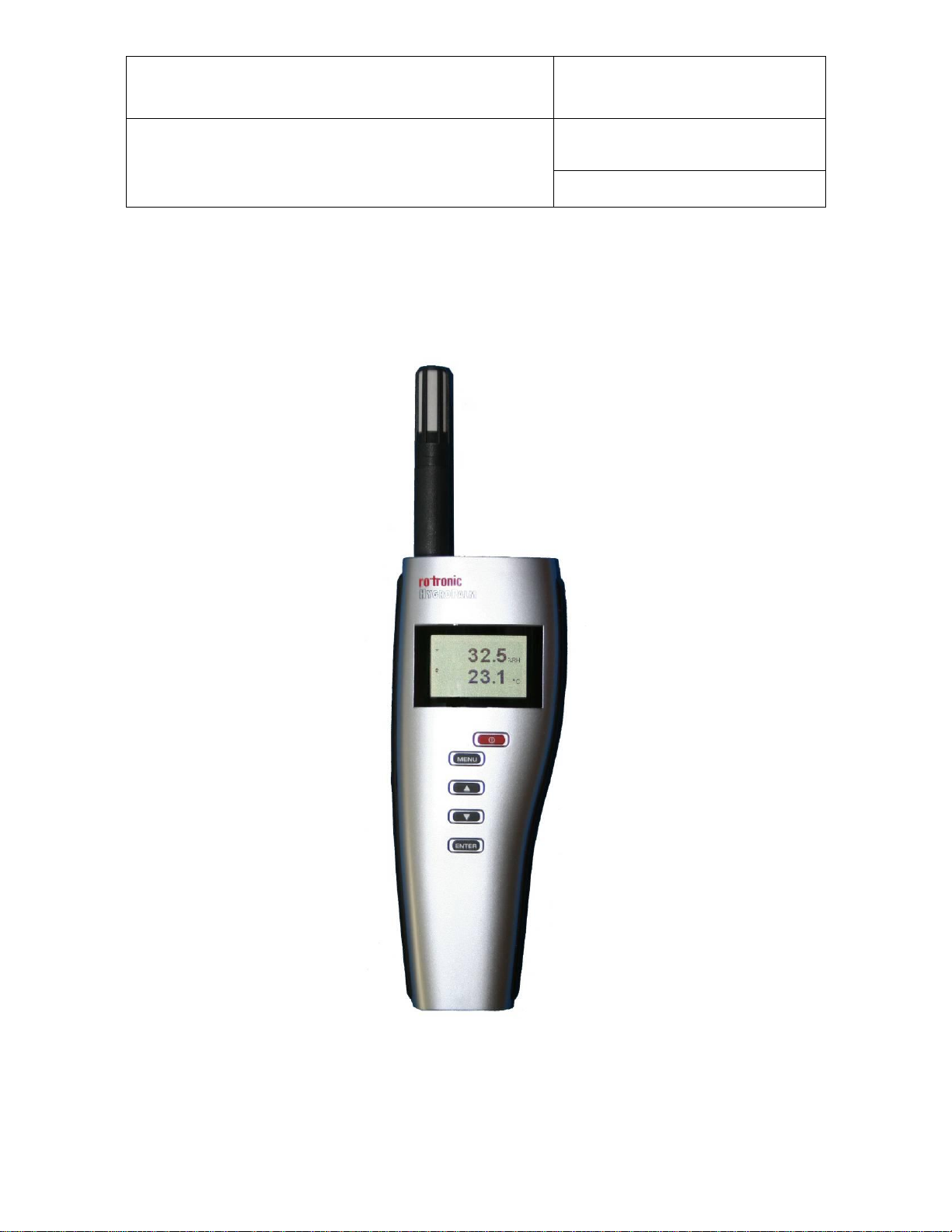
1 Overview
The HP21 is a highly accurate hand-held indicator that displays relative humidity, temperature and the dew or
frost point. The HP21 is perfect for spot checking HVAC installations, manufacturing and storage areas, and
generally for all ambient air measurement within the temperature range of -10 to 60°C (14 to 140 °F). The
HP21 operates with a regular 9V alkaline battery.
Based on the ROTRONIC AirChip 3000 digital technology the HP21 offers the following user functions:
User configurable settings
Calculation of the dew or frost point
Humidity temperature calibration and adjustment
Simulator mode
Automatic humidity sensor test and drift compensation
Sensor failure mode
Data recording
The ability for the user to easily update the AirChip 3000 firmware means that the HP21 can be kept up-todate regarding any future functionality improvement.
2 General description
2.1 Power supply
The HP21 operates with a regular 9V alkaline battery
2.2 Measured parameters
The HP21 measures relative humidity with a ROTRONIC Hygromer® IN1 capacitive sensor and temperature
with a Pt100 RTD.
2.3 Calculated parameters
Using the ROTRONIC HW4 software, the HP21 can be configured by the user to calculate either the dew
point or the frost point.
2.4 Sensor protection (dust filter)
The HP21 is supplied with a Polyethylene filter to protect the sensors against dust particles and high air
velocity.
© 2009-2010; Rotronic AG E-M-HP21-V1_21
Page 4

E-M-HP21-V1_21
Rotronic AG
Bassersdorf, Switzerland
Document code
Unit
HygroPalm HP21 hand-held indicator:
User Guide
Instruction Manual
Document Type
Page
4 of 14
Document title
MEASUREMENT ACCURACY AND RELIABILITY
AirChip 3000 Functions
Description
► Humidity / temperature adjustment
o 1-point or multi-point humidity calibration or adjustment
o 1-point or 2-point temperature calibration or adjustment
o Generate a time stamp for calibrations and adjustments
o Retain and view last adjustment date and adjustment values
o Generate calibration and adjustment protocols
► Automatic humidity sensor test
and optional drift compensation
Tests the humidity sensor for drift caused by contaminants and
can be used to automatically apply a correction. The test is
automatically carried out at regular intervals of time. Can be
configured, enabled, or disabled
The humidity sensor status can be verified either with the HW4
software or with the instrument display and is shown as Good,
SQ-tuned (corrected for drift) or Bad (defective)
2.5 Service connector
The service connector is a UART digital interface (Universal Asynchronous Receiver Transmitter) with a miniUSB type connector. This allows connecting the HP21 either to a PC running the ROTRONIC HW4 software
or to a probe input of another instrument that is compatible with the HygroClip 2 (HC2) probes. In both cases a
service cable is required. See “Maintenance” for the location of the service connector and for the type of
service cable to be used.
Connecting the HP21 to a PC is used to configure the HP21, gain access to the HP21 functions such as
humidity and temperature adjustment, read data from the HP21 on the PC and update the AirChip 3000
firmware.
Connecting the HP21 to another instrument is useful only when the other instrument has its own display
and keypad, and has a more powerful internal menu than the HP21 (example HP23 hand-held calibrator).
This allows showing the data measured by the HP21 on the other instrument display and also allows using
the other instrument internal menu to do for example a humidity and temperature adjustment of the HP21.
3 User configurable settings and functions
The HP21 can be used just as any conventional humidity and temperature indicator and most users will never
need to use the HP21 configurable settings and functions.
Making use of the HP21 configurable settings and functions is entirely up to the user and the appropriate
settings depend on the user application. We have provided below a short description of the HP21 functions
and also indicated the factory default settings.
3.1 Function overview
© 2009-2010; Rotronic AG E-M-HP21-V1_21
Page 5

E-M-HP21-V1_21
Rotronic AG
Bassersdorf, Switzerland
Document code
Unit
HygroPalm HP21 hand-held indicator:
User Guide
Instruction Manual
Document Type
Page
5 of 14
Document title
► Data recording
The data recording function differs from a true data logging
function in the sense that the AirChip 3000 does not time stamp
the data. This data recording function can be used to investigate
events such as a sensor malfunction as well as to retrieve data
that would otherwise be lost
o Start or stop data recording - up to 2000 value pairs (%RH
and temperature). Starting a recording session erases all
previously recorded data
o The recording mode and log interval can be specified
o When the device is powered off, the recording session is
paused but not ended As long as the recording session has
not been ended, the device automatically resumes recording
data when powered up again
o The recorded data can be downloaded to a PC with the
HW4 software, time stamped and viewed
MEASUREMENT LOOP VALIDATION
AirChip 3000 Functions
Description
► Simulator mode
Used to make the HP21 generate fixed values for the humidity,
temperature and calculated parameter. Can be configured,
enabled or disabled
DEVICE SAFEGUARDS
AirChip 3000 Functions
Description
► Device write protection
Used to protect the HP21 with a password to prevent
unauthorized digital access by a digital user. Can be configured,
enabled or disabled
► Internal menu access from keypad
Used to prevent accidental changes to the HP21 settings and
temperature-humidity adjustment by disabling the MENU key on
the keypad. Can be enabled or disabled
© 2009-2010; Rotronic AG E-M-HP21-V1_21
Page 6

E-M-HP21-V1_21
Rotronic AG
Bassersdorf, Switzerland
Document code
Unit
HygroPalm HP21 hand-held indicator:
User Guide
Instruction Manual
Document Type
Page
6 of 14
Document title
Configurable Settings
Factory default
Unit system
K
Metric, except USA: English
Psychrometric calculation
Dew / frost point
Display resolution
1 decimal
Display backlight
K
On Key Press
Displayed parameters
K
%RH and temperature
Trend indicator (display)
Enabled
Communication protocol
RO-ASCII
RS-485 address
0
Device name
Instrument model
Functions
Factory default
Humidity / temperature adjustment
K
Device write protection
Disabled
Menu access from keypad
Enabled
Limit humidity output to 100 %RH
Enabled
Out-of-limit value digital / display alarm
Disabled
Data recording
K
Enabled (loop mode – 10 min. interval)
Automatic humidity sensor test
Disabled
Humidity sensor drift compensation
Disabled
Simulator mode
Disabled
3.2 Factory default settings
Notes:
o Configuration of the HP21 by the user and access to its functions requires a PC with the ROTRONIC HW4
software (version 2.1.1 or higher) installed. Service cable AC3006 is used to connect the HP21 service
connector to a USB port of the PC.
o Settings and functions that can also be either partially or fully accessed from the keypad are marked with
the letter K (see also Operation > Internal Menu).
o For a detailed description of all AirChip 3000 / HP21 main functions see document E-T-AC3000-DF-V1
o Instructions regarding the configuration of the HP21 and access to its functions are provided in the
following manuals:
E-M-HW4v3-Main
E-M-HW4v3-F2-004
E-M-HW4v3-DR-001
E-M-HW4v3-A2-001
E-M-AC3000-CP
.
o The factory default setting for dew / frost point calculation is frost point below freezing
© 2009-2010; Rotronic AG E-M-HP21-V1_21
Page 7
E-M-HP21-V1_21
Rotronic AG
Bassersdorf, Switzerland
Document code
Unit
HygroPalm HP21 hand-held indicator:
User Guide
Instruction Manual
Document Type
Page
7 of 14
Document title
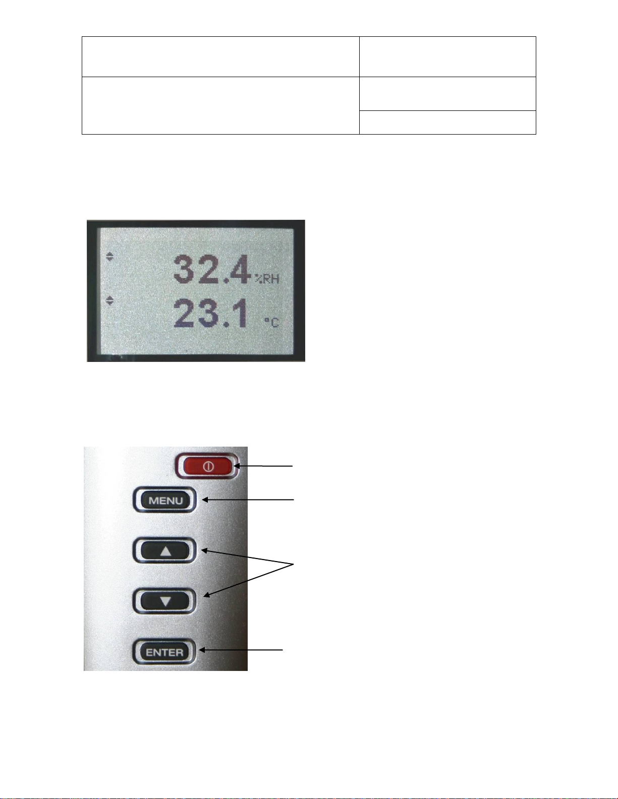
ON/OFF: Turns the instrument on or off
MENU: Press this key to activate the
internal menu. Press this key
again to exit the menu
UP / DOWN: When the menu is active, use these
keys to navigate the menu, make a
selection or change a value
ENTER: When the menu is active, press
this key to confirm a selection.
4 Operation
4.1 Display
The LC display of the HP21 has a backlight which
can be set to be on all the time or whenever a key is
pressed. The backlight can also be disabled.
The upper line corresponds to relative humidity or
dew / frost point and the bottom line corresponds to
temperature.
The display can be configured to show a trend
indicator on each line:
▲: increasing value
▼: decreasing value
In the event of an alarm the display shows the symbol [ ! ] to the right of the value.
For instructions see the following HW4 manual: E-M-HW4v3-F2-004.
4.2 Keypad
© 2009-2010; Rotronic AG E-M-HP21-V1_21
Page 8

E-M-HP21-V1_21
Rotronic AG
Bassersdorf, Switzerland
Document code
Unit
HygroPalm HP21 hand-held indicator:
User Guide
Instruction Manual
Document Type
Page
8 of 14
Document title
Main Menu
Menu Items
Selections / Information
Notes
Settings
Unit
°C / °F
Temperature / dew or frost point
Record
On / Off
Data recording (max. 2000 values)
Back Light
Key Press / On / Off
Display backlight mode
Device Information
Version
Firmware version
Serial Nbr
Serial number
Address
RS-485 address
Type
Device type
Name
Device name
User defined
SensorTest
Humidity sensor status
Off / Good / SQ-Tuned / Bad
Humidity Adjust
RefValue
Humidity reference value
± 0.1 %RH steps
<Adjust>
1-point adjustment only (offset)
Temperature Adjust
RefValue
Temperature reference value
± 0.1 ˚C steps
<Adjust>
1-point adjustment only (offset)
4.3 Internal menu
Note: Unauthorized access to the menu can be prevented by disabling the “display menu” setting
(use the HW4 software > Device Manager > Display)
Notes:
o Record: both the recording mode (start / stop and the log interval cannot be changed from the menu and
are as configured with the ROTRONIC HW4 software
o SensorTest: Off means that the humidity sensor has not been tested due to the configuration settings of
the test. For a description of the automatic humidity sensor test and drift compensation (SQ-tuning) see
documents E-T-AC3000-DF-V1 and E-M-HW4v3-F2-004
4.4 Changing the parameters shown on the display
When the menu is not active, press the ENTER key to change which parameters are shown on the display:
o Relative humidity and temperature
o Dew / frost point and temperature (when calculated parameter is enabled)
4.5 Changing the temperature unit
The temperature unit of the HP21 (°C or °F) can be changed from the keypad (Menu > Settings > Unit).
Press the MENU key to show the internal menu on the display
With the menu item Settings highlighted, press the ENTER key
With the menu item Unit highlighted, press the ENTER key
Use the UP or DOWN key to change the temperature unit as desired
Press the MENU key twice to exit the menu and return the HP21 to normal operation
© 2009-2010; Rotronic AG E-M-HP21-V1_21
Page 9

E-M-HP21-V1_21
Rotronic AG
Bassersdorf, Switzerland
Document code
Unit
HygroPalm HP21 hand-held indicator:
User Guide
Instruction Manual
Document Type
Page
9 of 14
Document title
The optional HW4 software can also be used to change the unit system:
4.6 Low battery indicator
When the battery is down to about 20% of its initial charge, “Low Battery” appears at the bottom of the display.
4.7 Practical advice for measuring humidity
The most common source of error when measuring relative humidity is a difference between the
temperature of the probe and the temperature of the environment. At a humidity condition of 50 %RH, a
temperature difference of 1 C (1.8 F) typically results in an error of 3 %RH on relative humidity.
When using the HP21 hand-held indicator, it is good practice to monitor the display for temperature
stability. The probe should be given sufficient time to equilibrate with the environment to be measured. The
larger the initial temperature difference between the probe and the environment to be measured, the more
time temperature equilibration requires. This time can be shortened, and errors avoided, by using the probe
configuration that fits best for your application.
In extreme situations, condensation may occur on the sensors when the probe is colder than the
environment. As long as the humidity / temperature limits of the humidity sensor are not exceeded,
condensation does not alter the calibration of the sensor. However, the sensor has to dry out before it can
provide a valid measurement.
Non-moving air is an excellent insulator. When there is no air movement, surprising differences in temperature
and humidity can noted over short distances. Air movement at the probe generally results in measurements
that are both faster and more accurate.
5 Maintenance
5.1 Service cable
Cable AC3006 converts UART (service connector) to USB and is used to connect the HP21 to a USB port
of a PC running the ROTRONIC HW4 software. Prior to using this cable, the ROTRONIC USB driver must
be installed on the PC. Both the driver and the installation instructions (document E-M-HW4v3-Main) are
located on the HW4 CD.
As an alternative, cable AC2001 is used to connect the HP21 to a probe input of the HP23 hand-held
calibrator. For service purposes, the HP23 offers essentially the same functionality as the HW4 software.
5.2 Location of the service connector (mini USB type)
WARNING: the service connector is a UART
interface with a mini-USB connector type. Do not
connect the service connector directly to the USB
port of a PC or hub.
The service connector (UART interface) can be
accessed without opening the enclosure after
removing the protective red round cover.
© 2009-2010; Rotronic AG E-M-HP21-V1_21
Page 10

E-M-HP21-V1_21
Rotronic AG
Bassersdorf, Switzerland
Document code
Unit
HygroPalm HP21 hand-held indicator:
User Guide
Instruction Manual
Document Type
Page
10 of 14
Document title
5.3 Periodic calibration check
Both the Pt 100 RTD temperature sensor and associated electronics are very stable and should not
require any calibration after the initial factory adjustment.
Long term stability of the ROTRONIC Hygromer humidity sensor is typically better than 1 %RH per year.
For maximum accuracy, calibration of the HP21 should be verified every 6 to 12 months. Applications
where the HP21 is exposed to significant pollution may require more frequent verifications.
a) Procedure for adjusting the HP21 from the keypad
The keypad of the HP21 allows a 1-point adjustment of temperature or humidity against a reference.
A 1-point adjustment has the effect of adding the same offset to all measured values. A multi-point
adjustment is not possible from the keypad and requires using either a PC with the HW4 software
installed or the HP23 hand-held calibrator.
When the parameter to be adjusted is stable, press the MENU key to show the internal menu on the
display
Use the DOWN key to select either H-Adjust or T-Adjust and press the ENTER key
Make sure that the text line beginning with RefValue is highlighted and press the ENTER key
Use the UP or DOWN key to change the reference value as desired
Use the DOWN key to highlight the Adjust text line and press the ENTER key
The HP21 confirms the adjustment with the message “Adjust OK”
Press the MENU key twice to exit the menu and return the HP21 to normal operation
Notes:
o The calibration point is automatically deleted from the probe memory after an adjustment
o Instructions for using the ROTRONIC calibration devices and humidity standards are provided in
document E-M-CalBasics
o Because the HP21 has no real time clock, the date of the adjustment is not written to the HP21. If
retaining the adjustment date is important, use the HW4 software to adjust the HP21.
b) Procedure for adjusting the HP21 with the ROTRONIC HW4 software:
Use cable AC3006 to connect the service connector of the HP21 to the USB port of a PC with the
ROTRONIC HW4 software installed. Note that the ROTRONIC USB driver must be installed on the
PC as explained in the HW4 manual E-M-HW4v3-Main
Start HW4 on the PC and search for the HP21(HW4 Main Menu Bar > Devices and Groups > Search
for USB Masters).
After finding the HP21 with HW4, expand the device tree to see the HP21 functions.
Select Probe Adjustment.
For further instructions see HW4 manual E-M-HW4v3-A2-001
© 2009-2010; Rotronic AG E-M-HP21-V1_21
Page 11
E-M-HP21-V1_21
Rotronic AG
Bassersdorf, Switzerland
Document code
Unit
HygroPalm HP21 hand-held indicator:
User Guide
Instruction Manual
Document Type
Page
11 of 14
Document title
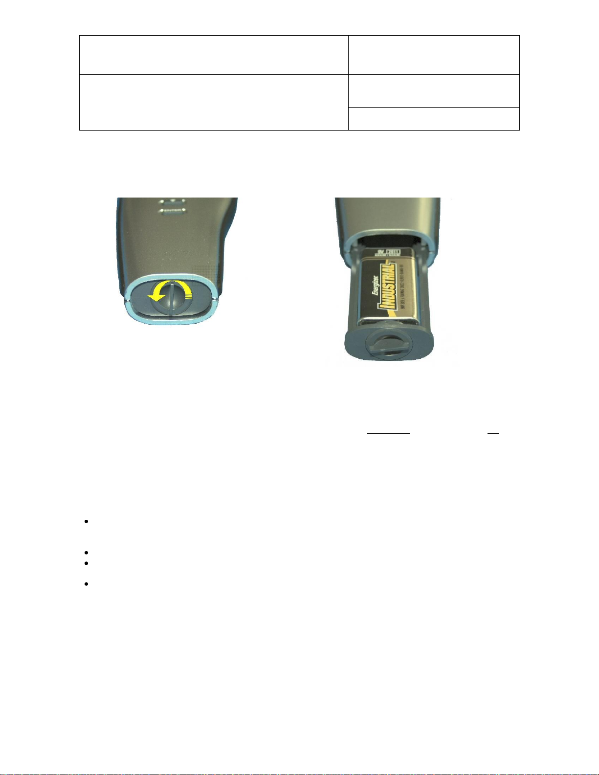
5.4 Replacing the battery
To replace the battery, turn the latching button counter-clockwise and pull out the battery holder.
5.5 Cleaning or replacing the dust filter
Depending on the application, the dust filter may require cleaning from time to time, Cleaning should be done
without removing the filter from the probe. Clean the filter with a fine brush. If this is not sufficient, the filter
should be replaced. To do this, unscrew the filter from the probe. Before putting on a new dust filter, check the
alignment of both sensors with the probe. The wires that connect the sensors to the probe are very thin and
bend easily. If this happens, correct the alignment by holding the sensor very gently with a pair of small flat
nosed pliers.
6 Firmware updates
Firmware updates will be available on the ROTRONIC website for downloading. Firmware files are given a
name that shows both to which device the file applies and the version number of the firmware. All firmware
files have the extension HEX. Procedure for updating the firmware:
Use cable AC3006 to connect the service connector of the HP21 to the USB port of a PC with the
ROTRONIC HW4 software installed. Note that the ROTRONIC USB driver must be installed on the
PC as explained in the HW4 manual E-M-HW4v3-Main
Copy the firmware update file from the ROTRONIC website to the PC.
Start HW4 software on the PC and search for the HP21 (HW4 Main Menu Bar > Devices and Groups
> Search for USB Masters).
After finding the HP21, expand the device tree to see the HP21 functions. Select Device Manager. In
the Device Manager menu bar select Tools > Firmware Update. For instructions see document
E-M-HW4v3-F2-004
© 2009-2010; Rotronic AG E-M-HP21-V1_21
Page 12

E-M-HP21-V1_21
Rotronic AG
Bassersdorf, Switzerland
Document code
Unit
HygroPalm HP21 hand-held indicator:
User Guide
Instruction Manual
Document Type
Page
12 of 14
Document title
General
HP21
Device type
Humidity-temperature hand-held indicator with integral probe
Battery type
9 V alkaline
Low battery indication
Yes
Humidity measurement
HP21
Sensor
ROTRONIC Hygromer ® M1-R
Measuring range
0…100 %RH
Measurement accuracy at 23 °C
±1.0 %RH
Repeatability
0.3 %RH
Long term stability
< 1 %RH / year
Sensor time constant
Typical 10 sec, 63% of a 35 to 80 %RH step change (1m/sec air flow at sensor)
Temperature measurement
HP21
Sensor
Pt100 RTD, IEC 751 1/3 class B
Measuring range
-10...60°C
Measurement accuracy at 23 °C
±0.2 °C
Repeatability
0.05°C
Long term stability
< 0.1°C / year
Sensor time constant
Typical 4 sec, 63% of a step change (1m/sec air flow at sensor)
Calculated parameters
HP21
Psychrometric calculations
Dew or frost point (user configurable setting)
Start-up time and data refresh rate
HP21
Start-up time
1.9s (typical)
Data refresh rate
1.7s (typical)
Service connector
HP21
Interface type
UART (Universal Asynchronous Receiver Transmitter)
Maximum service cable length
5 m (16.4 ft)
General specifications
HP21
Display
LC, 1 or 2 decimals resolution, backlight, trend, alarm and low battery indication
Probe material
Polycarbonate
Probe dust filter material
Polyethylene
Housing material
ABS
Housing protection grade
IP 40
Overall dimensions
270 x 70 x 30 mm (10.63 x 2.76 x 1.17”)
Probe dimensions
80 x 15 mm (3.15 x 0.59”)
Weight
About 198 g (7.0 oz)
7 Technical data
7.1 Specifications
© 2009-2010; Rotronic AG E-M-HP21-V1_21
Page 13

E-M-HP21-V1_21
Rotronic AG
Bassersdorf, Switzerland
Document code
Unit
HygroPalm HP21 hand-held indicator:
User Guide
Instruction Manual
Document Type
Page
13 of 14
Document title
Conformity with standards
HP21
CE / EMC immunity
EMC Directive 2004/108/EG: EN 61000-6-1: 2001, EN 61000-6-2: 2005
EN 61000-6-3: 2005, EN 61000-6-4: 2001 + A11
Solder type
Lead free (RoHS directive)
FDA / GAMP directives
compatible
Environmental limits
HP21
Storage and transit
-20…+70 °C / 0…100 %RH, non condensing
Operating limits at electronics
-10….60 °C (limited by LC display)
0…100 %RH, non condensing
Temperature limits at probe
Same as electronics
Maximum humidity at probe
Same as electronics
Maximum air velocity at probe
20 m/s (3,935 ft /min)
Critical environments
Humidity sensor: as per DV04-14.0803.02 - Critical chemicals
7.2 Dew point accuracy
The HP21 can be configured to calculate either the dew point or frost point based on the measurement of
relative humidity and temperature. The accuracy of this conversion varies, depending on the humidity and
temperature conditions as shown in the graph below:
Example: at a temperature of 20 ˚C, a dew point value of -37 ˚C is measured with an accuracy of
± 1.0 ˚C or better.
© 2009-2010; Rotronic AG E-M-HP21-V1_21
Page 14

E-M-HP21-V1_21
Rotronic AG
Bassersdorf, Switzerland
Document code
Unit
HygroPalm HP21 hand-held indicator:
User Guide
Instruction Manual
Document Type
Page
14 of 14
Document title
Document File Name
Contents
E-M-HC2-accessories
Accessories and parts for probes, indicators and transmitters
E-T-AC3000-DF-V1
AirChip 3000 Description and Main Functions
E-M-HW4v3-DIR
List of the HW4 manuals
E-M-HW4v3-Main
HW4 software version 3: General instructions and functions common to all
devices
E-M-HW4v3-F2-004
HW4 software version 3: HP21 hand-held indicator
Device configuration and AirChip 3000 functions
E-M-HW4v3-A2-001
HW4 software version 3: Probe Adjustment function AirChip 3000 devices
E-M-HW4v3-DR-001
HW4 software version 3: Data Recording Function AirChip 3000 Devices
E-M-AC3000-CP
AirChip 3000 Communication Protocol
E-M-CalBasics
Temperature and humidity calibration basics
Instructions for using the ROTRONIC humidity standards
E-T-HumiDefs
Humidity Definitions
Doc. Release
Date
Notes
_20
Apr. 3, 2009
Original release
_21
Jun. 20, 2010
Updated document to HW4 software v.3
8 Accessories
For accessories and parts such as the HW4 configuration software, service cables, calibration accessories
and spare dust filters, please see document E-M-HC2-accessories
9 Supporting documents
Note: All document file names have an extension corresponding to the document release number. This
extension is not shown in the above table.
10 Document releases
© 2009-2010; Rotronic AG E-M-HP21-V1_21
 Loading...