

Page 1
E-M-HM4-V0_08
ROTRONIC AG
Bassersdorf, Switzerland
Document Code
Unit
HM4 Humidity and Temperature Probe with
Heated Sensor
Instruction Manual
Document Type
Page
1 of 41
Document Title
DRAFT
HM4
Humidity and Temperature Probe
with Heated Sensor
Instruction Manual
© 2014; ROTRONIC AG E-M-HM4-V0_08
Page 2

E-M-HM4-V0_08
ROTRONIC AG
Bassersdorf, Switzerland
Document Code
Unit
HM4 Humidity and Temperature Probe with
Heated Sensor
Instruction Manual
Document Type
Page
2 of 41
Document Title
DRAFT
Table of Contents
1 Overview ............................................................................................................................................... 4
1.1 Scope ................................................................................................................................................. 5
1.2 Background Information on the Principle of Measurement ................................................................. 5
2 Mechanical Variants and Dimensions ................................................................................................ 6
3 General ................................................................................................................................................. 7
3.1 Power Supply ..................................................................................................................................... 7
3.2 Measured Parameters ........................................................................................................................ 7
3.3 Calculated Parameters ....................................................................................................................... 8
3.4 Analog Outputs................................................................................................................................... 9
3.5 RS-485 Interface .............................................................................................................................. 11
3.6 HW4 Software Compatibility ............................................................................................................. 12
3.7 Real-Time Clock ............................................................................................................................... 12
3.8 Sensor Filter ..................................................................................................................................... 12
4 User-Specific Settings and Functions ............................................................................................. 13
4.1 General AirChip3000 Functions ....................................................................................................... 13
4.2 Factory Defaults ............................................................................................................................... 19
5 Mechanical Installation ...................................................................................................................... 20
5.1 General ............................................................................................................................................ 20
6 Electrical Installation ......................................................................................................................... 21
6.2 Wiring ............................................................................................................................................... 23
6.3 Tuchel Connector Pin Configuration................................................................................................. 24
6.4 Cable Connection with Open Ends................................................................................................... 25
7 Operation ............................................................................................................................................ 26
7.1 Load Resistance Requirements of the Analog Outputs .................................................................... 26
7.2 RS-485 Interface .............................................................................................................................. 27
8 Maintenance ................................................................................................ ....................................... 29
8.1 Service Cable ................................................................................................................................... 29
8.2 Calibration ........................................................................................................................................ 30
8.3 Filter Maintenance ............................................................................................................................ 31
8.4 Validation of the Analog Outputs ...................................................................................................... 31
9 Firmware Update ................................................................................................................................ 32
10 Technical Data.................................................................................................................................... 33
© 2014; ROTRONIC AG E-M-HM4-V0_08
Page 3

E-M-HM4-V0_08
ROTRONIC AG
Bassersdorf, Switzerland
Document Code
Unit
HM4 Humidity and Temperature Probe with
Heated Sensor
Instruction Manual
Document Type
Page
3 of 41
Document Title
DRAFT
10.1 Dew Point Accuracy ......................................................................................................................... 38
11 Accessories ........................................................................................................................................ 39
12 Additional Documents ....................................................................................................................... 40
13 Document Versions ........................................................................................................................... 41
© 2014; ROTRONIC AG E-M-HM4-V0_08
Page 4

E-M-HM4-V0_08
ROTRONIC AG
Bassersdorf, Switzerland
Document Code
Unit
HM4 Humidity and Temperature Probe with
Heated Sensor
Instruction Manual
Document Type
Page
4 of 41
Document Title
DRAFT
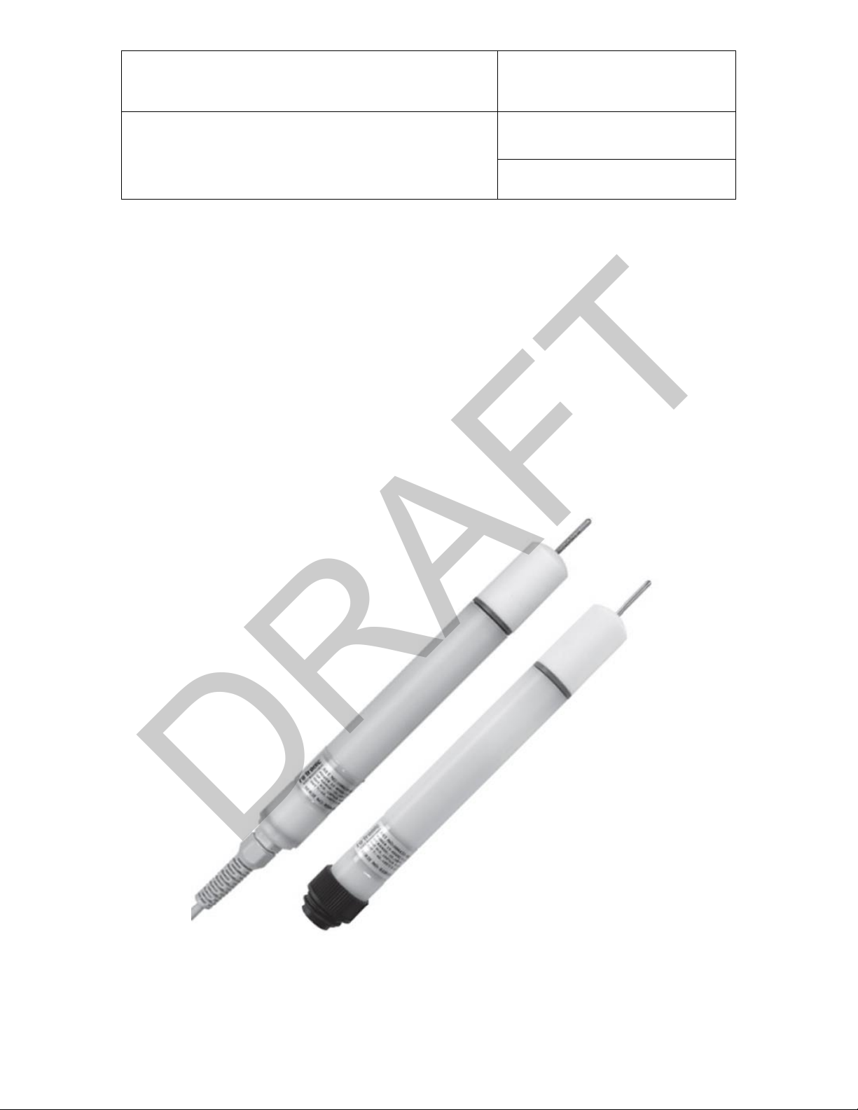
1 Overview
The HygroMet4 (HM4) series of devices are digital humidity and temperature probes based on ROTRONIC
AirChip3000 technology. The probe permits heating of the sensor during humidity and temperature
measurement. It was developed for use in meteorological applications and wherever high humidity and the risk
of condensation on the sensor is likely.
The HM4 has two freely configurable and user adjustable linear analog outputs (voltage/current). It also has a
RS-485 interface for direct exporting of measured values with the HW4 software and configuration of the probe.
The manual E-M-HW4v3-F2-023 describes all software functions. Using the RS-485 interface, it is possible to
build a network of up to 64 simultaneously evaluable HM4 probes.
The HM4 offers the following user functions:
Simultaneous measurement and heating
Measurement of relative humidity and temperature and calculation of all psychrometric parameters
Freely programmable sensor heating (RoHumiHeat) prevents condensation on the sensor
Adjustable sensor cleaning (RoHumiClean) to minimise soiling of the sensor
SMD Thermo sensor element
Outstanding accuracy and repeatability
Integrated real-time clock
Freely scalable analog output signals
RS-485 interface
Calibration / Adjustment of humidity and temperature measured values
Simulation mode
User-specific device settings
Simple updating of the AirChip3000 firmware keeps the devices in the HM4 series up to date with improved
functionality.
© 2014; ROTRONIC AG E-M-HM4-V0_08
Page 5
E-M-HM4-V0_08
ROTRONIC AG
Bassersdorf, Switzerland
Document Code
Unit
HM4 Humidity and Temperature Probe with
Heated Sensor
Instruction Manual
Document Type
Page
5 of 41
Document Title
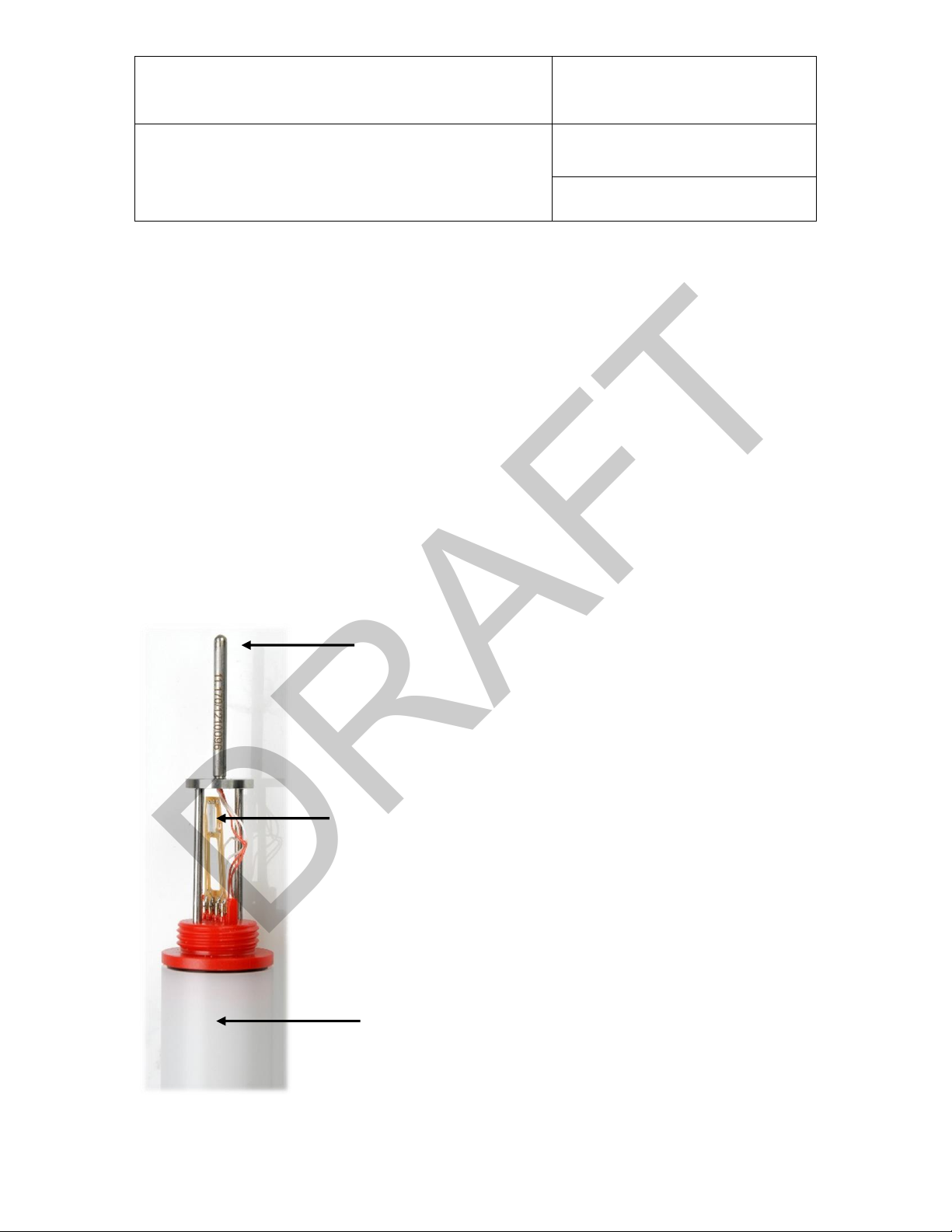
Pt100 temperature sensor
Inside: Evaluation electronics with AirChip3000 and real-time clock
Heated SMD Thermo humidity sensor
DRAFT
1.1 Scope
This manual is valid for the HM4 probe series with firmware version V1.1. The low-order digit of the firmware
version stands for minor changes, e.g. correction of errors, that do not influence the main functionality of the
device.
1.2 Background Information on the Principle of Measurement
In environments with high humidity (>90 %RH) near saturation point there is a risk of condensation forming on
the humidity sensor. To avoid resultant incorrect measurement, the sensor can be heated above ambient
temperature to avoid condensation. The same applies for outdoor measurements in mist or high levels of dew.
The probes in the HygroMet4 series from ROTRONIC (HM4) measure temperature and humidity
simultaneously. Formation of condensation on the capacitive SMD humidity sensor can be prevented by raising
the temperature above ambient temperature, thereby enabling accurate humidity measurements even when the
measurement environment has already reached dew point (100 %RH).
© 2014; ROTRONIC AG E-M-HM4-V0_08
Page 6
E-M-HM4-V0_08
ROTRONIC AG
Bassersdorf, Switzerland
Document Code
Unit
HM4 Humidity and Temperature Probe with
Heated Sensor
Instruction Manual
Document Type
Page
6 of 41
Document Title
DRAFT
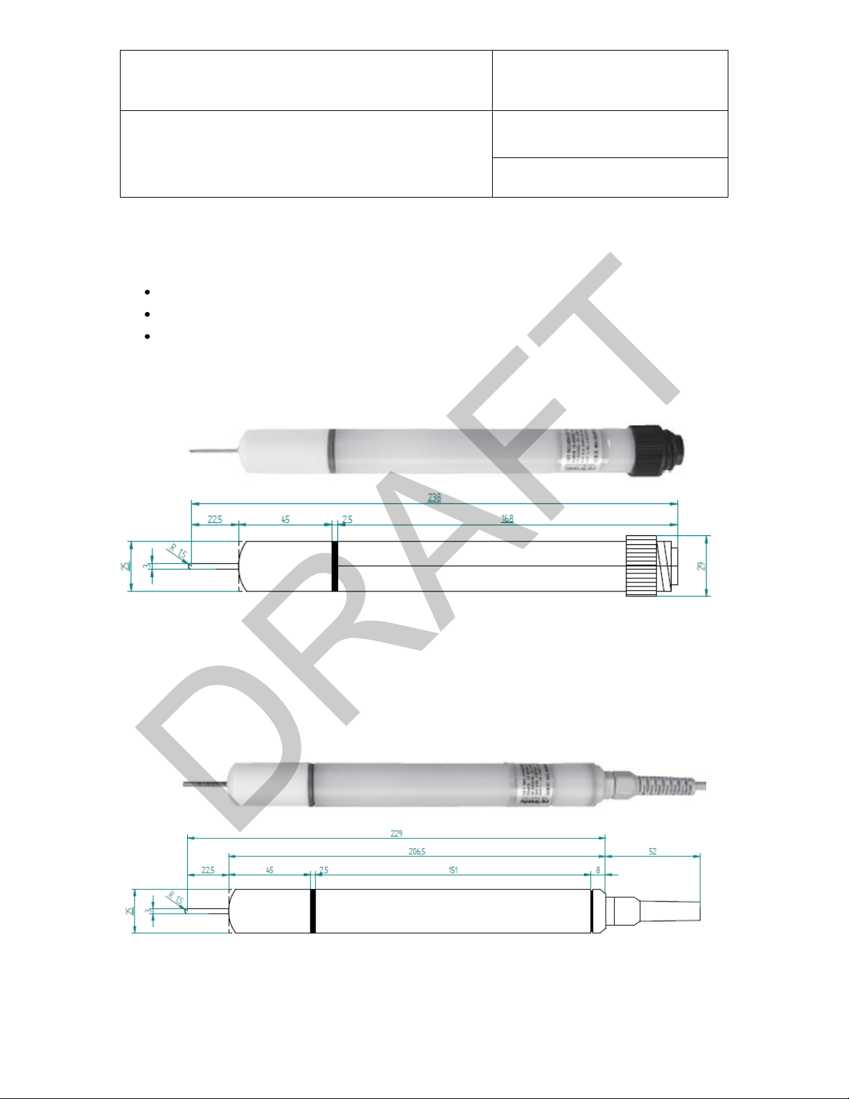
2 Mechanical Variants and Dimensions
The HM4 is a new development from ROTRONIC and comes in three variants.
Connector directly at the housing
Connector on remote cable
Cable with open ends
2.1.1 HM4 with 7-Pin Tuchel Connector at Housing
Figure 1: Dimensions of the HygroMet4 with Tuchel connector at the housing in mm
2.1.2 HM4 with Cable
The HM4 is available with a cable length of 2 m or 5 m. The cable is available with open ends or Tuchel T7
connectors.
Figure 2: Dimensions of the HygroMet4 with cable in mm
© 2014; ROTRONIC AG E-M-HM4-V0_08
Page 7

E-M-HM4-V0_08
ROTRONIC AG
Bassersdorf, Switzerland
Document Code
Unit
HM4 Humidity and Temperature Probe with
Heated Sensor
Instruction Manual
Document Type
Page
7 of 41
Document Title
Operating State
Current Consumption
5 VDC, without heater
<35 mA
5 VDC, with heater
<55 mA
24 VDC, without heater
<20 mA
24 VDC, with heater
<30 mA
DRAFT
3 General
3.1 Power Supply
The HM4 requires a power supply of 15...24 VDC (55 mA) for full functionality, but may already be operated on
5 VDC with the following restrictions:
Analog output only 0...1 V
RoHumiClean function only available to a limited extent (see chapter 4.1.6)
Detailed Power Supply Specifications:
3.2 Measured Parameters
The HM4 measures relative humidity and temperature. The heated SMD humidity sensor allows simultaneous
heating and measurement. The temperature is measured at the tip of the probe by an external Pt100 sensor.
© 2014; ROTRONIC AG E-M-HM4-V0_08
Page 8

E-M-HM4-V0_08
ROTRONIC AG
Bassersdorf, Switzerland
Document Code
Unit
HM4 Humidity and Temperature Probe with
Heated Sensor
Instruction Manual
Document Type
Page
8 of 41
Document Title
DRAFT
3.3 Calculated Parameters
The HM4 can calculate all psychrometric parameters and assign them to the outputs with the HW4 software.
Dew point (Dp)
Frost point (Fp)
Wet bulb temperature (Tw)
Enthalpy (H)
Vapour concentration (Dv)
Specific humidity (Q)
Mixing ratio (R)
Saturation vapour concentration (Dvs)
Vapour partial pressure (E)
Water vapour saturation pressure (Ew)
Remark:
The above parameters are dependent on barometric pressure. Using the HW4 software, it is possible to store
the barometric pressure at the probe in the HM4 probe. Programming of the HM4 with the HW4 software is
described in the manual E-M-HW4v3-F2-023.
© 2014; ROTRONIC AG E-M-HM4-V0_08
Page 9

E-M-HM4-V0_08
ROTRONIC AG
Bassersdorf, Switzerland
Document Code
Unit
HM4 Humidity and Temperature Probe with
Heated Sensor
Instruction Manual
Document Type
Page
9 of 41
Document Title
Output
Scale
Output 1 (Out1)
0…100 %RH
Output 2 (Out2)
-40…60 °C
DRAFT
3.4 Analog Outputs
The ROTRONIC HW4 software enables free configuration and scaling of the analog outputs. The measured
values (humidity, temperature) and resultant calculated values can thus be assigned to the analog outputs
(Out1, Out2) and scaled at will. The output variants (current or voltage) are defined by the order code. They
may be changed at will without need to recalibrate the device.
Default scaling of the outputs ex works:
The scale of the output variables and assignment of the measured variables to the outputs can be changed at
will with the HW4 software. The following output variables are available to the user:
Relative humidity
Temperature
Calculated parameters
By scaling, the user can set the limits of the temperature and measurement range freely to any values between
-999 and +9,999. Temperature measurements are possible in the following units:
°C (degrees Celsius)
°F (degrees Fahrenheit)
© 2014; ROTRONIC AG E-M-HM4-V0_08
Page 10

E-M-HM4-V0_08
ROTRONIC AG
Bassersdorf, Switzerland
Document Code
Unit
HM4 Humidity and Temperature Probe with
Heated Sensor
Instruction Manual
Document Type
Page
10 of 41
Document Title
Order Code
Signal Type
Maximum Offset
HM431
0…20 mA
20 µA
HM432
4…20 mA
No offset
HM433
0…1 V
1 mV
HM434
0…5 V
10 mV
HM435
0…10 V
10 mV
DRAFT
The analog outputs have a resolution of 16 bit and, depending on the output variant, a maximum offset as
named in the table below.
Important:
The maximum load values and minimum load resistances must be taken into account for the current and voltage
outputs. See chapter 10 for details.
© 2014; ROTRONIC AG E-M-HM4-V0_08
Page 11

E-M-HM4-V0_08
ROTRONIC AG
Bassersdorf, Switzerland
Document Code
Unit
HM4 Humidity and Temperature Probe with
Heated Sensor
Instruction Manual
Document Type
Page
11 of 41
Document Title
DRAFT
3.5 RS-485 Interface
The RS-485 interface is used to connect the HM4 to a PC. A PC running the HW4 software (Professional
version) offers the following functions:
Recording and display of current measured and calculated values
Configuration of the probe
Calibration and adjustment of the probe
Depending on the type of probe connection (Tuchel connector / open ends), different accessories are needed
to connect the HM4 to a PC.
Tuchel connector:
HM4 probes with Tuchel connector are connected with AC3010-T (RS-485-to-USB adapter). The
device can then be found and integrated using the HW4 software:
Devices & Groups > RS485 > Search for Devices connected via AC3010 adapter
Open ends:
HM4 probes with open cable ends require AC3010 (RS-485-to-USB adapter) or AC3011 (RS-485-toEthernet adapter). Both adapters allow a RS-485 network with up to 64 probes. The device can then
be found and integrated using the HW4 software:
Devices & Groups > RS485 > Search for Devices connected via AC3010 adapter
Devices and Groups > RS485 > Search for Devices connected via AC3011 adapter
See the manual E-M-HW4v3-Main, points 6.4, 7.5 and 11.2.2, for detailed information on building RS-485
networks and integrating HM4 probes in the HW4 software. Accessories such as AC3010 and AC3011 are
described in the manual E-M-HC2-accessories.
© 2014; ROTRONIC AG E-M-HM4-V0_08
Page 12

E-M-HM4-V0_08
ROTRONIC AG
Bassersdorf, Switzerland
Document Code
Unit
HM4 Humidity and Temperature Probe with
Heated Sensor
Instruction Manual
Document Type
Page
12 of 41
Document Title
DRAFT
3.6 HW4 Software Compatibility
The devices in the HM4 series are fully integrated in the HW4 software V3.4 and later.
3.7 Real-Time Clock
The HM4 probes are equipped with a battery-powered real-time clock. The button battery of the type CR-1220
guarantees clock operation for a period of about 10 years. The battery of the real-time clock is only used when
the HM4 is not connected to an external power supply.
The real-time clock is set ex works and can be readjusted with the HW4 software. The maximum rate deviation
of the clock is ±5 minutes per month (<116 ppm).
3.8 Sensor Filter
The probe must be protected at all times against dust and weather influences by a polyethylene filter. The filter
has a pore size of 20 µm (ROTRONIC order code: NSP-25-PE).
© 2014; ROTRONIC AG E-M-HM4-V0_08
Page 13

E-M-HM4-V0_08
ROTRONIC AG
Bassersdorf, Switzerland
Document Code
Unit
HM4 Humidity and Temperature Probe with
Heated Sensor
Instruction Manual
Document Type
Page
13 of 41
Document Title
Humidity and Temperature Adjustment
One-point or multi-point humidity calibration and adjustment
One-point and two-point temperature calibration and adjustment
Time stamp for every calibration and adjustment point
Saving and display of the last adjustment data and values
Creation of a calibration and adjustment log
Simulation Mode
Defines freely selectable values at the analog and digital outputs. Simulation mode is enabled/disabled with
the HW4 software.
DRAFT
4 User-Specific Settings and Functions
The HM4 has a variety of functions and settings that can be adapted by users to their requirements. This chapter
contains an overview of all functions and their default settings.
4.1 General AirChip3000 Functions
This section outlines the general functions of the AirChip family available in the HM4. All functions can be used
with the HW4 software and are described in detail in the manual E-M-HW4v3A2-001.
4.1.1 Humidity and Temperature Measurement
IMPORTANT:
All heating and cleaning functions must be switched off during calibration and adjustment!
4.1.2 Device Validation
© 2014; ROTRONIC AG E-M-HM4-V0_08
Page 14

E-M-HM4-V0_08
ROTRONIC AG
Bassersdorf, Switzerland
Document Code
Unit
HM4 Humidity and Temperature Probe with
Heated Sensor
Instruction Manual
Document Type
Page
14 of 41
Document Title
Write Protection
The device settings can be protected with a password. Password protection is configured with the HW4
software.
Limitation of the Humidity Value
The humidity measured value can be limited to 100 %RH.
Out-of-Limits Value Alarm
Specific limit values can be defined for humidity, temperature and the calculated values; an alarm is shown
in the HW4 software when they are exceeded.
The alarm function can be enabled or disabled.
Bad Sensor Alarm
This function is a fixed component of the HM4 firmware and cannot be disabled. A short circuit at the sensor
triggers a digital alarm, which is shown in the HW4 software.
DRAFT
4.1.3 Write Protection for Device Settings
4.1.4 Alarm Functions
© 2014; ROTRONIC AG E-M-HM4-V0_08
Page 15

E-M-HM4-V0_08
ROTRONIC AG
Bassersdorf, Switzerland
Document Code
Unit
HM4 Humidity and Temperature Probe with
Heated Sensor
Instruction Manual
Document Type
Page
15 of 41
Document Title
Sensor Heating (RoHumiHeat), Permanent
ROTRONIC recommends this operating mode! It guarantees the highest operating reliability and measuring
accuracy!
The humidity sensor is heated permanently. The heating rate is controlled by the ambient temperature.
The nominal temperature can be set with the HW4 software at will between 0.1 and 10 °C above ambient temperature.
The mode "permanent sensor heating" is factory set on a difference of 3 °C above ambient temperature. Temperature
differences of more than 3 °C between the sensor and environs caused by heating can have effects on the external
temperature measurement. This is particularly possible in stagnant air because the heat energy is then not dissipated
efficiently.
The function "permanent sensor heating" can be enabled/disabled with the HW4 software.
DRAFT
4.1.5 Sensor Heating (RoHumiHeat)
The sensor heating can be operated in three different modes.
Permanent
Time-dependent
Value-dependent
Start Response
When changing from an unheated to a heated state, there is a transient phase in which the sensor is heated to
above ambient temperature. Values measured by the probe are not refreshed for a time of 60 seconds until the
heater has stabilised at the set temperature.
Stop Response
When changing from a heated to an unheated state, there is, analogously to the start response, a transient
phase in which the sensor cools down to ambient temperature. The probe does not refresh measured values
for a time of four minutes after being switched off until this state has been reached.
© 2014; ROTRONIC AG E-M-HM4-V0_08
Page 16

E-M-HM4-V0_08
ROTRONIC AG
Bassersdorf, Switzerland
Document Code
Unit
HM4 Humidity and Temperature Probe with
Heated Sensor
Instruction Manual
Document Type
Page
16 of 41
Document Title
Sensor Heating (RoHumiHeat), Time-Dependent
The sensor heating can be activated cyclically. The following time intervals are available:
Hourly
Daily
Weekly
Monthly
The duration of the heating cycle is also freely selectable in minutes.
The temperature of the heated sensor can be selected freely between 0.1 °C and 10 °C above ambient
temperature.
ROTRONIC offers the time-dependent heating function as a feature for applications in which cyclical heating
suffices. Please note, however, that condensation could form on the sensor in an unheated state. If
condensation does form on the sensor when it is in operation, it can only be removed reliably with the
RoHumiClean function (five minutes cleaning at 150 °C).
Temperature differences of more than 3 °C between the sensor and environs caused by heating can have
effects on the external temperature measurement. This is particularly possible in stagnant air because the
heat energy is then not dissipated efficiently.
The start and stop responses follow the general function description above. The function "time-dependent
sensor heating" can be enabled/disabled with the HW4 software.
DRAFT
© 2014; ROTRONIC AG E-M-HM4-V0_08
Page 17

E-M-HM4-V0_08
ROTRONIC AG
Bassersdorf, Switzerland
Document Code
Unit
HM4 Humidity and Temperature Probe with
Heated Sensor
Instruction Manual
Document Type
Page
17 of 41
Document Title
Sensor Heating (RoHumiHeat), Value-Dependent
The sensor heating can be activated on the basis of definable temperature/humidity values.
Below a definable temperature threshold value
Above a definable temperature threshold value
Below a definable humidity threshold value
Above a definable humidity threshold value
The sensor heating is then activated as long as the measured temperature or humidity is below or above the
threshold value defined.
The temperature of the humidity sensor can be selected freely between 0.1 °C and 10 °C above ambient
temperature.
ROTRONIC offers the value-dependent heating function for applications in which value-dependent heating
suffices. Please note, however, that condensation could form on the sensor in an unheated state. If
condensation does form on the sensor when it is in operation, it can only be removed reliably with the
RoHumiClean function (five minutes cleaning at 150 °C).
Temperature differences of more than 3 °C between the sensor and environs caused by heating can have
effects on the external temperature measurement. This is particularly possible in stagnant air because the
heat energy is then not dissipated efficiently.
The start and stop responses follow the general function description above. The function "value-dependent
sensor heating" can be enabled/disabled with the HW4 software.
DRAFT
© 2014; ROTRONIC AG E-M-HM4-V0_08
Page 18

E-M-HM4-V0_08
ROTRONIC AG
Bassersdorf, Switzerland
Document Code
Unit
HM4 Humidity and Temperature Probe with
Heated Sensor
Instruction Manual
Document Type
Page
18 of 41
Document Title
DRAFT
4.1.6 Sensor Cleaning (RoHumiClean)
Sensor cleaning can take place in three time intervals.
Daily
Weekly
Monthly
The duration of the cleaning cycle is freely selectable in minutes. The cleaning temperature can be set up to
150 °C. No measurements are carried out during the cleaning phase. The last measured value is frozen until
the cleaning cycle is finished.
Stop Response
After cleaning, the sensor needs to cool down. No values are measured for a time of five minutes after
cleaning until this state has been reached.
Working Principle
Heating of the sensor up to 150 °C removes volatile and non-volatile contaminants. The sensor is thus cleaned
and, if water has entered the housing, dried completely. This prevents electrochemical corrosion.
Note:
When the sensor is heated to 150 °C, a drop of water on the surface of the sensor evaporates in about three
minutes.
A minimum power supply of 15 VDC is needed to initiate sensor cleaning manually with the HW4 software. If
this is not available in the field application, the function is still activated, but might not reach the required
temperature. The limit values are as follows:
Power supply: 15 VDC attainable heating temperature: 150 °C
Power supply: 10 VDC attainable heating temperature: 100 °C
Power supply: 5 VDC attainable heating temperature: 35 °C
The function can be enabled/disabled with the HW4 software.
© 2014; ROTRONIC AG E-M-HM4-V0_08
Page 19

E-M-HM4-V0_08
ROTRONIC AG
Bassersdorf, Switzerland
Document Code
Unit
HM4 Humidity and Temperature Probe with
Heated Sensor
Instruction Manual
Document Type
Page
19 of 41
Document Title
Configurable Setting
Factory Default
Unit of measurement (Metric / English)
Metric
Analog output
Dependent on order code
Psychrometric calculations
Disabled
Analog output 1:
Scale, parameter, unit
0…100 %RH
Analog output 2:
Scale, parameter, unit
-40…60 °C
Functions
Factory Default
Adjustment
3-point humidity adjustment, 1-point temperature adjustment
Write protection
Disabled
Measured value limitation at 100 %RH
Enabled
Measured value alarm, invalid measured
value
(digital alarm)
Disabled
Simulator mode
Disabled
Sensor heating (RoHumiHeat)
Enabled
Sensor cleaning (RoHumiClean)
Disabled
DRAFT
4.2 Factory Defaults
All factory defaults and functions of the HygroMet4 are described below. The HW4 software (V3.4.0 or higher)
is needed to change them. The following connection cable is needed: AC3010-T (for probe with Tuchel
connector) or AC3010 (for probe with open ends).
See the manual E-T-AC3000-DF-V1 for a detailed description of all AirChip3000 functions.
All configurations of the HM4 with the software are described in the following manuals:
E-M-HW4v3-F2-023, E-M-HW4v3-Main (points 6.4, 7.5 and 11.2.2), E-M-HW4v3-A2-001
© 2014; ROTRONIC AG E-M-HM4-V0_08
Page 20

E-M-HM4-V0_08
ROTRONIC AG
Bassersdorf, Switzerland
Document Code
Unit
HM4 Humidity and Temperature Probe with
Heated Sensor
Instruction Manual
Document Type
Page
20 of 41
Document Title
DRAFT
5 Mechanical Installation
5.1 General
Relative humidity is very dependent on temperature. Proper measurement of relative humidity requires that the
probe and its sensor have exactly the same temperature as the environment that is to be measured. For this
reason, the location where the probe is installed can have a significant influence on the performance of the
device. The following guidelines should guarantee good device performance:
a) Select a representative location: install the probe where humidity, temperature and pressure
conditions are representative of the environment to be measured.
b) Provide good air movement at the probe: air velocity of at least 1 metre/second (200 ft/minute)
facilitates adaptation of the probe to changing temperature.
c) Avoid the following:
(1) Placing the probe too close to heating elements, cooling coils, cold or hot walls, in direct sunlight,
etc.
(2) Placing the probe too close to steam injectors, humidifiers, in direct precipitation, etc.
(3) Unstable pressure conditions resulting from high air turbulence.
d) Immerse as much of the probe as possible in the environment to be measured.
e) Prevent an accumulation of condensation water in the area of the sensor leads. Install the probe
so that the probe tip points downwards. If this is not possible, install the probe horizontally.
© 2014; ROTRONIC AG E-M-HM4-V0_08
Page 21

E-M-HM4-V0_08
ROTRONIC AG
Bassersdorf, Switzerland
Document Code
Unit
HM4 Humidity and Temperature Probe with
Heated Sensor
Instruction Manual
Document Type
Page
21 of 41
Document Title
DRAFT
6 Electrical Installation
This sections contains general information on electrical wiring.
6.1.1 General Connection Information
Heavy machinery and measuring instruments should not share the same electric cables for power supply. If this
cannot be avoided, noise filters and surge protectors should be used, as integrated in most UPS devices.
The ground wires of the power supply and analog outputs should be routed separately to avoid measurement
errors.
6.1.2 Signal Cable Information
The following guidelines are derived from the European standard EN 50170 for the transmission of signals by
copper wires. Note on installation planning: when determining the position of machinery and equipment, the
rules given in EN 50170 should be followed with due regard to local circumstances.
All ROTRONIC products are tested for electromagnetic compatibility according to EMC Directive 2004/108/EC
and the following European standards:
EN 61000-6-1: 2007, EN 61000-6-2: 2005
EN 61000-6-3: 2007, EN 61000-6-4: 2007
Whenever the level of electromagnetic interference is expected to be high, both the devices and signal cables
should be placed as far away as possible from the source of interference.
© 2014; ROTRONIC AG E-M-HM4-V0_08
Page 22

E-M-HM4-V0_08
ROTRONIC AG
Bassersdorf, Switzerland
Document Code
Unit
HM4 Humidity and Temperature Probe with
Heated Sensor
Instruction Manual
Document Type
Page
22 of 41
Document Title
Bus signals such as RS-485
Data signals for PCs, printers, etc.
Shielded analog inputs
Unshielded DC voltage (≤ 60 V)
Shielded process signals (≤ 25 V)
Unshielded AC voltage (≤ 25 V)
Coaxial cables for CRT monitors
in common bundles or channels / conduits
DC voltage from 60 V to 400 V (unshielded)
AC voltage from 25 V to 400 V (unshielded)
in separated bundles or channels / conduits,
without minimum distance
DC and AC voltage > 400 V (unshielded)
Telephone lines
Lines leading into EX-rated areas
in separated bundles or channels / conduits
DRAFT
In general, signal cables should be installed in bundles or channels / conduits, separate from other cables as
indicated in the table below:
© 2014; ROTRONIC AG E-M-HM4-V0_08
Page 23
E-M-HM4-V0_08
ROTRONIC AG
Bassersdorf, Switzerland
Document Code
Unit
HM4 Humidity and Temperature Probe with
Heated Sensor
Instruction Manual
Document Type
Page
23 of 41
Document Title
DRAFT
6.2 Wiring
This section describes the wiring of the device with connection possibilities.
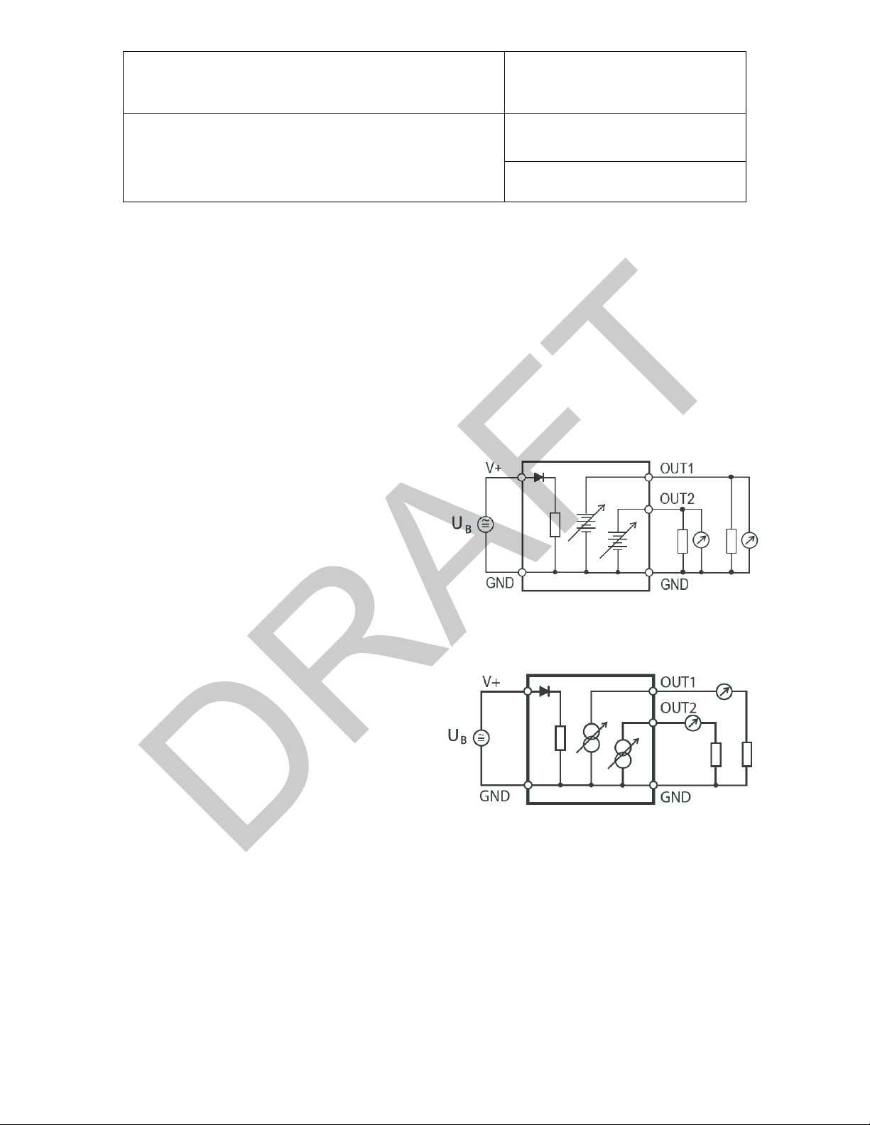
6.2.1 Electrical Diagrams
The HM4 is connected with the 7-pin Tuchel
connector or the connection cable with open ends.
The maximum permissible cable length depends
on the voltage drop caused by the flow of current
to the devices connected to the HM4 outputs. The
effective load of a HM4 output comprises the cable
and load resistance and should amount to at least
1000 Ω/V (for voltage outputs according to Figure
3). The cable resistance should not be more than
1/1000 of the load resistance.
Figure 3: Voltage outputs
The maximum permissible length of the cable
connecting the unit to other devices is determined
by the total resistance resulting from addition of
the cable resistance and resistance of the devices
connected to the unit in series. This resistance
should not exceed 500 ohm (load) (for current
outputs according to Figure 4).
Figure 4: Current outputs
© 2014; ROTRONIC AG E-M-HM4-V0_08
Page 24
E-M-HM4-V0_08
ROTRONIC AG
Bassersdorf, Switzerland
Document Code
Unit
HM4 Humidity and Temperature Probe with
Heated Sensor
Instruction Manual
Document Type
Page
24 of 41
Document Title
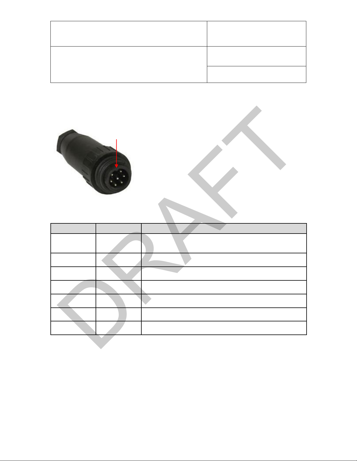
Pin
Name
Function
1
V (+)
5…24 VDC
15…24 VDC, depending on output variant and functions used
2
GND
Supply ground
3
AGND
Analog GND
4
OUT2, analog
Temperature (default setting: -40…60 °C)
5
RS-485 +
RS-485 TX+ / RX+
6
OUT1, analog
Humidity (default setting: 0…100 %RH)
7
RS-485 -
RS-485 TX- / RX-
Guide nose
1
2
3
4
567
DRAFT
6.3 Tuchel Connector Pin Configuration
The HM4 probe is available with Tuchel connector. It is connected either directly at the housing or remotely at
the end of a cable.
Figure 5: Tuchel connector and pin numbering
© 2014; ROTRONIC AG E-M-HM4-V0_08
Page 25

E-M-HM4-V0_08
ROTRONIC AG
Bassersdorf, Switzerland
Document Code
Unit
HM4 Humidity and Temperature Probe with
Heated Sensor
Instruction Manual
Document Type
Page
25 of 41
Document Title
Wire Colour
Name
Function
Green
V (+)
5…24 VDC
15…24 VDC, depending on output variant and functions used
Grey / Shield
GND
Supply ground
Yellow
AGND
Analog GND
Brown
OUT2, analog
Temperature (default setting: -40…60 °C)
Red
RS-485 +
RS-485 TX+ / RX+
White
OUT1, analog
Humidity (default setting: 0…100 %RH)
Blue
RS-485 -
RS-485 TX- / RX-
DRAFT
6.4 Cable Connection with Open Ends
© 2014; ROTRONIC AG E-M-HM4-V0_08
Page 26

E-M-HM4-V0_08
ROTRONIC AG
Bassersdorf, Switzerland
Document Code
Unit
HM4 Humidity and Temperature Probe with
Heated Sensor
Instruction Manual
Document Type
Page
26 of 41
Document Title
Output Variant
Load Resistance Specification
0…1 V
≥1 kΩ
0…5 V
≥5 kΩ
0…10 V
≥10 kΩ
0…20 mA
≤500 Ω
4…20 mA
≤500 Ω
DRAFT
7 Operation
7.1 Load Resistance Requirements of the Analog Outputs
Depending on the output variant, there are different limit values for the load resistance of the analog outputs.
© 2014; ROTRONIC AG E-M-HM4-V0_08
Page 27

E-M-HM4-V0_08
ROTRONIC AG
Bassersdorf, Switzerland
Document Code
Unit
HM4 Humidity and Temperature Probe with
Heated Sensor
Instruction Manual
Document Type
Page
27 of 41
Document Title
USB or TCP/IP
Master
HM4
240
240
Further RS-485 devices
DRAFT
7.2 RS-485 Interface
The HM4 has a serial RS-485 port. If the number of USB or TCP/IP network ports available is not enough, the
serial RS-485 interface can be used to connect up to 64 devices in a subnet (as shown in Figure 6). ROTRONIC
offers the RS-485 T-junction box AC3021 as suitable accessory for this.
To read out the measured values, it is also possible to access the HM4 directly without the HW4 software using
digital commands. See the manual E-M-AC3000-CP for the main AirChip3000 commands.
Important:
The RS-485 network address of an HM4 is factory set on "0". The integration of a new factory-configured RS485 device in an RS-485 network is performed by the HW4 software. The new device is identified by detection
of the address "0", which is then overwritten with the first free RS-485 address (i.e. the first address not yet used
in the network). This automatic mechanism prevents malfunctions from double allocation of addresses and use
of the invalid address "0" in the network.
ADD 1
Figure 6: Example of a RS-485 network with master (e.g.: HF5, HF8) and HM4.
Remarks:
The start and end of the bus line must both be terminated with a resistor of 240 Ω.
All devices must have the same baud rate of 19,200 baud (symbols/s).
It is possible to use a HF5, HF8, AC3011 cable (Ethernet-to-RS-485 converter) or AC3010 cable
(USB-to-RS-485 converter) as master in the RS-485 network.
The HF5 and HF8 must then be allocated a RS-485 address. The AC3011 and AC3010 cables do
not need a network address.
The HM4 cannot be supplied with power from the network; it needs a separate power supply of
15…24 VDC.
ADD n
© 2014; ROTRONIC AG E-M-HM4-V0_08
Page 28

E-M-HM4-V0_08
ROTRONIC AG
Bassersdorf, Switzerland
Document Code
Unit
HM4 Humidity and Temperature Probe with
Heated Sensor
Instruction Manual
Document Type
Page
28 of 41
Document Title
Parameter
Value
Baud rate
19,200
Parity
None
Data bits
8
Stop bits
1
DRAFT
All functions that can be set in the device with the HW4 software are described in the manuals E-M-
HW4v3-Main (points 6.4 and 7.5) and E-M-HW4v3-F2-022.
Only devices in the HygroClip2 generation may be interconnected in the RS-485 network. A mixed
network of HygroClip1 and HygroClip2 devices is not possible.
Other specifications of the RS-485 network:
© 2014; ROTRONIC AG E-M-HM4-V0_08
Page 29

E-M-HM4-V0_08
ROTRONIC AG
Bassersdorf, Switzerland
Document Code
Unit
HM4 Humidity and Temperature Probe with
Heated Sensor
Instruction Manual
Document Type
Page
29 of 41
Document Title
DRAFT
8 Maintenance
This chapter describes calibration, adjustment, validation and filter changes as well as the tools necessary for
this, e.g. service cable.
8.1 Service Cable
The following two service cables may be used for maintenance and calibration:
AC3010 (USB-to-RS-485 converter) for devices with open ends
AC3010-T (USB-to-RS-485 converter) for devices with Tuchel connector
The cables have an internal power feed of 5 VDC. This suffices for calibration, device settings and the sensor
heating (RoHumiHeat), but not for the cleaning function (RoHumiClean) and analog outputs greater than 0...1V.
Remark:
An AC3011 cable (Ethernet – RS-485 converter) can also be used.
© 2014; ROTRONIC AG E-M-HM4-V0_08
Page 30

E-M-HM4-V0_08
ROTRONIC AG
Bassersdorf, Switzerland
Document Code
Unit
HM4 Humidity and Temperature Probe with
Heated Sensor
Instruction Manual
Document Type
Page
30 of 41
Document Title
DRAFT
8.2 Calibration
Both the Pt100-RTD temperature sensor used in the probe and the corresponding electronics are very stable
and do not normally need to be calibrated after initial factory calibration. The long-term stability of the SMD
Thermo humidity sensor from ROTRONIC is normally better than 1 %RH per year. For maximum accuracy,
the calibration of the humidity probe should be checked every six to 12 months. Applications in which the
humidity probe is exposed to considerable contamination could require more frequent checks.
Start the HW4 software and look for the connected HM4 probes (HW4 Menu > Devices and Groups >
Search for Devices > Search for USB Master or Search for Ethernet Master)
The device tree of the HM4 lists all calibration and adjustment functions. The basic guidelines for
calibration and adjustment are described in the manual E-M-CalBasics.
Further instructions are to be found in the HM4 software manual E-M-HW4v3-A2-001.
IMPORTANT:
All heating and cleaning functions must be switched off during calibration and adjustment!
© 2014; ROTRONIC AG E-M-HM4-V0_08
Page 31

E-M-HM4-V0_08
ROTRONIC AG
Bassersdorf, Switzerland
Document Code
Unit
HM4 Humidity and Temperature Probe with
Heated Sensor
Instruction Manual
Document Type
Page
31 of 41
Document Title
DRAFT
8.3 Filter Maintenance
Depending on the application and environmental conditions, the filter must be checked from time to time and
cleaned or replaced when soiled.
1. Unscrew the filter from the probe housing and carefully pull the filter off the probe in a straight line.
2. When placing the filter back on again, take care not to damage or bend the wires of the Pt100 sensor
(Figure 7).
Figure 7: Probe head (filter removed)
8.4 Validation of the Analog Outputs
The HM4 offers the possibility to set the analog outputs on a fixed value. This makes it possible to test if the
output stages of the HM4 are working correctly. The function can be activated with the HW4 PC software. Setting
of fixed values is described in the manual E-M-HW4v3-F2-022.
© 2014; ROTRONIC AG E-M-HM4-V0_08
Page 32

E-M-HM4-V0_08
ROTRONIC AG
Bassersdorf, Switzerland
Document Code
Unit
HM4 Humidity and Temperature Probe with
Heated Sensor
Instruction Manual
Document Type
Page
32 of 41
Document Title
DRAFT
9 Firmware Update
The HM4 firmware can be updated with the HW4 software. Firmware updates are available for downloading on
the ROTRONIC website. They are written to the HM4 probe with an AC3010, AC3010-T or AC3011 service
cable.
IMPORTANT:
There must be a permanent connection to the computer and a stable power supply during the update process.
Procedure:
Connect the HM4 with one of the above-mentioned connection cables or devices.
Note:
As from 2014 the service cables have a standard USB driver. Older cables need a ROTRONIC
USB driver, which is installed on the PC together with the HW4 software. See the manual E-M-
HW4v3-Main for detailed information on the ROTRONIC USB driver.
Download the latest firmware to your PC from the ROTRONIC website.
Launch the HW4 software on the PC and look for the HW4 probe.
HW4 Main Menu > Devices and Groups > Search for Devices > Search for USB Master / Search
for Ethernet Master
Under Device Manager in the device tree, select Extras > Firmware Update
For further information, see the manual E-M-HW4v3-F2-023
© 2014; ROTRONIC AG E-M-HM4-V0_08
Page 33

E-M-HM4-V0_08
ROTRONIC AG
Bassersdorf, Switzerland
Document Code
Unit
HM4 Humidity and Temperature Probe with
Heated Sensor
Instruction Manual
Document Type
Page
33 of 41
Document Title
General
Device type
Humidity / Temperature probe
Circuit type
3-wire
Power Supply
(V+)
15…24 VDC (for all output variants and functions)
5…24 VDC (only 0…1 V analog output and sensor heating available)
Current consumption
<35 mA @ V+= 5 VDC (without sensor heating)
<55 mA @ V+= 5 VDC (with sensor heating)
<20 mA @ V+= 24 VDC (without sensor heating)
<30 mA @ V+ = 24 VDC (with sensor heating)
Electrical connection
Tuchel connector (7-pin) / Open ends
Polarity protection
Protective diode
Humidity Measurement
Sensor
SMD Thermo
Measurement range
0…100 %RH
Measuring accuracy @ 23 °C
±1.5 %RH (sensor heating switched on)
Extended measuring accuracy
±2.5 %RH @ 80 °C (sensor heating switched on)
±2.5 %RH @ 60 °C (sensor heating switched on)
±2.0 %RH @ 40 °C (sensor heating switched on)
±2.0 %RH @ 0 °C (sensor heating switched on)
±3.0 %RH @ -20 °C (sensor heating switched on)
±4.0 %RH @ -40 °C (sensor heating switched on)
Long-term stability
<1 %RH/year
Response time
Typically: 25 s (wind velocity at sensor: 1 m/s)
DRAFT
10 Technical Data
© 2014; ROTRONIC AG E-M-HM4-V0_08
Page 34

E-M-HM4-V0_08
ROTRONIC AG
Bassersdorf, Switzerland
Document Code
Unit
HM4 Humidity and Temperature Probe with
Heated Sensor
Instruction Manual
Document Type
Page
34 of 41
Document Title
Temperature Measurement
Sensor
Pt100 RTD, Class B 1/3 DIN
Measurement range
-40…85 °C, standard scale: -40…60 °C
Measuring accuracy @ 23 °C
±0.1 °C
Extended measuring accuracy
±0.1 °C @ -40…60 °C (sensor heating switched on)
±0.15 °C @ 60…85 °C (sensor heating switched on)
Long-term stability
<0.1 °C/year
Response time
Typically: 30 s, (wind velocity at sensor 1 m/s)
Calculated Parameters
Psychrometric calculations
Dew point (Dp) above and below freezing
Frost point (Fp) below freezing point and dew point above freezing point
Wet bulb temperature (Tw)
Enthalpy (H)
Vapour concentration (Dv)
Specific humidity (Q)
Mixing ratio by weight (R)
Vapour concentration at saturation (Dvs)
Vapour partial pressure (E)
Vapour saturation pressure (Ew)
Startup Time and Measurement Interval
Startup time
<9 s (typical)
Measurement interval
20 s (typical)
DRAFT
© 2014; ROTRONIC AG E-M-HM4-V0_08
Page 35

E-M-HM4-V0_08
ROTRONIC AG
Bassersdorf, Switzerland
Document Code
Unit
HM4 Humidity and Temperature Probe with
Heated Sensor
Instruction Manual
Document Type
Page
35 of 41
Document Title
Configurable Analog Outputs
Output 1
Can be assigned to every parameter
Default parameter
Humidity
Default range
Per order code
Output 2
Can be assigned to every parameter
Default parameter
Temperature
Default range
Per order code
Output 1 and output 2
Signal type
0…20 mA
4…20 mA
0…1 V
0…5 V
0…10 V
(user-configurable)
Accuracy analog output
±1.5 mV (voltage output, 0…1 V)
±15 mV (voltage output, 0…5/10 V)
±30 µA (current output, 0/4…20 mA)
Maximum offset at start of range
0…1 V : 1 mV
0…5 V : 10 mV
0…10 V : 10 mV
0…20 mA : 20 µA
4…20 mA : no offset
User-configurable range limits
-999 … +9,999 units
Refresh interval
20 s
Short circuit tolerant
Yes
Max. load
500 Ω (current output)
Min. load resistance
1 kΩ (voltage output, 0…1 V)
5 kΩ (voltage output, 0…5 V)
10 kΩ (voltage output, 0…10 V)
Resolution
16 Bit
DRAFT
© 2014; ROTRONIC AG E-M-HM4-V0_08
Page 36

E-M-HM4-V0_08
ROTRONIC AG
Bassersdorf, Switzerland
Document Code
Unit
HM4 Humidity and Temperature Probe with
Heated Sensor
Instruction Manual
Document Type
Page
36 of 41
Document Title
Digital Interface
Interface type
RS-485
Baud rate : 19,200
Parity : none
Data bits : 8
Stop bits : 1
Service Connector
Interface type
UART (TTL Level), inside housing
Max. length of service cable
5 m (16.4 ft)
Sensor Heating (RoHumiHeat)
Heating temperature
0.1…10 °C above ambient temperature
Operating modes
Permanent, time interval or value-dependent
Sensor Cleaning (RoHumiClean)
Heating temperature
To 150 °C
Operating modes
Programmable time interval
General Specifications
Probe material
POM (polyoxymethylene)
Filter material
Polyethylene, 20 µm pore size
Dimensions
238 x 29 mm (model with connector at housing)
281 x 25 mm, plus cable depending on order code (model with cable)
Weight
150 g (model with connector at housing)
Conformity with Standards
CE / EMC immunity
EMC Directive 2004/108/EC: EN 61000-6-1: 2007, EN 61000-6-2: 2005
EN 61000-6-3: 2007, EN 61000-6-4: 2007
Solder type
Lead free (RoHS directive)
Fire protection class
Corresponds to UL94-HB
FDA / GAMP directives
CFR21 Part 11 and GAMP5
DRAFT
© 2014; ROTRONIC AG E-M-HM4-V0_08
Page 37

E-M-HM4-V0_08
ROTRONIC AG
Bassersdorf, Switzerland
Document Code
Unit
HM4 Humidity and Temperature Probe with
Heated Sensor
Instruction Manual
Document Type
Page
37 of 41
Document Title
Environmental Limits
Operation
-40…85 °C / 0…100 %RH, non-condensing
Housing protection grade
IP65
Maximum wind velocity
20 m/s (7,870 ft /min), with filter
DRAFT
© 2014; ROTRONIC AG E-M-HM4-V0_08
Page 38
E-M-HM4-V0_08
ROTRONIC AG
Bassersdorf, Switzerland
Document Code
Unit
HM4 Humidity and Temperature Probe with
Heated Sensor
Instruction Manual
Document Type
Page
38 of 41
Document Title
DRAFT
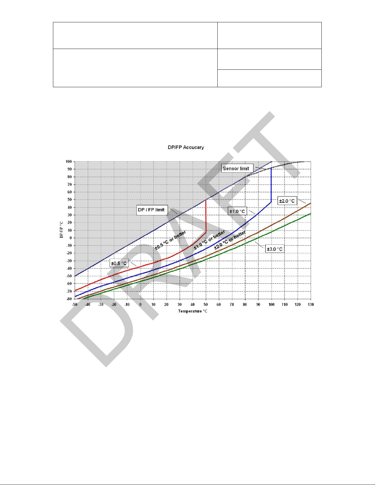
10.1 Dew Point Accuracy
The HM4 can be configured to calculate the dew point on the basis of the measurement of the relative humidity
and temperature. The accuracy of this conversion varies depending on the humidity and temperature conditions
as shown in Figure 8:
Figure 8: Dependency of the accuracy of dew point calculation from the measured humidity and temperature
values
Example:
At a temperature of 20 °C, a dew point value between -27 °C and 20 °C is calculated with an accuracy of
±0.5 °C or better.
© 2014; ROTRONIC AG E-M-HM4-V0_08
Page 39

E-M-HM4-V0_08
ROTRONIC AG
Bassersdorf, Switzerland
Document Code
Unit
HM4 Humidity and Temperature Probe with
Heated Sensor
Instruction Manual
Document Type
Page
39 of 41
Document Title
Order Code
Description
AC3010
USB/RS-485 converter with
open line ends. Allows
connection of the RS-485 lines
of the HM4 probe to the USB
port of a PC. The HM4 then
works as slave in an RS-485
network.
AC3010-T
USB/RS-485 converter with
Tuchel socket. Allows
connection of the RS-485
interface of the HM4 probe (with
Tuchel connector) to the USB
port of a PC. The HM4 then
works as slave in an RS-485
network.
Tuchel socket
USB connector
(Type A)
USB
connector
(Type A)
Open line ends
DRAFT
11 Accessories
All accessories for ROTRONIC products are to be found in the manual E-M-HC2-accessories. The most
important connection cables for HM4 probes are shown below:
© 2014; ROTRONIC AG E-M-HM4-V0_08
Page 40

E-M-HM4-V0_08
ROTRONIC AG
Bassersdorf, Switzerland
Document Code
Unit
HM4 Humidity and Temperature Probe with
Heated Sensor
Instruction Manual
Document Type
Page
40 of 41
Document Title
Document Name
Contents
E-M-HC2-accessories
Accessories such as service cables, calibration accessories, filters for
probes, transmitters
E-T-AC3000-DF-V1
AirChip3000, description and main functions
E-M-HW4v3-DIR
List of all HW4 manuals
E-M-HW4v3-Main
HW4 software version 3: general instructions and description of
functions
E-M-HW4v3-F2-023
HW4 software version 3:
HM4 humidity and temperature probe, device configuration, data
handling
E-M-HW4v3-A2-001
HW4 software version 3: device adjustment, overview of functions of
AirChip3000 devices
E-M-AC3000-CP
AirChip 3000 communication protocol options
E-M-CalBasics
Adjustment principles for humidity and temperature adjustment
E-T-HumiDefs
Humidity definitions
DRAFT
12 Additional Documents
Remark:
The full document names are followed by the respective version numbers. These version numbers were omitted
in the above table.
© 2014; ROTRONIC AG E-M-HM4-V0_08
Page 41

E-M-HM4-V0_08
ROTRONIC AG
Bassersdorf, Switzerland
Document Code
Unit
HM4 Humidity and Temperature Probe with
Heated Sensor
Instruction Manual
Document Type
Page
41 of 41
Document Title
Version
Date
Remark
V0_08
May 2014
Release document
DRAFT
13 Document Versions
© 2014; ROTRONIC AG E-M-HM4-V0_08
 Loading...