


IN-E-HL-NT-V2_15
Document code Unit
Rotronic AG
Bassersdorf, Switzerland
HygroLog HL-NT data logger:
instruction manual
Document title
HygroLog HL-NT Data Logger
Instruction Manual
Instruction Manual
Document Type
Page
1 of 74
© 2009-2015; Rotronic AG IN-E-HL-NT-V2_15

IN-E-HL-NT-V2_15
Document code Unit
Rotronic AG
Bassersdorf, Switzerland
HygroLog HL-NT data logger:
instruction manual
Document title
Instruction Manual
Document Type
Page
2 of 74
Table of contents:
Overview.................................................................................................................................. 4
1.
1.1 General ................................................................................................................................ 4
1.2 Compatibility with previous models of probes and docking stations ................................... 6
2. General description of the HygroLog HL-NT ....................................................................... 7
2.1 Models ................................................................................................................................. 7
2.2 Required accessories .......................................................................................................... 8
2.3 HygroLog HL-NT inputs ....................................................................................................... 9
2.4 Power supply ..................................................................................................................... 12
2.5 Memory card ...................................................................................................................... 14
2.6 LED Indicators ................................................................................................................... 15
2.7 Beeper ............................................................................................................................... 15
2.8 HygroLog HL-NT functions ................................................................................................ 16
2.9 HygroClip 2 probe functions .............................................................................................. 21
2.10 Event tracking .................................................................................................................... 21
2.11 Operating limits (electronics only) ..................................................................................... 25
3. Docking stations for the HygroLog HL-NT ........................................................................ 26
3.1 Models ............................................................................................................................... 27
3.2 Installation .......................................................................................................................... 32
3.3 Relay contacts ................................................................................................................... 39
4. Pin-out diagrams .................................................................................................................. 40
5. HW4 software ........................................................................................................................ 43
5.1 Computer/Operating System Requirements ..................................................................... 43
5.2 Operating System Compatibility ........................................................................................ 44
5.3 Settings and functions acces sible only with HW4 ............................................................. 45
6. ERES regulatory compliance .............................................................................................. 47
7. Getting started ...................................................................................................................... 48
8. Stand-alone operation ......................................................................................................... 48
8.1 Operating modes ............................................................................................................... 48
8.2 Display and keypad ........................................................................................................... 49
8.3 Display modes ................................................................................................................... 51
8.4 Settings and functions accessible from the Keypad .......................................................... 52
8.5 Internal function menu (models with display and keypad)................................................. 53
9. Operation on a network ....................................................................................................... 59
9.1 Baud rate and communications protocol compatibility requirements ................................ 59
9.2 Ethernet local area network ............................................................................................... 60
9.3 RS-485 multi-drop network ................................................................................................ 61
9.4 General wiring guidelines .................................................................................................. 63
9.5 Guidelines for RS-4 85 w ir in g ............................................................................................. 64
10. HygroClip probe adjustment procedures ..................................................................... 65
10.1 Single Point adjustment ..................................................................................................... 65
10.2 Multi-Point adjustment ....................................................................................................... 67
11. Warnings and useful tips ................................................................................................ 67
12. Communications protocol .............................................................................................. 68
13. Firmware updates ............................................................................................................ 68
14. Specifications .................................................................................................................. 69
15. Accessories ...................................................................................................................... 72
16. Supporting documents ................................................................................................... 73
17. Document releases .......................................................................................................... 74
© 2009-2015; Rotronic AG IN-E-HL-NT-V2_15

IN-E-HL-NT-V2_15
Document code Unit
Rotronic AG
Bassersdorf, Switzerland
HygroLog HL-NT data logger:
instruction manual
Document title
Instruction Manual
Document Type
Page
3 of 74
Applicability:
This manual is va lid for inst rum ents with firm ware version 2.0x (see MENU - Instrument or check
using the ROTRONIC HW4 software, Device Manager). Examples: 2.0a, 2.0b. Changes in the last
character of the ver sion number reflec t minor changes in the intern al software of the instr ument
that do not affect the manner in which the instrument should be operated.
© 2009-2015; Rotronic AG IN-E-HL-NT-V2_15

IN-E-HL-NT-V2_15
Document code Unit
Rotronic AG
Bassersdorf, Switzerland
HygroLog HL-NT data logger:
instruction manual
Document title
Instruction Manual
Document Type
Page
4 of 74
1. Overview
1.1 General
HygroLog HL-NT is a series of networkable data loggers primarily designed for use with the
HygroClip 2 digital humidity-temperature probes.
Depending on the model and options, the HygroLog HL-NT main features are as follows:
o Internal probe input: allows installing a HC2-S humidity-temperature probe internally to
prevent unauthori zed removal. T his input can also be c onnected to an external pr obe by
means of an extension cable.
o Inputs for up to 6 a dditional exter nal probes , including analog probes and 4-wire pass ive
RTD probes.
o Monitoring of up to two external contacts (relay output, door, etc.).
o Large recording capacity with removable flash memory card. Up to 750,000 values can be
recorded with the standard 64 MB card. Cards with a capacity of up to 1 GB are available.
o Display with backlight and keypad. This allows the HygroLog HL-NT to operate as a stand-
alone unit after initial configuration with the HW4 software.
o Compliance with F DA 21 CF R Part II and G AMP r egulat ions r egardin g elec tronic rec ords
and electronic signatures (ERES).
o Compatible with Ethernet networks (TCP / IP protocol – LAN or WLAN).
o Dedicated RS-485 network of up to 64 HygroLog HL-NT per communication port
o Simultaneous data recording and data display either locally or on a PC.
Internal power for both the HygroLog HL-NT and probes is provided by a 9V battery (factory
standard) or by a 9V rechargeable battery (user supplied).
The HygroLog HL-NT requires a docking station to (a) to power the HygroLog HL-NT with an
external AC adapter, (b) to configure the HygroLog HL-NT and comm unicate with a PC, (c) to
connect the HygroLo g HL-NT to a network and (d) to m ount the HygroLog H L-NT to a wall or to
place the HygroLog HL-NT on the optional desk-top stand.
© 2009-2015; Rotronic AG IN-E-HL-NT-V2_15

IN-E-HL-NT-V2_15
Document code Unit
Rotronic AG
Bassersdorf, Switzerland
HygroLog HL-NT data logger:
instruction manual
Document title
Instruction Manual
Document Type
Page
5 of 74
The most basic m odel of doc k ing station s im ply pro vides a m eans of m ountin g the HygroLog HLNT to a wal l and of poweri ng the H ygroLog HL-NT with an ext ernal AC adapter. All o ther m odels
offer the same f unctionality as the basic model and also pro vide a communicatio n port (RS232,
USB or RJ45 / Eth ernet) as well as addi tional inputs for probes and external contacts . Docking
stations with an RS232 or USB port are used to connect the H ygroLog HL-NT directl y to a PC.
Docking stations with an RJ45 connector are used to connect the HygroLog HL-NT to an Ethernet
LAN. In both cases, the docking station features an RS485 port that can be us e d to c onnect up to
64 HygroLog HL-NT i n a multi-dropped ar rangement (ded icated RS-485 net work). This is usef ul
when the PC does not have a n Ethernet ne twork inter face card or when the number of a vailable
Ethernet ports is lim ited. Direct connection to an Ethernet LAN allows, in pr inciple, an unlimited
number of HygroLog HL-NT to be put on a ne twork monitored b y the HW 4 software. HW 4 allo ws
any combination of RS-232, USB, Ethernet and RS-485 connections.
When equipped with a docking station, the HygroLog HL-NT can be used together with the
ROTRONIC HW4 software for Windows based PCs (version 2.3.0 or higher). In addition to
providing for the net working of large quantities of dat a loggers and other instrum ents, the main
functions of HW4 include:
o Configuration of the HygroLog HL-NT and docking station
o Programming of the HygroLog HL-NT logging function
o Manual or automatic downloading of the data recorded by the HygroLog HL-NT
o On-line data monitoring and direct data recording by the PC
o Automatic generation of graphs and data tables
o Monitoring of the networked instruments and data for alarm conditions
o Alarm reporting
o Maintenance of audit trails
o Calibration and adjustment of the HygroClip 2 probes
o Generation of protocols, electronic signatures, etc.
A high level of protectio n agai nst net work failures c an be ac hieved by log ging dat a direc tl y on the
PC while also recording t he data locally on the H ygroLog HL-NT with automat ic download to the
PC at regular interval of times.
Note: Instructions for using the HW 4 software are not included in this m anual. These ins tructions
are shipped separately on the software CD ROM.
© 2009-2015; Rotronic AG IN-E-HL-NT-V2_15

IN-E-HL-NT-V2_15
Document code Unit
Rotronic AG
Bassersdorf, Switzerland
HygroLog HL-NT data logger:
instruction manual
Document title
Instruction Manual
Document Type
Page
6 of 74
1.2 Compatibility with pr e vi ous m ode ls of probes and docking stations
o The HygroLog HL-NT is designed for use with the H ygroClip 2 probes (UART interface)
and is not compatible with the previous generation of HygroClip probes (DIO interface).
o Docking stations designed f or the previous ge neration of HygroClip pro bes (such as DS-
U1, DS-U4, etc.) are not compatible with the HygroLog HL-NT.
o RS-485 drop-down networks: the HygroLog HL-NT is compatible with previous versions of
the HygroLog NT and with other legacy products. The HygroLog HL-NT cannot be used in
the same RS-485 drop-down as a HF4 or HF5 transmitters or any product that rely on the
RO-ASCII communications protocol.
o Unlike previous versions, The HygroLog HL-NT does not have a remote mode
© 2009-2015; Rotronic AG IN-E-HL-NT-V2_15

IN-E-HL-NT-V2_15
Document code Unit
Rotronic AG
Bassersdorf, Switzerland
HygroLog HL-NT data logger:
instruction manual
Document title
Instruction Manual
Document Type
Page
7 of 74
2. General description of the HygroLog HL-NT
2.1 Models
Basic models without display and keypad
o HygroLog HL-NT2: lo gger for plug-in HygroClip 2 pr obe (probe is not included and must
be ordered separat ely). Probe model HC2-S can be m ounted either internally or in the
extended position. Other probe models are external and require an extension cable.
o HygroLog HL-NT3: same as HL-NT2 with 2 additional connectors suitable for a HygroClip2
digital probe.
Models with display and keypad
o HygroLog HL-NT2-D: same probe as HygroLog HL-NT2
o HygroLog HL-NT3-D: same probe / probe inputs as HygroLog HL-NT3
Models with internal HC2-S probe pre-installed
o Models HL-NT2-P, HL-NT2-DP, HL-NT3-P and HL-NT3-DP are supplied with an internal
HC2-S probe pre-installed.
© 2009-2015; Rotronic AG IN-E-HL-NT-V2_15

IN-E-HL-NT-V2_15
Document code Unit
Rotronic AG
Bassersdorf, Switzerland
HygroLog HL-NT data logger:
instruction manual
Document title
Instruction Manual
Document Type
Page
8 of 74
2.2 Required accessories
● Models without display/keypad:
The following accessories are required in order to be able to use the logger:
- Any model of docking station (except model DS-NT1)
- Connecting cable docking station to PC
- PC with the ROTRONIC HW4 software installed (version 2.3.0 or higher)
● Models with display/keypad:
In principle, these models can be used without any accessory. However, accessing all of the
product functions and cha nging some important s ettings such as the date and tim e requires the
same accessories as for the models without display.
© 2009-2015; Rotronic AG IN-E-HL-NT-V2_15

IN-E-HL-NT-V2_15
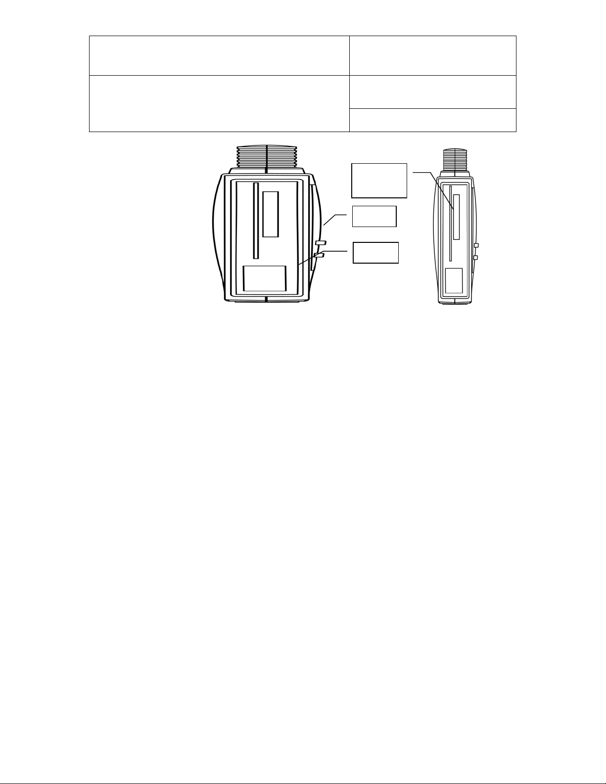
To open the housing of the
HygroLog, remove the
screws
arrows.
The
drawing shows
the HygroClip S probe in the
retracted position. The base
o
a connector that is
separated from the main
board by a length of wire.
Probe
connector
The shorter screw
Document code Unit
Rotronic AG
Bassersdorf, Switzerland
HygroLog HL-NT data logger:
instruction manual
Document title
Instruction Manual
Document Type
Page
9 of 74
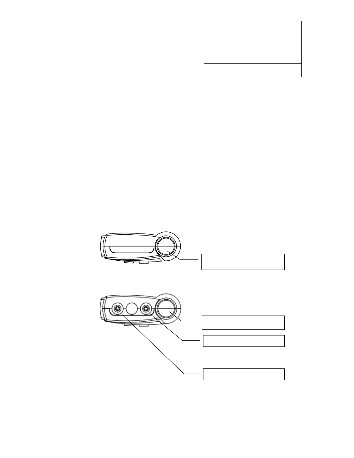
2.3 HygroLog HL-NT inputs
2.3.1 Probe input 1
HygroLog HL-NT2-P, HL-NT2-DP, HL-NT3-P and HL-NT3-DP: these models are supplied with
an internal HC2-S plug-in probe. T his probe can be either retracted or extended. T he probe can
also be separated from t he logger with an ex te ns io n cable, a nd i n this case the HC2-S pr ob e may
be replaced with another model of HygroClip 2 probe so as to meet specific application
requirements (see document E-M-HC2 Probes-V1). Open the housing of the HygroLog to change
the position of the probe or to install a probe extension cable.
five
, as indicated by the
far right
f the probe is plugged into
To extend the pro be, lif t the H ygroClip S probe f rom its position a nd rem ove the slotted cap from
the HygroLog. To extend the probe, place on the probe the ring supplied with the HygroLog. Insert
the ring into the s lot in the instrument housing wher e the slotted cap was. Reloc ate the probe
connector up b y one or two ribs. Close the instrument housing. Proceed in a sim ilar manner to
install a probe extension cable.
© 2009-2015; Rotronic AG IN-E-HL-NT-V2_15
goes here

IN-E-HL-NT-V2_15
HygroClip S
Extension cable used to
Ring
Document code Unit
Rotronic AG
Bassersdorf, Switzerland
HygroLog HL-NT data logger:
instruction manual
Document title
extended position
(replaces the slotted cap)
Instruction Manual
Document Type
Page
10 of 74
separate the probe from
the HygroLog.
© 2009-2015; Rotronic AG IN-E-HL-NT-V2_15
IN-E-HL-NT-V2_15
Input 1 (HygroClip 2 probe)
Input 2 (HygroClip 2 probe)
Input 3 (HygroClip 2 probe)
Input 1 (HygroClip 2 probe)
HL-NT2
HL-NT3
Document code Unit
Rotronic AG
Bassersdorf, Switzerland
HygroLog HL-NT data logger:
instruction manual
Document title
Notes:
o For maximum protection against vandalism, use the HC2-S probe in the retracted position.
For a faster response, use the probe in the extended position.
o For additional information on the HygroClip 2 probes see document
E-M-HC2 Probes-V1.
Instruction Manual
Document Type
Page
11 of 74
2.3.2 Probe inputs 2 and 3 (HygroLog HL-NT3)
The HygroLog HL-NT3 can be used with up to 2 additional HygroClip 2 probes. For further
information on the HygroClip 2 probes, see document E-M-HC2 Probes-V1.
2.3.3 Connector identification
© 2009-2015; Rotronic AG IN-E-HL-NT-V2_15

IN-E-HL-NT-V2_15
Document code Unit
Rotronic AG
Bassersdorf, Switzerland
HygroLog HL-NT data logger:
instruction manual
Document title
Instruction Manual
Document Type
Page
12 of 74
2.4 Power supply
The HygroLog HL-NT ships with a r egular 9V battery which must be inser ted first (see battery
replacement).
To conserve battery po wer, models wit h the LC displa y and keypad are s hipped with the D isplay
Sleep function enabled (s ee Software Fu nctions). W hen the keypad has n ot been used for some
time, this function au tomatic ally turns of f the disp lay off . The displa y can be tem poraril y activ ated
by pressing on any key of the keypad.
When connected to a dock ing station, the H ygroLog HL-NT can be po wered with an external AC
adapter.
Note: most models of docking station require the use of an external AC adapter due to the current
consumption of the docking station internal electronics.
After reconfiguring the HygroLog HL-NT with the ROTRONIC HW4.software, a rechargeable
battery (accumulator ) can be used instead of a regu lar battery. Rechargi ng the battery require a
docking station and an external AC adapter.
WARNING: Trying to recharge a regular battery is potentially danger ous. Whenever a regular
battery is being used, the logger should be configured with the internal battery charge
function disabled.
© 2009-2015; Rotronic AG IN-E-HL-NT-V2_15

IN-E-HL-NT-V2_15
Rechargeable
Rechargeable
Regular
Regular
1 Probe / 5s Interval
2.7
3.4
11
22
1 Probe / 5s Interval / LCD
2.1
2.6
8.9
17
1 Probe / 1min Interval
14
17
59
118
1 Probe / 1min Interval / LCD
5.8
7.3
24
48
1 Probe / 15min Interval
89
111
372
744
1 Probe / 15min Interval / LCD
8.9
11
37
74
Document code Unit
Rotronic AG
Bassersdorf, Switzerland
HygroLog HL-NT data logger:
instruction manual
Document title
Instruction Manual
Document Type
Page
13 of 74
2.4.1 Battery lifetime
The battery lifetim e depends on the manner in which th e HygroLog HL-NT is being used. The
HygroLog HL-NT has a battery lifetim e of one year wh en just one HygroC lip probe is be ing used
(standard 500 mAh alkaline battery), when no docking station with internal electronics is connected
to the HygroLog HL-NT and when the logger is configured / programmed as follows:
• Display Sleep function enabled (models with display)
• No docking station with internal electronics
• LED and beeper functions disabled
• Log interval set to 15 minutes
Additional examples of battery lifetime (LED turned off, Logging active): in the following table, LCD
means that the LC display is permanently on (Display Sleep function disabled). No docking station
with internal electronics is connected to the HygroLog HL-NT.
Lifetime in days
Note: the consumption of the display is negligible when the Display Sleep function is enabled. With
the display always on, power consumption is at its highest when the display refresh rate is set with
HW4 to the minimum of 5 sec.
Because of the requirement to keep track of the date and time, the HygroLog HL-NT does not have
Battery
120mAh
Battery
150mAh
Battery
500mAh
Battery
1000mAh
a power on/off switch. Every minute, both the date and time are recorded to the internal EEPROM.
Seconds are not rec orded. In the event of a relatively brief interruption of po wer (such as when
replacing the battery), t im e may fall behin d in incr em ents of one minute. Rem oving the batt ery for
an extended period of time will cause the logger to completely lose track of the date and time.
© 2009-2015; Rotronic AG IN-E-HL-NT-V2_15

IN-E-HL-NT-V2_15
cover
To access the
remove the screw shown
to the right and open
rubber cover.
The
the bottom
instrument
battery
Document code Unit
Rotronic AG
Bassersdorf, Switzerland
HygroLog HL-NT data logger:
instruction manual
Document title
2.4.2 Battery replacement
battery,
the
battery is located at
of the
.
2.5 Memory card
Instruction Manual
Document Type
Page
14 of 74
The HygroLog HL-NT has a non-volatil e 64 kb EEPROM internal memory that is used to s av e the
logger configuration data, the logger events and to temporarily hold measurement data.
The main memor y is a plug-in f lash m em ory card. As a standard, the H ygroLo g HL-NT ships with
a 64 MB card. This card allows the recording of up to 400,000 values in text file format (unprotected)
or up to 750,000 values in bin ary file f ormat ( protected) . Mem ory cards with a c apacit y of up to 1
GB can be purchased f rom third parties. Regardless of its size, the flash memory card ho lds a
maximum of 512 files and directories, including one logger-configuration and one logger-event file.
The measurem ent data c an be s av ed ei ther to a file with exte ns ion X L S or to a file with extension
LOG. Files with XLS exten sion can be read with Note pad or imported into Micro soft Excel. Files
with extension LOG are encoded in binary format so as to prevent data manipulation and can only
be read with the RO TRO NIC HW4 software. Both t ypes of f iles can c o-exis t on t he m em or y card.
The memory card ca n be rem oved from the logger an d transf erred to a car d reader, a PDA, etc .
The flash memory card can also be read without being removed from the logger.
© 2009-2015; Rotronic AG IN-E-HL-NT-V2_15
IN-E-HL-NT-V2_15
cover
memory
Memory Card:
To access the memory
card,
shown to the right and pull
out the rubber cover.
The plug
card is located
the main board.
screw
Document code Unit
Rotronic AG
Bassersdorf, Switzerland
HygroLog HL-NT data logger:
instruction manual
Document title
card
remove the screw
-in flash memory
on top of
Instruction Manual
Document Type
Page
15 of 74
2.6 LED Indicators
The HygroLog HL-NT is equipped with a green and red LED. The logger can be conf igured with
HW4 to have the green side of the LE D f las h when lo ggi ng is act ive. The red side of t he LE D c a n
be made to flash when there is an a larm condition (see note below) and / or when the logger
requires attention (low battery, flash memory card full, etc.)
In the transient alarm mode, the red LED flashes for only as long as the data from a probe
corresponds to an alarm condition. In the durable alarm mode, the red LED stays on even after the
alarm condition has dis appeared. When the LED is set to prov ide a dura ble al arm, it c an be rese t
from the keypad or with HW4.
2.7 Beeper
The HygroLog HL-NT is equipped with an internal beeper and can be configured with HW4 to make
a clicking so und when an y key is being pres sed. The beep er can also be c onfigured to em it a 5second non-repeating s ound when ther e is an alarm cond ition and / or when t he logger requires
attention.
© 2009-2015; Rotronic AG IN-E-HL-NT-V2_15

IN-E-HL-NT-V2_15
Document code Unit
Rotronic AG
Bassersdorf, Switzerland
HygroLog HL-NT data logger:
instruction manual
Document title
Instruction Manual
Document Type
Page
16 of 74
2.8 HygroLog HL-NT functions
2.8.1 Calculated parameter
Using the HW 4 software, the HygroLog HL-NT can be set t o compute for eac h HygroClip probe
one of the following psychrometric parameters.
o Dew point (Dp)
o Frost point (Fp)
o Wet bulb temperature (Tw)
o Enthalpy (H)
o Vapor concentration (Dv)
o Specific humidity (Q)
o Mixing ratio by weight (R)
o Vapor concentration at saturation (Dvs)
o Vapor partial pressure (E)
o Vapor saturation pressure (Ew)
Each individual probe input can be associated with a different parameter.
Note: depending on whether dew point or f ros t po int w as s elec t ed, bot h t he HygroLog HL-NT and
HW4 will displa y either t he symbol Dp or the s ymbol Fp for values belo w freezing. The s ymbol Fp
indicates that the va lue is a frost point as op posed to being a de w point. Regardless of the dew
point / frost point selection, the symbol Dp is always displayed for values above freezing.
Some of the above parameters require barometric pressure as an input. When an analog pressure
probe is connected to one of the HygroLog HL-NT inputs, the logger can be set to use the
measurement fr om this pro be. When no pressure prob e is b ein g used, a fixed press ure val ue c a n
be used. This value can be specified as part of the HygroLog HL-NT settings.
© 2009-2015; Rotronic AG IN-E-HL-NT-V2_15

IN-E-HL-NT-V2_15
Document code Unit
Rotronic AG
Bassersdorf, Switzerland
HygroLog HL-NT data logger:
instruction manual
Document title
Instruction Manual
Document Type
Page
17 of 74
2.8.2 Data logging
Data logging requires that a flash memory card be inserted inside the logger. Using the HW4
software, log files can be set to one of the following formats:
• H W4 binary format [LOG]: files in this format are encoded and can be opened only with the
ROTRONIC HW 4 software. HW 4 does not al low an y manipulat ion / alter ation of the data
and requires a pass word to log in. Should the file be som ehow modif ied, HW 4 will give a
warning that the file is not an original.
• Text file format [XLS]: in principle, files in th is format can be opened with an y text editor
and / or imported into Microsoft Excel.
The log fil e form at is a glob al setting of the f lash memor y card (cha nging th is setting r equires the
HW4 software). At any gi ven time, the card records data f r om all inputs i n eit her o ne f ormat or the
other. Files of diff erent f orm ats can co-exist in the flash m emor y card. Binar y files (protec ted) us e
substantially less memory space than text files (unprotected).
The logging func tion is independently activated for each individual input. The HygroLog HL-NT
creates a separate fil e for e ach in put that is to be recor ded. Mu ltiple in puts can not be recorde d to
the same file. The H ygroLo g HL-NT automatical l y generates each f ile nam e. A f ile nam e c onsists
of 8 digits followed by the extension LOG or XLS. The first 4 digits are the same as the last 4 digits
th
of the logger serial number, the 5
digit is the same as the input number and the last 3 digits are a
number between 000 and 999 used to dif ferentiate log files created for the sam e input. The last
number that was created is retained in the non-vo lat il e EEPRO M an d is u pda ted when ev er a n e w
file is created for the input. When the number reaches 999, the next update will reset it to 000.
All files are located in the r oot directory of the f lash memory card, includ ing the logger event f ile
and the logger conf iguration file. R egardless of the memor y card capacit y, the root directory is
limited to a maxim um of 250 files. T his m eans that the m emor y card can hold a m aximum of 248
log files, and that a card with this amount of files is considered to be full, even if all the memory has
not been used.
© 2009-2015; Rotronic AG IN-E-HL-NT-V2_15

IN-E-HL-NT-V2_15
Document code Unit
Rotronic AG
Bassersdorf, Switzerland
HygroLog HL-NT data logger:
instruction manual
Document title
Using HW4, the following log settings can be defined individually for each input:
• Start date and time
• Stop date and time
• Log interval (minimum 5 seconds)
• Measured values and computed parameter, or any parameter combination
• User custom text (used for the log file header)
• User name, HW4-ID, HW4 Serial Number
• Automatic creation of a new file after 200,0 00 d ata p o ints or at th e end of each day, week
or month
Note: unlimited logging (loop mode logging) is not possible. Logging stops automatically when the
flash memory card is full. Prior to logging, th e user may use HW 4 to check the amount of fr ee
Instruction Manual
Document Type
Page
18 of 74
memory, and verify that there is enough room available.
If the flash memor y card is removed when logging is ac tive, the HygroLog HL-NT will stop logging
until a new card is inserted. Un less the stop date and time hav e been reached, logging will s tart
again under the next available file name when a new card is inserted.
Warning: removing the m emory card while lo gging is active m ay result in a corrupted log f ile and
in loss of data.
Logging can be started im mediatel y for any individua l input fr om the ke ypad of the HygroLo g HLNT. A deferred start can only be programmed with the HW4 software. The green LED of the
HygroLog HL-NT can be set to f lash when the i nstrument is recording data. T o conserve batter y
power, you may want to do this only when an external power source is being used.
Logging can be imm ediately stopped f or any indi vidual inpu t directl y from the keypad. W ith HW4,
logging can be stopped either imm ediately or at a fut ure date and tim e for any individua l input or
for all inputs.
When logging is ended, the HygroLog HL-NT returns to the measuring mode.
© 2009-2015; Rotronic AG IN-E-HL-NT-V2_15

IN-E-HL-NT-V2_15
Document code Unit
Rotronic AG
Bassersdorf, Switzerland
HygroLog HL-NT data logger:
instruction manual
Document title
Instruction Manual
Document Type
Page
19 of 74
2.8.3 Trend indicators
See also: Main operating modes and measurement interval
When the trend indic ator f u nction is ena bled, a s ymbol app ears o n th e left side of the LC d ispla y,
on the line corresponding to each measured or calculated value. An up arrow denotes a rising value
and a down arrow denotes a decreasing value. Both arrows denote a stable value.
The trend of a parameter is evaluated by comparing successive averages made of 6 values each.
With the shortest possible measurement interval of 5 seconds, each average covers a time period
of 30 seconds and th e first indication of a trend is availab le after one m inute. Subsequently, th e
trend is evaluated and updated every 30 seconds. With a longer measurement interval, each
average is computed over a longer p eriod of time (alwa ys using 6 values) and the trend is also
updated over longer intervals of time.
For any measured or c a lc ul ated par ameter, the trend i ndicat or s ho ws a s tab le co ndit io n w hen th e
absolute value of the difference between two successive averages is < 0.02.
2.8.4 Alarm function
Using the HW4 sof tware, both a high an d a low a larm value ca n be associ ated with the humidit y,
temperature and calculated parameter of each probe input, A hysteresis value can also be entered
for each parameter. This value is used for both the low and the high alarm conditions.
The HygroLog HL-NT has a red LED which ca n be set with HW 4 to flash when ever the value of
any parameter corresponds to an alarm condition. The LED can be set to flash only as long as the
alarm condition exits or it can be s et to provide a durable alarm and, in this case, it will to keep
flashing until the alarm is reset.
The HygroLog HL-NT can also be se t with HW4 to beep for 5 seconds when there is an alarm
condition. The HygroLog HL-NT will beep only once, when the condition occurs.
Log files do not recor d the exis tence of an a larm cond ition. However, when the c ontents of a log
file are viewed as a data table with the HW4 software, values that correspond to an alarm condition
© 2009-2015; Rotronic AG IN-E-HL-NT-V2_15

IN-E-HL-NT-V2_15
Document code Unit
Rotronic AG
Bassersdorf, Switzerland
HygroLog HL-NT data logger:
instruction manual
Document title
Instruction Manual
Document Type
Page
20 of 74
are printed over a red bac kground, based on the a larm settings that HW 4 downloaded from the
logger.
2.8.5 Display-Sleep function
This function can be enabled and configured only with the HW4 software.
Using the Display Sleep f unction can substantially extend the lif etime of the battery. When the
Display Sleep f unction is ac tive, the LC display of the HygroLog H L-NT stays blank . The Display
Sleep function is effective both in the measure and in the record mode.
The display of the HygroLog HL-NT can be set to be always on. It can also be set to automatically
go blank af ter 30 seconds , 1, 5, 1 0 or 20 minutes when no k ey is bein g pressed or when there is
no communication with a P C. If t he H ygroCli p NT was in the function menu at the time the display
goes blank, it automatically exits the menu.
The HygroLog suspends the Display Sleep function whenever a key is pressed. The f unction is
also suspended when ext ernal power is available or when the logger receives a communication
1
request (for exam ple from a PC
). When the displ ay comes up again, it shows by defau lt the
measurements from the probe that was selected last.
1
When the HygroLog HL-NT is connected by means of a docking station to a PC and HW4
is running, you should use an external AC adapter to power both the HygroLog HL-NT and
docking station. HW4 can be set to use a polling i nte r val as s hort as 5 s econds to interrogate al l
instruments connected to the PC and this could cause the battery life time to be sharply reduced.
© 2009-2015; Rotronic AG IN-E-HL-NT-V2_15

IN-E-HL-NT-V2_15
Document code Unit
Rotronic AG
Bassersdorf, Switzerland
HygroLog HL-NT data logger:
instruction manual
Document title
Instruction Manual
Document Type
Page
21 of 74
2.9 HygroClip 2 probe functions
2.9.1 Simulator function (validation of the signal transmission):
If so desired, transm ission of the HC2 pr obe output signals c an be validated b y using the probe
simulator function. T he HW4 s oftwar e is r equir ed to en able and conf igur e this f unc tion. When the
function is enabled the probe generates digital and analog signals corresponding to values
specified by the user.
2.9.2 Sensor failure detection and fail safe mode:
The HygroClip 2 probe aut omatically detects a sensor failure such as a shorted or open sensor.
This information is passed to both the HygroLog HL-NT and HW4 software. The optional display of
the HygroLog H L-NT will show an alar m message. The H ygroC lip 2 pr o be c an al s o be configured
with the HW4 software to generate a "safe or readily identifiable" fixed value for humidity and
temperature in the event of a shorted or open sensor.
Note: the sensor diagnostics and drift compensation function of the HygroClip 2 probe is not
available with the HygroLog HL-NT due t o the fact that the probe is powered on ly briefly during
each log or measurement interval.
2.10 Event tracking
The HygroLog HL-NT maintains an internal event file with the extension EVT. This function is
always enabled.
Part of the procedure to ensure conformity to the FDA requirements is to use the HW4 software to
disable the MENU key on the HygroLog HL-NT keypad. The MENU key is the only key that can be
used to make c hanges to t he Hygr oLog HL-NT. When this proce dure is implem ented, th e events
recorded by the HygroLog HL-NT are the result of an interaction with the HW4 software. When the
MENU ke y i s not disable d, a l imited number of events ar e rec orded in the logger eve nt file. In this
case no entries are made in the logger event file header. The two tables below provide a list of the
events tracked by the HygroLog HL-NT.
© 2009-2015; Rotronic AG IN-E-HL-NT-V2_15

IN-E-HL-NT-V2_15
The battery was inserted or the instrument powered down and up
Writing device
While recording data, the logger could not find the memory card. The
The memory card was replaced while data was being logged. The
Document code Unit
Rotronic AG
Bassersdorf, Switzerland
HygroLog HL-NT data logger:
instruction manual
Document title
Instruction Manual
Document Type
Page
22 of 74
The logger event file is spli t bet ween the internal memory of the logger ( up to 1 70 even ts ) and the
flash memory card (practically unlimited number of events). HW4 offers the possibility of
downloading, open ing and print ing the ent ire file conte nts. All pas t logger eve nts are ava ilable to
HW4 as long as t he flas h m emory card is not rem oved f rom the lo gger. T he serial number of the
logger is used as the file name.
Example: 1111111111.EVT
The logger event file consists of a file header and a file body. The file header provides the following
information:
o Most recent programming of the log function: programming date and time, user and HW4
product ID
o Most recent device configuration: date and time, user and HW4 product ID
o Most recent adjustment to the PC date and time: date and time, user and HW4 product ID
An individual record with date and time is enter ed in the e vent file bod y for each indi vidual event
listed in the two tables below:
Interaction with the HW4 software:
Event Description
Power up
after an internal problem
Watchdog overflow Internal instrument error (normally should not occur)
New or existing configuration written to logger
configuration
Memory card removed
data was written to the EEPROM and are not yet lost
Memory card full No free memory space on the memory card
New memory card
data will be split between two different memory cards. Possibly,
inserted
some data has been lost.
© 2009-2015; Rotronic AG IN-E-HL-NT-V2_15

IN-E-HL-NT-V2_15
Logging stopped
Logging ended
Out-of-limits value
The battery is empty and the logger has powered itself off (keeping
Beginning accumulator
Accumulator charge
Lost data, memory
While recording data, the logger could not find the memory card. The
HygroClip probe
HygroClip probe
A HygroClip probe was removed from input # or the input can no
External power
External power
The A/C adapter was disconnected, or failed, or is not being
Device time changed /
Device date and time prior and after adjustment (up to firmware
Document code Unit
Rotronic AG
Bassersdorf, Switzerland
HygroLog HL-NT data logger:
Instruction Manual
instruction manual
Document title
Page
Event Description
Humidity adjusted Humidity adjustment of the probe connected to input #
Temperature adjusted Temperature adjustment of the probe connected to input #
Logging started Start recording data from input #
Data recording of input # ended before the programmed stop time
manually
Data recording of input # ended at the programmed stop time
automatically
An out-of-limits value was newly detected on input #
detected
Battery almost empty Battery voltage dropped below 6.5V
23 of 74
Document Type
Battery empty
charge
ended
MFG command
card not ready
connected 1
disconnected 1
connected
removed or faulty
power up could result in erroneous data or loss of data)
Starting to charge the rechargeable battery
Rechargeable battery full
Reserved for the factory
data could not be written to the EEPROM, and was lost
A HygroClip probe was connected to input #
longer communicate with the probe
The A/C adapter was connected and is being powered
powered
adjusted
v1.1d only)
Prior device time Device date and time prior to change (firmware v1.2a and up)
© 2009-2015; Rotronic AG IN-E-HL-NT-V2_15

IN-E-HL-NT-V2_15
RS-485 address
Docking station
The docking station was disconnected or there is no longer any
Docking station
A docking station was connected and communication was
Logger language file
A different internal language file was loaded or the same file was
Log function
Logging stopped
Log function
Document code Unit
Rotronic AG
Bassersdorf, Switzerland
HygroLog HL-NT data logger:
Instruction Manual
instruction manual
Document title
Page
Event Description
New device time Device date and time after change (firmware v1.2a and up)
The RS-485 address was changed
changed
EEPROM erased
disconnected 2
connected 2
downloaded
Reserved for the factory
communication with it
established
loaded again
The log function has been programmed for input #
programmed
24 of 74
Document Type
Event file deleted
1
connection / removal of analog probes is not recorded
2
only when the docking station has internal electronics
Reserved for the factory
Events triggered from the keypad:
Event Description
Humidity adjusted Humidity adjustment of the probe connected to input #
Temperature adjusted Temperature adjustment of the probe connected to input #
Logging started Start recording data from input #
Data recording of input # ended before the programmed stop time
manually
Prior device time Device date and time prior to change (firmware v1.2a and up)
New device time Device date and time after change (firmware v1.2a and up)
programmed
The log function has been programmed for input #
© 2009-2015; Rotronic AG IN-E-HL-NT-V2_15

IN-E-HL-NT-V2_15
Document code Unit
Rotronic AG
Bassersdorf, Switzerland
HygroLog HL-NT data logger:
instruction manual
Document title
Instruction Manual
Document Type
Page
25 of 74
2.11 Operating limits (ele c tr onics only)
Models without display:
● -10…50°C with the factory supplied alkaline battery
● -30…70°C with a lithium battery or an external AC adapter
Models with display:
● -10…50°C with the factory supplied alkaline battery
● -10…60°C with a lithium battery or an external AC adapter
The HygroClip probes have generally wider operating limits (see individual probe specifications).
© 2009-2015; Rotronic AG IN-E-HL-NT-V2_15

IN-E-HL-NT-V2_15
Document code Unit
Rotronic AG
Bassersdorf, Switzerland
HygroLog HL-NT data logger:
instruction manual
Document title
Instruction Manual
Document Type
Page
26 of 74
3. Docking stations for the HygroLog HL -NT
The HygroLog HL-NT requires a docking station with the appropriate interface to be able to
communicate with a PC with the RO TRONIC HW4 software inst alled. The connector located on
the back of the HygroLog HL-NT is meant to be used with one of the available docking stations
(UART interface). When installed on a PC, the ROTRONIC HW4 software is used to configure the
HygroLog HL-NT, to program its logging function, to download the recorded data and to adjust the
probes connected to the logger against a reference environment.
A docking station is required for any of the following:
o Mount the HygroLog HL-NT to a wall
o Place the HygroLog on the optional desk-top stand
o Use an external AC adapter to power the HygroLog HL-NT
o Connect the HygroLog HL-NT to a PC: RS232 or USB port, Ethernet (TCP/IP) LAN
or WLAN
o Connect up to 64 H ygroLog HL-NT or other devices together in a m ulti-dropped network
(RS-485)
Depending on the model, using a docking station also adds functionality to the HygroLog HL-NT:
o Up to 4 additional probes, including analog probes and direct 4-wire RTDs
o Logical inputs (external contacts)
o Relay outputs
Note: docking stations with internal electronics and PC interf ace should b e ge ner a l ly use d with an
external AC adapter.
© 2009-2015; Rotronic AG IN-E-HL-NT-V2_15

IN-E-HL-NT-V2_15
Document code Unit
Rotronic AG
Bassersdorf, Switzerland
HygroLog HL-NT data logger:
instruction manual
Document title
Instruction Manual
Document Type
Page
27 of 74
3.1 Models
All models of docking st ation have the same physical dimensions an d can be used either as a
mechanical adapter to plac e the HygroLog HL-NT on t he option al desk -top stand or as a bracket
to mount the HygroLog HL-NT to a wall. Docking stations are available in the following
configurations:
3.1.1 Basic docking stations (no digital interface)
o HL-DS-NT0: basic docking station without internal electronics. This model simply provides
a means of mounting the HygroLog HL-NT to a wall
o HL-DS-NT1: basic dock ing station without internal electronic s (similar to m odel HL-DS-
NT0). This model simply provides a receptacle for an AC adapter used to power the
HygroLog HL-NT
3.1.2 Docking stations with RS-232 serial interface
o HL-DS-NT2: receptacle for AC adapter, one serial port (RS232) and one RS485 port (multi-
drop).
o HL-DS-U1: receptacle f or AC adapter, one serial (R S232) port, one RS485 port (m ulti-
drop), four probe inputs (HygroClip 2 or analog probe with 0…2.5 V signal), one connector
for up to two logical input signals.
© 2009-2015; Rotronic AG IN-E-HL-NT-V2_15

IN-E-HL-NT-V2_15
Document code Unit
Rotronic AG
Bassersdorf, Switzerland
HygroLog HL-NT data logger:
instruction manual
Document title
Instruction Manual
Document Type
Page
28 of 74
3.1.3 Docking stations with USB interface
o HL-DS-NT3: receptacle for AC adapter, one USB port and one RS485 port (multi-drop).
o HL-DS-U2: receptacle f or AC adapter, one USB port, one RS485 port (m ulti-drop), four
probe inputs (HygroClip or analog probe with 0…2.5 V signal), one connector for up to two
logical input signals.
o HL-DS-U2-420: same as HL-DS-U2 but designed for analog probes with a 4…20 mA
output signal. Each probe input uses an internal 150 Ohm resistor to convert 4…20 mA to
600…3000 mV (nominal).
o HL-DS-PT2: receptacle for AC adapter, one USB port, one RS485 port (multi-drop
networking), four con nectors f or RTD probe (dir ect 4-wire con nection), one c onnector f or
up to two logical input signals.
o HL-DS-R1: receptacle for AC adapter, one USB port, one RS485 port (multi-drop
networking), one conn ector for up to two logical inp ut signals and t wo independent r elay
output connectors.
© 2009-2015; Rotronic AG IN-E-HL-NT-V2_15

IN-E-HL-NT-V2_15
Document code Unit
Rotronic AG
Bassersdorf, Switzerland
HygroLog HL-NT data logger:
instruction manual
Document title
Instruction Manual
Document Type
Page
29 of 74
3.1.4 Docking stations with wired Ethernet interface
Note: with an y of the follow ing models, use an exte nsion cable to s eparate all probes from either
the HygroLog HL-NT or docking station s o as to av oid m easur ement err ors due to s elf -heating b y
the docking station.
o HL-DS-NT4: receptacle for AC a dapter, one RJ 45 connector (Ethernet) , one RS 485 port
(multi-drop) and one connector for up to two logical input signals.
o HL-DS-NT4-WEB: same as HL-DS-NT4 but with an internal web server that can be
accessed with a web browser.
Note: Probe adjustment is not possible with WEB docking stations.
o HL-DS-U4: receptacle f or AC adapter, one RJ45 connector (Ethernet), one RS485 port
(multi-drop), four probe inputs (HygroClip or analog probe with 0…2.5 V signal), one
connector for up to two logical input signals.
o HL-DS-U4-WEB: same as HL-DS-U4 but with an internal web server that can be accessed
with a web browser.
Note: Probe adjustment is not possible with WEB docking stations.
o HL-DS-U4-420: same as HL-DS-U4 but designed for analog probes with a 4-20 mA output
signal. Each probe input uses an internal 150 Ohm resistor to convert 4…20 mA to
600…3000 mV (nominal).
o HL-DS-U4-420-WEB: same as HL-DS-U4-420 but with an internal web server that can be
accessed with a web browser.
Note: Probe adjustment is not possible with WEB docking stations.
o HL-DS-PT4: receptac le for AC adapter, on e RJ45 connector (Et hernet), one RS485 p ort
(multi-drop networking), two connectors for RTD probe (direct 4-wire connection), one
connector for up to two logical input signals.
© 2009-2015; Rotronic AG IN-E-HL-NT-V2_15

IN-E-HL-NT-V2_15
Document code Unit
Rotronic AG
Bassersdorf, Switzerland
HygroLog HL-NT data logger:
instruction manual
Document title
Instruction Manual
Document Type
Page
30 of 74
3.1.5 Docking stations with wireless Ethernet interface
Note: with any of the follow ing models, use an exte nsion cable to s eparate all probes from either
the HygroLog HL-NT or docking station s o as to av oid m easur ement err ors due to s elf -heating b y
the docking station.
o HL-DS-NT4-WL: receptacle f or AC adapter, WLAN trans ceiver, one RS485 port (m ulti-
drop) and one connector for up to two logical input signals.
o HL-DS-U4-WL: receptacle for AC adapter, WLAN transceiver, one RS485 port (multi-
drop), two probe inputs (HygroClip 2 or analog probe with 0…2.5 V signal), one connector
for up to two logical input signals.
o HL-DS-U4-WEB-WL: same as HL-DS-U4-WL but with an interna l web s erver that c an be
accessed with a web browser.
Note: Probe adjustment is not possible with WEB docking stations.
o HL-DS-PT4-WL: receptacl e for AC adapter, WLAN transceiver, on e RS485 port (multi-
drop networking), two connectors for RTD probe (direct 4-wire connection), one connector
for up to two logical input signals.
© 2009-2015; Rotronic AG IN-E-HL-NT-V2_15
IN-E-HL-NT-V2_15
Network Interface – Wireless LAN
Standard
IEEE 802.11b
Frequency
2.4 GHz
Data Rate
Up to 11 Mbps with automatic fallback
Modulation
CCK (11/5.5 Mbps), DQPSK (2 Mbps), DBPSK (1 Mbps)
Typical Transmit Power
16 dBm
Receive Sensitivity
-52 dBm @ 11 Mbps
Connector
1 x RP-5MA
WLAN Security
WEP (Wired Equivalent Privacy)
64 / 128-bit encryption (RCA)
WPA / WPA2 / 802.11i
128-bit TKIP/CCMPA (AES) encryption
Document code Unit
Rotronic AG
Bassersdorf, Switzerland
HygroLog HL-NT data logger:
instruction manual
Document title
o
Instruction Manual
Document Type
Page
31 of 74
Note: The WLAN security of docking station HL-DS-U4-WEB-WL (with internal web browser) is
limited to WEP with 64-bit encryption (no WPA).
Enterprise mode (802.1X); LEAP (WEP only), PEAP,
TTLS, TLS; EAP-FAST, GTC, MD5, OTP, PAP, CHAP,
MSCHAP, MSCHAP
, TTLS-MSCHAPV2
V2
Pre-shared key mode (PSK/Personal)
© 2009-2015; Rotronic AG IN-E-HL-NT-V2_15

IN-E-HL-NT-V2_15
To mount the docking station to a wall, use
the two holes shown on the right
HygroLog
docking station
To attach the HygroLog NT to the
so as to match the
to prevent removal
[B]
[B]
[A]
Document code Unit
Rotronic AG
Bassersdorf, Switzerland
HygroLog HL-NT data logger:
instruction manual
Document title
3.2 Installation
Installation is the same for all models of docking station.
. The
NT can then be attached to the
as explained below.
Instruction Manual
Document Type
Page
32 of 74
docking station:
Place the HygroLog NT on the
docking station
two areas [A]. Press lightly one
against the other and secure the
assembly with threaded pin [B].
When the docking station is
mounted on a wall, a small
padlock (not shown) may be put
through pin [B]
of the HygroLog NT from the
docking station.
© 2009-2015; Rotronic AG IN-E-HL-NT-V2_15

IN-E-HL-NT-V2_15
Probe input 4
Probe input 5
Logical inputs
Probe input 6
Probe input 7
RS-485
12VDC Power
RS-232
Probe input 4
Probe input 5
Probe input 6
Probe input 7
RS-485
12VDC Power
(+) center
USB
Logical inputs
Document code Unit
Rotronic AG
Bassersdorf, Switzerland
HygroLog HL-NT data logger:
instruction manual
Document title
3.2.1 Connector identification
HL-DS-U1
(HC2 / 0…2.5 V)
(HC2 / 0…2.5 V)
Instruction Manual
Document Type
Page
(HC2 / 0…2.5 V)
(HC2 / 0…2.5 V)
33 of 74
(+) center
HL-DS-U2
(HC2 / 0…2.5 V)
(HC2 / 0…2.5 V)
(HC2 / 0…2.5 V)
(HC2 / 0…2.5 V)
© 2009-2015; Rotronic AG IN-E-HL-NT-V2_15

IN-E-HL-NT-V2_15
Probe input 4
Probe input 5
Logical inputs
Probe input 6
RJ45
RS-485
12VDC Power
Probe input 7
Probe input 4
Probe input 5
Probe input 6
Probe input 7
RS-485
12VDC Power
USB
Logical inputs
Document code Unit
Rotronic AG
Bassersdorf, Switzerland
HygroLog HL-NT data logger:
instruction manual
Document title
HL-DS-U2-420
(HC2 / 0(4)…20 mA)
(HC2 / 0(4)…20 mA)
(+) center
Instruction Manual
Document Type
Page
34 of 74
(HC2 / 0(4)…20 mA)
(HC2 / 0(4)…20 mA)
HL-DS-U4
(HC2 / 0…2.5 V)
(+) center
(HC2 / 0…2.5 V )
(HC2 / 0…2.5 V )
(HC2 / 0…2.5 V )
© 2009-2015; Rotronic AG IN-E-HL-NT-V2_15

IN-E-HL-NT-V2_15
Probe input 4
Logical inputs
Probe input 6
Antenna
RS-485
12VDC Power
Probe input 4
Probe input 5
Logical inputs
Probe input 6
RJ45
RS-485
12VDC Power
Probe input 7
Document code Unit
Rotronic AG
Bassersdorf, Switzerland
HygroLog HL-NT data logger:
instruction manual
Document title
HL-DS-U4-420
(HC2 / 0(4)…20 mA)
Instruction Manual
Document Type
Page
(HC2 / 0(4)…20 mA)
(HC2 / 0(4)…20 mA)
35 of 74
(+) center
HL-DS-U4-WL
(HC2 / 0…2.5 V )
(HC2 / 0(4)…20 mA)
(HC2 / 0…2.5 V )
(+) center
© 2009-2015; Rotronic AG IN-E-HL-NT-V2_15

IN-E-HL-NT-V2_15
Input 4: RTD
Binder ET-409
Input 5: RTD
Binder ET-409
Logical inputs
Input 6: RTD
Input 7: RTD
RS-485
12VDC Power
USB
Input 4: RTD
Logical inputs
Input 6: RTD
RJ45
RS-485
12VDC Power
(+) center
Document code Unit
Rotronic AG
Bassersdorf, Switzerland
HygroLog HL-NT data logger:
instruction manual
Document title
HL-DS-PT2
Connector type:
Binder ET-409
Connector type:
Binder ET-409
Instruction Manual
Document Type
Page
Connector type:
Connector type:
36 of 74
(+) center
HL-DS-PT4 / HL-DS-PT4-WL
Connector type:
Binder ET-409
or WLAN
Connector type:
Binder ET-409
© 2009-2015; Rotronic AG IN-E-HL-NT-V2_15

IN-E-HL-NT-V2_15
Contact material
Silver alloy
Initial contact resistance
100 mΩ
Initial insulation resistance
Min. 1,000 MΩ at 500V DC
Nominal switching capacity 1)
2 A 250 VAC
Minimum switching power 1)
1,500 VA
Maximum switching voltage 1)
250 V AC
Maximum switching current 1)
2 A AC
Minimum switching capacity 1)
100 mA, 5 V DC
Expected life (min. operations)
Mechanical: 5 x 10⁶
Relay 1
Not used
Logical Inputs
Relay 2
Not used
RS-485
12VDC Power
(+) center
USB
Document code Unit
Rotronic AG
Bassersdorf, Switzerland
HygroLog HL-NT data logger:
instruction manual
Document title
HL-DS-R1
Instruction Manual
Document Type
Page
37 of 74
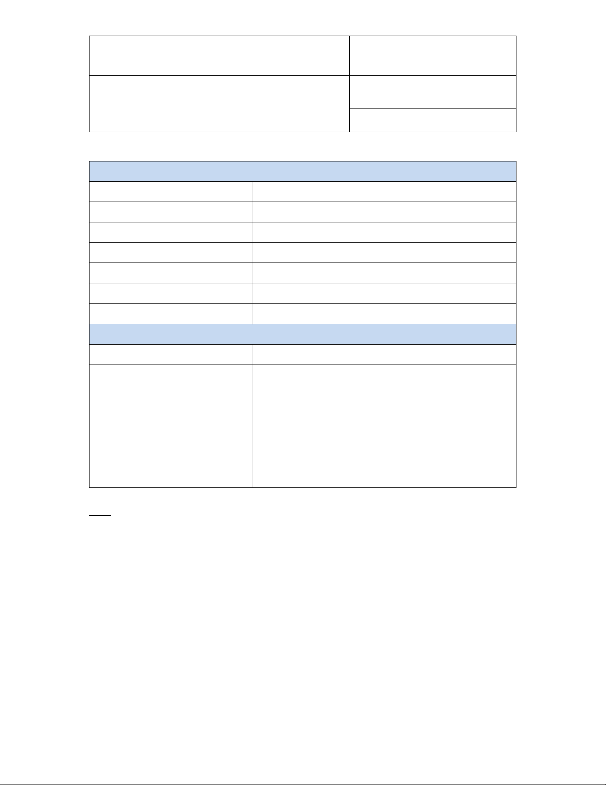
The relay contacts are specified as follows:
Electrical: N.O. 5 x 10⁴
4
N.C. 3 x 10
1) Resistive
The DS-R-1 docking stat ion is provided with two matching 4-pin connectors. The pins of thes e
connectors are numbered on the connector solder side (see pin-out diagrams).
Docking station inputs:
Depending on the m odel of docking station, the signals from up to 4 additional probes can be
processed by the HygroLog HL-NT.
© 2009-2015; Rotronic AG IN-E-HL-NT-V2_15

IN-E-HL-NT-V2_15
Document code Unit
Rotronic AG
Bassersdorf, Switzerland
HygroLog HL-NT data logger:
instruction manual
Document title
Instruction Manual
Document Type
Page
38 of 74
3.2.2 HygroClip 2 probes
By default inputs 4, 5, 7 and 7 of d ocking stat ions HL-DS-U1, HL-DS-U2, HL-DS-U4 and HL-DSU4-WL are c onfigured by the factory to accept a HygroClip 2 probe. An y model of HygroClip 2
probe can be connected these using one of the available extension cables. See document
E-M-HC2-accessories.
3.2.3 1-channel analog probes with voltage output
Inputs 4, 5, 7 and 7 of docking stations HL-DS-U1, HL-DS-U2, HL-U4 and HL-DS-U4-WL can also be
configured to accept one of the following:
o 1-channel analog probe: To be compatible with the docking station the analog probe must meet
the following requirem ents: s upply volta ge: 5 VDC , curr ent consum ption: max . 10 m A, output
signal: 0 to max. 3.3 VDC. The docking station uses a 12-bit A/D converter to digitize the probe
analog signal and can be configured to measure practically any parameter.
o Analog pressure probe: this is a special case of analog probe and is subject to the same
compatibility requirements. When analog pressure probe is selected, any input of the HygroLog
HL-NT and doc king station can be configured to use the signal f rom the pressure probe to
calculate any humidity parameter that requires barometric pressure as an input value (example:
mixing ratio).
3.2.4 1-channel analog probes with current output
Docking station HL-DS-U4-420 is similar to doc king station HL-DS-U4 with the difference that it
accepts up to four 3-wire single channel analog probes with a 4-20 mA current output signal. Each
probe input uses an in ternal 150 O hm resis tor to convert 4… 20 mA to 600… 3000 m V (nominal).
The HW4 software allows a 2-point adjustment of the mA to mV conversion to compensate for the
tolerance on the 150 Ohm resistor (use Device Manager in HW4). The probes are powered by the
docking station (supply voltage: 5 VDC, maximum current draw: 10 mA / probe).
© 2009-2015; Rotronic AG IN-E-HL-NT-V2_15

IN-E-HL-NT-V2_15
Document code Unit
Rotronic AG
Bassersdorf, Switzerland
HygroLog HL-NT data logger:
instruction manual
Document title
Instruction Manual
Document Type
Page
39 of 74
3.2.5 Pt100 RTD 4-wire probes
Docking stations HL-DS-PT2, HL-DS-PT4 and HL-DS-PT4-WL are designed for 4-wire RTD
probes. These docking stations allow the measurement of temperature conditions within the range
of -100 to 600°C. Accuracy depends on the class of the Pt100 RTD. Adjustment of the RTD inputs
against a reference temperature is limited to a 1-point adjustment (global offset).
3.2.6 Logical inputs (on / off)
Several models of doc king station allow the H ygroLog HL-NT to proces s up to 2 logical inp uts.
Typically this is used to monitor a relay contact, a door contact, etc.
3.3 Relay contacts
Docking station model HL-DS-R1 features two independent relays, each with 3 contacts: normally
closed, normally open a nd common. When conf iguring the HygroLog HL-NT and doc king station
with the HW4 software, a number of conditions can be defined that will cause the relay to be either
energized or de-energized.
The relays of the HL-DS-R1 docking station can be used to provide a local indication of the
following:
o Out of limit values for probe inputs 1 to 3 of the HygroLog HL-NT
o Status of the two logical inputs of the DS-R-1 docking station
o Memory card error
o External power failure
o Low battery charge
© 2009-2015; Rotronic AG IN-E-HL-NT-V2_15

IN-E-HL-NT-V2_15
HygroClip 2 probe
7: TXD (UART)
Analog 1-channel probe
7: not used
Document code Unit
Rotronic AG
Bassersdorf, Switzerland
HygroLog HL-NT data logger:
instruction manual
Document title
Instruction Manual
Document Type
Page
40 of 74
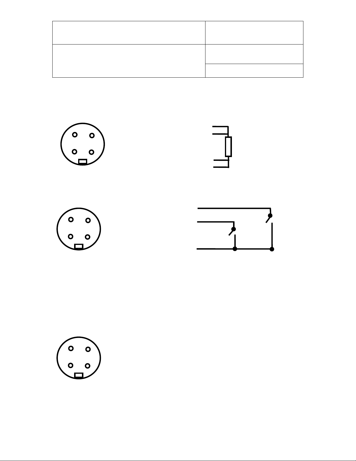
4. Pin-out diagrams
Note: all pin-out diagrams are shown from the solder side of the matching connector
• HygroLog HL-NT2 and HL-NT3: the probe inputs are always configured for a HygroClip2
probe
• Dock ing s tati ons HL-DS-U1, HLDS--U2, HL-DS-U4, HL-DS-U4-420 and HL-DS-U4-WL: the
probe inputs can be configured for either a HygroClip 2 probe or for a 1-chann el ana log prob e
1: RXD (UART)
2: GND (digital and power)
3: V+ (nominal 3.3 VDC)
4: not used
5: not used
6: not used
1: not used
2: GND (analog and power)
3: V+ (nominal 5 VDC, maximum 10 mA)
4: not used
5: not used
6: analog signal (0.0…3.3 VDC or 4…20 mA
© 2009-2015; Rotronic AG IN-E-HL-NT-V2_15
IN-E-HL-NT-V2_15
1: DC (+)
1 2 3
4
4-wire RTD
4
3
2
1 4 3
2
1
1: + 3.5 VDC
1
2
GND: not used (eventually use for a shield)
+3.5 V
Note: an internal pull-down resistor sets
3
4 1 2
1: Normally closed (relay de-energized)
Document code Unit
Rotronic AG
Bassersdorf, Switzerland
HygroLog HL-NT data logger:
instruction manual
Document title
• Docking stations HL-DS-PT2, HL-DS-PT4 and HL-DS-PT4-WL:
direct Pt100 RTD (Bi nder ET-409 connector)
2: measurement (+)
3: measurement (-)
4: DC (-)
• Docking stations with logical inputs (Binder ET-409 connector)
Instruction Manual
Document Type
Page
41 of 74
2: Input 1
3: Input 2
4: GND
each input to 0 when the contact is open.
Logical Thresholds: logical 1: ≥ 2.8 VDC, logica l 0: ≤ 0.7 VDC
• Docking station HL-DS-R1 with relay outputs (Binder ET-409 connector)
2: Common
3: Normally open
4: Not used
© 2009-2015; Rotronic AG IN-E-HL-NT-V2_15

IN-E-HL-NT-V2_15
1: 485 (-)
4
3 2 1
Note: use pins 3 and 4 to power multi-dropped instruments with a single external 12 VDC
Pin #
RS-232
2
TX 3 RX 5 GND
1 5 6
9
Document code Unit
Rotronic AG
Bassersdorf, Switzerland
HygroLog HL-NT data logger:
Instruction Manual
instruction manual
Document title
• Docking stations with RS-485 port (Binder ET-409 connecotr)
2: 485 (+)
3: GND (see note)
4: DC + (see note)
power supply with adequate mA rating. Pin 4 and the 12VDC power jack of the docking
station are not connected.
• Docking stations with RS-232 port
Page
42 of 74
Document Type
© 2009-2015; Rotronic AG IN-E-HL-NT-V2_15

IN-E-HL-NT-V2_15
Document code Unit
Rotronic AG
Bassersdorf, Switzerland
HygroLog HL-NT data logger:
instruction manual
Document title
Instruction Manual
Document Type
Page
43 of 74
5. HW4 software
The HygroLog HL-NT requires a docking station with the appropriate interface to be able to
communicate with a PC with the ROTRONIC HW4 software installed (version 2.3.0 or higher).
Detailed instructions are prov ided in the HW 4 manual s (see Suppor ting docum ents at the e nd of
this manual).
The HW4 instruction manuals are available on the HW4 installation CD and can also be
downloaded from our web site.
5.1 Computer/Operating Sy s t e m Requirements
The following are the m inimum values require d to install a nd run HW 4 on a c omputer . It is highl y
recommended to exceed these values.
o Processor: Pentium II, 450 MHz
o RAM: 128 MB
o Available hard disk space: 50 MB
o Monitor: SVGA, 1024 x 768, 256 colors
o Ports: one free serial (COM) port or one free USB port or Network Interface Card / Ethernet LAN
with one free port (RJ45 connector)
© 2009-2015; Rotronic AG IN-E-HL-NT-V2_15

IN-E-HL-NT-V2_15
Document code Unit
Rotronic AG
Bassersdorf, Switzerland
HygroLog HL-NT data logger:
instruction manual
Document title
Instruction Manual
Document Type
Page
44 of 74
5.2 Operating System Compat ibility
o Windows XP, NT4 with SP 6a or higher, Vista
o Windows 2000 with SP 2 or higher
o Windows Server 2003
HW4 was written for the Microsoft .NET framework (version 2.0) and requires this framework to be
installed on the computer.
The .NET framework offers significant improvements in the areas of networking and user security.
When new software is being installed, the .NET framework also eliminates the potential problem of
conflicting dynamic library files (DLL). Acc ordi ng to Microsoft, the .NET f r am ework will b e us e d by
all future Microsoft operating systems.
© 2009-2015; Rotronic AG IN-E-HL-NT-V2_15

IN-E-HL-NT-V2_15
Document code Unit
Rotronic AG
Bassersdorf, Switzerland
HygroLog HL-NT data logger:
Instruction Manual
instruction manual
Document title
Page
45 of 74
5.3 Settings and functions acc e s sible only with HW4
Device configuration settings
• User specific information (retained in the logger)
• Custom text associated with the logger (30-character descr ipti on)
• Network address of the logger
• Language used in the logger menu
• Date and time format / separators
• Decimal symbol
• Pressure unit (English) and mixed unit systems
• Individual input settings:
o Probe type (HygroClip 2 or analog) – docking station only
o Probe / input description (maximum 12 characters)
o Parameter to be calculated for an individual input
Document Type
o Barometric pressure: fixed value or read from an input
o Value to be used as fixed barometric pressure
o Alarm settings for humidity, temperature and calculated parameter
• ● Display settings:
o Display refresh rate
o Turn display off after xx minutes (display sleep function)
• Backlight operation
• Alternate the display - automatically show all inputs one after the other
• Keypad disable functions:
o Disable entire keypad
o Disable only the MENU key
• Type of internal power source: standard battery or rechargeable battery
• LED and Sound settings
• Cancel a latching alarm (LED on logger and/or de-energizing optional docking station
relays)
• Memory card settings: log file format and memory management
• Programming of the optional inputs (docking station)
© 2009-2015; Rotronic AG IN-E-HL-NT-V2_15

IN-E-HL-NT-V2_15
Document code Unit
Rotronic AG
Bassersdorf, Switzerland
HygroLog HL-NT data logger:
instruction manual
Document title
Data recording functions
• Logging functions (set individually for each input, can be scheduled for a future date / time):
o Start date and time
o Stop date and time
o Log measured values and computed parameter, or any combination
o Custom text (used for the log file header - up to 43 characters)
o User name, HW4-ID, HW4-serial number (used for the log file header)
o Automatic creation of a new file after 200,000 data points or at the end of each
day, week or month
• Global programming of the log function of all inputs
• Data downloading (from the logger) and associated functions
HygroClip 2 probe functions
Instruction Manual
Document Type
Page
46 of 74
• Device Manager (probe configuration settings, simulator function, fail safe mode)
• Data recording (at the probe level)
• Probe calibration and adjustment (full functionality)
For detailed instructions, see the following HW4 software manuals:
o E-M-HW4v3-F2-013: Device Manager – HygroLog HL-NT data logger
o E-M-HW4v3-F2-001: Device Manager – HC2 probe series
o E-M-HW4v3-A2-001: Probe Adjustment function AirChip 3000 devices
o E-M-HW4v3-DR-001: Data Recording Function AirChip 3000 Devices
© 2009-2015; Rotronic AG IN-E-HL-NT-V2_15

IN-E-HL-NT-V2_15
Document code Unit
Rotronic AG
Bassersdorf, Switzerland
HygroLog HL-NT data logger:
instruction manual
Document title
Instruction Manual
Document Type
Page
47 of 74
6. ERES regulatory compliance
In order to comply with ERES regulatory requirements (Electronic Records and Electronic
Signatures), the H ygroLog HL-NT should be used together with th e ROTRON IC HW4 software –
Professional Edition (version 2.3.0 or higher). HW4 is designed to keep track of logger configuration
changes, programming changes and of any probe adjustment. HW4 also keeps track of user events
(main operations performed by each user) and self-events (software problems). The records
generated by HW4 are protected with an electronic authentication stamp, can be cross referenced
and can be electronically signed.
IMPORTANT: In order to comply with ERES regulatory requirements, be sure to configure both the
HygroLog HL-NT and the HW4 software as follows:
o In HW4, create a user with full r ights (adm inistrator ) and a p assword ( see HW 4 m anual -
Users and Passwords). After creating the first user, be sure to log in as this user (see HW4
manual - Users and Passwords - Change Us er). This enab les both the H ygroLog HL-NT
and the HW4 software to maintain a record of events and to associate these with a specific
user. Create additional users with or without limited rights, as per your requirements.
o Enable HW4 t o m onitor ele ctronic signat ures and user events ( se e HW 4 m anual - Global
Settings - Events)
o Enable HW4 to monitor system events (see HW4 manual - Global Settings - General)
o Enable protocols in HW4 (see HW4 manual - Device Manager - Device Manager Settings)
If the HygroLog HL-NT has a display and keypad, disable the MENU key (see HW4 manual - Device
Manager - HygroLog HL-NT - Keypad).
© 2009-2015; Rotronic AG IN-E-HL-NT-V2_15

IN-E-HL-NT-V2_15
Document code Unit
Rotronic AG
Bassersdorf, Switzerland
HygroLog HL-NT data logger:
instruction manual
Document title
Instruction Manual
Document Type
Page
48 of 74
7. Getting started
Insert a 9V alk aline battery in the HygroLog HL-NT as explained under Hardware Description Power. To conserve battery power, models with a display are shipped with the Display Sleep
function enabled. With this function enabled and when logging is not active, the logger just keeps
track of the date and time and uses very little batter y power. Press any key on the keypad to
temporarily suspend the Display Sleep function. The HW4 software is required to either disable the
Display Sleep function or to reconfigure this function. See Displ ay Sleep function under S oftware
Functions
8. Stand-alone operation
8.1 Operating modes
The HygroLog HL-NT has two main operating modes: measure and record.
• Measure mode: the H ygroLog HL-NT defaults to this mode when it is not recor ding any
data. What happens in this mode depends on whether or not the HygroLog HL-NT is
communicating with a PC.
When there is no communication with a PC, th e model with out display is in a low power
consumption mode and just keeps track of the date and time. The model with display
behaves differentl y, depending on whether or not the Displa y Sleep function is enabled
(see Software Func tions). If the functi on is disabled (displ ay always on), m easurements
take place at intervals of time corresponding to the display refresh interval that was
specified with HW4 when configuring the data logger. When the display goes blank
because the Display Sleep function is enabled, the model with display behaves in the same
manner as the model without display.
• Record mode: the model without display measures data according to the log interval that
was specified for eac h individual input. The shortest l og interval is 5 seconds. The log
interval and the measurement interval are the same. In the case of the model with display,
the measurement in terval i s the s hortest of the lo g inter val and d isplay r efresh i nterval. If
the Display Sleep functi on is active, the m easurement interval is b y default the same as
the log interval.
© 2009-2015; Rotronic AG IN-E-HL-NT-V2_15

IN-E-HL-NT-V2_15
Document code Unit
Rotronic AG
Bassersdorf, Switzerland
HygroLog HL-NT data logger:
instruction manual
Document title
Instruction Manual
Document Type
Page
49 of 74
8.2 Display and keypad
Depending on the model, the HygroLog HL-NT is equipped with a display and a keypad.
Display
The HygroLog HL-NT uses a monochr om e gr aphic LC display with backlight. The back light works
only when the HygroLog HL-NT is powered via a docking station. The normal function of the display
is to show the mos t recent m easured values , one at a time. T he display is also us ed to navigate
the Function Menu of the HygroLog HL-NT.
IMPORTANT: Using the HW 4 software, the displ ay can be set to automatically go blank after a
specific tim e interva l when there is n o keypad acti vity and when t here is no com munication o ver
the UART interface. T his serves the purpose of conserving battery power. T he displa y comes up
again when any ke y is pressed or when a communicatio n is initiated. See Software Funct ions,
Display Sleep functio n. HW4 is als o required to configure the op eration of the display backlight:
always off, always on, on key press (default setting).
© 2009-2015; Rotronic AG IN-E-HL-NT-V2_15

IN-E-HL-NT-V2_15
Document code Unit
Rotronic AG
Bassersdorf, Switzerland
HygroLog HL-NT data logger:
instruction manual
Document title
Instruction Manual
Document Type
Page
50 of 74
Keypad
The keypad of the HygroLog HL-NT is comprised of the following keys:
• MENU: press this key to open the func ti on menu, to go back one m enu lev el or to exit the
menu.
• ENTER: this key has two functions:
If the function menu is not open, press this key to switch t he display between showing the
measured values, dat e, time and probe num ber and showing the measured values and
calculated parameter (if HW4 was used to associate a calculated parameter with the
probe).
If the function menu is open, press this key to select a menu item and/or to confirm a value
or setting.
• UP: the up-arrow key has two functions:
If the function menu is not open , the up-arrow ke y is used to switch the dis play between
the different probe inputs.
If the function menu is open, the up-arrow key is used to navigate the function menu and/or
to change the setting or value of a menu function.
• DOWN: the down-arrow key has a similar functionality as the up-arrow key:
IMPORTANT: the HW4 software can be used to disable either the MEN U key or t he enti re key pad.
If the keypad does not work, you should check the configuration of the HygroLog HL-NT with HW4.
Disabling the MENU key prevents unauthorized changes to the configuration of the HygroLog HLNT and also prevents any probe adjustment. Compliance with FDA / GAMP requires the MENU
key to be disabled.
© 2009-2015; Rotronic AG IN-E-HL-NT-V2_15

IN-E-HL-NT-V2_15
Document code Unit
Rotronic AG
Bassersdorf, Switzerland
HygroLog HL-NT data logger:
instruction manual
Document title
Instruction Manual
Document Type
Page
51 of 74
8.3 Display modes
The display shows the measurement data for one input at a time. Values shown on the display are
updated according a refresh interval that ca n be set with the HW4 sof tware. Use the UP or the
DOWN arrow key to switch between inputs. Two different modes are available to display the
measurement data. Use the ENTER key to toggle between the two modes:
• Display Mode 1:
Measured value 1 (usually relative humidity
Measured value 2 (usually temperature)
Date and time
Probe / input description (as entered with HW4 when configuring the HygroLog HL-NT)
Note:
The bottom line of th e display rem ains empt y if no descr iption was ent ered for the probe
input.
• Display Mode 2:
Measured value 1 (usually relative humidity)
Measured value 2 (usually temperature)
Calculated parameter (as selected with HW4 when configuring the HygroLog HL-NT)
Note:
In this mode, the last line of the display shows the symbols --.- when no calculated
parameter was selected with HW4.
In both modes, a trend indicator appears to the left of each measured value when the trend function
is enabled. See Software Functions, Trend Indicators.
© 2009-2015; Rotronic AG IN-E-HL-NT-V2_15

IN-E-HL-NT-V2_15
Document code Unit
Rotronic AG
Bassersdorf, Switzerland
HygroLog HL-NT data logger:
instruction manual
Document title
Instruction Manual
Document Type
Page
52 of 74
8.4 Settings and functions accessible from the Keypad
Note: access to the following functions can be prevented by disabling the MENU key when
configuring the H ygroLog HL-NT with the HW4 software.
The following settings can be entered / programmed from either the Keypad or with the HW4
software:
• Display mode: measured and calculated values or measured values, date, time and probe
/ input description
• Unit System (metric or English) - configuring some English units such as pressure requires
HW4
• Trend indicators on / off
• Symbol used for humidity
• Contrast of the LC display
• Decimal resolution of the display
• Date
• Time
• Enable / disable optional Bluetooth transceiver
• Cancel alarm (works only when the latching mode is enabled)
• Logging functions (set individually for eac h input, cann ot be scheduled f or a future date /
time):
o Start logging
o Stop logging
o Log Interval
• View recorded data (in table form only)
• Probe adjustment function, limited to a 1-point adjustment of humidity and temperature one
probe at a time (HygroClip 2 probes only)
© 2009-2015; Rotronic AG IN-E-HL-NT-V2_15

IN-E-HL-NT-V2_15
Document code Unit
Rotronic AG
Bassersdorf, Switzerland
HygroLog HL-NT data logger:
instruction manual
Document title
Instruction Manual
Document Type
Page
53 of 74
8.5 Internal function menu (models with display and keypad)
8.5.1 Log data
This menu item is us ed to im m ediately start or stop recording data f r om each individual input. Log
operations that are set in th e future and / or settings th at apply glo bally to all pro be inp uts cannot
be programmed fr om here. W hen data logg ing is not active , select ing this m enu item displays the
following:
• Probe: probe name (custom name specified by user)
To change the probe, use the up or down arrow ke y to high light pr obe a nd pr es s E NTER.
Use the arrow keys to change the probe and press ENTER to confirm the selection.
• Interval: log interval in HH:mm:ss
• START LOGGING: record data immediately
• EXIT: exit the log data function
When data logging is either in progress or has been scheduled at a future time, the third menu item
(START LOGGING) changes to:
• STOP LOGGING: stop recording data immediately
© 2009-2015; Rotronic AG IN-E-HL-NT-V2_15

IN-E-HL-NT-V2_15
Document code Unit
Rotronic AG
Bassersdorf, Switzerland
HygroLog HL-NT data logger:
instruction manual
Document title
Instruction Manual
Document Type
Page
54 of 74
8.5.2 View data
This menu item is used to view on the LC display data from the most recent log file for the selected
probe (older log files cannot be opened with this menu item).
• Probe: probe name (custom name specified by user)
To change the probe, use the up or down arrow ke y to high light pr obe a nd pr es s ENTER.
Use the arrow keys to change the probe and press ENTER to confirm the selection.
• [OPEN]: select and press ENTER to review the data
• [EXIT]: select and press ENTER to exit this menu item
If there is no log file in th e flash memory card for the selected probe, the m essage “Log file not
found” appears. When there is at least one log file for the selected probe, data from the most recent
file is presented in table f orm , showing 7 lin es of dat a at a tim e. Each line cor responds to the log
interval that was in eff ect when th e data was recor ded. T he date and tim e cor responding t o line 4
(this line is always highlighted) are displayed at the bottom of the display.
The first 7 data points of the log f il e are pr es e nte d f ir st. Pr es s the U P arr o w k e y to view the next 7
data points. Press the DOWN arrow key to view again the previous data points. Both the date and
time change at th e b ottom of the displa y as th e ar ro w keys are pressed unti l t he beg inn ing or end
of the log file has been reached.
For a faster data review, pres s the ENTER k ey. The scrolling st ep is displayed at the top of the
display and changes each time that the ENTER key is pressed. For example, with the scrolling step
set to 7 and a log interv al o f 30 s econds , tim e m oves in inc rem ents of 3 m inutes and 30 s econ ds
(7 x 30 seconds) each time that one of the arrow keys is being pressed.
Press the MENU key to exit the data table.
© 2009-2015; Rotronic AG IN-E-HL-NT-V2_15

IN-E-HL-NT-V2_15
Document code Unit
Rotronic AG
Bassersdorf, Switzerland
HygroLog HL-NT data logger:
instruction manual
Document title
Instruction Manual
Document Type
Page
55 of 74
8.5.3 Adjust
This menu item can be used to do a 1-point adjustment of any ROTRONIC HygroClip 2 probe that
is connected to the H ygroLog HL-NT or docking statio n. The adjust f unction cannot be us ed with
other types of probe.
IMPORTANT: see the instructions provided under “HygroClip probe adjustment procedures” before
using this function.
• Probe: probe name (custom name specified by user)
To change the probe, use the up or down arrow ke y to high light pr obe a nd pr es s EN TER.
Use the arrow keys to change the probe and press ENTER to confirm the selection.
• Adjust: parameter to be adjusted (humidity, humidity RHS or temperature)
• Mode: adjustment type (single-point only)
• RefValue: reference value against which the probe will be adjusted
• ADJUST: adjust the probe
• EXIT: exit the adjust function
Note: next to the word “cur rent”, the b ottom of the displa y shows th e value of the par am eter to be
adjusted at the time the parameter to be adjusted was selected. This value is not updated while the
Adjust menu item is active (exit Adjust to update the value).
© 2009-2015; Rotronic AG IN-E-HL-NT-V2_15

IN-E-HL-NT-V2_15
Document code Unit
Rotronic AG
Bassersdorf, Switzerland
HygroLog HL-NT data logger:
instruction manual
Document title
Instruction Manual
Document Type
Page
56 of 74
8.5.4 Settings
This menu item allows both to rev iew and t o modif y som e of the setti ngs of the HygroLog HL-NT
and to cancel (reset) a permanent alarm condition.
• Trend: turn trend indicators on or off.
• Units: use Metric or English unit system
• H.Symbol: select the symbol to be used for relative humidity RH, Aw, HR, rh, rF
• Contrast: contrast setting, 0% is the minimum and 100% is the maximum
• Decimals: decimal resolution of the display 1 or 2.
• Date
• Time
• Cancel Alarm (used to cancel an alarm when the latching mode is enabled)
• Exit
To change a setting:
• Use the UP or DOWN key to highlight the setting to be changed. The entire line
corresponding to the setting is highlighted.
• Press on the ENTER key to select the setting. Only the value of the setting is
highlighted.
• Use the UP or DOWN key to review the availa ble setting val ues
• When the desired value is displayed, press on the ENTER key
• The entire line corresponding to the setting is highlighted again.
To cancel an alarm when the latching mode is enabled:
• Use the UP or DOWN key to highlight the line that says [Cancel Alarm].
• Press on the ENTER key.
© 2009-2015; Rotronic AG IN-E-HL-NT-V2_15

IN-E-HL-NT-V2_15
Document code Unit
Rotronic AG
Bassersdorf, Switzerland
HygroLog HL-NT data logger:
instruction manual
Document title
Instruction Manual
Document Type
Page
57 of 74
8.5.5 Instrument
This menu item provides information on the HygroLog HL-NT. No changes can be made from within
this menu item.
• Release: firmware release
• S/N: serial number
• Address (network address of the logger)
• Baud rate: serial transmission rate
• Battery: % remaining battery capacity (automatically reset to 100% after replacing the
battery)
• Ext. Power: No (not connected), Yes (connected)
• Name: custom name specified by the user for the logger (max. 30 characters)
Press the ENTER key to exit this menu item
8.5.6 Inputs
This menu item prov ides information on the inputs of the H ygroLog HL-NT and optional docking
station. No changes can be m ade from within this m enu item. Inf orm ation is sho wn one input at a
time. The input number appears on the top of the screen and can be changed with the up-arrow or
with the down arrow key.
• Status: Connected / Not Detected - shows if a probe is connected or not
• Name: custom name specified by the user for the input (max. 12 characters)
• Release: firmware release of the probe (HygroClip probes only)
• S/N: serial number of the probe (HygroClip probes only)
• Logging: status of the logging function for the input being displayed
o scheduled: data from the input is scheduled to be logged at a future time
o active: data from the input is being logged
o inactive: no input data is being logged or scheduled to be logged
© 2009-2015; Rotronic AG IN-E-HL-NT-V2_15

IN-E-HL-NT-V2_15
Document code Unit
Rotronic AG
Bassersdorf, Switzerland
HygroLog HL-NT data logger:
instruction manual
Document title
Instruction Manual
Document Type
Page
58 of 74
8.5.7 Docking station
This menu item provides information on any docking station with internal electronics that is attached
to the HygroLog HL-NT. No changes can be made from within this menu item.
• Status: Connected / Not Detected
• Release: firmware release of the docking station
• S/N: serial number of the docking station
© 2009-2015; Rotronic AG IN-E-HL-NT-V2_15

IN-E-HL-NT-V2_15
Document code Unit
Rotronic AG
Bassersdorf, Switzerland
HygroLog HL-NT data logger:
instruction manual
Document title
Instruction Manual
Document Type
Page
59 of 74
9. Operation on a network
9.1 Baud rate and communicati ons protocol compatibility requirements
Depending on the model, devices from ROTRONIC use one of the f ollowing Baud rates as the
factory default:
• 57600 bps: HygroLog HL-NT data logger and docking stations
• 19200 bps: HygroPalm and HygroLab indicators, HygroFlex and M33 transmitters,
HygroClip Alarm pr ogrammable alarm car d, H ygroC lip DI inter f ac e, HygroStat MB T herm oHygrostat
IMPORTANT:
• All devices connected to the same RS-485 multi-drop network (master and slaves) must use
the same Baud rate and the same communications protocol.
The communications protocol used by the HygroLog HL-NT is compatible with previous
versions of the Hygr oLog NT and with l egacy produc ts such as the Hygr oFlex 2 or 3. The
HygroLog HL-NT c annot b e used in the same RS-485 m ulti-drop ne twork as a HF4 or HF5
transmitter and similar products that rel y on the RO-ASCII communications protocol.
• In the case of a docking station with an internal Ethernet (TCP/IP) module, the Baud rate of
the Ethernet module m ust be th e sam e as the Baud r ate of the H ygroLog H L-NT used with
the docking station.
Devices and internal Ethernet modules with mismatched Baud rate will not communicate together.
• The Baud rate configuration of a ROTRONIC device can be changed with the Device
Manager function (Digital Interface tab) available from within the HW4 software.
• The Baud rate of a Digi internal Ethernet module can be changed only from the module web
interface. See separate document IN-E-TCPIP-Conf_11 (available in PDF form at).
© 2009-2015; Rotronic AG IN-E-HL-NT-V2_15

IN-E-HL-NT-V2_15
Setting
Value
DHCP or Static Address
Static
IP Address
192.168.1.1
Subnet Mask
255.255.255.0
Default Gateway
192.168.1.0
TCP Port
2101
MAC Address
00:40:9D:28:2D:2A
Firmware Release (device)
1.4
User Name (web interface)
rotronic
Password (web interface)
wlan
Serial Port Configuration Prof ile
TCP Sockets
Basic Serial Settings
Baud Rate
57600
Data Bits
8 Parity
None
Stop Bits
1 Flow Control
None
Document code Unit
Rotronic AG
Bassersdorf, Switzerland
HygroLog HL-NT data logger:
instruction manual
Document title
Instruction Manual
Document Type
Page
60 of 74
9.2 Ethernet local area network
ROTRONIC devices with an Ethernet (TCP/IP) interface presently use an internal module
manufactured by Dig i I nternational (Digi Co nnect ME for a wired c onn ec tio n, D ig i Conn ec t WI-ME
for a wireless connect ion). Both types of module f eature a we b interfac e that is u sed to config ure
the module.
IMPORTANT: The TCP/IP settings of any docking station with Ethernet interface should be
configured to be compatible with the local area network. Detailed instructions are provided
separately in document IN-E-TCPIP-Conf_11 (available in PDF format).
Docking station models with an Ethernet (TCP/IP) interface are shipped with a Device Configuration
Certificate that provides information about the fac tory configuration settin gs of both the Ethernet
module. See example below:
© 2009-2015; Rotronic AG IN-E-HL-NT-V2_15

IN-E-HL-NT-V2_15
Document code Unit
Rotronic AG
Bassersdorf, Switzerland
HygroLog HL-NT data logger:
instruction manual
Document title
Instruction Manual
Document Type
Page
61 of 74
9.3 RS-485 multi-drop network
Most models of doc king station feature a R S-485 connector. W hen the number of availa ble PC
ports is limited, this connector can be used to connect together up to 64 devices in a multi-dropped
arrangement. In pri nciple, an u nlim ited number of such net works can be m onitored with t he HW 4
software, but each RS-485 multi-drop network is limited to 64 devices. A docking station with
HygroLog HL-NT can be used either as a slave or a master, with out special configuration. T he
master is automaticall y the device that is directl y conn ected to the PC or L AN b y m eans of a RS232 port, USB port or TCP/IP port.
RS-485 Address: the RS-485 address is used to identify the individual devices that are connected
to a RS-485 m ulti-drop and mus t be unique to each device. T his addr ess is par t of the HygroLog
HL-NT communications protocol. The factory default for the RS-485 address is 00. In general, this
address should not be changed manually (see note below). As far as HW4 is concerned, all masters
can share the sam e RS-485 address. When the HW 4 command “Search for RS-485 slaves” is
being used, HW4 automatically changes from 00 to 01 the RS-485 address of any master that has
slaves attached. As a resul t, all masters end up with the sam e RS-485 network address (01). In
addition, HW4 automatically changes the RS-485 address of the slaves in each multi-drop from 00
(factory default) to a un iqu e addr ess r ang ing f rom 02 to 64. The sam e addres s range ( 02 t o 64) is
used again when there is more than one multi-drop RS485 network.
Notes:
• We recommend using HW4 to give each HygroLog HL-NT a unique name for easier
identification.
• In the situation where an RS-485 network is to be monitored by software other than HW4, you
will have to use HW4 to give eac h device a unique R S -485 addr ess pr ior to conn ecting to t he
network.
© 2009-2015; Rotronic AG IN-E-HL-NT-V2_15
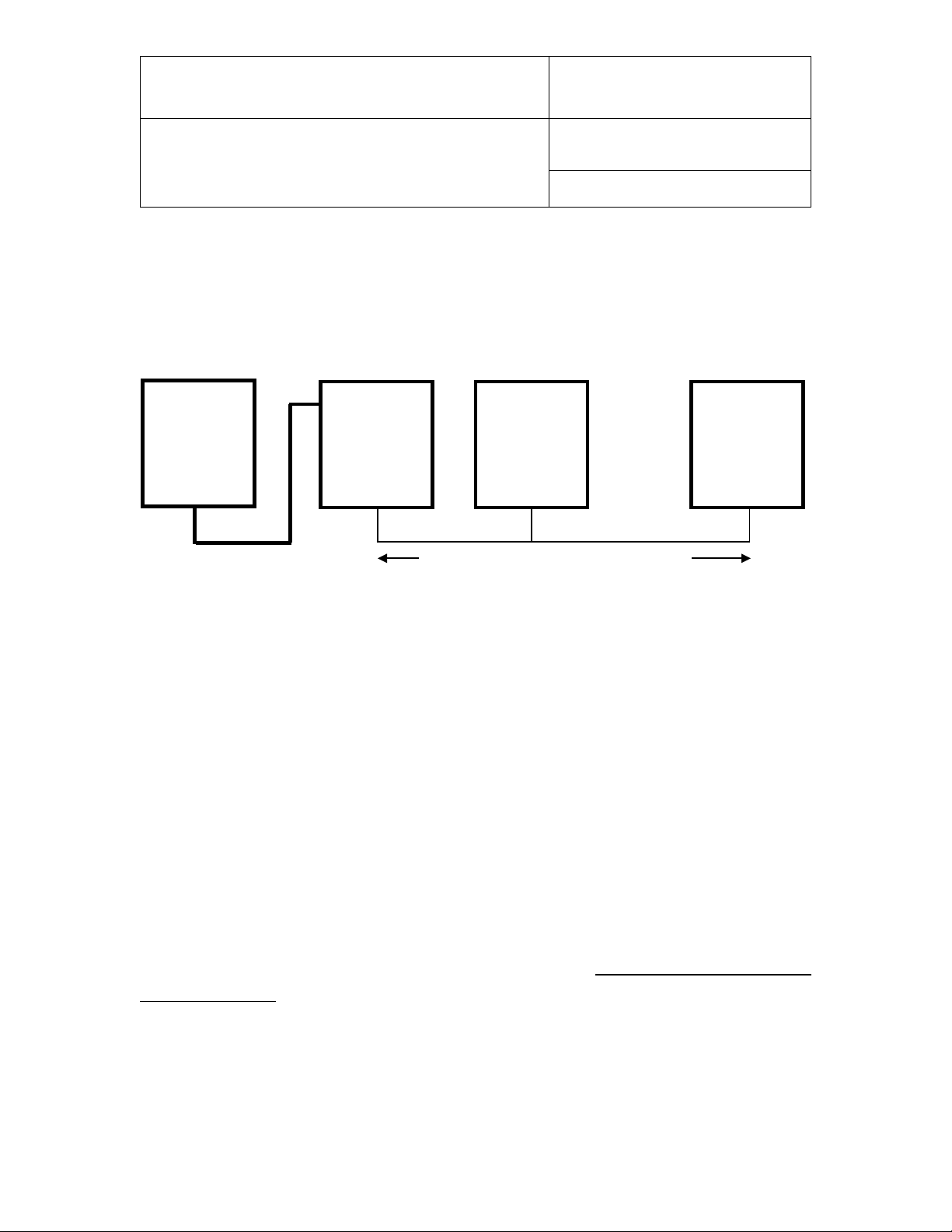
IN-E-HL-NT-V2_15
RS485: 2 wires
PC (HW4)
USB port
Master
Address 2
Address 64
NT
USB
RS485
RS485
RS485
Multi-drop: up to 1000m (3300 ft)
Slave
Slave
Document code Unit
Rotronic AG
Bassersdorf, Switzerland
HygroLog HL-NT data logger:
instruction manual
Document title
Instruction Manual
Document Type
Page
62 of 74
Example: HygroLog HL-NT and docking station with USB port
The number of HygroLog HL-NT and docking station with USB port that can be directly connected
to a PC depends on the number of USB ports available on the PC.
Address 1
IMPORTANT:
• If you change an instrum ent from master to s lave, be sure to change the RS address of the
instrument to 00 bef ore establishi ng the RS-4 85 connection . Not doing s o ma y prevent HW 4
from detecting the instrument. Af ter detecting th e instrum ent, HW4 will autom atically chang e
the RS address to 02 or higher . Pl ease n ote that HW4 m a y eventual ly chang e the ad dres s of
any master with address 00.
• All devices connec ted to t h e s am e RS-485 multi-drop s houl d us e the same Baud rate and the
same communications protocol.
• Docking stations with Ethernet (TCP/IP) interface: please note that the Baud rate of the
HygroLog HL-NT and the B aud r ate of the d oc king station internal Ethernet module should be
set to the same value
The RS485 wiring can be done with a twisted pair (2-wire, telephone type) and wall mounted RJ45
receptacles (see Electric al installation guide lines in thi s manual). Be sure to obse rve the polarit y
for each connection. Us ing 4-wire cable, of f ers the opti on of po weri ng a ll d evic es in the multi-drop
from a single DC voltage source.
© 2009-2015; Rotronic AG IN-E-HL-NT-V2_15

IN-E-HL-NT-V2_15
• Bus signals such as RS485
Document code Unit
Rotronic AG
Bassersdorf, Switzerland
HygroLog HL-NT data logger:
instruction manual
Document title
Instruction Manual
Document Type
Page
63 of 74
9.4 General wiring guidelines
Power supply wiring
Heavy machinery and instrumentation should not share the same power supply wiring. If this cannot
be avoided, noise filters and surge protectors should be used. Most UPS devices have those
features already integrated.
General guidelines for signal cables
The following guide lines are derived from European Standard EN 50170 for the transm ission of
signals by copper wires. When planning an installation, the rules provided by EN 50170 should be
followed under co nsideration of local circum stances to determine the pos ition of machines and
equipment.
All ROTRONIC products are tested for Electrom agnetic C ompatibilit y according t o EMC Direc tive
2004/106/EG and following European standards:
o EN 61000-6-1: 2001, EN 61000-6-2: 2005
o EN 61000-6-3: 2005, EN 61000-6-4: 2001 + A11
Whenever the level of electrom agnetic interference is expected to be high, both the instruments
and signal cables should be placed as far away as possible from the source of interference.
In general, signal cables should be installed in bundles or channels / conduits, separate from other
cables as indicated in the table below:
• Data signals for PCs, printers etc.
• shielded analog inputs
• unshielded direct current (<= 60V)
• shielded process signals (<= 25 V)
• unshielded alternate current (<= 25V)
• coaxial cables for CRT monitors
in common bundles or channels / conduits
© 2009-2015; Rotronic AG IN-E-HL-NT-V2_15

IN-E-HL-NT-V2_15
• direct and alternate current > 400 V
Document code Unit
Rotronic AG
Bassersdorf, Switzerland
HygroLog HL-NT data logger:
instruction manual
Document title
• direct current from 60 V to 400 V
(unshielded)
• alternate current from 25V to 400 V
(unshielded)
(unshielded)
• Telephone lines
• lines leading into EX-rated areas
in separated bundles or channels /
conduits, without minimum distance
in separated bundles or channels /
conduits, without minimum distance
Instruction Manual
Document Type
Page
64 of 74
Lightning protection
Cabling in areas with a r isk of lightning requires a l ightnin g pr o tec ti on. For c ab ling underground in
between buildings, we rec o m m end the use of special f i ber optic cables. If this is n ot p oss ibl e, us e
copper cables that are suitable for underground installation.
9.5 Guidelines for RS-485 wiring
See document E-DV04-RS485.01: RS485 Network Installation and Start-up Guidelines
© 2009-2015; Rotronic AG IN-E-HL-NT-V2_15

IN-E-HL-NT-V2_15
Document code Unit
Rotronic AG
Bassersdorf, Switzerland
HygroLog HL-NT data logger:
instruction manual
Document title
Instruction Manual
Document Type
Page
65 of 74
10. HygroClip probe adjustment procedures
10.1 Single Point adjustment
Important:
Probe adjustment can’t be done via WEB docking stations.
Definition
The Single-Point function permits to do a 1-point adjustment (temperature or humidity) of a
ROTRONIC HygroClip 2igital probe against a known reference environment. This function is limited
to a simple offset adjustment that is applied across the entire measuring range.
Warning: a 1-point adjus tment is no substitute for a full calibrat ion (2 or more points). Doing a
1-point adjustment can improve accuracy over a narrow range of conditions but may also be
detrimental to accuracy at other conditions.
Procedure
IMPORTANT:
Always adjust temperature first (if temperature needs to be adjusted)
Wait for the probe to be at equilibrium before using the ADJUST function.
Use the UP or DOWN key to highlight any menu item. Press on the ENTER key to select the menu
item. Only the value of the item is highlighted . Use the UP or DOW N key to review the availa ble
choices or to change a numerical value. W hen the desired se lection or valu e is displayed, pr ess
on the ENTER key. The entire line corres pon din g to th e menu item is highlight ed aga in. Make the
appropriate selections from the ADJUST menu:
• Probe: name of the probe to be adjusted (custom name specified by user)
• To change the probe, use t he up or down arrow k ey to highlight probe and press ENTER.
Use the arrow keys to change the probe and press ENTER to confirm the selection.
• Adjust: select here the parameter to be adjusted
• Humidity: humidity adjustment against a stable environment of known value.
© 2009-2015; Rotronic AG IN-E-HL-NT-V2_15

IN-E-HL-NT-V2_15
Document code Unit
Rotronic AG
Bassersdorf, Switzerland
HygroLog HL-NT data logger:
instruction manual
Document title
• Humi RHS: humidity adjustment against a ROTRONIC certified standard 1)
Temperature: temperature adjustment against a stable environment of known value.
1) For adjusting humidity, ROTRONIC offers convenient, certified humidity standards to
generate known humidity values (see separate probe calibration manual).
• Mode: select Single Point
• RefValue: Use the UP or D OWN k ey to change the num erical value of the r eference to b e
used for the adjustm ent. F or a faster change of the n umeric al value, k eep the k ey press ed
down. If using a ROT RONIC hum idity stan dard (H um i RHS), us e the m ean value (at 23°C)
written on the certificate supplied with the standard.
Note: in the RHS mode, the software automatically compensates for the effect of temperature
on the humidity standard. No additional correction is required.
• ADJUST: highlight this menu item and press on ENTER to do the adjustment
• EXIT: highlight this menu item and press on ENTER to exit the ADJUST function
Instruction Manual
Document Type
Page
66 of 74
The bottom of the display shows the word “Current” and the value read by the probe at the time the
ENTER key was pressed
Note: you can exit the ADJ UST func tion at an y time ( without adjus ting the pr obe ) by pres sin g the
MENU key.
© 2009-2015; Rotronic AG IN-E-HL-NT-V2_15

IN-E-HL-NT-V2_15
Document code Unit
Rotronic AG
Bassersdorf, Switzerland
HygroLog HL-NT data logger:
instruction manual
Document title
Instruction Manual
Document Type
Page
67 of 74
10.2 Multi-Point adjustment
This is an HW 4 sof tware f unc tion and is avail ab le on ly when the HygroLog HL-NT is connected to
a PC running the HW4 software (version 2.3.0 or higher).
See the following documents:
o E-M-HW4v3-F2-013: HW4 software version 2: Device Manager – HygroLog HL-NT data logger
o E-M-HW4v3-A2-001: HW4 software version 2: Probe Adjustment function AirChip 3000
devices
11. Warnings and useful tips
• Battery Power: when no external AC adapter is connected, us e the HW 4 softwar e to set the
display to automatic all y go bla nk after a specific time inter v al w hen ther e is no k eypa d ac ti v ity
or communication over the UART interface.
Set both the display refresh rate and the log interval to the highest values compatible with your
application.
Avoid using a docking station with internal electronics without using an AC adapter.
Do not connect several probes to the HygroLog HL-NT without using an AC adapter.
• Do not attempt to charge a regular battery: when using a regular battery, configure the
logger with HW4 so as to disable the internal batter y charge function of the logger. Tr ying to
recharge a regular battery is potentially dangerous.
• Date and Time Format: prior to using your logger for the first time, be sure to verify the
following configuration settings: date format (including separator), time format (including
separator) and decimal sep arator. In or der t o be able to r ead log f iles on a PC, th ese s ettings
must be identical to the se ttings of the PC operating system. If necess ary, use HW4 to reconfigure your logger.
• Internal Probe (Input 1): for a faster response, use the probe in the extended position.
Compliance with ERES regulatory requirements: Use the HW4 software to disable either
the MENU key or t he entire keypad. Dis ab lin g t he M E NU key prevents una uthor i zed c ha nges
to the configuration of the HygroLog HL-NT and also prevents any probe adjust ment.
© 2009-2015; Rotronic AG IN-E-HL-NT-V2_15

IN-E-HL-NT-V2_15
Document code Unit
Rotronic AG
Bassersdorf, Switzerland
HygroLog HL-NT data logger:
instruction manual
Document title
Instruction Manual
Document Type
Page
68 of 74
12. Communications protocol
The communications prot ocol used b y the HygroLog HL-NT is the sam e as for previous ver sions
of the HygroLog NT. For customers who for any reason cannot use the HW4 software, a description
of the HygroLog HL-NT communications pr otoco l is a va ilabl e i n document Com_NT.pdf available
directly from ROTRONIC or from our web site.
13. Firmware updates
Firmware updates require a return to the factory and cannot be done with the HW4.
© 2009-2015; Rotronic AG IN-E-HL-NT-V2_15

IN-E-HL-NT-V2_15
Model
HygroLog HL-NT2
HygroLog HL-NT3
Internal Humidity /
Plug-in ROTRONIC HC2-S
Operating limits
Humidity
0…100 %RH
Temperature
-30…70 °C (-22…158°F) / -10…60 °C (14…140°F) with display
Operating limits battery
Alkaline battery
-10…+50 °C (14…122°F)
Lithium battery
-30…+70 °C (-22….158°F)
Measuring range
Internal probe
0…100 %RH, same temperature limits as logger
External probes
See probe specifications
Accuracy at 23°C
See probe specifications
Interface
Logger
UART
Docking station
RS-232 or USB or Ethernet (wired or wireless) / RS-485
Serial interface
Baud rate : 19200 or 57600
Internal Power supply
9V battery ≥500 mAh
External power supply
Via docking station (allows use of a rechargeable battery)
Battery lifetime
> 1 year - w/o display, 1 probe, 15 min. log interval
Optional Display
Graphic LC display with backlight
Document code Unit
Rotronic AG
Bassersdorf, Switzerland
HygroLog HL-NT data logger:
instruction manual
Document title
14. Specifications
Temperature probe
electronics
Instruction Manual
Document Type
Page
69 of 74
(RS-232 / RS-485)
© 2009-2015; Rotronic AG IN-E-HL-NT-V2_15
HygroClip 2 probes are available for temperatures
within the range of -100…200°C / -148…392°F
Data bits : 8
Stop bits : 1
Parity : none

IN-E-HL-NT-V2_15
Model
HygroLog HL-NT2
HygroLog HL-NT3
Event logging
Practically unlimited number of events such as configuration
Internal Menu
Simplified functions, viewing of logged data
Internal probe adjustment
N/A
Direct from internal menu
External probe adjustment
Direct from internal menu (HygroClip probes only)
Probe inputs- Logger
One HygroClip 2 probe
Up to 3 HygroClip 2 probes
Probe inputs - Docking
Up to 4 probes (HygroClip 2 probes, analog probes or RTD
Plug-in Memory Card
Compact flash memory card (64 MB standard - up to 1 GB)
Internal memory
EEPROM
Memory capacity
400,000 data points in text file format
Log interval
Programmable from 5 sec to 24 hours
Log mode
Start / Stop, with programmable date and time
Alarm function
Optical and acoustical - programmable
Housing
ABS, protection grade IP65
Conformance
FDA CFR 21 / 11 / GAMP4
Anti-theft protection
Use docking station
Logger dimensions
Logger
155 x 106 x 37 mm
Docking station
110 x 70 x 37 mm
Weight
Logger
about 300 g
Docking station
about 175 g
NT desk stand
About 350 g
Document code Unit
Rotronic AG
Bassersdorf, Switzerland
HygroLog HL-NT data logger:
instruction manual
Document title
changes, alarm, etc.
station
probes (Pt100) and 2 digital signals (depends on model)
Instruction Manual
Document Type
Page
70 of 74
(64 MB compact card)
752,000 data points in encoded binary format (protected)
© 2009-2015; Rotronic AG IN-E-HL-NT-V2_15

IN-E-HL-NT-V2_15
Document code Unit
Rotronic AG
Bassersdorf, Switzerland
HygroLog HL-NT data logger:
instruction manual
Document title
Instruction Manual
Document Type
Page
71 of 74
Docking Station
Dimensions in mm
© 2009-2015; Rotronic AG IN-E-HL-NT-V2_15

IN-E-HL-NT-V2_15
Order Code
Description
NT-Desk
Desktop stand for HygroLog HL-NT with docking station
AC1211
AC adapter 12VDC / 200mA, includes adapter for US receptacles
11.01.6218
Data cable RS232 - docking station to PC (length 1.8 m / 5.9 ft)
2/11/8818
Data cable USB type A-B - docking station to PC (length 1.8 m / 5.9 ft)
AC1614-02
RS-485 cable with 3-pin connector and tinned ends. Suitable for
AC-NT64MB
Compact flash memory card 64 MB
15.08.6212
Flash card reader, incl. USB cable and driver
Document code Unit
Rotronic AG
Bassersdorf, Switzerland
HygroLog HL-NT data logger:
instruction manual
Document title
15. Accessories
connecting to a terminal box. Length 2 meter / 6.5 ft.
Instruction Manual
Document Type
Page
72 of 74
For accessories and parts such as the HW4 software, probe extension cables, calibration
accessories and spare dust filters, please see document E-M-HC2-accessories
© 2009-2015; Rotronic AG IN-E-HL-NT-V2_15

IN-E-HL-NT-V2_15
Document File Name
Contents
E-M-HC2-accessories
Accessories and parts for probes, indicators and transmitters
E-T-AC3000-DF-V1
E-M-HW4v3-DIR
List of the HW4 manuals
HW4 software version 3: General instructions and functions common
HW4 software version 3: Device Manager – HygroLog HL-NT data
E-M-HW4v3-F2-001
HW4 software version 3: Probe Adjustment function AirChip 3000
HW4 software version 3: Data Recording Function AirChip 3000
Configuration procedures for ROTRONIC devices
Temperature and humidity calibration basics
Document code Unit
Rotronic AG
Bassersdorf, Switzerland
HygroLog HL-NT data logger:
instruction manual
Document title
16. Supporting documents
E-M-HC2 Probes-V1
E-M-HW4v3-Main
E-M-HW4v3-F2-013
HygroClip 2 (HC2) Humidity Temperature Probes, User Guide
AirChip 3000 Description and Main Functions
to all devices
logger
Instruction Manual
Document Type
Page
73 of 74
E-M-HW4v3-A2-001
E-M-HW4v3-DR-001
E-M-AC3000-CP
E-DV04-RS485.01
E-M-TCPIP-Conf
E-M-CalBasics
E-T-HumiDefs
HW4 software version 3: Device Manager – HC2 probe series
devices
Devices
AirChip 3000 Communication Protocol Options
RS485 Network Installation and Start-up Guidelines
with Ethernet (TCP/IP) interface
Instructions for using the ROTRONIC humidity standards
Humidity Definitions
Note: All document file names have an extension corresponding to the document release number.
This extension is not shown in the above table.
© 2009-2015; Rotronic AG IN-E-HL-NT-V2_15
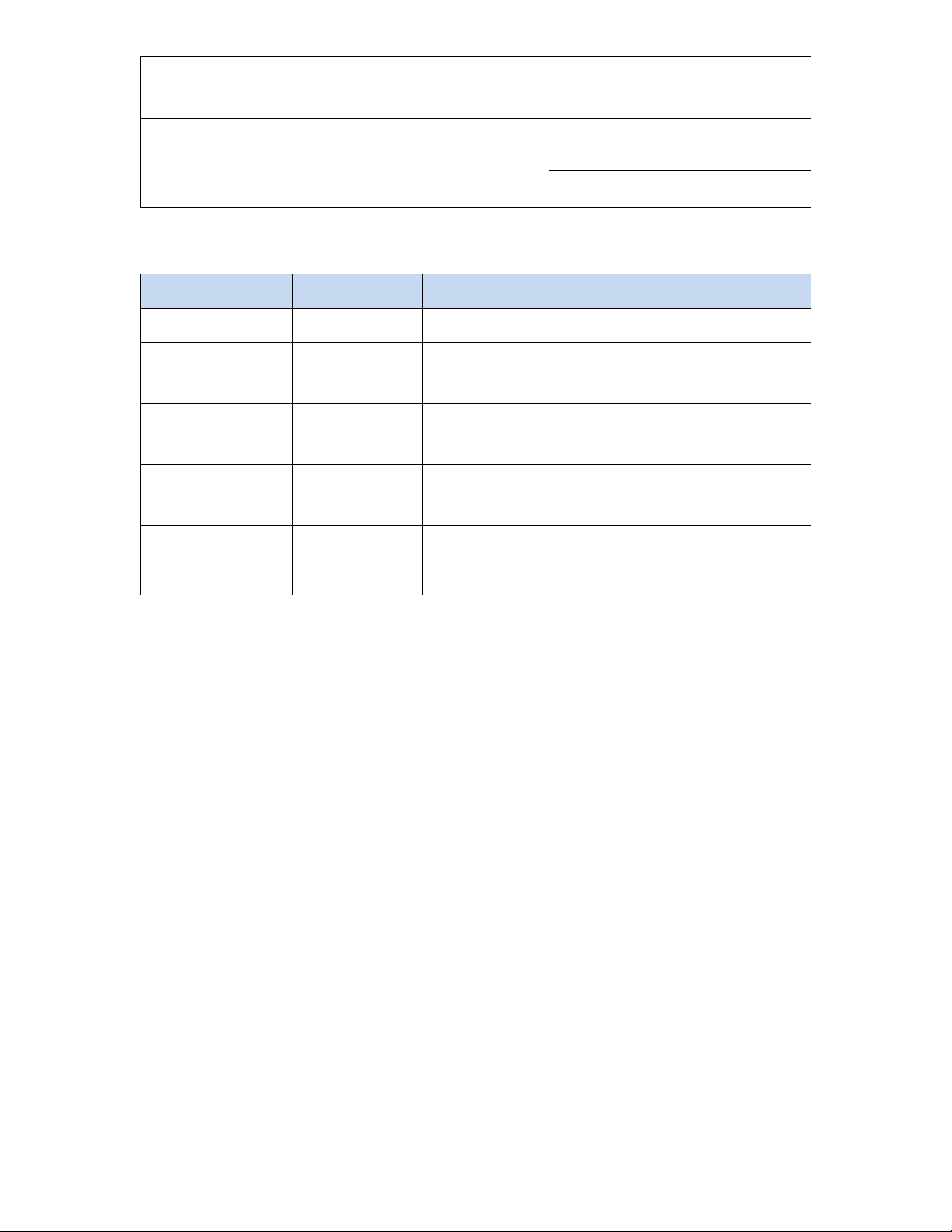
IN-E-HL-NT-V2_15
Doc. Release
Date
Notes
_10
Aug. 20, 2009
Original release
Added Wireless LAN specifications
Changed the pin-out specification for the 1-channel
Additional informat ion:
_14
Dez. 03, 2014
Connector type of RTD temperature probes added
_15
March 16,2015
Chapter 3.2.1 updated with better description
Document code Unit
Rotronic AG
Bassersdorf, Switzerland
HygroLog HL-NT data logger:
instruction manual
Document title
17. Document releases
_11 Aug. 26, 2010
_12 Jan. 4, 2012
_13 Nov. 25, 2014
Instruction Manual
Document Type
Page
Updated document to HW4 software v.3
analog probe
no probe adjustment via WEB docking station
74 of 74
© 2009-2015; Rotronic AG IN-E-HL-NT-V2_15
 Loading...