

Page 1

DOCKINGSTATION HL-NT
KURZBEDIENUNGSANLEITUNG /
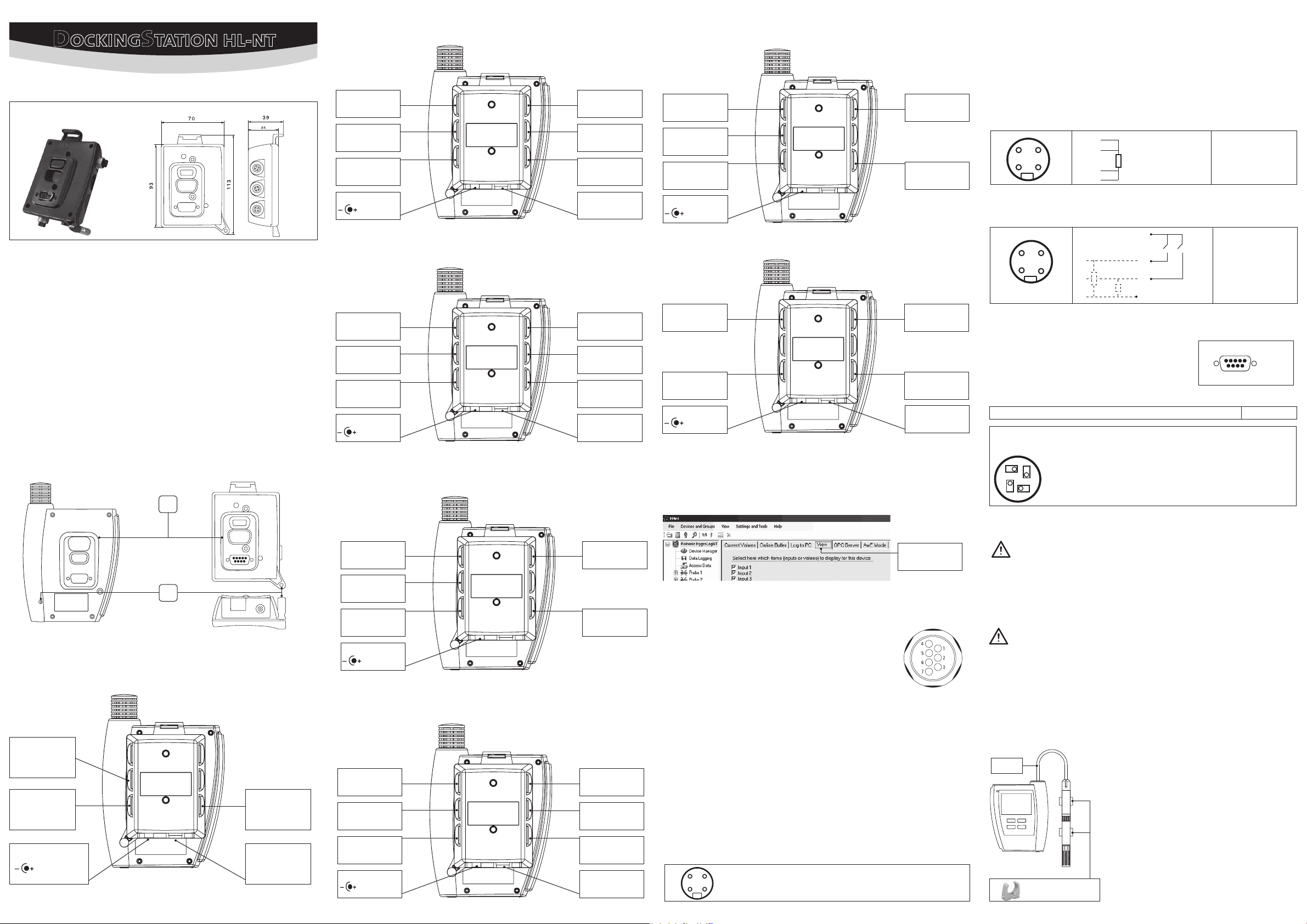
Abmessungen /
Diese Kurzbedienungsanleitung beschränkt sich auf die Beschreibung der wichtigsten Funktionen
und der Installation des Gerätes. Die detaillierte Bedienungsanleitung nden Sie im Internet
unter: www.rotronic.com
These short instructions are limited to a description of the main functions and installation of the
device. The detailed instruction manual can be found on the internet at: www.rotronic.com
Mechanische Installation Dockingstation /
Verwenden Sie die 2 mitgelieferten Schrauben, um die Dockingstation an einer Wand zu befestigen.
Die Bestückung der Steckverbindungen variiert je nach Modell.
Use the two screws to x the docking station onto a wall. Connector conguration depends on
the model.
Montage vom Hygrolog NT /
Platzieren Sie den Hygrolog NT über der Dockingstation, dass der Bereich [A] genau übereinander
passt. Drücken Sie den Hygrolog NT auf die Dockingstation und xieren diesen mit der Schraube [B].
Diese kann zusätzlich mit einem Schloss gesichert werden.
Place the HygroLog NT on the docking station so as to match the two areas [A]. Press lightly one
against the other and secure the assembly with threaded pin [B]. When the docking station is
mounted on a wall, a small padlock (not shown) may be put through pin [B] to prevent removal of
the HygroLog NT from the docking station.
Dimensions
Installation HygroLog NT
SHORT INSTRUCTION MANUAL
Mechanical installation docking station
[A]
Fühlerzuordnung /
Probe assignment
HL-DS-U1 / HL-DS-U2 / HL-DS-U2-420
Fühlereingang 6
Probe input 6
Fühlereingang 7
Probe input 7
RS-485
12VDC Power
(AC1211)
Fühlerzuordnung /
Probe assignment
HL-DS-U4 / HL-DS-U4-420
Fühlereingang 6
Probe input 6
Ethernet RJ-45
RS-485
12VDC Power
(AC1211)
Fühlerzuordnung /
Probe assignment
HL-DS-U4-WL / HL-DS-U4-WEB / HL-DS-U4-WEB-WL
Fühlereingang 4
Probe input 4
Fühlereingang 5
Probe input 5
Digitale Eingänge
Logical inputs
RS-232: -U1
USB: -U2/-U2-420
Fühlereingang 4
Probe input 4
Fühlereingang 5
Probe input 5
Digitale Eingänge
Logical inputs
Fühlereingang 7
Probe input 7
Fühlerzuordnung /
Probe assignment
HL-DS-PT4 / HL-DS-PT4-WL
Eingang 6: Pt100
Input 6: Rtd
PT4: Ethernet RJ45
PT4-WL: W-LAN
RS-485
12VDC Power
(AC1211)
Fühlerzuordnung /
Probe assignment
Eingang 4: Pt100
Input 4: Rtd
Digitale Eingänge
Logical inputs
HL-DS-R1
Relais 2
Relay 2
RS-485
12VDC Power
(AC1211)
Relais 1
Relay 1
Digitale Eingänge
Logical inputs
USB
Software Einstellung / Software Settings (HW4)
Damit die entsprechenden Ein-/Ausgänge konguriert und angezeigt werden können, stellen Sie
sicher, dass diese in der HW4 eingeschaltet sind.
For conguration and display of corresponding in- and outputs, make sure that these have been
selected in the View window of HW4.
Hinweis: Verwenden Sie die Anschlüsse 3 und 4 zur Spannungsversorgung von vernetzten Geräten
mit einer einzigen externen 12 VDC Spannungsquelle mit adäquater Leistung. Stift 4 ist nicht mit
der 12 VDC Versorgungsspannung der Docking Station verbunden.
Note: use pins 3 and 4 to power multi-dropped instruments with a single external 12 VDC power
supply with adequate mA rating. Pin 4 and the 12 VDC power jack of the docking station are not
connected.
Pt-100 Eingänge / Pt-100 Inputs 4, 5, 6, 7: (HL-DS-PT-2, HL-DS-PT-4)
(Lötseite des Steckers /
2
1
Digitale Eingänge /
Lötseite des Steckers
solder side of matching male connector)
3
4
1
2:
3:
4-Draht Pt100
4-wire RTD
4:
Digital Inputs
(solder side of matching male connector)
1: DC (+)
2: Measurement (+)
3: Measurement (-)
4: DC (-)
1
2
1
3
2
4
3
1: + 3.5 VDC
2: Eingang / Input 1
3: Eingang / Input 2
4: GND
4
Hinweis: Interne Pull-Down Widerstände setzen die Eingänge bei offenem Kontakt auf 0.
Note: an internal pull-down resistor sets each input to 0 when the contact is open.
RS232 Schnittstelle (Lötseite des Steckers)
RS-232 port (solder side of matching male connector)
Relais (Bei Ohmscher Last) /
Maximale Schaltspannung /
Anschussseite der Buchse /
4
3
1
2
Relay (Resistive load)
Maximum switching voltage
Connecting side of matching female connector
1: N.C. Öffnerkontakt (Relais stromlos) /
2: Gemeinsamer Kontakt /
Common
3: N.O. Schliesserkontakt (Relais bestromt) /
4: Nicht gebraucht /
Not used
165
2: Tx
3: Rx
5: GND
9
2A / 250 VAC
contact (Relay de-energized)
contact (Relay energized)
HygroLog HL-NTxx mit Ethernet Dockingstationen
HygroLog HL-NTxx with Ethernet Docking Stations
[B]
Fühlerzuordnung /
HL-DS-NT0 / HL-DS-NT1 / HL-DS-NT2 / HL-DS-NT3 / HL-DS-NT4 (WL/WEB)
NT-4, NT-4-WEB
Ethernet RJ-45
NT-4-WL: W-LAN
NT2/3/4/4-WL
RS-485
NT1/NT2/NT3/NT4
12VDC Power
(AC1211)
Probe assignment
NT-4, NT4-WL
Digitale Eingänge
Logical inputs
NT2: RS-232
NT3: USB
Fühlereingang 6
Probe input 6
U4-WL/U4-WEB-WL:
W-LAN
U4-WEB: Ethernet
HL-DS-U4-WL: RS-485
HL-DS-U4-WEB-(WL): —
12VDC Power
(AC1211)
Fühlerzuordnung /
HL-DS-PT2
Eingang 6: Pt100
Input 6: Rtd
Eingang 7: Pt100
Input 7: Rtd
RS-485
12VDC Power
(AC1211)
Probe assignment
Fühlereingang 4
Probe input 4
Digitale Eingänge
Logical inputs
Eingang 4: Pt100
Input 4: Rtd
Eingang 5: Pt100
Input 5: Rtd
Digitale Eingänge
Logical inputs
USB
Ansicht/
View
Digitale / analoge Fühlereingänge /
Digital or analogue Probe inputs
Digitale Fühlersignale (HC2-x Serie) oder analoge Signale von Fremdfühlern können verarbeitet werden. Die Fühlertypen Digital (Standard) oder
Analog werden mit der Software HW4 eingestellt. Analoge Fühler können
mit dem optional erhältlichen Kabel A-02xx angeschlossen werden. Der
Verdrahtungsplan liegt dem Kabel bei.
Digital probe signals (HC2-x series) or analogue signals of third party
probes may be processed. The probe type digital (standard) or analogue
may be selected using the HW4 software.
Analogue probes may be connected to the docking station using a cable A02xx (optionally available). The wiring diagram is provided with the cable.
Spannungseingang /
Gilt für /
applies to
voltage input:
0...3.3 VDC
: HL-DS-U1; HL-DS-U2; HL-DS-U4; HL-U4-WEB
HC2-Stecker
Connector HC2
HL-U4-WEB-WL; HL-U4-WL
Stromeingang /
current input :
4...20 mA.
Eingang welcher über einem internen 150 Ohm Widerstand
in eine Spannung von nominal 600..3000mV
(nominal) gewandelt wird.
The input uses an internal 150 Ohm resistor to convert
4…20 mA to 600…3000 mV (nominal).
Gilt für /
applies to:
RS-485 (Lötseite des Steckers /
2
1
HL-DS-U2-420, HL-DS-U4-420, HL-DS-U4-420-WEB
solder side male connector)
3
4
1: 485 (-)
2: 485 (+)
3: GND (optional)
4: DC +
(siehe Hinweis /
see note
)
Wichtiger Hinweis
Die Docking Stationen mit Ethernet Netzwerkanschluss erwärmen sich im Dauerbetrieb um bis zu
6…8 °C. Dies ist durch den relativ hohen Stromverbrauch bedingt. Diese Wärme überträgt sich auf
den angedockten Logger. Die Datenlogger sollten daher nicht mit dem internen Fühler 1 betrieben
werden. Für genaue Messungen verwenden Sie das Verlängerungskabel E2-FA (optional erhältlich),
um den Fühler von der warmen Dockingstation abgesetzt zu betreiben. Platzieren Sie den Fühler
soweit wie möglich vom Logger entfernt, und achten Sie darauf, dass der Fühler nicht über dem
Logger installiert ist. Installieren Sie das Kabel gemäss untenstehender Zeichnung.
Important notice
The docking stations with Ethernet connection have self heating issues due to their relatively high
current consumption. The temperature difference may be as big as 6…8 °C. Warmth is transferred
also to the logger attached to the docking station. Therefore, the loggers should not be operated
with the internal probe 1. For accurate measurements, use extension cable E2-FA (optionally available), to separate the probe from the logger and the heating docking station. Place the probe as far
away as possible from and not above the logger. Install the cable according to the sketch below.
ROTRONIC AG, CH-8303 Bassersdorf
E2-FA3 A
AC1319
Tel. +41 44 838 11 44, www.rotronic.com
ROTRONIC Messgeräte GmbH, D-76275 Ettlingen
Tel. +49 7243 383 250, www.rotronic.de
ROTRONIC SARL, 56, F - 77183 Croissy Beaubourg
Tél. +33 1 60 95 07 10, www.rotronic.fr
ROTRONIC Italia srl, I- 20157 Milano
Tel. +39 2 39 00 71 90, www.rotronic.it
ROTRONIC Instruments (UK) Ltd, West Sussex RH10 9EE
Phone +44 1293 571000, www.rotronic.co.uk
ROTRONIC Instrument Corp, NY 11788, USA
Phone +1 631 427-3898, www.rotronic-usa.com
ROTRONIC South East Asia Pte Ltd, Singapore 339156
Phone +65 6294 6065, www.rotronic.com.sg
ROTRONIC Shanghai Rep. Office, Shanghai 200233, China
Phone +86 40 08162018, www.rotronic.cn
12.0 79 8.2 00 4
Page 2
DOCKINGSTATION HL-NT
MODE D'EMPLOI ABRÉGÉ /
Dimensions /
Dimensioni
MANUALE D'ISTRUZIONI BREVE
Affectation des capteurs /
Assegnazione delle sonde
HL-DS-U1 / HL-DS-U4 / HL-DS-U4-420
Entrée de capteur 6
Entrata sonda 6
Entrée de capteur 7
Entrata sonda 7
RS-485
Entrée de capteur 4
Entrata sonda 4
Entrée de capteur 5
Entrata sonda 5
Entrées numériques
Entrate digitali
Affectation des capteurs /
HL-DS-PT4 / HL-DS-PT4-WL
Entrée 6: Pt100
Entrata 6: Pt100
PT4: Ethernet RJ45
PT4-WL: W-LAN
RS-485
Assegnazione delle sonde
Entrée 4: Pt100
Entrata 4: Pt100
Entrées numériques
Entrate digitali
Remarque: utilisez les broches 3 et 4 pour l’alimentation électrique des appareils en réseau avec
une seule source externe d’alimentation 12 VCC de puissance adéquate. La broche 4 n’est pas
reliée à la tension d’alimentation de 12 VCC de la station d’accueil.
Nota: utilizzare i collegamento 3 e 4 per l’alimentazione di tensione di apparecchi collegati in rete
con una sola fonte esterna di tensione a 12 VDC di rendimento adeguato. Il pin 4 non è collegato
alla tensione di alimentazione a 12 VDC della stazione Docking.
Entrées Pt-100 / Entrate Pt-100 4, 5, 6, 7: (HL-DS-PT-2, HL-DS-PT-4)
(Vue du connecteur côté soudures /
2
1
3
4
lato di saldatura del connettore di presa)
1
2:
3:
4-Draht Pt100
Pt100 a 4 li
4:
1: DC (+)
2: Measurement (+)
3: Measurement (-)
4: DC (-)
Ce mode d’emploi abrégé se limite à la description des fonctions essentielles de cet appareil.
Vous trouverez un mode d’emploi détaillée sur notre site Internet:
www.rotronic.com
La presente guida rapida si limita a descrivere le funzioni principali dello strumento e la sua
installazione. Le istruzioni d’uso dettagliate sono disponibili in Internet all’indirizzo:
www.rotronic.com
Installation mécanique de la station /
Installazione meccanica della Dockingstation
Utilisez les 2 vis fournies avec l’appareil pour xer la station d’accueil à une paroi. La conguration
des connecteurs de raccordement varie selon les modèles.
Utilizzare le due viti facenti parte della fornitura per ssare la stazione Docking ad una parete.
La congurazione dei connettori varia in base al modello.
Montage de l’HygroLog NT /
Montaggio di Hygrolog NT
Positionnez l’HygroLog NT au-dessus de la station d’accueil, de façon à faire coïncider exactement
les parties [A]. Poussez légèrement l’Hygrolog contre la station d’accueil et xez-le avec la vis [B].
L’appareil peut également être verrouillé par un cadenas.
Posizionare l’Hygrolog NT sulla stazione Docking, in modo che le due aree [A] coincidano perfetta-
mente. Premere l’Hygrolog NT sulla stazione Docking e ssarlo con la vite [B].
È inoltre possibile utilizzare un lucchetto di sicurezza.
[A]
[B]
Affectation des capteurs /
HL-DS-NT0 / HL-DS-NT1 / HL-DS-NT2 / HL-DS-NT3 / HL-DS-NT4 (WL/WEB)
Assegnazione delle sonde
12VDC Power
(AC1211)
Affectation des capteurs /
Assegnazione delle sonde
HL-DS-U4 / HL-DS-U4-420
Entrée de capteur 6
Entrata sonda 6
Ethernet RJ-45
RS-485
12VDC Power
(AC1211)
Affectation des capteurs /
Assegnazione delle sonde
HL-DS-U4-WL / HL-DS-U4-WEB / HL-DS-U4-WEB-WL
Entrée de capteur 6
Entrata sonda 6
U4-WL/U4-WEB-WL:
W-LAN
U4-WEB: Ethernet
HL-DS-U4-WL: RS-485
HL-DS-U4-WEB-(WL): —
12VDC Power
(AC1211)
Affectation des capteurs /
Assegnazione delle sonde
HL-DS-PT2
RS-232: -U1
USB: -U2/-U2-420
Entrée de capteur 4
Entrata sonda 4
Entrée de capteur 5
Entrata sonda 5
Entrées numériques
Entrate digitali
Entrée de capteur 7
Entrata sonda 7
Entrée de capteur 4
Entrata sonda 4
Entrées numériques
Entrate digitali
12VDC Power
(AC1211)
Affectation des capteurs /
Assegnazione delle sonde
HL-DS-R1
Relais 2
Relè 2
RS-485
12VDC Power
(AC1211)
Réglage logiciel /
Impostazioni software
(HW4)
Relais 1
Relè1
Entrées numériques
Entrate digitali
USB
An de pouvoir congurer et ajuster les entrées/sorties correspondantes, assurez-vous que
celles-ci sont activées dans le logiciel HW4.
Per congurare e visualizzare le corrispondenti entrate/uscite, assicuratevi che siano inserite
nell’HW4
Vue/Visione
Entrées numériques/analogiques pour capteurs
Segnali di entrata digitali / analogici per sonde
Les signaux numériques de capteurs (série HC2-x) ou analogiques de
capteurs étrangers peuvent être exploités. Le type de capteur, numérique
(standard) ou analogique est paramétré avec le logiciel HW4. Les capteurs
analogiques peuvent être raccordés avec le câble A-02xx disponible en
option. Le schéma des connexions est fourni avec le câble.
I segnali digitali delle sonde ( serie HC2-x) o i segnali analogici di sonde
di terzi possono essere elaborati. Le sonde di tipo digitale ( standard) o
analogiche vengono impostate con il software HW4.Le sonde analogiche
possono essere allacciate con il cavo opzionale A-02xx . La descrizione
Conntecteur HC2
Connettore HC2
dei collegamenti è allegata al cavo.
Entrées numériques /
(Vue du connecteur côté soudures /
Entrate digitali
lato di saldatura del connettore di presa)
1
2
1
3
2
4
3
1: + 3.5 VDC
2: Entrée / Entrata 1
3: Entrée / Entrata 2
4: GND
4
Remarque: des résistances internes de décharge mettent les entrées à 0 quand le contact est ouvert.
Nota: le resistenze interne pull-down impostano le entrate a 0 con contatto aperto.
Interface RS-232 (Vue du connecteur côté soudures)
RS-232 port (lato di saldatura del connettore di presa)
Relais (Avec charge ohmique) /
Tension maximale de commutation /
Relè (Con carico ohmico)
Tensione massima di commutazione
165
2: Tx
3: Rx
5: GND
9
2A / 250 VAC
Connexion côté de connecteur femelle correspondant
Lato di collegamento del connettore femmina
4
1
2
1: N.C.Ouverture (relais sans courant) /
2: Contact commun /
3
3: N.O. Fermeture (relais avec courant) /
4: Non utilisé /
Contatto comune
Non utilizzato
contatto in apertura (relè senza corrente)
contatto in chiusura (relè sotto corrente)
HygroLog HL-NTxx avec station d’accueil Ethernet
Hygrolog HL-NTxx con stazioni Docking Ethernet
Remarque importante
La consommation électrique relativement importante des stations d’accueil équipées de connexion
Ethernet augmente leur température de jusqu’à 6…8 °C. Cette chaleur est diffusée au logger
raccordé à la station. C’est pourquoi l’utilisation du capteur interne 1 devrait être évitée. Utilisez
le câble de rallonge optionnel E2-FA pour des mesures précises, an d’éloigner le capteur de la
station d’accueil. Placez le capteur aussi loin que possible du logger et veillez à ce qu’il ne soit pas
au-dessus de celui-ci. Installez le câble selon les indications du schéma ci-dessous.
Segnalazione importante
Le stazioni Docking con collegamento alla rete Ethernet si riscaldano, se utilizzate in esercizio continuo,
aumentando la temperatura di 6…8 °C. Tale fenomeno è dovuto al consumo relativamente elevato di
corrente. Tale calore si trasmette anche al logger collegato alla stazione. Pertanto i datalogger non dovrebbero essere fatti funzionare con la sonda interna 1. Per misurazioni precise, si consiglia di utilizzare
la prolunga E2-FA (disponibile come optional), per utilizzare la sonda separatamente dalla stazione
docking calda. Posizionare la sonda il più lontano possibile dal datalogger e controllare che a sonda
non sia installata sopra il datalogger. Installare il cavo seguendo le indicazioni del disegno a seguire.
NT-4, NT-4-WEB
Ethernet RJ-45
NT-4-WL: W-LAN
NT2/3/4/4-WL
RS-485
NT1/NT2/NT3/NT4
12 VDC Power
(AC1211)
NT-4, NT4-WL
Entrées numériques
Entrate digitali
NT2: RS-232
NT3: USB
Entrée 6: Pt100
Entrata 6: Pt100
Entrée 7: Pt100
Entrata 7: Pt100
RS-485
12VDC Power
(AC1211)
Entrée 4: Pt100
Entrata 4: Pt100
Entrée 5: Pt100
Entrata 5: Pt100
Entrées numériques
Entrate digitali
USB
Tension d’entrée:/
Valable pour/
Valida per:
Tensione di alimentazione:
HL-DS-U1; HL-DS-U2; HL-DS-U4;
0...3.3 VDC
HL-U4-WEB; HL-U4-WEB-WL; HL-U4-WL
Entrée en courant/
Assorbimento corrente:
4...20 mA.
Entrée convertie par une résistance interne de 150 Ohm en une tension nominale de 600...3000mV.
Entrata convertita in una tensione nominale di 600…3000mV , attraverso una resistenza interna
di 150 Ohm.
Valable pour /
RS-485 (Vue du connecteur côté soudures /
2
1
Valida per:
3
4
HL-DS-U2-420, HL-DS-U4-420, HL-DS-U4-420-WEB
lato di saldatura del connettore di presa)
1: 485 (-)
2: 485 (+)
4: DC +
(voir remarque /
V. nota
)
3: GND (optional)
E2-FA3 A
AC1319
ROTRONIC AG, CH-8303 Bassersdorf
Tel. +41 44 838 11 44, www.rotronic.com
ROTRONIC Messgeräte GmbH, D-76275 Ettlingen
Tel. +49 7243 383 250, www.rotronic.de
ROTRONIC SARL, 56, F - 77183 Croissy Beaubourg
Tél. +33 1 60 95 07 10, www.rotronic.fr
ROTRONIC Italia srl, I- 20157 Milano
Tel. +39 2 39 00 71 90, www.rotronic.it
ROTRONIC Instruments (UK) Ltd, West Sussex RH10 9EE
Phone +44 1293 571000, www.rotronic.co.uk
ROTRONIC Instrument Corp, NY 11788, USA
Phone +1 631 427-3898, www.rotronic-usa.com
ROTRONIC South East Asia Pte Ltd, Singapore 339156
Phone +65 6294 6065, www.rotronic.com.sg
ROTRONIC Shanghai Rep. Office, Shanghai 200233, China
Phone +86 40 08162018, www.rotronic.cn
12.0 79 8.2 00 4
 Loading...