

Page 1
SHORT INSTRUCTION MANUAL
Digital transmitter for humidity & temperature
Congratulations on your purchase of the new state-of-the-art HygroFlex8-series transmitter. Please
read these short instructions carefully before installing the device.
General description
The HygroFlex8-series devices are universal transmitters for transmission of humidity and temperature measurements. Compatible with all interchangeable HC2 probes. These short instructions are
limited to a description of the main functions and installation of the device. The detailed instruction
manual can be found on the internet at: www.rotronic.com
Dimensions / Connections
Wall version
192
102
85
192
31
Service interface
52
39.5
22.3
16
Digital connection
Measured Parameters
HygroClip2 probe:
Humidity and temperature. The HC2 probes measure relative humidity with a ROTRONIC Hygromer®
IN1 capacitive sensor and temperature with a Pt100 RTD.
Analog probe (general):
Any parameter measured by the probe. The parameter unit must be specied with the HW4 software
(Device Manager). Analog pressure probe: the unit used for barometric pressure is set with the
HW4 software > Device Manager > Unit System.
Probe inputs
The HF8 has two probe inputs. Using the HW4 software (Device Manager), each probe input can
be congured to accept one of the following:
HygroClip2 humidity-temperature digital probe:
Both inputs can be congured to read and display digital signal of a HygroClip2 probe.
1-channel analog probe (general):
To be compatible with the HF8 the analog probe must meet the following requirements: supply
voltage: max. 5 VDC, current consumption: max. 10 mA, output signal: 0 to max. 3.3 VDC. The HF8
uses a 12-bit A/D converter to digitize the probe analog signal and can be congured to measure
practically any parameter.
Analog pressure probe:
This is a special case of analog probe and is subject to the same compatibility requirements. When
analog pressure probe is selected, the HF8 automatically uses the signal from the probe to calculate
any humidity parameter that requires barometric pressure as an input value (example: mixing ratio).
Pin-Out Diagram
1) RXD (UART digital probe)
2) GND (digital and power)
3) V+: digital probes: 3.3 VDC nominal, analog probes: max. 5.0 VDC, 10 mA
4) AGND (analog ground)
5) Not used
6) One-channel analog probe signal: +0.0 to 3.3 VDC
7) TXD (UART digital probe)
52
Mechanical installation
General recommendations
Relative humidity is extremely temperature-dependent. In order to measure it exactly, the probe and
sensors must be set exactly on the temperature level of the environment that is to be measured.
The installation site can therefore have a signicant inuence on the performance of the device.
Follow the guidelines below to ensure optimum performance:
a) Select a representative installation site: Install the probe at a point where the humidity, tempe-
rature and pressure conditions are representative for the environment that is to be measured.
b) Make sure there is sufcient air movement around the probe: An air ow of at least 1 meter/
second accelerates and facilitates adjustment of the probe to changing temperatures.
c) Avoid:
1. Probe too close to heating elements, cooling coils, cold or hot walls, direct sunlight, etc.
2. Probe too close to steam, injectors, humidiers or direct precipitation.
3. Unstable pressure conditions with high air turbulence.
d) Insert the probe as far as possible into the environment that is to be measured.
e) Avoid accumulation of condensation at the contact wires of the sensor. Install the probe so
that the tip points down. If that is not possible, install it in horizontal position.
Mounting with separated probe
To avoid measurement errors, at least 200 mm of the probe should be inserted into the environment that is to be measured. If necessary, use the mounting ange AC5005 to install the probe.
AC5005 Mounting ange
for 15 mm probe
Mounting the wall version
Alignment
Mount the transmitter so that the probe points down.
Mounting variant 1
Drill the necessary holes using the drill template drawn on the
packaging. Then insert the plugs delivered with the device and
mount the transmitter with the screws.
Mounting variant 2
If there is a TS35 DIN top-hat rail available, the transmitter can be
clipped on to the top-hat rail directly with the help of the mounting
kit AC5002 (available as optional extra). For this, the DIN holders
(a kit has two holders and eight screws) are screwed directly on to
the predrilled holes in the transmitter.
Electrical installation
Power supply
a) HF831 - HF835: 15 to 40 VDC or 12 to 28 VAC
b) HF841 - HF845 (galvanic separated): 9 to 36 VDC or 7 to 24 VAC
c) HF857: Power over Ethernet (PoE) or 12 to 28 VAC
d) HF861 - HF865: 85 to 265 VAC
Note: depending on the type of output signal, the HF8 will operate with the following
minimum voltage
0…1 V outputs 5 VDC or 5 VAC
0…5 V outputs 10 VDC or 8 VAC
0…20 mA or 4 …20 mA outputs 6 VDC or 5 VAC with 0 ohm load
15 VDC or 12 VAC with 500 ohm load
Typical maximum current consumption
Model with 4 analog outputs 150 mA
Model with 4 relay contacts 150 mA
Model with Ethernet (TCP/IP) interface 300 mA
Supply voltage / Technology
Type Supply voltage V+ Load Output
HF831 15…40 VDC / 12…28 VAC Max 500 Ω 0...20 mA
HF832 15…40 VDC / 12…28 VAC Max 500 Ω 4...20 mA
HF833 15…40 VDC / 12…28 VAC Min 1000 Ω 0...1 V
HF834 15…40 VDC / 12…28 VAC Min 1000 Ω 0...5 V
HF835 15…40 VDC / 12…28 VAC Min 1000 Ω 0...10 V
Type Supply voltage V+ Load Output
HF841 9…36 VDC / 7…24 VAC Max 500 Ω 0...20 mA
HF842 9…36 VDC / 7…24 VAC Max 500 Ω 4...20 mA
HF843 9…36 VDC / 7…24 VAC Min 1000 Ω 0...1 V
HF844 9…36 VDC / 7…24 VAC Min 1000 Ω 0...5 V
HF845 9…36 VDC / 7…24 VAC Min 1000 Ω 0...10 V
HF857 Power over Ethernet (PoE) Digital Output
HF861 85...265VAC Max 500 Ω 0...20 mA
HF862 85...265VAC Max 500 Ω 4...20 mA
HF863 85...265VAC Min 1000 Ω 0...1 V
HF864 85...265VAC Min 1000 Ω 0...5 V
HF865 85...265VAC Min 1000 Ω 0...10 V
Caution: Wrong supply voltages and excessively high loading of the outputs can
A
damage the transmitter.
Terminal conguration / Connection diagrams
The type is dened using the table Supply voltage / Technology to then use the following connection diagrams:
Terminal block diagram (all HF8 models)
Current output
K6-2:
DC+/AC L
K 1
~
1
=
2
3
K6-1:
4
DC −/AC N
1
2
3
4
K 2
K6-2:
DC+/AC L
K6-1:
DC −/AC N
Voltage output
K2: OUT2...4
K2: OUT1
K1: GND
K2: OUT2...4
K2: OUT1
K1: GND
K 4
K 5
3
COM
NO
NC
3
2
2
1
1
digital in/output
NO
COM
NC
K6
• •
B2
DC–/AC N
1
2
DC+/AC L
3
123
V+
GND
NO
COM
NC
485+
3
2
1
K 3
4
485–
K 7
K8
GND
GND
GND
GND
OUT1
OUT2
OUT3
OUT4
NO
3
COM
2
NC
1
Terminal Block K6 Description
K6-1: – Power supply: VDC (-) or VAC (neutral)
K6-2: + Power supply: VDC (+) or VAC (Phase)
Power
Supply
K6-3: Protective ground (see note below)
Terminal Blocks K1 and K2 Desc riptio n Stan dard output
K1-1: GND Output signal 1 (–)
K1-2: GND Output signal 2 (–)
K1-3: GND Output signal 3 (–)
K1-4: GND Output signal 4 (–)
K2-1: OUT 1 Output signal 1 (+) Humidity*
K2-2: OUT 2 Output signal 2 (+) Temperature**
K2-3: OUT 3 Output signal 3 (+) Humidity*
K2-4: OUT 4 Output signal 4 (+) Temperature**
Terminal Block K3 (RS-485) De scri ption
K3-1: V+ VDC (+), when HF8 is powered from RS-485 data cable
K3-2: GND VDC (-), when HF8 is powered from RS-485 data cable
K3-3: D+ RS-485 +
K3-4: D– RS-485 –
Relay 1 2 3 4
Terminal Block K7 K8 K4 K5
NC: Normally closed (relay not energized) K7-1 K8-1 K4-1 K5-1
Relay Digital Analog
COM: Common K7-2 K8-2 K4-2 K5-2
NO: Normally open (relay not energized) K7-3 K8-3 K4-3 K5-3
* For humidity and calculated value output settings:
OUT2/4 = calculated value, OUT1/3 = humidity
** For temperature and calculated value output settings:
OUT1/3 = calculated value, OUT2/4 = temperature
Terminal K6-3: Protective ground is usually connected to GND. If this is not wanted, a link on
the PCB (B2) must be removed.
Terminals K3 (RS-485): Terminals K3-1 and K3-2 can be used to feed the device (multi-point
connection). Several RS-485 devices can be operated with a strong 15 VDC power supply unit. In
this case the supply voltage at K6-1 to K6-3 is not used.
Warning: Make sure that all settings have been made correctly before integrating and connecting
the transmitters in the network.
Programming
The basic settings of the devices are made in the factory according to your order. The transmitters are adjusted in the factory and therefore do not need to be checked and readjusted during
installation. The devices can be started immediately after installation.
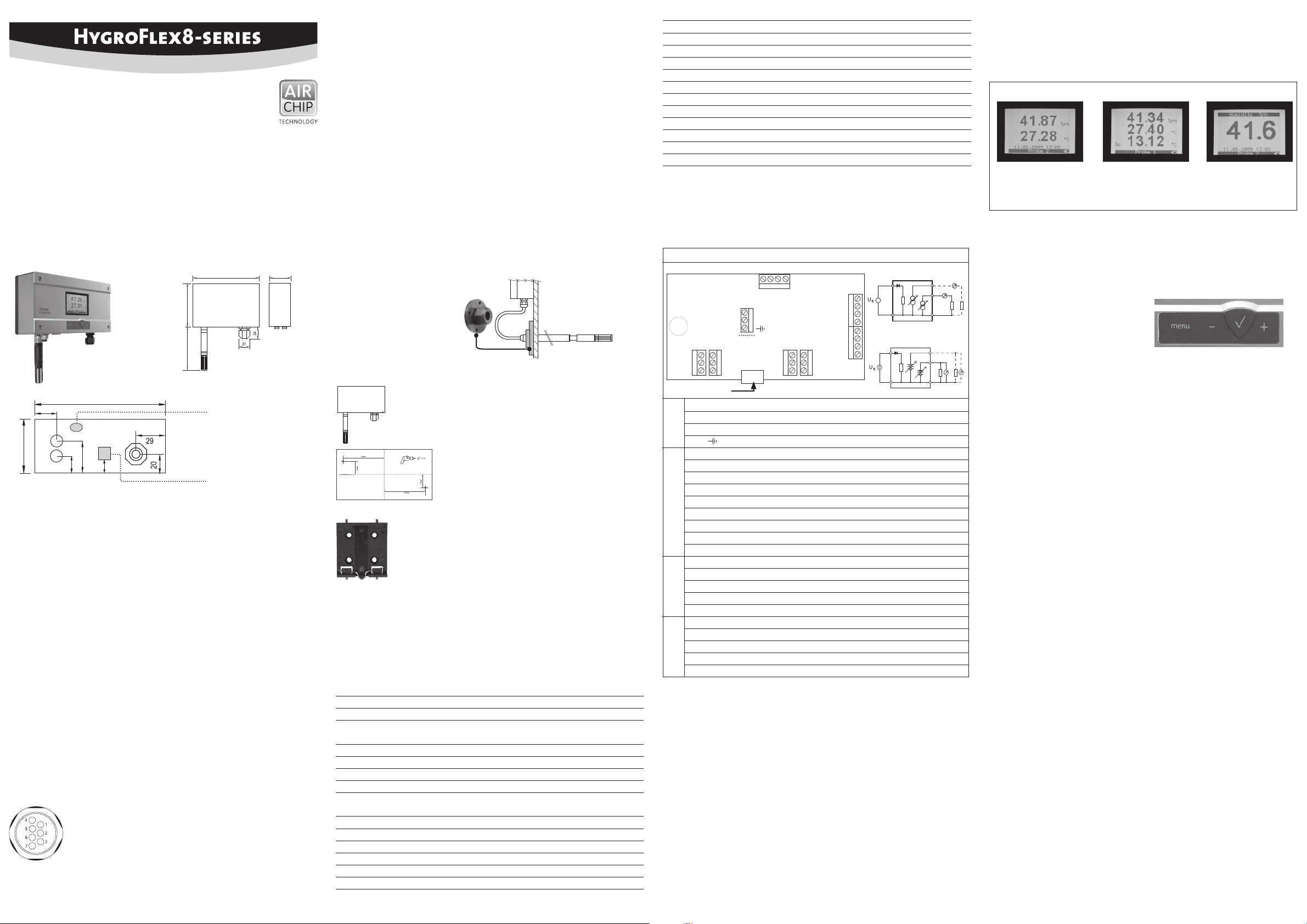
Display modes
The LC display has a backlight which can be set to be on all the time or whenever a key is pressed.
The backlight can also be disabled.
Using the HF8 Menu > Device Settings > Display Settings, the display mode can be changed as
shown below:
Standard 3-line display Large
%RH
Temperature
Date and time
%RH
Temperature
Calculated parameter
No date and time
Both the parameter and
probe can be changed
with the UP arrow key or
the DOWN arrow key
The display can also be congured to show a trend indicator on each line:
▲ increasing value ▼ decreasing value
In the event of an alarm the symbol [ ! ] appears to the right of the value.
The bottom of the display shows the date and time as well as which probe is currently selected.
Keypad
MENU
Activates the internal menu. Press this key
again to go back to the previous menu or to
exit the menu.
ENTER ✔
• When the menu is active, use to conrm the
selection of a menu item, effect a change of
settings and conrm any change.
• In the HF8 Standard Mode, use to capture the
current %RH and temperature data to one of
8 data bins.
Unit system
Press the MENU key and select Device Settings > Local Settings > Unit Sys. Press ENTER to activate
the Unit Sys menu item, use the [+] or [-] key to change the unit system. Press ENTER to conrm
and press MENU to exit.
The HW4 software can also be used to change the unit system.
Date and time
Press the MENU key and select Device Settings > Date or Time. Press ENTER to activate either
the Date or the Time menu item. Use the [+] or [-] key to change the Date or the Time. After each
change, the cursor moves to the right. When done, press ENTER to conrm and press MENU to exit.
To change either the date or the time format, Press the MENU key and select Device Settings >
Local Settings > Date Fmt or Time Fmt. Press ENTER to activate either the Date Fmt or the Time Fmt
menu item, use the [+] or [-] key to change the Date or the Time format. When done, press ENTER
to conrm and press MENU to exit.
The HW4 software can also be used to set the clock of the HF8 to the PC date and time.
Select the calculated parameter for a probe input
The calculated parameter is available only when the input is set for a digital HygroClip 2 probe.
Press the MENU key and select Device Settings > Input 1 or Input 2 > Calc. Press ENTER to activate
the Calc sub-menu, use the [+] or [-] key to select the calculated parameter. Press ENTER to conrm
and press MENU to exit.
ROTRONIC AG, CH-8303 Bassersdorf
Tel. +41 44 838 11 44, www.rotronic.com
ROTRONIC Messgeräte GmbH, D-76275 Ettlingen
Tel. +49 7243 383 250, www.rotronic.de
ROTRONIC SARL, 56, F - 77183 Croissy Beaubourg
Tél. +33 1 60 95 07 10, www.rotronic.fr
ROTRONIC Italia srl
, I- 20157 Milano
Tel. +39 2 39 00 71 90, www.rotronic.it
ROTRONIC Instruments (UK) Ltd, West Sussex RH10 9EE
Phone +44 1293 571000, www.rotronic.co.uk
ROTRONIC Instrument Corp, NY 11788, USA
Phone +1 631 427-3898, www.rotronic-usa.com
ROTRONIC South East Asia Pte Ltd, Singapore 339156
Phone +65 6294 6065, www.rotronic.com.sg
ROTRONIC Shanghai Rep. Office, Shanghai 200233, China
Phone +86 40 08162018, www.rotronic.cn
UP / DOWN + / –
• Changes either the probe or the parameter
being displayed (including the delta probe).
• When the menu is active, use to navigate the
menu, make a selection or change a value.
12.0902.0003
Page 2
KURZBEDIENUNGSANLEITUNG
Digitaler Messumformer für Feuchte- und Temperatur
Herzlichen Glückwunsch zum Kauf Ihres neuen HygroFlex8-Serie Messumformers. Sie haben damit
ein dem neuesten Stand der Technik entsprechendes Gerät erworben. Bitte lesen Sie diese KurzAnleitung genau durch, bevor Sie das Gerät installieren.
Allgemeine Beschreibung
Die HygroFlex8-Serie sind universelle Messumformer, mit auswechselbaren HC2-Fühlern, für die
Übertragung von Feuchte- und Temperaturmesswerten. Diese Kurzbedienungsanleitung beschränkt
sich auf die Beschreibung der wichtigsten Funktionen und der Installation des Gerätes. Die detaillierte Bedienungsanleitung nden Sie im Internet unter: www.rotronic.com
Abmessungen / Anschlüsse
192
102
85
192
31
Service Schnittstelle
52
39.5
22.3
16
Digitaler Anschluss
Gemessene Parameter
HygroClip2 Fühler:
Feuchte und Temperatur. Die Standard HC2-Fühler messen relative Feuchte mit einem kapazitiven
ROTRONIC Hygromer® IN1 Sensor und die Temperatur mit einem Pt100.
Analoger Eingang:
Es kann jeder Parameter eines Dritt-Anbieter-Sensors gemessen werden. Das analoge Signal
muss jedoch in den vorgegebenen Limits sein. Die Einheit kann über die HW4 > Gerätemanager >
Einheiten eingestellt werden. Analoger Druckfühler Eingang. Die Einheit kann über die HW4 >
Gerätemanager > Einheiten eingestellt werden.
Fühler Anschlüsse
Der HF8 hat zwei Fühler Eingänge welche mit Hilfe der HW4-Software (Gerätemanager) wie folgt
eingestellt werden können:
HygroClip2 Feuchte-/ Temperatur Digital Fühler (Standard):
Beide Eingänge können so konguriert werden, dass das digitale Signal der HygroClip2 Fühler
gelesen und angezeigt werden kann.
1-Kanal-Analog Fühlereingang:
Pro Fühlereingang kann ein analoges Signal eingelesen werden. Für den analogen Eingang gelten
folgende Werte: Spannungsversorgung max 5 VDC, Stromaufnahme des angeschlossenen Fühlers
max 10mA, Analoger Eingang 0...3.3 VDC. Ein 12-bit A/D Wandler bereitet das Signal auf.
Analoger Druckfühler Eingang:
Es gelten dieselben Vorgaben wie beim 1-Kanal Analog-Fühlereingang, zusätzlich wird der
eingelesene Druckwert für die Berechnung von Feuchte-Parameter, welche Druck verwenden,
mit einbezogen.
Pin-Belegung
1) RXD (UART - Digitaler Fühler)
2) GND (digital und Speisung)
3) V+: digitaler Fühler: 3.3 VDC nominal, analoger Fühler:
max. 5.0 VDC, 10mA
4) AGND (analog Ground)
5) nicht verwendet
6) 1-Kanal analoger Fühler Signal: +0.0 bis 3.3 VDC
7) TXD (UART - Digital Fühler)
52
Mechanische Installation
Allgemeine Empfehlungen
Die relative Feuchte ist extrem temperaturabhängig. Deren exakte Messung erfordert, dass Fühler
und Sensoren genau auf dem Temperaturniveau der zu messenden Umgebung sind. Daher kann
der gewählte Installationsort einen bedeutenden Einuss auf die Leistung des Gerätes haben.
Die Einhaltung der folgenden Richtlinien garantiert Ihnen eine optimale Leistung des Gerätes:
a) Wählen Sie einen repräsentativen Installationsort: installieren Sie den Fühler an einem Ort, wo die
Feuchte- Temperatur- und Druckverhältnisse für die zu messende Umgebung repräsentativ sind.
b) Stellen Sie genügend Luftbewegung am Fühler sicher: Eine Luftgeschwindigkeit von mindestens
1 Meter/Sekunde beschleunigt und erleichtert die Anpassung des Fühlers an wechselnde
Temperaturen.
c) Zu vermeiden sind:
1. Fühler zu nahe an Heizelement, Kühlschlange, kalter oder warmer Wand, direkte Sonneneinstrahlung etc.
2. Fühler zu nahe an Dampf- Injektor, Befeuchter, oder direkter Niederschlag.
3. Unstabile Druckverhältnisse bei grossen Luftturbulenzen.
d) Tauchen Sie den Fühler so weit als möglich in die zu messende Umgebung ein.
e) Vermeiden Sie die Ansammlung von Kondensat an den Kontaktdrähten des Sensors. Instal-
lieren Sie den Fühler so, dass die Fühlerspitze nach unten zeigt. Wenn dies nicht möglich ist,
installieren Sie ihn in horizontaler Position.
Montage mit abgesetztem Fühler
Zur Vermeidung von Messfehlern sollten mindestens 200 mm des Fühlers in die zu messende
Umgebung eingetaucht sein. Verwenden Sie gegebenenfalls den Montageansch AC5005 um
den Fühler zu installieren.
AC5005 Montageansch
für 15mm Fühler
Montage der Wandversion
Ausrichtung
Der Transmitter wird so montiert, dass der Fühler
nach unten gerichtet ist.
Montage Variante 1
Mit der auf der Verpackung aufgezeichneten Bohrschablone werden
die nötigen Löcher gebohrt. Danach werden die mitgelieferten
Dübel eingesetzt um dann den Transmitter mit Hilfe der Schrauben
zu montieren.
Montage Variante 2
Bei vorhanden DIN-Hutschienen TS35 kann unter Mithilfe des
Montagekit AC5002 (optional erhältlich) der Transmitter direkt
auf die DIN Hutschienen aufgeschnappt werden. Hierzu werden
die DIN-Halterungen (Eine Verpackungseinheit besteht aus 2
Halterungen und 8 Schrauben) direkt auf die vorgebohrten Löcher
des Transmitters geschraubt.
Elektrische Installation
Stromversorgung
a) HF831 - HF835: 15 bis 40 VDC oder 12 bis 28 VAC
b) HF841 - HF845 (galvanisch getrennt): 9 bis 36 VDC oder 7 bis 24 VAC
c) HF857: Power over Ethernet (PoE) oder 12 bis 28 VAC
d) HF861 - HF865: 85 bis 265 VAC
Bemerkung:
Abhängig vom Ausgangssignal, kann der HF8 mit folgenden Minimal Spannungen betrieben werden
0…1 V Ausgänge 5 VDC oder 5 VAC
0…5 V Ausgänge 10 VDC oder 8 VAC
0…20 mA or 4 …20 mA Ausgänge 6 VDC oder 5 VAC mit 0 Ohm Last
15 VDC oder 12 VAC mit 500 Ohm Last
Maximale Stromaufnahme
Modell mit 4 Analogausgängen: 150 mA
Modell mit 4 Relais Kontakten: 150 mA
Modell mit Ethernet (TCP/IP): 300 mA
Supply voltage / Technology
Typ Versorgungsspannung V+ Bürde Ausgang
HF831 15…40 VDC / 12…28 VAC Max 500 Ω 0...20 mA
HF832 15…40 VDC / 12…28 VAC Max 500 Ω 4...20 mA
HF833 15…40 VDC / 12…28 VAC Min 1000 Ω 0...1 V
HF834 15…40 VDC / 12…28 VAC Min 1000 Ω 0...5 V
HF835 15…40 VDC / 12…28 VAC Min 1000 Ω 0...10 V
Typ Versorgungsspannung V+ Bürde Ausgang
HF841 9…36 VDC / 7…24 VAC Max 500 Ω 0...20 mA
HF842 9…36 VDC / 7…24 VAC Max 500 Ω 4...20 mA
HF843 9…36 VDC / 7…24 VAC Min 1000 Ω 0...1 V
HF844 9…36 VDC / 7…24 VAC Min 1000 Ω 0...5 V
HF845 9…36 VDC / 7…24 VAC Min 1000 Ω 0...10 V
HF857 Power over Ethernet (PoE) Digitaler Ausgang
HF861 85...265VAC Max 500 Ω 0...20 mA
HF862 85...265VAC Max 500 Ω 4...20 mA
HF863 85...265VAC Min 1000 Ω 0...1 V
HF864 85...265VAC Min 1000 Ω 0...5 V
HF865 85...265VAC Min 1000 Ω 0...10 V
Achtung: Falsche Versorgungsspannungen sowie zu grosse Belastungen der Ausgänge
A
können den Messumformer beschädigen.
Klemmenbelegung / Anschlussschemata
Anhand der Tabelle Versorgungsspannung / Technologie wird der Typ deniert, um folgende
Anschluss-Schemas verwenden zu können:
Anschlussklemmen Diagramm (alle HF8 Modelle)
Stromausgang
K6-2:
DC+/AC L
K 1
1
~
=
2
3
K6-1:
4
DC −/AC N
1
2
3
4
K 2
K6-2:
DC+/AC L
K6-1:
DC −/AC N
Spannungsausgang
K2: OUT2...4
K2: OUT1
K1: GND
K2: OUT2...4
K2: OUT1
K1: GND
K 4
K 5
3
COM
NO
NC
3
2
2
1
1
digital in/output
NO
COM
NC
K6
• •
B2
DC–/AC N
1
2
DC+/AC L
3
123
V+
GND
NO
COM
NC
485+
3
2
1
K 3
4
485–
K 7
K8
GND
GND
GND
GND
OUT1
OUT2
OUT3
OUT4
NO
3
COM
2
NC
1
Klemme K6 Beschreibung
K6-1: – Spannungsversorgung: VDC (-) or VAC (Neutral)
K6-2: + Spannungsversorgung: VDC (+) or VAC (Phase)
Spannungs-
versorgung
K6-3: Erde (siehe Bemerkung unten)
Klemme K1 und K2 Beschreibung Standard output
K1-1: GND Ausgang Signal 1 (–)
K1-2: GND Ausgang Signal 2 (–)
K1-3: GND Ausgang Signal 3 (–)
K1-4: GND Ausgang Signal 4 (–)
K2-1: OUT 1 Ausgang Signal 1 (+) Feuchte*
K2-2: OUT 2 Ausgang Signal 2 (+) Temperatur**
K2-3: OUT 3 Ausgang Signal 3 (+) Feuchte*
K2-4: OUT 4 Ausgang Signal 4 (+) Temperatur**
Klemme K3 (RS-485) Beschr eibu ng
K3-1: V+
K3-2: GND
VDC (+), wenn HF8 durch RS-485 Daten Kabel betrieben wird
VDC (–),wenn HF8 durch RS-485 Daten Kabel betrieben wird
K3-3: D+ RS-485 +
K3-4: D– RS-485 –
Relais 1 2 3 4
Klemme K7 K8 K4 K5
NC: im Ruhezustand geschlossen K7-1 K8-1 K4-1 K5-1
Relais Digital Analogaugänge
COM K7-2 K8-2 K4-2 K5-2
NO: im Ruhezustand geöffnet K7-3 K8-3 K4-3 K5-3
* Für Ausgangsparameter Feuchte & Berechnung:
OUT2/4 = berechneter Wert, OUT1/3 = Feuchte
** Für Ausgangsparameter Temperatur & Berechnung:
OUT1/3 = berechneter Wert, OUT2/4 = Temperatur
Klemme K6-3: Erde ist standardmässig mit GND verbunden. Wird das nicht gewünscht, muss auf
dem PCB (B2) eine Drahtbrücke entfernt werden.
Klemmen K3 (RS-485): Klemmen K3-1 und K3-2 können verwendet werden, um das Gerät zu
speisen (Mehrpunktverbindung). Es können mehrere RS-485 Geräte mit einem starken Netzgerät
15 VDC betrieben werden. In diesem Falle wird die Spannungsversorgung an K6-1 bis K6-3 nicht
verwendet.
Warnung: Stellen Sie sicher, dass, bevor Sie den Transmitter ins Netzwerk einbinden und anschliessen, alle Einstellungen richtig durchgeführt wurden.
Programmierung
Die Grundeinstellungen der Geräte werden im Werk, gemäss Ihrer Bestellung, vorgenommen.
Die Transmitter werden im Werk justiert, sodass eine Überprüfung oder Nachjustierung bei
der Installation nicht notwendig ist. Die Geräte können sofort nach der Installation in Betrieb
genommen werden.
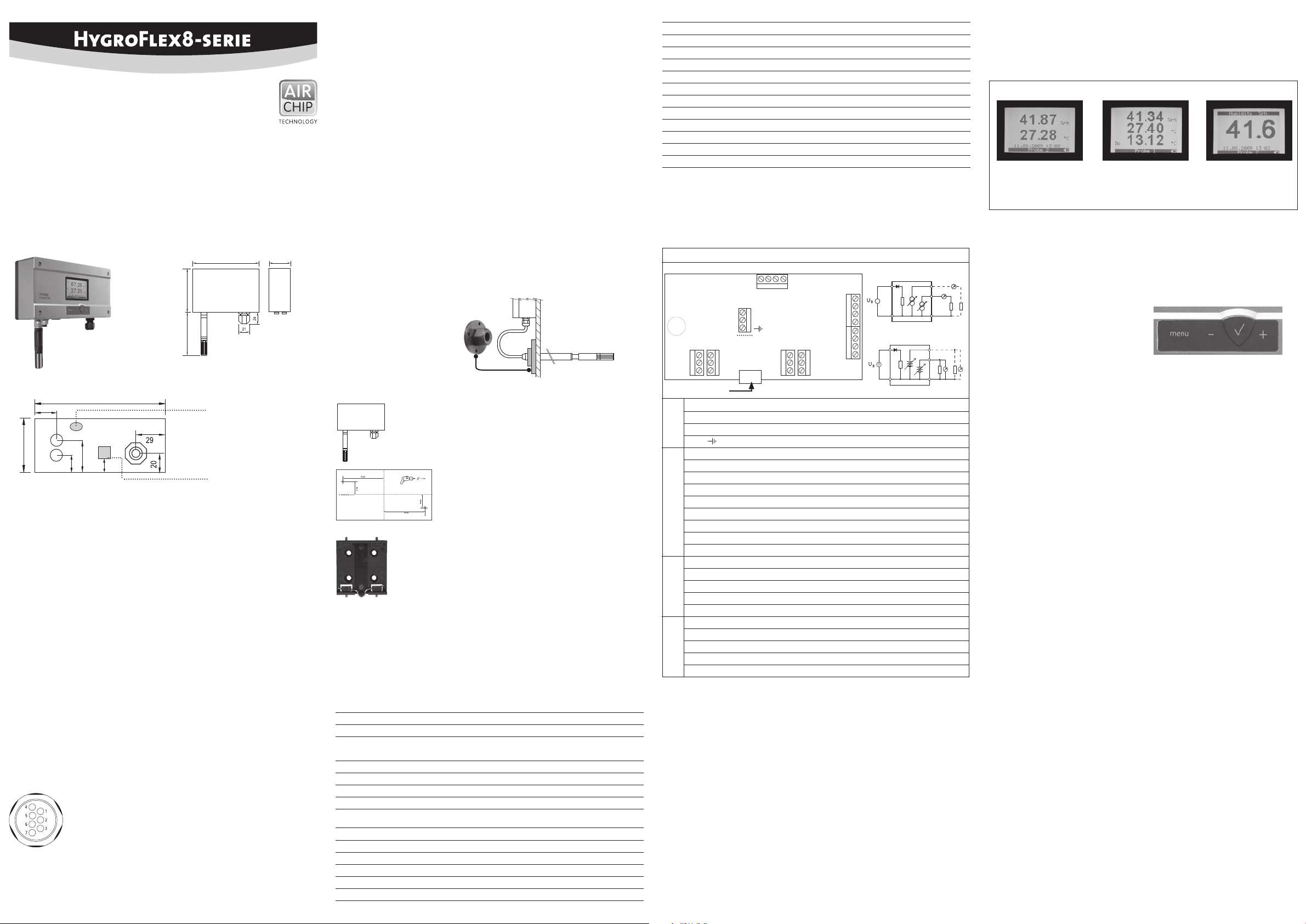
Display / Anzeigemodus
Das LC-Display hat eine Hintergrundbeleuchtung welche so eingestellt werden kann, dass diese
entweder immer an, immer aus ist oder durch drücken einer Taste kurzzeitig aktiviert wird.
Die Einstellungen erfolgen im HF8 Menu > Device Settings > Display Settings. Im selben Menü kann
der Anzeigemodus eingestellt werden.
Standard 3-Linien Gross
%rF
Temperatur
Datum und Zeit
%rF
Temperatur
Berechneter Wert
Beides, der angezeigte
Wert sowie der Fühler
kann mit den ▲ und ▼
geändert werden
Im Display kann zusätzlich ein Trend-Indikator für jeden Wert angezeigt werden:
▲ Steigender Wert ▼ Sinkender Wert
Bei einem Alarm wird das Symbol [ ! ] im rechten Displayrand angezeigt.
Im unteren Teil des Displays wird das Datum, die Zeit und welcher Fühler ausgewählt ist, angezeigt.
Ein Disketten Symbol erscheint wenn die Funktion Daten Loggen aktiviert ist.
Tatstaur
MENU
Aktiviert das interne Menü. Durch nochma-
liges drücken gelangt man ins nächst höhere
Menü/verlässt das Menü.
ENTER ✔
• Ist das Menü aktiviert wird die Entertaste
für die Auswahl der Untermenüs und zur
Bestätigung von Änderungen verwendet.
• Im HF8 Standard Mode: Zur Speicherung
der aktuellen Werte.
Systemeinheiten
Unter Menu/Device Settings > Local Settings > Unit System kann mit Hilfe der AUF/AB-Pfeile die
Einheit (Metrisch/Englisch) ausgewählt werden. Durch drücken der ENTER-Taste wird die Auswahl
übernommen. Dies kann auch mit Hilfe der HW4-Software bewerkstelligt werden.
Datum und Zeit
Unter MENU/Device Settings > Date or Time wird durch die ENTER-Taste entweder die Zeit oder das
Datum ausgewählt. Mit den AUF/AB-Tasten werden die Werte geändert und mit ENTER bestätigt.
Nach jeder Änderung, bewegt sich der Cursor nach rechts. Das Datum/Zeit Anzeigeformat kann
unter Device Settings > Local Settings > Date Fmt or Time Fmt geändert werden. Ebenfalls kann die
HW4 zur Änderung der Datum und Zeit Einstellungen verwendet werden.
Auswahl des kalkulierten Wertes für einen Fühlereingang
Die kalkulierten Parameter können nur bei Anschluss eines HygroClip2 Fühlers ausgewählt werden.
Unter MENU/ Device Settings > Input 1 oder Input 2 > Calc. ENTER wird mit den AUF-/AB-Tasten der
kalkulierte Wert ausgewählt und mit ENTER bestätigt.
ROTRONIC AG, CH-8303 Bassersdorf
Tel. +41 44 838 11 44, www.rotronic.com
ROTRONIC Messgeräte GmbH, D-76275 Ettlingen
Tel. +49 7243 383 250, www.rotronic.de
ROTRONIC SARL, 56, F - 77183 Croissy Beaubourg
Tél. +33 1 60 95 07 10, www.rotronic.fr
ROTRONIC Italia srl
, I- 20157 Milano
Tel. +39 2 39 00 71 90, www.rotronic.it
ROTRONIC Instruments (UK) Ltd, West Sussex RH10 9EE
Phone +44 1293 571000, www.rotronic.co.uk
ROTRONIC Instrument Corp, NY 11788, USA
Phone +1 631 427-3898, www.rotronic-usa.com
ROTRONIC South East Asia Pte Ltd, Singapore 339156
Phone +65 6294 6065, www.rotronic.com.sg
ROTRONIC Shanghai Rep. Office, Shanghai 200233, China
Phone +86 40 08162018, www.rotronic.cn
AUF / AB + / –
• Wechselt entweder den Fühler oder den
Parameter welcher angezeigt wird
• Ist das Menü aktiviert, werden die
+/– Tasten zur Navigation, zur Änderung
von Parametern und Werten verwendet.
12.0902.0003
Page 3

MODE D'EMPLOI ABRÉGÉ
Transmetteur de mesure numérique
pour humidité & température
Nous vous félicitons d’avoir choisi le nouveau transmetteur de la série HygroFlex8, doté de la
technologie la plus récente pour ce type d’appareil. Nous vous remercions de lire ce mode d’emploi
avant d’installer votre transmetteur.
Description générale
Les appareils de la série HygroFlex8 sont des transmetteurs de mesure universels pour la
transmission de valeurs de mesure d’humidité et de température. Compatible avec tous les
capteurs interchangeables HC2. Ce mode d’emploi abrégé se limite à la description des fonctions
essentielles de cet appareil. Vous trouverez un mode d’emploi détaillée sur notre site Internet:
www.rotronic.com
Dimensions / raccordements
192
102
85
192
31
Interface de service
52
39.5
22.3
16
Raccordement numérique
Paramètres mesurés
Capteur HygroClip2: humidité et température. Les capteurs standards HC2 utilisent un élément sensible capacitif ROTRONIC Hygromer
®
IN1 pour l’humidité relative et un Pt100 pour la température.
Entrée analogique: tous les paramètres des éléments sensibles des fabricants tiers peuvent être
mesurés. Le signal analogique doit toutefois ne pas dépasser les valeurs limites. L’unité peut être
réglée par HW4 > gestionnaire d’appareils > Unités. Entrée analogique pour capteur: l’unité peut
être réglée par HW4 > gestionnaire d’appareils > Unités.
Capteur raccordement
L’HF8 est équipé de deux entrées pour capteurs qui peuvent être paramétrées à l’aide du logicielHW4 (gestionnaire d’appareils) de la manière suivante:
Capteur numérique HygroClip2 pour humidité et température (standard):
Les deux entrées peuvent être congurées de manière à ce que les signaux numériques de
l’Hygroclip2 puissent être lus et afchés.
Entrée analogique à 1 canal pour capteur:
Un seul signal analogique par canal peut être reçu. Les valeurs suivantes doivent être respectées
pour les entrées analogiques: tension d’alimentation max 5 VCC, consommation du capteur relié
max 10mA, entrée analogique 0...3,3 VCC. Un convertisseur 12-bit A/D assure le traitement du
signal.
Entrée analogique pour capteur de pression:
Les consignes à respecter sont les mêmes que pour l’entrée analogique à un canal, mais la valeur
de pression reçue est utilisée pour le calcul de paramètres d’humidité qui utilisent cette donnée.
any humidity parameter that requires barometric pressure as an input value (example: mixing ratio).
Affectation des bornes
1) RXD (UART – capteur numérique)
2) GND (numérique et alimentation)
3) V+: capteur numérique: 3,3 VDCC nominal,
capteur analogique: max. 5,0 VCC, 10mA
4) AGND (terre analogique)
5) Inutilisé
6) Signal de capteur analogique à 1 canal: +0,0 à 3,3 VCC
7) TXD (UART – capteur numérique)
52
Installation mécanique
Recommandations générales
L’humidité relative dépend très fortement de la température. Pour la précision de sa mesure, le
capteur et les éléments sensibles doivent être réglés exactement sur le niveau de température de
l’environnement à mesurer. Le site d’installation choisi peut ainsi avoir une inuence décisive sur
les performances de l’appareil. Le respect des directives suivantes vous garantit des performances
optimales de l’appareil:
a) Choisissez un site d’installation représentatif : installez le capteur à un endroit où les conditions
d’humidité, de température et de pression sont représentatives de l’environnement à mesurer.
b) Assurez un mouvement d’air sufsant près du capteur : une vitesse d’air d’au moins 1 mètre/
seconde accélère et facilite l’adaptation du capteur aux températures changeantes.
c) À éviter:
1. Capteur trop près d’éléments de chauffage, serpentins de refroidissement, mur froid ou
chaud, exposition directe aux rayons solaires etc.
2. Capteur trop proche de vapeur, d’un injecteur, d’un humidicateur ou de précipitations
directes.
3. Conditions de pression instables en cas de fortes turbulences d’air.
d) Le capteur aussi loin que possible dans l’environnement à mesurer.
e) Évitez les accumulations de condensation sur les ls de contact de l’élément sensible. Installez
le capteur de telle sorte que la pointe du capteur soit dirigée vers le bas. Si cela n’est pas
possible, installez-le à l’horizontale.
Montage avec un capteur séparé
Pour éviter les erreurs de mesure, au moins 200 mm du capteur doivent être plongés dans l’environnement à mesurer. Utilisez le cas échéant la bride de montage AC5005 pour installer le capteur.
AC5005 Bride de montage
pour capteur 15mm
Montage de la version murale
Orientation
Le transmetteur de mesure doit être monté de telle sorte que le
capteur soit orienté vers le bas.
Variante 1 de montage
Utiliser le gabarit de perçage tracé sur l’emballage pour percer les
trous nécessaires. Ensuite, mettre en place les chevilles fournies
pour monter le transmetteur de mesure à l’aide des vis.
Variante 2 de montage
Si des embases de rail DIN TS35 sont déjà en place, il est possible
de clipser directement le transmetteur sur les embases de rail DIN
à l’aide du kit de montage AC5002 (disponible en option). Pour
cela, visser les xations DIN (une unité d’emballage se compose
de 2 xations et 8 vis) directement sur les trous pré-percés du
transmetteur de mesure.
Installation électrique
Alimentation électrique
a) HF831 - HF835: 15 à 40 VCC ou 12 à 28 VCA
b) HF841 - HF845 (séparation galvanique): 9 à 36 VCC ou 7 à 24 VCA
c) HF857: Power over Ethernet (PoE) or 12 to 28 VCA
d) HF861 - HF865: 85 à 265 VCA
Remarque
Dépendant du signal de sortie, le HF8 peut fonctionner avec la tensionminimale suivante
0…1 V sorties 5 VCC ou 5 VCA
0…5 V sorties 10 VCC ou 8 VCA
0…20 mA ou 4 …20 mA sorties 6 VCC ou 5 VCA avec 0 Ohm charge
15 VCC ou 12 VCA avec 500 Ohm charge
Consommation maximale en courant
Model avec 4 sorties analogiques 150 mA
Model avec 4 relais contact 150 mA
Model avec Ethernet (TCP/IP) 300 mA
Tension d’alimentation / technologie
Type Alimentation en tension V+ Charge Sortie
HF831 15…40 VCC / 12…28 VCA Max 500 Ω 0...20 mA
HF832 15…40 VCC / 12…28 VCA Max 500 Ω 4...20 mA
HF833 15…40 VCC / 12…28 VCA Min 1000 Ω 0...1 V
HF834 15…40 VCC / 12…28 VCA Min 1000 Ω 0...5 V
HF835 15…40 VCC / 12…28 VCA Min 1000 Ω 0...10 V
Type Alimentation en tension V+ Charge Sortie
HF841 9…36 VCC / 7…24 VCA Max 500 Ω 0...20 mA
HF842 9…36 VCC / 7…24 VCA Max 500 Ω 4...20 mA
HF843 9…36 VCC / 7…24 VCA Min 1000 Ω 0...1 V
HF844 9…36 VCC / 7…24 VCA Min 1000 Ω 0...5 V
HF845 9…36 VCC / 7…24 VCA Min 1000 Ω 0...10 V
HF857 Power over Ethernet (PoE) Digital Output
HF861 85...265 VCA Max 500 Ω 0...20 mA
HF862 85...265 VCA Max 500 Ω 4...20 mA
HF863 85...265 VCA Min 1000 Ω 0...1 V
HF864 85...265 VCA Min 1000 Ω 0...5 V
HF865 85...265 VCA Min 1000 Ω 0...10 V
Attention: Des tensions d’alimentation erronées ainsi que des sollicitations trop fortes
A
des sorties peuvent endommager le transmetteur de mesure.
Affectation des bornes / schémas de raccordement
Le tableau de tension d’alimentation / technologie sert à dénir le type pour pouvoir utiliser les
schémas de raccordement suivants:
Terminal block diagram (all HF8 models)
Sortie de courant
K6-2:
DC+/AC L
K 1
~
1
=
2
3
K6-1:
4
DC −/AC N
1
2
3
4
K 2
K6-2:
DC+/AC L
K6-1:
DC −/AC N
Sortie de tension
K2: OUT2...4
K2: OUT1
K1: GND
K2: OUT2...4
K2: OUT1
K1: GND
K 4
K 5
3
COM
NO
NC
3
2
2
1
1
digital in/output
NO
COM
NC
K6
• •
B2
DC–/AC N
1
2
DC+/AC L
3
123
V+
GND
NO
COM
NC
485+
3
2
1
K 3
4
485–
K 7
K8
GND
GND
GND
GND
OUT1
OUT2
OUT3
OUT4
NO
3
COM
2
NC
1
Borne K6 Description
K6-1: – Alimentation en tension: VCC (-) or VCA (neutre)
K6-2: + Alimentation en tension : VCC (+) ou VCA (phase)
Alimentation
en tension
K6-3: Terre (Voir les remarques ci-dessous)
Borne K1 et K2 Description Sortie standard
K1-1: GND Signal de sortie 1 (–)
K1-2: GND Signal de sortie 2 (–)
K1-3: GND Signal de sortie 3 (–)
K1-4: GND Signal de sortie 4 (–)
K2-1: OUT 1 Signal de sortie1 (+) Humidité*
K2-2: OUT 2 Signal de sortie 2 (+) Température**
K2-3: OUT 3 Signal de sortie 3 (+) Humidité*
K2-4: OUT 4 Signal de sortie 4 (+) Température**
Borne K3 (RS-485) Desc ript ion
K3-1: V+ VCC (+), si le HF8 fonctionne avec un RS-485 câble de données
K3-2: GND VCC (-), si le HF8 fonctionne avec un RS-485 câble de données
K3-3: D+ RS-485 +
K3-4: D– RS-485 –
Relais 1 2 3 4
Borne K7 K8 K4 K5
NC: Au repos fermé K7-1 K8-1 K4-1 K5-1
Relais Numérique Analogue
COM: Commun raccordement K7-2 K8-2 K4-2 K5-2
NO: Au repos ouvert K7-3 K8-3 K4-3 K5-3
* Les sorties pour humidité et valeur calculée:
OUT2/4 = valeur calculée, OUT1/3 = humidité
** Les sorties pour température et valeur calculée:
OUT1/3 = valeur calculée, OUT2/4 = température
Borne K6-3: par défaut, la terre est connectée à GND. Si cela n'est pas souhaité, il faut enlever
un pont enchable sur la carte (B2) de circuit imprimé.
Bornes K3 (RS-485): les bornes K3-1 et K3-2 peuvent être utilisées pour l’alimentation de
l’appareil (connexion sur plusieurs points). Il est possible d’utiliser plusieurs appareils RS-485
avec un appareil d’alimentation 15VDC puissant. Dans ce cas, l’alimentation en tension sur K6-1
à K6-3 n’est pas utilisée.
Attention: avant d’intégrer le transmetteur de mesure au réseau et le raccorder, assurez-vous
d’avoir correctement effectué tous les réglages.
Programmation
Les réglages de base des appareils sont effectués dans l’usine conformément à votre commande.
Les transmetteurs de mesure sont ajustés en usine. De fait, une vérication ou réajustement de
l’installation n’est pas nécessaire. Les appareils peuvent être mis en service immédiatement
après l’installation.
Afchage / modes d’afchage
L’écran LC est équipé d’un dispositif de rétro éclairage qui peut être paramétré de façon à être
toujours en service, désactivé ou activé par courte pression d’une touche. Les réglages sont
effectués dans le menu de l’HF8 Device Settings > Display Settings. Ce menu permet également
de sélectionner le mode d’afchage.
Standard 3 lignes Large
%HR
Température
Date et heure
%HR
Température
Valeur calculée
La valeur afchée ainsi
que le capteur peuvent
être modiés par les
touches ▲ et ▼
L’écran peut, de plus, afcher les indicateurs de n de mesure pour chaque valeur:
▲ Valeur croissante ▼ Valeur décroissante
En cas d’alarme, le symbole [ ! ] afché sur le côté droit de l’écran.
La date, l’heure et le capteur actuellement sélectionné sont indiqués au bas de l’écran. Une icône
de disque apparaît quand la fonction d'enregistrement des données est activée.
Touches de fonction
MENU
Active le menu interne. Pressions répétées
pour naviguer dans les menus d’un même
niveau ou quitter le menu actuel.
ENTER ✔
• Si le menu est activé, la touche ENTER sert à
sélectionner les sous-menus et à conrmer
les modications effectuées.
• Sur l’HF8 en mode standard:
pour l’enregistrement de la valeur actuelle.
Unités
Le menu Device Settings > Local Settings > Unit System, permet de sélectionner l’unité (métrique ou
anglaise) à l’aide des touches HAUT/BAS. Le choix est conrmé en appuyant sur la touche ENTER.
Ce réglage peut également être effectué par le logiciel HW4.
Date et heure
Le menu Device Settings > Date or Time, la touche ENTER permet de sélectionner la date ou l’heure.
Les touches HAUT/BAS permettent de modier ces valeurs puis de conrmer avec ENTER. Le curseur
se déplace vers la droite après chaque modication. Le réglage du format d’afchage de la date/
heure peut être paramétré sous le menu Device Settings > Local Settings > Date Fmt or Time Fmt. Le
logiciel HW4 peut également être utilisé pour effectuer les paramétrages de la date et de l’heure.
Choix de la valeur calculée pour une entrée de capteur
Les paramètres calculés ne peuvent être sélectionnés qu’en combinaison avec un capteur Hygro-
Clip2. Le menu Device Settings > Input 1 ou Input 2 > Calc. ENTER permet de sélectionner la valeur
calculée avec les touches HAUT/BAS avant de conrmer avec la touche ENTER.
ROTRONIC AG, CH-8303 Bassersdorf
Tel. +41 44 838 11 44, www.rotronic.com
ROTRONIC Messgeräte GmbH, D-76275 Ettlingen
Tel. +49 7243 383 250, www.rotronic.de
ROTRONIC SARL, 56, F - 77183 Croissy Beaubourg
Tél. +33 1 60 95 07 10, www.rotronic.fr
ROTRONIC Italia srl
, I- 20157 Milano
Tel. +39 2 39 00 71 90, www.rotronic.it
ROTRONIC Instruments (UK) Ltd, West Sussex RH10 9EE
Phone +44 1293 571000, www.rotronic.co.uk
ROTRONIC Instrument Corp, NY 11788, USA
Phone +1 631 427-3898, www.rotronic-usa.com
ROTRONIC South East Asia Pte Ltd, Singapore 339156
Phone +65 6294 6065, www.rotronic.com.sg
ROTRONIC Shanghai Rep. Office, Shanghai 200233, China
Phone +86 40 08162018, www.rotronic.cn
HAUT / BAS + / –
• Modie la sélection du capteur ou du paramètre destiné à être afché.
• Si le menu est activé, les touches +/– servent
à la navigation et aux changements des
paramètres et des valeurs.
12.0902.0003
Page 4

MANUALE D'ISTRUZIONI BREVE
Trasmettitore digitale per umidità e temperatura
Ci congratuliamo per il Vostro acquisto di un nuovo trasmettitore della Serie HygroFlex8. Avete
acquistato uno strumento al passo con le tecnologie più moderne. Prima di installare lo strumento,
si prega di leggere la presente guida rapida.
Descrizione generale
Gli apparecchi della Serie HygroFlex8 sono trasmettitori universali, per sonde intercambiabili
HC2, per la trasmissione di valori di umidità e temperatura. La presente guida rapida si limita
a descrivere le funzioni principali dello strumento e la sua installazione. Le istruzioni d’uso
dettagliate sono disponibili in Internet all’indirizzo: www.rotronic.com
Dimensioni / connessioni
192
102
85
192
31
Interfaccia di servizio
52
39.5
22.3
16
Connessione digitale
Parametri misurati
Sonda HygroClip2: umidità e temperatura. Le sonde HC2 standard misurano l’umidità relativa con
un sensore capacitivo ROTRONIC Hygromer
®
IN1 e la temperatura con una Pt100 RTD.
Sonda analogica: è misurabile ogni parametro di una sonda di produttori terzi. Il segnale analogico
deve però rientrare nelle speciche di seguito indicate.
Il parametro misurato deve essere impostato mediante il software HW4.
Sonda analogica di pressione: è possibile impostare l’ingresso mediante il software HW4.
Ingressi per le sonde
L’HF8 dispone di due ingressi sonda impostabili come segue mediante il software HW4
(Device Manager):
HygroClip2 sonda digitale per umidità e temperatura (standard):
possono congurare i due ingressi in modo che il segnale digitale delle sonde Hygroclip2 sia
letto e visualizzato.
Ingresso sonda analogica a 1 canale:
effettuare la lettura di un segnale analogico. Per l’ingresso analogico valgono i seguenti valori:
tensione di alimentazione max. 5 VDC, assorbimento di corrente della sonda collegata max. 10mA,
segnale acquisito 0...3,3 VDC. Un convertitore A/D a 12-bit elabora il segnale.
Entrata analogica sonda pressione:
valgono le stesse indicazioni come al punto precedente e inoltre il valore letto viene utilizzato per
il calcolo dei parametri di umidità assoluta che dipendono dalla pressione.
Corrispondenza pin
1) RXD (UART – sonda digitale)
2) GND (digitale e alimentazione)
3) V+: sonda digitale: 3.3 VDC nominale, sonda analogica: max. 5,0 VDC, 10mA
4) AGND (Ground analogico)
5) non utilizzato
6) segnale sonda analogica a 1 canale: da +0,0 a 3,3 VDC
7) TXD (UART – sonda digitale)
52
Installazione meccanica
Consigli generici
L’umidità relativa dipende direttamente dalla temperatura. La sua misurazione esatta richiede
che la sonda e i sensori abbiano esattamente la stessa temperatura dell’ambiente da misurare.
Pertanto la sede di installazione scelta ha un ruolo primario per il rendimento dello strumento.
Per ottenere un rendimento ottimale dello strumento si devono assolutamente rispettare le
seguenti prescrizioni:
a) Selezionare una sede di installazione rappresentativa per le misurazioni: installare la sonda
in un punto dove le condizioni di umidità, temperatura e pressione siano rappresentative per
l’ambiente che si intende misurare.
b) Garantire che la sonda sia sottoposta a sufciente ventilazione: Una velocità dell’aria di almeno
1 metro/secondo velocizza e facilita l’adattamento della sonda alle variazioni di temperatura.
c) Condizioni da evitare:
1. Sonda troppo vicina a elementi riscaldanti, serpentine di raffreddamento, pareti fredde o
calde, esposizione diretta ai raggi solari ecc.
2. Posizionamento della sonda troppo vicino a fonti di vapore, iniettori, umidicatori, spruzzi
d'acqua.
3. Condizioni di pressione instabile e/o eccessive turbolenze dell’aria.
d) Inserire il più possibile la sonda nell’ambiente che si intende misurare.
e) Evitare la formazione di condensa sulle gambe dei sensori. Installare la sonda in modo che la
punta sia rivolta verso il basso, nel caso non sia possibile, installarla in posizione orizzontale.
Montaggio con sonda separata
Per evitare possibili errori di misurazione, si dovrebbero inserire almeno 200 mm della sonda
nell’ambiente da misurare. Utilizzare eventualmente la angia di montaggio AC5005 per installare
la sonda.
Flangia di montaggio AC5005
per sonda da 15mm
Montage de la version murale
Orientamento
Il trasmettitore va montato in modo che la sonda sia rivolta verso
il basso.
Variante 1 di montaggio
Utilizzando la sagoma di foratura sulla confezione per effettuare i
fori necessari. In seguito si inseriscono i tasselli forniti per montare
il trasmettitore
Variante 2 di montaggio
Se sono presenti barre di montaggio DIN TS35, utilizzando il kit di
montaggio AC5002 (opzionale) è possibile montare il trasmettitore
direttamente sulle barre DIN. A tal scopo si avvitano i supporti
direttamente sui fori predisposti sul trasmettitore.
(una confezione AC5002 contiene 2 supporti e 8 viti).
Installazione elettrica
Tensione di Alimentazione
a) HF831 - HF835: 15 a 40 VDC oppure 12 a 28 VAC
b) HF841 - HF845 (con separazione galvanica): 9 a 36 VDC oppure 7 a 24 VAC
c) HF857: Alimentazione via Ethernet (PoE) oppure da 12 a 28 VAC
d) HF861 - HF865: da 85 a 265 VAC
Nota: in funzione dei segnali di uscita, l'HF8 dovrà essere alimentato con le seguenti tensioni di
alimentazioni minime:
Uscita 0…1 V 5 VDC o 5 VAC
Uscita 0…5 V 10 VDC o 8 VAC
Uscita 0…20 mA e 4 …20 mA 6 VDC o5 VAC con carico 0 ohm
15 VDC o 12 VAC con carico 500 ohm
Consumo massimo di corrente (tipico)
Modelli con 4 uscite analogiche 150 mA
Modelli con 4 contatti relé 150 mA
Modelli con interfaccia Ethernet (TCP/IP) 300 mA
Tensione di alimentazione / tecnologia
Tipo Tensione di Alimentazione V+ Carico Uscita
HF831 15…40 VDC / 12…28 VAC Max 500 Ω 0...20 mA
HF832 15…40 VDC / 12…28 VAC Max 500 Ω 4...20 mA
HF833 15…40 VDC / 12…28 VAC Min 1000 Ω 0...1 V
HF834 15…40 VDC / 12…28 VAC Min 1000 Ω 0...5 V
HF835 15…40 VDC / 12…28 VAC Min 1000 Ω 0...10 V
Tipo Tensione di Alimentazione V+ Carico Uscita
HF841 9…36 VDC / 7…24 VAC Max 500 Ω 0...20 mA
HF842 9…36 VDC / 7…24 VAC Max 500 Ω 4...20 mA
HF843 9…36 VDC / 7…24 VAC Min 1000 Ω 0...1 V
HF844 9…36 VDC / 7…24 VAC Min 1000 Ω 0...5 V
HF845 9…36 VDC / 7…24 VAC Min 1000 Ω 0...10 V
HF857 Alimentazione via Ethernet (PoE) Uscita digitale
HF861 85...265 VAC Max 500 Ω 0...20 mA
HF862 85...265 VAC Max 500 Ω 4...20 mA
HF863 85...265 VAC Min 1000 Ω 0...1 V
HF864 85...265 VAC Min 1000 Ω 0...5 V
HF865 85...265 VAC Min 1000 Ω 0...10 V
Attenzione: tensioni di alimentazione errate o carichi eccessivi sulle uscite possono
A
danneggiare il trasmettitore.
Morsettiere / schemi di collegamento
In base alla tabella “Tensione di alimentazione / tecnologia” si denisce il tipo di trasmettitore e
gli schemi di collegamento da utilizzare:
Schemi di collegamento (tutti modello HF8)
Uscita di corrente
K6-2:
DC+/AC L
K 1
~
1
=
2
3
K6-1:
4
DC −/AC N
1
2
3
4
K 2
K6-2:
DC+/AC L
K6-1:
DC −/AC N
Uscita di tensione
K2: OUT2...4
K2: OUT1
K1: GND
K2: OUT2...4
K2: OUT1
K1: GND
K 4
K 5
3
COM
NO
NC
3
2
2
1
1
digital in/output
NO
COM
NC
K6
• •
B2
DC–/AC N
1
2
DC+/AC L
3
123
V+
GND
NO
COM
NC
485+
3
2
1
K 3
4
485–
K 7
K8
GND
GND
GND
GND
OUT1
OUT2
OUT3
OUT4
NO
3
COM
2
NC
1
Morsetto K6 Descrizione
K6-1: – Alimentation en tension: VCC (-) or VCA (neutre)
K6-2: + Alimentation en tension : VCC (+) ou VCA (phase)
K6-3: Terre (Voir les remarques ci-dessous)
Tensione di
Alimentazione
Morsetto K1 e K2 Descrizione Uscita standard
K1-1: GND Segnale uscita 1 (–)
K1-2: GND Segnale uscita 2 (–)
K1-3: GND Segnale uscita 3 (–)
K1-4: GND Segnale uscita 4 (–)
K2-1: OUT 1 Segnale uscita1 (+) Umidità*
K2-2: OUT 2 Segnale uscita 2 (+) Temperatura**
K2-3: OUT 3 Segnale uscita 3 (+) Umidità*
K2-4: OUT 4 Segnale uscita 4 (+) Temperatura**
Morsetto K3 (RS-485) Des crizi one
K3-1: V+ VDC (+), quando l'HF8 é alimentato da cavo dati RS-485
K3-2: GND VDC (–), quando l'HF8 é alimentato da cavo dati RS-485
K3-3: D+ RS-485 +
K3-4: D– RS-485 –
Relé 1 2 3 4
Borne K7 K8 K4 K5
NC: Normalmente Chiuso (relé non energizzato) K7-1 K8-1 K4-1 K5-1
Relé Digitale Analogica
COM: Comune/Massa K7-2 K8-2 K4-2 K5-2
NO: Normalmente Aperto (relé non energizzato) K7-3 K8-3 K4-3 K5-3
* Per congurazione uscita umidità e valore calcolato:
OUT2/4 = valore calcolato, OUT1/3 = umidità
** Per congurazione uscita temperatura e valore calcolato:
OUT1/3 = valore calcolato, OUT2/4 = temperatura
Morsetto K6-3: La terra non è collegata come standard a GND. Se non necessario, chiudere il
cavallotto (B2) sulla scheda con una saldatura.
Morsetti K3 (RS-485): per alimentare lo strumento (in connessione multipla) si possono utiliz-
zare i morsetti K3-1 e K3-2 Si possono far funzionare diversi strumenti RS-485 utilizzando un
alimentatore potente da 15VDC. In tal caso l’alimentazione su K6-1 e K6-3 non viene utilizzata.
Avviso: prima di inserire il trasmettitore in rete e di collegarlo, assicurarsi di aver effettuato
correttamente tutte le impostazioni.
Programmazione
Le impostazioni base dello strumento sono effettuate in fabbrica, in conformità con il Vs. ordine.
I trasmettitori sono calibrati in fabbrica e pertanto in fase di installazione non è necessario
effettuare un controllo o una successiva calibrazione. Dopo l’installazione è possibile mettere
immediatamente in funzione gli strumenti.
Display / modalità di visualizzazione
Il display LCD dispone di una retroilluminazione, impostabile in modo da risultare sempre accesa,
sempre spenta o attivata brevemente alla pressione di un tasto. Le impostazioni si effettuano
nell’HF8 in Menu > Device Settings > Display Settings. Nello stesso menu è possibile impostare
anche la modalità di visualizzazione.
Standard A 3 righe Grande
%u.r.
Temperatura
Data ed orario
%u.r.
Temperatura
Valore calcolato
è possibile modicare
sia il valore visualizzato,
sia la sonda, utilizzando i
tasti ▲ ▼
Inoltre a display si possono visualizzare gli indicatori di tendenza dei valori:
▲ Valore in crescita ▼ Valore in diminuzione
In caso di allarme si visualizza il simbolo [ ! ] sul bordo destro del display
Nella parte inferiore del display si visualizzano la data, l’orario e la sonda selezionata. Il simbolo
di un dischetto appare quando la funzione di registraziione é attiva.
Tasti funzione
MENU
Attiva il menu interno Premendolo nuovamente di accede al prossimo menu / si esce
dal menu
ENTER ✔
• Se il menu è attivato, si utilizza il tasto di
Enter per la selezione dei submenu e per la
conferma di eventuali modiche.
• In modalità standard HF8: memorizzazione
dei valori attuali.
Unità di misura
In Menu/Device Settings > Local Settings > Unit System è possibile selezionare il sistema di unità
di misura (metrico/inglese), utilizzando i tasti SU / GIÙ. Premendo il tasto ENTER si conferma la
selezione.
Tale funzione è possibile anche utilizzando il software HW4.
Data e ora
In MENU/Device Settings > Date or Time si seleziona l’ora o la data mediante il tasto ENTER. Con i
tasti SU / GIÙ si modicano i valori, confermandoli poi con ENTER. Dopo ogni modica il cursore
si sposta a destra.
è possibile modicare la visualizzazione di data / ora in Device Settings > Local Settings > Date
Fmt o Time Fmt. È possibile utilizzare anche il software HW4 per la modicare l'ora e la data.
Selezione del valore calcolato di una sonda
I parametri calcolati possono essere selezionati solo se è collegata una sonda HygroClip2.
In MENU/ Device Settings > Input 1 o Input 2 > Calc. ENTER si seleziona con i tasti SU / GIÙ il valore
calcolato e poi lo si conferma con ENTER.
ROTRONIC AG, CH-8303 Bassersdorf
Tel. +41 44 838 11 44, www.rotronic.com
ROTRONIC Messgeräte GmbH, D-76275 Ettlingen
Tel. +49 7243 383 250, www.rotronic.de
ROTRONIC SARL, 56, F - 77183 Croissy Beaubourg
Tél. +33 1 60 95 07 10, www.rotronic.fr
ROTRONIC Italia srl
, I- 20157 Milano
Tel. +39 2 39 00 71 90, www.rotronic.it
ROTRONIC Instruments (UK) Ltd, West Sussex RH10 9EE
Phone +44 1293 571000, www.rotronic.co.uk
ROTRONIC Instrument Corp, NY 11788, USA
Phone +1 631 427-3898, www.rotronic-usa.com
ROTRONIC South East Asia Pte Ltd, Singapore 339156
Phone +65 6294 6065, www.rotronic.com.sg
ROTRONIC Shanghai Rep. Office, Shanghai 200233, China
Phone +86 40 08162018, www.rotronic.cn
SU / GIÙ + / –
• Cambia la sonda o il parametro.
• Se il menu è attivato, si utilizzano le frecce
per la navigazione e per la modifica di
parametri e valori.
12.0902.0003
 Loading...