

Rotronic HF532-WB6XX1XX, HF520-WB6XD1XX, HF532-WB6XD1XX, HF520-DB6XX1XX, HF532-DB6XD1XX User manual
...
E-M-HF5-V3_6
Document code Unit
Rotronic AG
Bassersdorf, Switzerland
HygroFlex HF5 Humidity Temperature
Transmitters: User Guide
Document title
HygroFlex HF5
umidity Temperature Transmitters
H
User Guide
Instruction Manual
Document Type
Page
1 of 37
© 2009-2016; Rotronic AG E-M-HF5-V3_6
Find Quality Products Online at: sales@GlobalTestSupply.com
www.GlobalTestSupply.com

E-M-HF5-V3_6
Document code Unit
Rotronic AG
Bassersdorf, Switzerland
HygroFlex HF5 Humidity Temperature
Transmitters: User Guide
Document title
Instruction Manual
Page
2 of 37
Document Type
Table of contents
1 Overview .............................................................................................................................................. 3
2 Mechanical configurations and dimensions ..................................................................................... 4
2.1 Supply voltage up to 40 VDC / 28 VAC (ABS housing) .................................................................... 4
2.2 Supply voltage up to 40 VDC / 28 VAC (Alu housing) ...................................................................... 5
2.3 Supply voltage 100…240 VAC (ABS housing) ................................................................................. 5
2.4 Models with USB or Ethernet interface ............................................................................................. 6
3 General description ............................................................................................................................. 6
3.1 Power supply options ....................................................................................................................... 6
3.2 Measured parameters ...................................................................................................................... 7
3.3 Calculated parameters ..................................................................................................................... 7
3.4 Analog output signals ....................................................................................................................... 7
3.5 Digital outputs ................................................................................................................................... 8
3.6 Service connector ............................................................................................................................. 8
3.7 Probe ................................................................................................................................................ 8
3.8 HW4 software version compatibility .................................................................................................. 8
4 User configurable settings and functions ......................................................................................... 8
4.1 Function overview ............................................................................................................................. 9
4.2 Interaction between the HF5 and probe functions .......................................................................... 10
4.3 Analog output signal type (except HF52) ........................................................................................ 11
5 Mechanical installation ..................................................................................................................... 11
5.1 General guidelines .......................................................................................................................... 11
5.2 HF5 enclosure ................................................................................................................................ 12
5.3 Installation of the HF5 type W (surface mount)............................................................................... 13
6 Electrical installation ........................................................................................................................ 13
6.1 General wiring guidelines ............................................................................................................... 13
6.2 Guidelines for RS-485 wiring .......................................................................................................... 15
6.3 Cable grip and cable specifications ................................................................................................ 15
6.4 Wiring ............................................................................................................................................. 16
7 Operation ........................................................................................................................................... 27
7.1 HF5 analog outputs ........................................................................................................................ 27
7.2 HF5 digital outputs .......................................................................................................................... 27
7.3 Display and keypad option ............................................................................................................. 28
7.4 Internal menu (optional keypad and display) .................................................................................. 28
7.5 Displayed parameters (optional keypad and display) ..................................................................... 30
8 Maintenance....................................................................................................................................... 30
8.1 Service cable .................................................................................................................................. 30
8.2 Location of the service connector (mini USB type) ......................................................................... 30
8.3 Periodic calibration check of the probe ........................................................................................... 31
8.4 Cleaning ......................................................................................................................................... 32
8.5 Validation of the output signals transmission .................................................................................. 32
8.6 Fuse ............................................................................................................................................... 32
9 Firmware updates .............................................................................................................................. 32
10 Technical data ................................................................................................................................... 33
10.1 Specifications ................................................................................................................................. 33
10.2 Dew point accuracy ........................................................................................................................ 36
11 Accessories ....................................................................................................................................... 36
12 Supporting documents ..................................................................................................................... 36
13 Document releases ........................................................................................................................... 37
© 2009-2016; Rotronic AG E-M-HF5-V3_6
Find Quality Products Online at: sales@GlobalTestSupply.com
www.GlobalTestSupply.com
E-M-HF5-V3_6
Symbol
Explanation
Document code Unit
Rotronic AG
Bassersdorf, Switzerland
HygroFlex HF5 Humidity Temperature
Transmitters: User Guide
Document title
Instruction Manual
Page
3 of 37
Document Type
Applicability:
This manual applies to the following HF5 series transmitters:
• 2-wire loop powered models (HF52) with firmware version 3.0
• All other models with firmware version 2.x, where 2.x can be 2.0, 2.1, etc.
Changes to the last digit of the version number reflect minor firmware changes that do not affect the manner in
which the instrument should be operated.
1 Overview
The HygroFlex HF5 transmitter series is designed for fixed installation in applications where high
easurement accuracy is required and can be used with any of the HygroClip 2 plug-in probes.
m
The wide assortment of HygroClip 2 humidity-temperature probes can meet almost any application
requirement. The HygroClip 2 probes feature well proven, durable sensors. Digital signal processing within the
probe ensures consistent product performance and also facilitates the task of field maintenance with features
such as potentiometer-free calibration, hot-swapping of the probe, etc.
Main features of the HF5 series:
• Interchangeable, plug-in HygroClip 2 probe (sold separately)
• Probe separation: up to 5 m / 16.4 ft (100 m / 330 ft with a digital signal booster)
• Relative humidity, temperature, dew point or other psychrometric parameter
• 0...100%RH and -100 to 200°C (-148 to 392°F) - depending on probe model
• Accuracy: ± 0.8%RH and 0.1ºC / 0.2ºF
• Analog outputs only, analog and digital outputs combined or digital outputs only
• User configurable settings
• Calculation of psychrometric parameters such as the dew or frost point
• Humidity temperature calibration and adjustment
1)
• Simulator mode
• Automatic humidity sensor test and drift compensation
• Sensor failure mode
• Data recording
) Except model HF52 (2-wire circuit type)
1
The ability for the user to easily update both the HF5 and HygroClip 2 probe firmware means that instruments
of the HF5 series can be kept up-to-date regarding any future functionality improvement.
Alternating current
Protective Earth => Indicates a protective conductor terminal
Warning! Electric Shock!
Touching this part may cause a fatal electric shock. If physical contact is necessary while
working, make sure that there is no dangerous voltage on the device.
General warning
Please see the relevant section in the manual when this symbol appears.
If the instructions in the manuals are not followed, the security of the equipment cannot be guaranteed.
1)
1)
1)
© 2009-2016; Rotronic AG E-M-HF5-V3_6
Find Quality Products Online at: sales@GlobalTestSupply.com
www.GlobalTestSupply.com
E-M-HF5-V3_6
NOTE:
Document code Unit
Rotronic AG
Bassersdorf, Switzerland
HygroFlex HF5 Humidity Temperature
Transmitters: User Guide
Document title
Page
2 Mechanical configurations and dimensions
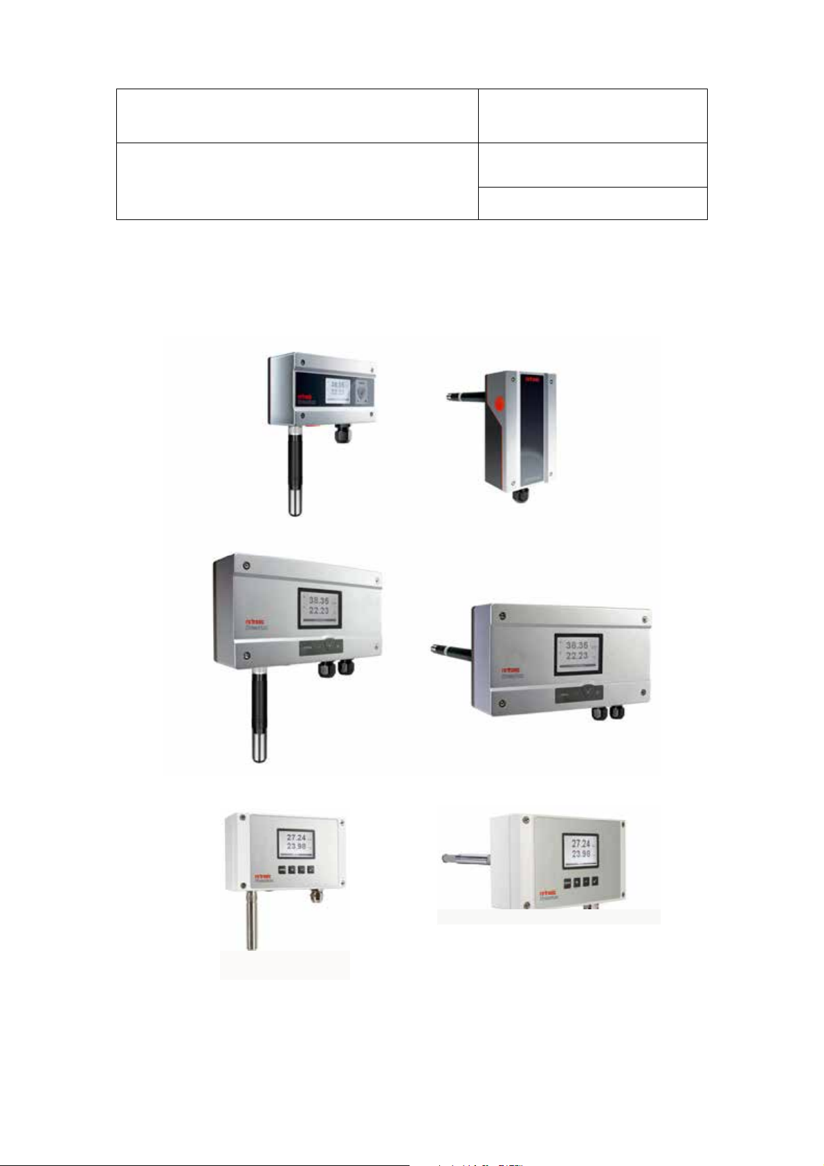
Depending on the supply voltage, the HF5 uses three different sizes of enclosure
2.1 Supply voltage up to 40 VDC / 28 VAC (ABS housing)
Vertical mounting applies only to:
• HF52 type D without keypad and display
• HF53 and HF54 type D without keypad and
display or without digital option
All other models are mounted horizontally
Probe
connector
Instruction Manual
Document Type
4 of 37
Probe
connector
© 2009-2016; Rotronic AG E-M-HF5-V3_6
Find Quality Products Online at: sales@GlobalTestSupply.com
www.GlobalTestSupply.com
E-M-HF5-V3_6
Type D: duct mount
Type W: wall mount
Document code Unit
Rotronic AG
Bassersdorf, Switzerland
HygroFlex HF5 Humidity Temperature
Transmitters: User Guide
Document title
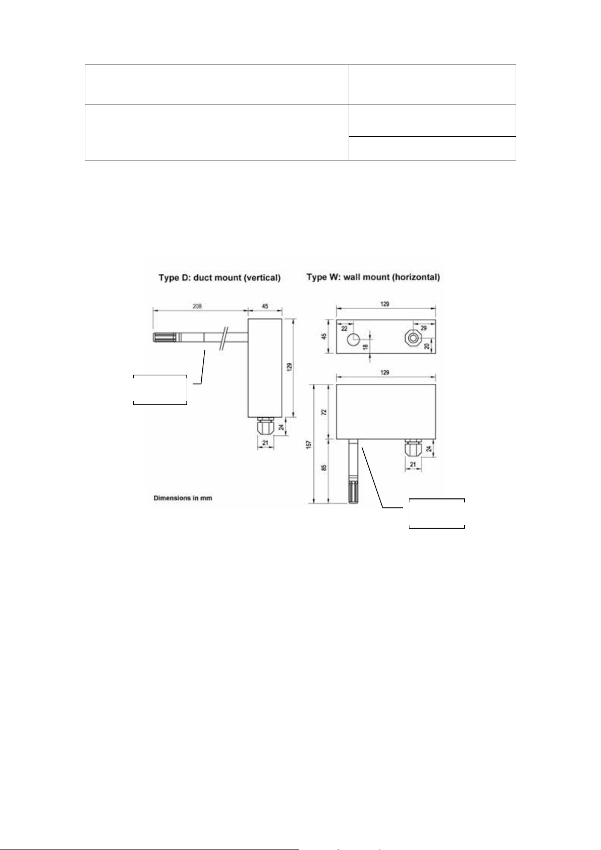
2.2 Supply voltage up to 40 VDC / 28 VAC (Alu housing)
Probe
connector
Probe
connector
Instruction Manual
Page
5 of 37
Document Type
2.3 Supply voltage 100…240 VAC (ABS housing)
Probe
connector
Probe
connector
© 2009-2016; Rotronic AG E-M-HF5-V3_6
Find Quality Products Online at: sales@GlobalTestSupply.com
www.GlobalTestSupply.com

E-M-HF5-V3_6
Document code Unit
Rotronic AG
Bassersdorf, Switzerland
HygroFlex HF5 Humidity Temperature
Transmitters: User Guide
Document title
Instruction Manual
Page
6 of 37
Document Type
2.4 Models with USB or Ethernet interface
USB or Ethernet interface
3 General description
It is important to comply with the manufacturer its instructions. If these instructions are not complied with, the
afety characteristics of the HF5-device can be influenced.
s
3.1 Power supply options
Depending on the circuit type, the HF5 requires the following power supply:
a) HF52 (2-wire loop powered, analog outputs): 10…28 VDC - depending on the load connected to the
output(s). The minimum supply voltage can be determined as follows:
V min = 10 V + (0.02 x Load*) *Load resistance in Ω.
For the maximum load of 500 Ω, the minimum supply voltage is 10 + (0.02 x 500) = 20 VDC. With both
output circuits closed, the maximum current consumption is 40 mA.
b) HF53, HF54 and HF56 (3-wire, analog outputs optionally combined with a digital output):
- HF531/532/535: 18…40 VDC / 13…28 VAC
- HF533: 6…40 VDC / 13…28 VAC
- HF534: 10…40 VDC / 12…28 VAC
- HF54: 9…36 VDC / 7…24 VAC, galvanic isolation of the analog outputs and power supply
- HF56: 100…240 VAC, galvanic isolation of the analog outputs and power supply
HF53 and HF54: with both output circuits closed, the typical current consumption is 100 mA.
HF56: typical current consumption <50 mA at 100 VAC and <35 mA at 240 VAC
Please verify the product identification label to determine which power supply option is installed on your
transmitter.
c) HF556, HF557 and HF566 (digital output only):
- HF556: 5…40 VDC / 12…28 VAC
- HF557: PoE (power over Ethernet).The HF557 is not available with a RS-485 interface and can be
powered only via a LAN.
- HF566: 100…240 VAC
Typical current consumption
© 2009-2016; Rotronic AG E-M-HF5-V3_6
Find Quality Products Online at: sales@GlobalTestSupply.com
www.GlobalTestSupply.com

E-M-HF5-V3_6
Document code Unit
Rotronic AG
Bassersdorf, Switzerland
HygroFlex HF5 Humidity Temperature
Transmitters: User Guide
Document title
Instruction Manual
Page
7 of 37
Document Type
HF556 with USB interface : 100 mA
HF556 with Ethernet (TCP/IP) interface and HF557 : 300 mA
HF566 with Ethernet (TCP/IP) interface : <50 mA at 100 VAC and <35 mA at 240 VAC
3.2 Measured parameters
A HygroClip 2 from Rotronic has to be used with the HF5 transmitter.
he HygroClip 2 probe together with the HF5 transmitter measures relative humidity with a ROTRONIC
T
Hygromer® IN1 capacitive sensor and temperature with a Pt100 RTD.
3.3 Calculated parameters
Using the ROTRONIC HW4 software, the HF5 can be configured by the user to calculate one of the following
parameters:
o Dew point (Dp) above and below freezing
o Frost point (Fp) below freezing and dew point above freezing
o Wet bulb temperature (Tw)
o Enthalpy (H)
o Vapor concentration (Dv)
o Specific humidity (Q)
o Mixing ratio by weight (R)
o Vapor concentration at saturation (Dvs)
o Vapor partial pressure (E)
o Vapor saturation pressure (Ew)
Note: some of the above parameters depend on the value of the barometric pressure. Using the ROTRONIC
HW4 software, a fixed barometric pressure value can be specified. For instructions see the following HW4
manual: E-M-HW4v3-F2-005
3.4 Analog output signals
Parameter:
ith the ROTRONIC HW4 software any of the two analog output signals can be made to correspond to one of
W
the following:
• Relative humidity
• Temperature
• Calculated parameter
Any output can also be disabled.
Output Scale:
The scale of each analog output can be set within the numerical limits of -999.99 and 9999.99. The D/A
converters used to generate the analog output signals feature a 16-bit resolution.
Signal Type:
Both analog outputs provide the same type of signal. With the exception of the HF52 (always 4…20 mA), the
type of signal can be selected with the ROTRONIC HW4 software to any of the following:
Current output: 0…20 mA, 4…20 mA (up to 15 V)
Voltage output: 0…1V, 0…5V or 0…10V (see 4.3).
© 2009-2016; Rotronic AG E-M-HF5-V3_6
Find Quality Products Online at: sales@GlobalTestSupply.com
www.GlobalTestSupply.com

E-M-HF5-V3_6
Document code Unit
Rotronic AG
Bassersdorf, Switzerland
HygroFlex HF5 Humidity Temperature
Transmitters: User Guide
Document title
Instruction Manual
Page
8 of 37
Document Type
3.5 Digital outputs
Models with a digital output can simultaneously transmit 3 parameters: relative humidity, temperature and
calculated parameter
) RS-485 serial interface
a
Some models of the HF5 are equipped with a RS-485 serial interface. This can be used to connect together
up to 64 devices in a multi-dropped arrangement. In principle, an unlimited number of such networks can be
monitored with the HW4 software, but each RS-485 multi-drop network is limited to 64 devices. The HF5 can
be used either as a slave or a master, without special configuration. The master is automatically the device
that is directly connected to a PC by means of a USB port or Ethernet (TCP/IP) port.
RS-485 Compatibility: The communication protocol used by the HF5 and other AirChip 3000 products is not
compatible with the protocol used by the previous generation of ROTRONIC instruments. Do not connect
legacy products and AirChip 3000 products to the same RS-485 multi-drop network.
b) USB or Ethernet interface
Some models of the HF5 are available with a USB or Ethernet client interface in addition to the RS-485
interface. In this case the protection grade of the HF5 enclosure is no longer IP65 / NEMA 4 rated.
3.6 Service connector
The client service connector is a UART digital interface (Universal Asynchronous Receiver Transmitter) with a
mini-USB type connector. This allows connecting the HF5 with a service cable to a PC running the
ROTRONIC HW4 software. See “Maintenance” for the location of the service connector and for the type of
service cable to be used. The service connector is used to configure the HF5 and to and update its firmware
with the HW4 software.
Note: any digital output (USB, Ethernet and RS-485) offers the same functionality as the service connector.
3.7 Probe
The HF5 is compatible with all available models of HygroClip 2 probes. For detailed information on the probes
ee document E-M-HC2 Probes-V1.
s
3.8 HW4 software version compatibility
The HF5 version 2 requires HW4 version 3.0.0 or higher for full functionality of the Device Manager function.
4 User configurable settings and functions
The HF5 ships configured as specified on the customer order. Models with analog outputs only can be
installed and used just as any conventional humidity and temperature transmitter and most users will never
need to use the HF5 configurable settings and functions. Models with a digital output generally require some
configuration by the user.
Making use of the HF5 and probe configurable settings and functions is entirely up to the user and the
appropriate settings depend on the user application. We have provided below a short description of the HF5
and probe functions and also indicated the factory default settings.
© 2009-2016; Rotronic AG E-M-HF5-V3_6
Find Quality Products Online at: sales@GlobalTestSupply.com
www.GlobalTestSupply.com

E-M-HF5-V3_6
AirChip 3000 Functions
Description
o
Functions
Description
enabled or disabled
Functions
Description
Document code Unit
Rotronic AG
Bassersdorf, Switzerland
HygroFlex HF5 Humidity Temperature
Transmitters: User Guide
Document title
Instruction Manual
Page
9 of 37
Document Type
4.1 Function overview
MEASUREMENT ACCURACY AND RELIABILITY (PROBE FUNCTIONS)
► Humidity / temperature adjustment o 1-point or multi-point humidity calibration or adjustment
o 1-point or 2-point temperature calibration or adjustment
o Generate a time stamp for calibrations and adjustments
o Retain and view last adjustment date and adjustment values
Generate calibration and adjustment protocols
► Automatic humidity sensor test
and optional drift compensation
► Data recording The data recording function differs from a true data logging
MEASUREMENT LOOP VALIDATION
Tests the humidity sensor for drift caused by contaminants and
can be used to automatically apply a correction. The test is
automatically carried out at regular intervals of time. Can be
configured, enabled, or disabled
The humidity sensor status can be verified either with the HW4
software or with the instrument display (if available) and is
shown as Good, SQ-tuned (corrected for drift) or Bad (defective)
Not available when the probe is connected to a HF52
function in the sense that the AirChip 3000 does not time stamp
the data. The data recording function can be used to investigate
events such as a sensor malfunction as well as to retrieve data
that would otherwise be lost
o Start or stop data recording - up to 2000 value pairs (%RH
and temperature). Starting a recording session erases all
previously recorded data
o The recording mode and log interval can be specified
o When the device is powered off, the recording session is
paused but not ended As long as the recording session has
not been ended, the device automatically resumes recording
data when powered up again
o The recorded data can be downloaded to a PC with the
HW4 software, time stamped and viewed
Not available when the probe is connected to a HF52
► Simulator mode Used to make the HF5 generate fixed values for the humidity,
temperature and calculated parameter. Can be configured,
DEVICE SAFEGUARDS
► Device write protection Used to protect the HF5 with a password to prevent
unauthorized digital access by a digital user. Can be configured,
enabled or disabled
► Internal menu access from keypad Used to prevent accidental changes to the HF5 settings and
© 2009-2016; Rotronic AG E-M-HF5-V3_6
Find Quality Products Online at: sales@GlobalTestSupply.com
www.GlobalTestSupply.com
temperature-humidity adjustment by disabling the MENU key on
the optional keypad. Can be enabled or disabled
E-M-HF5-V3_6
AirChip 3000 Functions
Description
seen on the optional display
Can be configured, enabled or disabled
X X
X X
Document code Unit
Rotronic AG
Bassersdorf, Switzerland
HygroFlex HF5 Humidity Temperature
Transmitters: User Guide
Document title
Instruction Manual
Page
10 of 37
Document Type
PROCESS PROTECTION AND PROTECTION OF OTHER DEVICES
► Limit humidity output to 100 %RH This probe function is used to prevent the humidity signal from
exceeding 100 %RH when condensation forms on the sensor.
Can be enabled or disabled
► Out-of-limit value alarm Used to specify the normal range for humidity, temperature and
the calculated parameter depending on the user application.
Can be configured, enabled or disabled
Out-of-limit values trigger a digital alarm which can be also be
► Bad sensor alarm This is a built-in probe function. Cannot be disabled
► Fail safe mode Used to specify a "safe" fixed value for humidity and for
A bad humidity or temperature sensor triggers a digital alarm
which can be also be seen on the optional HF5 display provided
that the HF5 is set to monitor probe alarms
temperature (HF5 or probe) in the event of:
o Loss of communication with the probe (HF5 function)
o Sensor failure (probe function)
4.2 Interaction between the HF5 and probe functions
It is important to note that when used together, the HF5 transmitter and HC2 probe (HygroClip 2) constitute a
2-component system. Each system component has its own microprocessor, firmware and functions. Some of
these functions are unique to each system component. Other functions are found in both components.
HF52 (2-wire, loop powered transmitter): due to the necessity of limiting the current consumption of the
combination of HF52 and HC2 probe to less than 4 mA, several probe functions such as RH sensor test, data
recording and probe adjustment are not available with the HF52.
The functions and settings of the HF5 transmitter and HygroClip 2 probe (HC2) operate together as indicated
below:
Function / Setting HF5 HC2 Notes
Device protection
RS-485 address
Device Name
Calculation
Data refresh rate
Simulator function
X X
X X
X
X X
Individual to the HF5 and HC2 probe
Individual to the HF5 and HC2 probe
User defined description
The device name of the HC2 probe is not displayed by HW4 and is
replaced with the HF5 Input Name
Psychrometric calculation
HF5 setting overrides HC2 probe setting
Depending on the model, the data refresh rate is as follows:
HF52: typically 20 s
Other models: typically 1 s
Generates fixed humidity and / or temperature value
When enabled, the HF5 settings override the HC2 probe settings
© 2009-2016; Rotronic AG E-M-HF5-V3_6
Find Quality Products Online at: sales@GlobalTestSupply.com
www.GlobalTestSupply.com
E-M-HF5-V3_6
monitor probe alarms).
Document code Unit
Rotronic AG
Bassersdorf, Switzerland
HygroFlex HF5 Humidity Temperature
Transmitters: User Guide
Document title
Instruction Manual
Page
11 of 37
Document Type
Function / Setting HF5 HC2 Notes
The HF5 setting overrides HC2 probe setting regarding the HF5
signals. The HC2 probe settings still apply when the probe is used
Unit system
Out-of-limits value alarm
Analog outputs
X X
X X
X X
alone
Make sure to use the same humidity symbol and the same
temperature unit for both the HF5 and probe.
The HF5 settings are independent from the HC2 probe settings.
The HC2 probe settings have an effect only when the HF5 is
enabled to monitor alarms generated by the probe
When out-of-limit values have been defined for the same parameter
for both the HF5 and probe, any alarm is triggered based on the
narrowest set of limits (assuming that the HF5 has been set to
Parameter and scale
The HC2 probe settings have no effect on the HF5
4.3 Analog output signal type (except HF52)
Both analog outputs of the HF5 provide the same type of signal. With the exception of the HF52 (always
4…20 mA), the type of signal can be selected with the ROTRONIC HW4 software to any of the following:
0…20 mA, 4…20 mA, 0…1V, 0…5V or 0…10V. To select the analog signal type proceed as follows:
• Use the appropriate model of service cable (see Maintenance > Service Cable) to connect the
service connector of the HF5 to a USB port of a PC with the HW4 software installed (HW4 3.0.0 or
higher). Note that the ROTRONIC USB driver must be installed on the PC as explained in the HW4
manual E-M-HW4v3-Main
• Start HW4 on the PC and search for the HF5 (HW4 Main Menu Bar > Devices and Groups > Search
for USB Masters).
• After finding the HF5 with HW4, expand the device tree to see the HF5 functions. Select Device
Manager.
• For further instructions see HW4 manual E-M-HW4v3-F2-005
No adjustment is required after changing the type of output signal.
5 Mechanical installation
5.1 General guidelines
Relative humidity is extremely dependent on temperature. Proper measurement of relative humidity requires
hat the probe and its sensors be at exactly the temperature of the environment to be measured. Because of
t
this, the location where you choose to install the probe can have a significant effect on the performance of the
instrument. The following guidelines should guarantee good instrument performance:
a) Select a representative location: install the probe where humidity, temperature and pressure
© 2009-2016; Rotronic AG E-M-HF5-V3_6
Find Quality Products Online at: sales@GlobalTestSupply.com
conditions are representative of the environment to be measured.
b) Provide good air movement at the probe: air velocity of at least 200 ft/ minute (1 meter/second)
facilitates adaptation of the probe to changing temperature.
c) Avoid the following: (1) Close proximity of the probe to a heating element, a cooling coil, a cold or
hot wall, direct exposure to sun rays, etc. (2) Close proximity of the probe to a steam injector,
www.GlobalTestSupply.com
E-M-HF5-V3_6
Vertical
:
digital
option
Horizonta
l:
HF53, HF54 type D with
Document code Unit
Rotronic AG
Bassersdorf, Switzerland
HygroFlex HF5 Humidity Temperature
Transmitters: User Guide
Document title
Instruction Manual
Page
12 of 37
Document Type
humidifier, direct exposure to precipitation, etc. (3) Unstable pressure conditions resulting from
excessive air turbulence.
d) Immerse as much of the probe as possible in the environment to be measured.
e) Prevent the accumulation of condensation water at the level of the sensor leads. Install the
probe so that the probe tip is looking downward. If this is not possible, install the probe horizontally.
5.2 HF5 enclosure
The HF5 enclosure consists of a base and a cover held together with 4 screws. To open the enclosure, use a
etric 2.5 mm or 3 mm hex key. Prior to re-assembling the enclosure, verify that the red seal is sitting properly
m
in its groove on the base.Installation of the HF5 type D (through wall mount)
Mounting position of the enclosure
• HF52 type D without
keypad and display
• HF53 and HF54 type D
without keypad and
display, and without
• HF52 type D with
keypad and display
•
keypad and display or
with digital option
• All other type D models
Mounting hardware
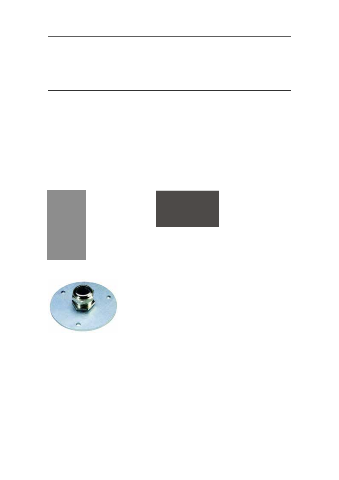
he QMA-15 consists of a flange and compression fitting and is designed to hold the probe of the HF5 type D
T
when mounted through a wall (see Accessories). The HF5 does not require any additional support.
© 2009-2016; Rotronic AG E-M-HF5-V3_6
Find Quality Products Online at: sales@GlobalTestSupply.com
www.GlobalTestSupply.com

E-M-HF5-V3_6
Horizontal:
Document code Unit
Rotronic AG
Bassersdorf, Switzerland
HygroFlex HF5 Humidity Temperature
Transmitters: User Guide
Document title
5.3 Installation of the HF5 type W (surface mount)
Mounting position of the enclosure
HF52, HF53, HF54, HF55 and HF56 type W
Mounting hardware
Instruction Manual
Page
13 of 37
Document Type
ethod 1: The HF5 is supplied with 2 screws, 2 drywall anchors and two rubber washers. The base of the
M
enclosure has 2 screw-wells (see drawing) that are normally closed at the bottom. Use the template provided
with the HF5 to drill mounting holes in the wall and insert the drywall anchors. Place a rubber washer on each
screw. Insert a screw in each well and push to open the bottom of the well.
Method 2: When a DIN-rail (35 mm / 1 3/8 “) is available use part AC5002 (not included). This is a DIN-rail
mounting kit consisting of 2 clamps that attach to the back of the enclosure with the screws provided.
6 Electrical installation
The safety of the installed system, where the device is integrated, is the responsibility of the builder of the
ystem.
s
6.1 General wiring guidelines
Power supply wiring
Heavy machinery and instrumentation should not share the same power supply wiring. If this cannot be
avoided, noise filters and surge protectors should be used. Most UPS devices have those features already
integrated.
Electrical Safety Warning (HF56x)
The HF5 transmitter series includes models designed to operate with a supply voltage of 100…240 VAC. For
safety reasons, the electrical installation of these models must be designed providing an adequate protection.
A form of an external circuit breaker, switch, fuse or other can be used to separate the transmitter from the
supply voltage. Appropriate safety warnings and instructions must be located by the transmitter in order to
prevent electrical shock with open transmitter enclosure.
© 2009-2016; Rotronic AG E-M-HF5-V3_6
Find Quality Products Online at: sales@GlobalTestSupply.com
www.GlobalTestSupply.com

E-M-HF5-V3_6
Document code Unit
Rotronic AG
Bassersdorf, Switzerland
HygroFlex HF5 Humidity Temperature
Transmitters: User Guide
Document title
Instruction Manual
Page
14 of 37
Document Type
The guarantee of the security of the whole system which includes the HF5 is the responsibility of the
developer of the system.
Ensure that the cable gland is tightened so that this is not detachable by hand.
The electrical installation of the device must be performed by a qualified electrician and correspond with IEC
(International Electrotechnical Commission) requirements.
It is important to ensure, to use a suitable mains cable:
- Voltage Range min. 240 VAC
- Cable cross-section : 6 ... 8 mm
- Max Wire cross : 2.5 mm2
- Recommended : 3x075mm
- Specify torque: 3-5 Nm
2
H05VV-F Cable
General guidelines for signal cables
The following guidelines are derived from International Standard IEC 61158 / IEC 61784 for the transmission
of signals by copper wires. When planning an installation, the rules provided by IEC 61158 / IEC 61784should
be followed under consideration of local circumstances to determine the position of machines and equipment.
Whenever the level of electromagnetic interference is expected to be high, both the instruments and signal
cables should be placed as far away as possible from the source of interference.
In general, signal cables should be installed in bundles or channels / conduits, separate from other cables as
indicated in the table below:
• Bus signals such as RS485
• Data signals for PCs, printers etc.
• shielded analog inputs
• unshielded direct current (<= 60V)
• shielded process signals (<= 25 V)
• unshielded alternate current (<= 25V)
• coaxial cables for CRT monitors
• direct current from 60 V to 400 V
(unshielded)
• alternate current from 25V to 400 V
(unshielded)
• direct and alternate current > 400 V
(unshielded)
• Telephone lines
• lines leading into EX-rated areas
© 2009-2016; Rotronic AG E-M-HF5-V3_6
Find Quality Products Online at: sales@GlobalTestSupply.com
www.GlobalTestSupply.com
in common bundles or channels / conduits
in separated bundles or channels /
conduits, without minimum distance /
in separated bundles or channels /
conduits, without minimum distance

E-M-HF5-V3_6
Document code Unit
Rotronic AG
Bassersdorf, Switzerland
HygroFlex HF5 Humidity Temperature
Transmitters: User Guide
Document title
Instruction Manual
Page
15 of 37
Document Type
Lightning protection
Cabling in areas with a risk of lightning requires a lightning protection. For cabling underground in between
buildings, we recommend the use of special fiber optic cables. If this is not possible, use copper cables that
are suitable for underground installation.
6.2 Guidelines for RS-485 wiring
See document
E-DV04-RS485.01: RS485 Network Installation and Start-up Guidelines
6.3 Cable grip and cable specifications
Depending on the model, the HF5 is supplied either with one or two M16 sealing cable grips or with one or two
½” conduit adapters. The M16 cable grip provides effective sealing only with cables having the proper outside
diameter. Preferably, use a cable with an outside diameter of 6 to 8 mm (0.236 to 0.314 inch) with 18 AWG
wires.
© 2009-2016; Rotronic AG E-M-HF5-V3_6
Find Quality Products Online at: sales@GlobalTestSupply.com
www.GlobalTestSupply.com
E-M-HF5-V3_6
Terminals
Description
Terminals
Description
OUT-1
Document code Unit
Rotronic AG
Bassersdorf, Switzerland
HygroFlex HF5 Humidity Temperature
Transmitters: User Guide
Document title
6.4 Wiring
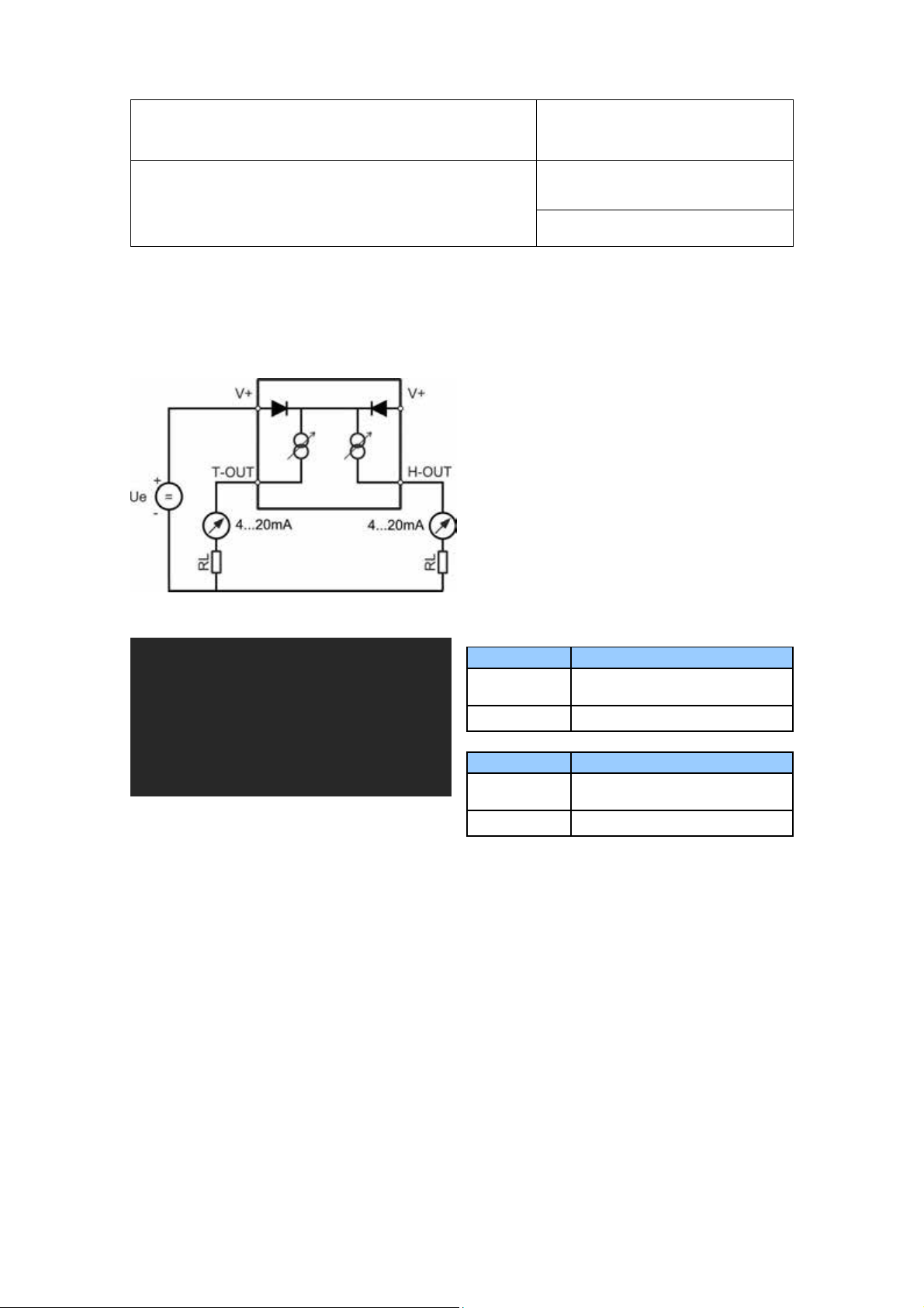
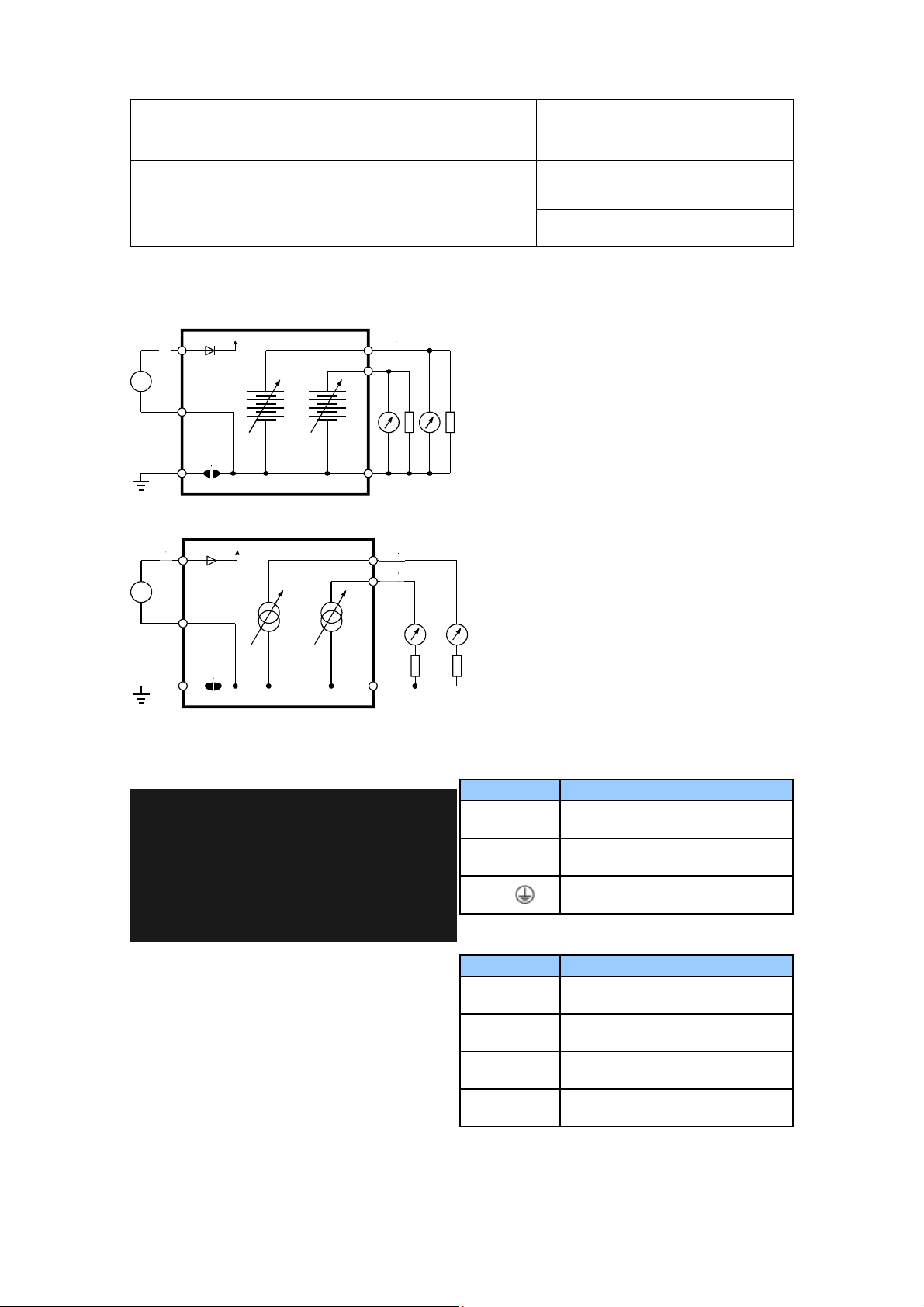
HF52: 2-wire, loop powered transmitter
lectrical diagram
E
Terminal block diagram
Instruction Manual
Document Type
Page
16 of 37
The maximum permissible cable length connecting the
HF52 to other devices is determined by the total
resistance resulting from the addition of the cable
resistance and that of the devices connected in series
with the unit.
This resistance should not exceed 500 Ω.
K2-2: T-OUT
K2-1: V+ Power supply: 10…28 VDC (+)
K1-2: H-OUT
Note: connect the + of the power supply to only one of the V+ terminals. The two terminals marked V+ are
internally connected.
K1-1: V+ Power supply: 10…28 VDC (+)
Temperature output (+)
OUT-2
Relative humidity or dew point (+)
Measuring humidity or temperature only
peration of the HF52 does not require both current loops to be closed. When using the HF52 to measure
O
either humidity only or temperature only, close only the loop that is being used.
Using the ROTRONIC HW4 software, any unused output of the HF52 can be disabled.
© 2009-2016; Rotronic AG E-M-HF5-V3_6
Find Quality Products Online at: sales@GlobalTestSupply.com
www.GlobalTestSupply.com
E-M-HF5-V3_6
Terminals
Description
Terminals
Description
V +
OUT 2
1
B
2
U
B
B 2
U
OUT 1
GND
Document code Unit
Rotronic AG
Bassersdorf, Switzerland
HygroFlex HF5 Humidity Temperature
Transmitters: User Guide
Document title
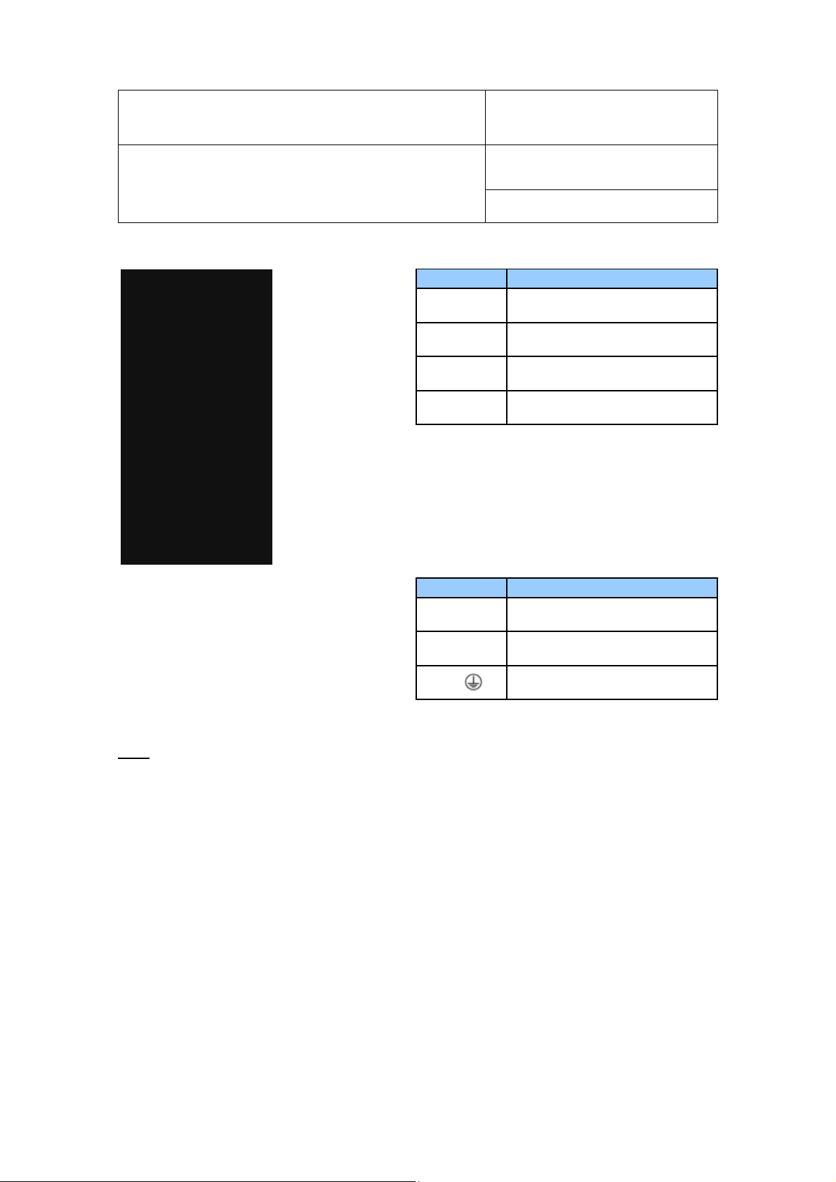
HF53: 3-wire transmitter
Electrical diagram for voltage outputs
OUT
GND
Electrical diagram for current outputs
V +
OUT 2
B
Terminal block diagram (analog outputs only)
Type D and W (horizontal mount)
Instruction Manual
Document Type
17
Page
of 37
The maximum permissible cable length can be
determined under consideration of the voltage drop
caused by the current flowing to the devices connected
to the unit. The voltage drop in the cable depends both
on cable resistance and on the equivalent resistance
of the devices connected in parallel to the unit. The
total resistance connected to each unit output should
be at least 1000 Ω. Cable resistance should not be
more than 1/1000 of the load resistance.
The maximum permissible cable length, connecting
the unit to other devices, is determined by the total
resistance resulting from the addition of the cable
resistance and that of the devices connected in
series with the unit.
This resistance should not exceed 500 Ω.
K1-1: V- Power supply (-) or neutral
K1-2: V+
K1-3:
Power supply: 18…40 VDC (+)
or 12…28 VAC (Phase)
Protective ground (see note below)
K2-4: GND Ground (tied with other GND)
K2-3: GND Ground (tied with other GND)
K2-2: OUT2
K2-1: OUT1 Relative humidity or dew point (+)
© 2009-2016; Rotronic AG E-M-HF5-V3_6
Find Quality Products Online at: sales@GlobalTestSupply.com
www.GlobalTestSupply.com
Temperature output (+)
E-M-HF5-V3_6
Terminals
Description
Terminals
Description
Document code Unit
Rotronic AG
Bassersdorf, Switzerland
HygroFlex HF5 Humidity Temperature
Transmitters: User Guide
Document title
Type D (vertical mount)
Instruction Manual
Document Type
Page
K2-4: GND Ground (tied with other GND)
K2-3: GND Ground (tied with other GND)
K2-2: OUT2 Temperature output (+)
K2-1: OUT1 Relative humidity or dew point (+)
18 of 37
K6-1: V- Power supply (-) or neutral
K6-2: V+
K6-3:
Power supply: 18…40 VDC (+)
or 12…28 VAC (Phase)
Protective ground (see note below)
Note: Terminals K1-3 or K6-3 (protective or earth ground) are tied with GND. If this is not wanted, a land
(B18) on the PCB must be removed.
© 2009-2016; Rotronic AG E-M-HF5-V3_6
Find Quality Products Online at: sales@GlobalTestSupply.com
www.GlobalTestSupply.com

E-M-HF5-V3_6
Terminals
Description
Terminals
Description
Terminals
Description
Document code Unit
Rotronic AG
Bassersdorf, Switzerland
HygroFlex HF5 Humidity Temperature
Transmitters: User Guide
Document title
Instruction Manual
Page
19 of 37
Document Type
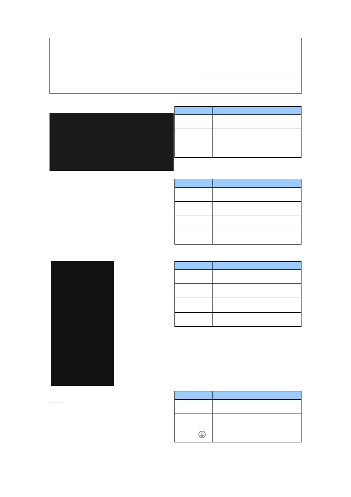
Terminal block diagram (analog outputs and digital option)
Type D and W (horizontal mount)
K1-1: V- Power supply (-) or neutral
K1-2: V+
K1-3:
K2-4: GND Ground (tied with other GND)
K2-3: GND Ground (tied with other GND)
K2-2: OUT2 Temperature output (+)
K2-1: OUT1 Relative humidity or dew point (+)
Power supply: 18…40 VDC (+)
or 12…28 VAC (Phase)
Protective ground (see note below)
K3-4: D-
K3-3: D+
K3-2: GND Ground / Power supply (-)
K3-1: PWR
Notes:
Terminal K1-3: this terminal (protective or earth ground) is tied with GND. If this is not wanted, a land (B18)
on the PCB must be removed.
Terminal block K3 (RS-485): terminals K3-1 and K3-2 can be used to power the HF53 from a 15 to 24 VDC
power supply connected to the RS-485 main data line. In this case, do not use terminals K1-1 and pin K1-2
(normally used to power the HF53).
USB or TCP/IP port: this port is optional
Measuring humidity or temperature only
Operation of the HF53 does not require both current loops to be closed. When using the HF53 to measure
either humidity only or temperature only, close only the loop that is being used.
Using the ROTRONIC HW4 software, any unused output of the HF53 can be disabled.
RS-485 Bi-directional
TX- / RX -
RS-485 Bi-directional
TX+ / RX +
DC (+) 15…24 VDC (+)
(optional, see note below)
© 2009-2016; Rotronic AG E-M-HF5-V3_6
Find Quality Products Online at: sales@GlobalTestSupply.com
www.GlobalTestSupply.com

E-M-HF5-V3_6
Document code Unit
Rotronic AG
Bassersdorf, Switzerland
HygroFlex HF5 Humidity Temperature
Transmitters: User Guide
Document title
HF54: 3-wire transmitter, galvanic isolation of the analog outputs
Electrical diagram for voltage outputs
V+
DC
U
B
GND
DC
Electrical diagram for current outputs
V+
DC
U
B
GND
DC
Terminal block diagram (analog outputs only)
OUT1
OUT2
GND
OUT1
OUT2
GND
The maximum permissible cable length
can be determined under consideration
of the voltage drop caused by the current
flowing to the devices connected to the
unit. The voltage drop in the cable
depends both on cable resistance and on
the equivalent resistance of the devices
connected in parallel to the unit. The total
resistance connected to each unit output
should be at least 1000 Ω. Cable
resistance should not be more than
1/1000 of the load resistance.
The maximum permissible cable length,
connecting the unit to other devices, is
determined by the total resistance
resulting from the addition of the cable
resistance and that of the devices
connected in series with the unit. This
resistance should not exceed 500 Ω.
Page
Instruction Manual
Document Type
20 of 37
© 2009-2016; Rotronic AG E-M-HF5-V3_6
Find Quality Products Online at: sales@GlobalTestSupply.com
www.GlobalTestSupply.com
E-M-HF5-V3_6
Terminals
Description
Terminals
Description
Terminals
Description
Terminals
Description
Document code Unit
Rotronic AG
Bassersdorf, Switzerland
HygroFlex HF5 Humidity Temperature
Transmitters: User Guide
Document title
Type D and W (horizontal mount)
Type D (vertical mount)
Instruction Manual
Document Type
Page
K1-1: V- Power supply (-) or neutral
K1-2: V+
K1-3: Protective ground (see note below)
K2-4: GND Ground (tied with other GND)
K2-3: GND Ground (tied with other GND)
K2-2: OUT2 Temperature output (+)
K2-1: OUT1 Relative humidity or dew point (+)
Power supply: 18…40 VDC (+)
or 12…28 VAC (Phase)
21 of 37
Note: Terminals K1-3 or K6-3 (protective or earth
ground) are tied with GND. If this is not wanted, a
land (B18) on the PCB must be removed.
K2-4: GND Ground (tied with other GND)
K2-3: GND Ground (tied with other GND)
K2-2: OUT2 Temperature output (+)
K2-1: OUT1 Relative humidity or dew point (+)
K6-1: V- Power supply (-) or neutral
K6-2: V+
K6-3:
Power supply: 18…40 VDC (+)
or 12…28 VAC (Phase)
Protective ground (see note below)
© 2009-2016; Rotronic AG E-M-HF5-V3_6
Find Quality Products Online at: sales@GlobalTestSupply.com
www.GlobalTestSupply.com

E-M-HF5-V3_6
Terminals
Description
Terminals
Description
Terminals
Description
Document code Unit
Rotronic AG
Bassersdorf, Switzerland
HygroFlex HF5 Humidity Temperature
Transmitters: User Guide
Document title
Instruction Manual
Page
22 of 37
Document Type
Terminal block diagram (analog outputs and digital option)
Type D and W (horizontal mount)
K1-1: V- Power supply (-) or neutral
K1-2: V+
K1-3:
K2-4: GND Ground (tied with other GND)
K2-3: GND Ground (tied with other GND)
K2-2: OUT2 Temperature output (+)
K2-1: OUT1 Relative humidity or dew point (+)
Power supply: 18…40 VDC (+)
or 12…28 VAC (Phase)
Protective ground (see note below)
K3-4: D-
K3-3: D+
K3-2: GND Ground
K3-1: PWR Not used
RS-485 Bi-directional
TX- / RX -
RS-485 Bi-directional
TX+ / RX +
Notes:
Terminal K1-3: this terminal (protective or earth ground) is tied with GND. If this is not wanted, a land (B18)
on the PCB must be removed.
USB or TCP/IP port: this port is optional
Measuring humidity or temperature only
Operation of the HF54 does not require both current loops to be closed. When using the HF54 to measure
either humidity only or temperature only, close only the loop that is being used.
Using the ROTRONIC HW4 software, any unused output of the HF54 can be disabled.
© 2009-2016; Rotronic AG E-M-HF5-V3_6
Find Quality Products Online at: sales@GlobalTestSupply.com
www.GlobalTestSupply.com

E-M-HF5-V3_6
Terminals
Description
Terminals
Description
Document code Unit
Rotronic AG
Bassersdorf, Switzerland
HygroFlex HF5 Humidity Temperature
Transmitters: User Guide
Document title
Instruction Manual
Page
23 of 37
Document Type
HF556: digital output
Connectors and terminal block diagram
Notes:
Terminal K1-3: this terminal (protective or earth ground) is tied with GND. If this is not wanted, a land (B18)
on the PCB must be removed.
Terminal block K3 (RS-485): terminals K3-1 and K3-2 can be used to power the HF55 from a 15 to 24 VDC
power supply connected to the RS-485 main data line. In this case, do not use terminals K1-1 and pin K1-2
(normally used to power the HF55).
WARNING: Connecting a device to an active Ethernet network can disrupt communications on the network.
Before connecting the HF5, make sure that it is properly configured for your network.
K1-1: V- Power supply (-) or neutral
K1-2: V+
K1-3:
K3-4: D-
K3-3: D+
K3-2: GND
K3-1: PWR
Power supply: 5…40 VDC (+)
or 12…28 VAC (Phase)
Protective ground (see note
below)
RS-485 Bi-directional
TX- / RX -
RS-485 Bi-directional
TX+ / RX +
Ground / Power supply (-)
(tied with other GND)
DC (+) 15…24 VDC (+)
(optional, see note below)
© 2009-2016; Rotronic AG E-M-HF5-V3_6
Find Quality Products Online at: sales@GlobalTestSupply.com
www.GlobalTestSupply.com

E-M-HF5-V3_6
DC
AC L
OUT2OUT1GND
Document code Unit
Rotronic AG
Bassersdorf, Switzerland
HygroFlex HF5 Humidity Temperature
Transmitters: User Guide
Document title
HF557: digital output, PoE (power over Ethernet)
This model is powered from the Ethernet LAN and has no terminal blocks.
WARNING:
Before connecting the HF5, make sure that it is properly configured for your network.
Connecting a device to an active Ethernet network can disrupt communications on the network.
Page
Instruction Manual
Document Type
24
of 37
HF56: 100…240 VAC supply voltage
Electrical diagram for voltage outputs
The maximum permissible cable length can be determined under consideration of the voltage drop on the
cable.
The voltage drop in the cable depends both on cable resistance and on the equivalent resistance of the
devices connected in parallel to the unit.
The total resistance connected to each unit output has to be at least 1000 Ω.
Cable resistance should not be more than 1/1000 of the load resistance.
~
AC N
AC
© 2009-2016; Rotronic AG E-M-HF5-V3_6
Find Quality Products Online at: sales@GlobalTestSupply.com
www.GlobalTestSupply.com

E-M-HF5-V3_6
AC
DC
AC L
GND
Document code Unit
Rotronic AG
Bassersdorf, Switzerland
HygroFlex HF5 Humidity Temperature
Transmitters: User Guide
Document title
Instruction Manual
25
Page
of 37
Document Type
Electrical diagram for current outputs
The maximum permissible cable length, connecting the unit to other devices, is determined by the total
resistance (cable resistance + devices connected in series with the unit).
This resistance should not exceed 500 Ω.
Measuring humidity or temperature only
Operation of the HF56 does not require both current loops to be closed. When using the HF56 to measure
either humidity only or temperature only, close only the loop that is being used.
Using the ROTRONIC HW4 software, any unused output of the HF56 can be disabled.
~
AC N
OUT1
OUT2
© 2009-2016; Rotronic AG E-M-HF5-V3_6
Find Quality Products Online at: sales@GlobalTestSupply.com
www.GlobalTestSupply.com
E-M-HF5-V3_6
Terminals
Description
Terminals
Description
TCP / IP
Document code Unit
Rotronic AG
Bassersdorf, Switzerland
HygroFlex HF5 Humidity Temperature
Transmitters: User Guide
Document title
Terminal block diagram (analog outputs only)
AC N Power supply neutral: 100 to 240 VAC
AC L Power supply phase: 100 to 240 VAC
OUT1 Relative humidity or dew point
OUT2 Temperature output
Terminal block diagram (analog outputs and digital option)
GND Ground (tied with other GND)
GND Ground (tied with other GND)
AC N Power supply neutral: 100 to 240 VAC
Instruction Manual
Document Type
26
Page
of 37
AC L Power supply phase: 100 to 240 VAC
GND RS485 Ground
D+
D-
OUT1 Relative humidity or dew point
OUT2 Temperature output
GND Ground (tied with other GND)
GND Ground (tied with other GND)
RS485 Bi-directional TX+ / RX +
(< 10,5 V, <10mA)
RS485 Bi-directional TX- / RX –
(< 10,5 V, <10mA)
Grounding (all models)
We generally recommend grounding the (-) side of the power supply, especially if the electronics will be
subjected to a low humidity environment (35 %RH or less)
© 2009-2016; Rotronic AG E-M-HF5-V3_6
Find Quality Products Online at: sales@GlobalTestSupply.com
www.GlobalTestSupply.com

E-M-HF5-V3_6
Document code Unit
Rotronic AG
Bassersdorf, Switzerland
HygroFlex HF5 Humidity Temperature
Transmitters: User Guide
Document title
Instruction Manual
Page
27 of 37
Document Type
Operation
6.5 HF5 analog outputs
Use the HW4 software to configure the analog outputs of the HF5 as desired, complete the mechanical and
lectrical installation, connect the probe and simply power up the HF5.
e
6.6 HF5 digital outputs
The digital outputs of the HF5 use the standard RO-ASCII protocol and do not offer any other option. Users
who wish to read the measurement data without the HW4 software should consult ROTRONIC.
The different types of digital interface available with the HF5 are best used with a PC with the HW4 software
installed (version 3.0.0 or higher). In principle, users should be able to use communication software other than
HW4 to read measurement data from the HF5. In this case, communication is limited to the RDD (data
request) and REN (RS-485 address change) commands described separately in document E-M-AC3000-CP.
IMPORTANT: Depending on the type of digital interface, either the PC or the HF5 must be configured
by the user as indicated below.
a) USB connection
Prior to connecting the HF5 to a USB port you must install the ROTRONIC USB driver on the PC (available
from the HW4 CD or from www.rotronic-humidity.com). For instructions see the HW4 manual E-M-HW4v3-
Main (§ 7.3)
b) Ethernet (TCP/IP) connection
Prior to connecting the HF5 to an active Ethernet network you must configure the TCP/IP settings of the HF5
using either the HW4 software (version 2.1.0 or higher) or the TCP/IP configuration tool available from
www.rotronic-humidity.com. For instructions see the HW4 manual E-M-HW4v3-Main (§ 7.4) and technical
note IN-E-TCPIP-Conf
WARNING: Connecting a device to an active Ethernet network can disrupt communications on the network.
Before connecting the HF5, make sure that it is properly configured for your network
c) RS-485 serial interface (multi-drop)
Instructions for using the HF5 with a RS-485 network are provided in the following manuals:
E-M-HW4v3-Main (§ 7.5), E-M-HW4v3-F2-005 and E-DV04-RS485.01.
Notes:
o Instruments connected to the same RS-485 network must use the same baud rate and each instrument
must be given a unique RS-485 address (the address requirement applies to the HF5 but not to its probe)
o RS-485 Compatibility: The communications protocol used by the HF5 is the RO-ASCII protocol. This
protocol is not compatible with the protocol used by the previous generation of ROTRONIC products. Do
not connect legacy products and the HF5 to the same RS-485 multi-drop network.
The specifications of the RS-485 interface are as follows:
Baud rate : 19200
Parity : none
Data bits : 8
Stop bits : 1
© 2009-2016; Rotronic AG E-M-HF5-V3_6
Find Quality Products Online at: sales@GlobalTestSupply.com
www.GlobalTestSupply.com

E-M-HF5-V3_6
Main Menu
Menu Items
Selections / Information
Notes
Device Settings
Units
Metric / English
Contrast
LC display contrast adjustment
Trend
On / Off
Trend indication on the display
Device Information
Version
Serial Nbr
Address
Type
Name
Probe Information
Version
Serial Nbr
Address
Document code Unit
Rotronic AG
Bassersdorf, Switzerland
HygroFlex HF5 Humidity Temperature
Instruction Manual
Transmitters: User Guide
28
Document title
Page
of 37
6.7 Display and keypad option
Except for the HF52 (2-wire circuit type), the LC
display of the HF5 has a backlight.
The upper line corresponds to relative humidity the
bottom line corresponds to temperature.
If enabled the third line corresponds to the calculated
Parameter.
The display can be configured to show a trend indicator on each line:
▲: increasing value
▼: decreasing value
In the event of an alarm the display shows the symbol
For instructions about configuring the display, see the following HW4 manual:
[ ! ]
to the right of the value.
E-M-HW4v3-F2-005
6.8 Internal menu (optional keypad and display)
Note: Unauthorized access to the menu can be prevented by disabling the “display menu” setting
(use the HW4 software > Device Manager > Display)
Model HF52 (2-wire circuit type):
MENU key: open / close menu
ENTER key: menu item selection
Menu navigation keys + / Change value up / down
Document Type
.
Firmware version
Serial number
RS-485 address
Device type
Device name User defined
Firmware version
Serial number
RS-485 address
© 2009-2016; Rotronic AG E-M-HF5-V3_6
Find Quality Products Online at: sales@GlobalTestSupply.com
www.GlobalTestSupply.com

E-M-HF5-V3_6
Main Menu
Menu Items
Selections / Information
Notes
Name
Device name
User defined
Main
Menu
Menu Items
Selections / Information
Notes
Device Settings
Units
Metric / English
Back Light
Key Press / On / Off
Display backlight mode
Contrast
Trend
Device
Information
Version
Serial Nbr
Address
Type
Name
Probe Information
Version
Serial Nbr
Serial number
Address
RS-485 address
Name
Device name
User defined
SensorTest
Humidity sensor status
Off / Good / SQ
-
Tuned / Bad
Humidity Adjust
RefValue
<Acquire>
Save cal. point to probe memory
<Delete>
Erases all calibration points
Temperature Adjust
<Adjust>
Document code Unit
Rotronic AG
Bassersdorf, Switzerland
HygroFlex HF5 Humidity Temperature
Transmitters: User Guide
Document title
Other HF5 models:
LC display contrast adjustment
On / Off Trend indication on the display
Firmware version
Serial number
RS-485 address
Device type
Device name User defined
Firmware version
Instruction Manual
Page
29 of 37
Document Type
Record
Acquired
<Adjust>
RefValue
o Record: both the recording mode (start / stop and the log interval cannot be changed from the menu and
are as configured with the ROTRONIC HW4 software
o SensorTest: Off means that the humidity sensor has not been tested due to the configuration settings of
the test. For a description of the automatic humidity sensor test and drift compensation (SQ-tuning) see
documents E-T-AC3000-DF-V1 and E-M-HW4v3-F2-005
On / Off
Humidity reference value ± 0.1 %RH steps
Temperature reference
value
1-point adjustment only (offset)
Data recording by the probe
(max. 2000 values)
Number of cal. points in probe
memory
Effect depends on number of
calibration points
± 0.1 ˚C steps
© 2009-2016; Rotronic AG E-M-HF5-V3_6
Find Quality Products Online at: sales@GlobalTestSupply.com
www.GlobalTestSupply.com
E-M-HF5-V3_6
Vertical mount:
the service connector is
Horizontal mount:
Document code Unit
Rotronic AG
Bassersdorf, Switzerland
HygroFlex HF5 Humidity Temperature
Transmitters: User Guide
Document title
Instruction Manual
30
Page
of 37
Document Type
6.9 Displayed parameters (optional keypad and display)
When the menu is not active, press the ENTER key to change which parameters are shown on the display:
o
Relative humidity and temperature
o
Relative humidity , temperature and calculated parameter (when the calculated parameter is
enabled)
7 Maintenance
7.1 Service cable
IMPORTANT:
o
Use service cable AC3009 with all 2-wire, loop powered transmitters. This cable powers up the
transmitter via the service connector. Do not use any other method for powering the transmitter when
using this cable AC3009 as this will create a ground loop and damage the transmitter. For the same
reasons do not use cable AC3006 with a 2-wire, loop powered transmitter. Only with the new HF
Firmware with SN (2xxxxxx) is this no longer required to use galvanically isolated computer or laptop.
o
Use service cable AC3006 with all 3-wire transmitters as well as with digital models. This cable does
not provide power to the transmitter and the transmitter should powered separately when using this
cable
•
Both cables AC3006 and AC3009 convert UART (service connector) to USB and are used to connect the
transmitter to a USB port of a PC running the ROTRONIC HW4 software. Prior to using any of these
cables, the ROTRONIC USB driver must be installed on the PC. Both the driver and the installation
instructions (document
E-M-HW4v3-Main
) are located on the HW4 CD.
7.2 Location of the service connector (mini USB type)
WARNING
service connector directly to the USB port of a PC or hub.
The service connector can be accessed without opening the enclosure after removing the small red sealing
cover.
connector is located at the bottom of
the enclosure (black arrow)
© 2009-2016; Rotronic AG E-M-HF5-V3_6
: the service connector is a UART interface with a mini-USB connector type. Do not connect the
located either on the left side or on the
right side of the enclosure.
HF32
the service
Find Quality Products Online at: sales@GlobalTestSupply.com
www.GlobalTestSupply.com

E-M-HF5-V3_6
Document code Unit
Rotronic AG
Bassersdorf, Switzerland
HygroFlex HF5 Humidity Temperature
Transmitters: User Guide
Document title
Instruction Manual
Page
31 of 37
Document Type
7.3 Periodic calibration check of the probe
Both the Pt 100 RTD temperature sensor used in the probe and associated electronics are very stable
and should not require any calibration after the initial factory adjustment.
Long term stability of the ROTRONIC Hygromer humidity sensor is typically better than 1 %RH per year.
For maximum accuracy, calibration of the probe should be verified every 6 to 12 months. Applications
where the probe is exposed to significant pollution may require more frequent verifications.
Note: the HygroClip 2 probe cannot be adjusted when connected to model HF52 (2-wire circuit
type)
a) Procedure for adjusting the probe using the optional keypad (except model HF52)
Temperature adjustment
The keypad of the HF5 allows only a 1-point adjustment of temperature. The effect of a 1-point
temperature adjustment is to add the same offset to all measured values.
• When temperature is stable, press the MENU key to show the internal menu on the display
• Use the (-) key to select Temperature Adjust and press the ENTER key
• Make sure that the text line beginning with RefValue is highlighted and press the ENTER key
• Use the (+) or (-) key to change the reference value to match the temperature reference
• Use the (-) key to highlight the Adjust text line and press the ENTER key
• The HF5 confirms the adjustment with the message “Adjust OK”
• Press the MENU key twice to exit the menu and return the HF5 to normal operation
Notes:
o Any temperature adjustment should be done prior to adjusting humidity.
o The calibration point is automatically deleted from the probe memory after an adjustment
o Because the HF5 has no real time clock, the date of the adjustment is not written to the probe. If
retaining the adjustment date is important, use the HW4 software to adjust the probe.
Humidity adjustment
The keypad of the HF5 allows a multi-point adjustment of humidity. The effect of a humidity adjustment
depends on the number of calibration points present in the probe memory prior to the adjustment:
- one calibration point: offset added to all measured values
- two calibration points: offset and slope
- three or more calibration points: offset, slope, linearity
For maximum accuracy use at least 3 to 4 calibration points distributed equally across the measurement
range of interest. The calibration points (maximum 100) can be acquired in any order but we recommend
going from low humidity values to high humidity values.
• When humidity is stable, press the MENU key to show the internal menu on the display
• Use the (-) key to select Humidity Adjust and press the ENTER key
• Make sure that the text line beginning with RefValue is highlighted and press the ENTER key
• Use the (+) or (-) key to change the reference value to match the reference humidity
• Use the (-) key to highlight the Acquire text line and press the ENTER key
• Note that the “Acquired” counter is incremented by 1 (number of calibration points in the probe
memory)
• When all calibration points have been acquired, use the (-) key to highlight the Adjust text line and
press the ENTER key. Do not adjust the probe before having acquired all calibration points.
• The HF5 confirms the adjustment with the message “Adjust OK”
• Press the MENU key twice to exit the menu and return the HF5 to normal operation
© 2009-2016; Rotronic AG E-M-HF5-V3_6
Find Quality Products Online at: sales@GlobalTestSupply.com
www.GlobalTestSupply.com

E-M-HF5-V3_6
Document code Unit
Rotronic AG
Bassersdorf, Switzerland
HygroFlex HF5 Humidity Temperature
Transmitters: User Guide
Document title
Instruction Manual
Page
32 of 37
Document Type
Notes:
o All calibration points are automatically deleted from the probe memory after an adjustment
o Instructions for using the ROTRONIC calibration devices and humidity standards are provided in
document E-M-CalBasics
o Because the HF5 has no real time clock, the date of the adjustment is not written to the probe. If
retaining the adjustment date is important, use the HW4 software to adjust the probe.
b) Using the HW4 software to adjust the probe connected to a HF5 (except model HF52):
• Use the appropriate model of service cable (see Maintenance > Service Cable) to connect the
service connector of the HF5 to a USB port of a PC with the HW4 software installed. Note that the
ROTRONIC USB driver must be installed on the PC as explained in the HW4 manual E-M-HW4v3Main. In the case of the HF55, a connection with the PC can be established via the USB
(ROTRONIC USB driver) or Ethernet interface.
• Start HW4 on the PC and search for the HF5 (HW4 Main Menu Bar > Devices and Groups > Search
for USB Masters).
• After finding the HF5 with HW4, expand the device tree to see the HF5 functions. Select Probe and
Probe Adjustment.
• For further instructions see HW4 manual E-M-HW4v3-A2-001
7.4 Cleaning
Device
The device can be cleaned with a wet cloth.
Probe
See document E-M-HC2 Probes-V1
7.5 Validation of the output signals transmission
If so desired, transmission of the HF5 output signals can be validated by using the simulator function. The
W4 software is required to enable and configure this function. When this function is enabled the HF5
H
generates fixed digital and analog signals as specified by the user. For instructions see document
E-M-HW4v3-F2-005
7.6 Fuse
The device includes a fuse. This fuse can only be exchanged by Rotronic.
8 Firmware updates
Firmware updates will be available on the ROTRONIC website for downloading. Firmware files are given a
name that shows both to which device the file applies and the version number of the firmware. All firmware
files have the extension HEX or ROF. Procedure for updating the firmware:
• Use the appropriate model of service cable (see Maintenance > Service Cable) to connect the
service connector of the HF5 to a USB port of a PC with the ROTRONIC HW4 software installed.
Note that the ROTRONIC USB driver must be installed on the PC as explained in the HW4 manual
E-M-HW4v3-Main. In the case of the HF55, a connection with the PC can be established via the
USB (ROTRONIC USB driver) or Ethernet interface.
• Copy the firmware update file from the ROTRONIC website to the PC.
• Start HW4 software on the PC and search for the HF5 (HW4 Main Menu Bar > Devices and Groups
> Search for USB Masters).
• After finding the HF5, expand the device tree to see the HF5 functions. Select Device Manager. In
the Device Manager menu bar select Tools > Firmware Update. For instructions see document
E-M-HW4v3-F2-005
© 2009-2016; Rotronic AG E-M-HF5-V3_6
Find Quality Products Online at: sales@GlobalTestSupply.com
www.GlobalTestSupply.com

E-M-HF5-V3_6
G
eneral
HF52 HF53 / HF54 / HF5
6 HF556
/ HF557
/ HF566
optional digital output
Galvanic isolation
< 35 mA at 240 VAC
Humidity and temperature
See document
E-M-HC2 Probes
> S
pecifications
Document code Unit
Rotronic AG
Bassersdorf, Switzerland
HygroFlex HF5 Humidity Temperature
Transmitters: User Guide
Document title
Instruction Manual
Page
33 of 37
Document Type
9 Technical data
9.1 Specifications
Device type
Circuit type 2-wire, loop powered 3-wire
Mechanical configuration types D and W
Power supply and connections HF52 HF53 / HF54 / HF56 HF556 / HF557 / HF566
Supply voltage (VDD) 10…28VDC
Humidity temperature
transmitter with analog
output signals
V min = 10 V + (0.02 x
Load*) *Load
resistance in Ω.
Humidity temperature
transmitter with analog
output signals and
HF53: 18…40 VDC or
12…28 VAC
HF54: 9 to 36 VDC or
7 to 24 VAC
Galvanic isolation
HF56: 100 to 240 VAC
47 to 63 Hz
Humidity temperature
transmitter with digital
output
HF556: 5…40 VDC or
12…28 VAC
HF557: PoE
HF566: 100 to 240 VAC
47 to 63 Hz
Typical current consumption 2 x 20 mA HF53 / HF54: 100 mA
Electrical connections Terminal blocks and 1 x
Polarity protection Protective diode on V+ (except HF56, HF57 and HF58)
Fuse HF56 / HF566: 2A fuse, soldered to PCB
measurement
M16 cable grip or ½”
conduit adapter
HF56:
< 50 mA at 100 VAC
< 35 mA at 240 VAC
HF53 / HF54:Terminal
blocks and 1 x M16
cable grip or ½” conduit
adapter
HF56: Terminal blocks
and 2 x M16 cable grip
HF 556: with USB
interface: 100 mA
HF556 / HF557 with
Ethernet interface: 300
mA
HF566:
< 50 mA at 100 VAC
HF556: Connector (USB
or Ethernet), terminal
blocks (power supply
and RS-485) and 1 x
M16 cable grip or ½”
conduit adapter
HF557: Ethernet
Connector
HF566: Connector
(Ethernet), terminal
blocks (power supply
and RS-485) and 2 x
M16 cable grip or ½”
conduit adapter
© 2009-2016; Rotronic AG E-M-HF5-V3_6
Find Quality Products Online at: sales@GlobalTestSupply.com
www.GlobalTestSupply.com

E-M-HF5-V3_6
Calculated parameters
HF52 HF53 / HF54 / HF56
HF556 / HF557 / HF566
Start-up time and data refresh rate
HF52 HF53 / HF54 / HF56
HF556 / HF557 / HF566
Configurable analog outputs
HF52 HF53 / HF54 / HF56
Factory default s
cale As per ordering code
Output 2
Can be made to correspond to any parameter
Digital interface
HF52 HF53 / HF54 / HF56
HF556 / HF557 / HF566
Ethernet
HF557:
Ethernet
Service connector
HF52 HF53 / HF54 / HF56
HF556 / HF557 / HF566
(Universal Asynchronous Receiver Transmitter)
Document code Unit
Rotronic AG
Bassersdorf, Switzerland
HygroFlex HF5 Humidity Temperature
Instruction Manual
Transmitters: User Guide
Document title
Page
Dew point (Dp) above and below freezing
Frost point (Fp) below freezing and dew point above freezing
Wet bulb temperature (Tw)
Enthalpy (H)
Psychrometric calculations
Start-up time 60 s (typical) 3.s (typical) 3 s (typical)
Data refresh rate 20 s (typical) 1 s (typical) 1 s (typical)
Vapor concentration (Dv)
Specific humidity (Q)
Mixing ratio by weight (R)
Vapor concentration at saturation (Dvs)
Vapor partial pressure (E)
Vapor saturation pressure (Ew)
Output 1 Can be made to correspond to any parameter
Factory default parameter Relative humidity or dew / frost point
Factory default parameter Temperature
Factory default scale As per ordering code
Output 1 and Output 2
0…20 mA
4… 20 mA
Signal type 4…20 mA
Accuracy of analog output ±30 µA
User configurable scaling limits -999.99 … +9999.99 engineering units
Short circuit tolerant Yes
Maximum external load 500 Ω 500 Ω (current output)
Minimum external load 0 Ω
0… 1 V
0… 5 V
0… 10 V
(user configurable)
±20 µA
±2 mV (0-1V)
±5 mV (0-10V)
1000 Ω (voltage output)
0 Ω (current output)
Interface type N/A HF53 / HF54: RS-485 or
USB + RS-485 or
Ethernet + RS-485
HF56: RS-485 +
34 of 37
HF556/ HF566: RS-485
or
RS-485 or
Ethernet + RS-485
Document Type
Interface type
Maximum service cable length 5 m (16.4 ft)
© 2009-2016; Rotronic AG E-M-HF5-V3_6
Find Quality Products Online at: sales@GlobalTestSupply.com
www.GlobalTestSupply.com
UART

E-M-HF5-V3_6
General specifications
HF52 HF53 / HF54 / HF56
HF556 / HF557 /
HF566
Conformity with standards
HF52 HF53 / HF54 / HF56
HF556 / HF557
Environmental limits
HF52 HF53 / HF54 / HF56
HF556 / HF557 / HF566
Document code Unit
Rotronic AG
Bassersdorf, Switzerland
HygroFlex HF5 Humidity Temperature
Transmitters: User Guide
Document title
Instruction Manual
Page
35 of 37
Document Type
LC, 1 or 2 decimals
Optional display
Housing material ABS
Housing protection grade
Physical dimensions See chapter “mechanical configuration and dimensions”
Weight 250 g (8.8 oz)
Impact stress IK08 according to IEC 62262 (horizontal impact)
Degree of pollution 2
Overvoltage category - II
resolution, no backlight,
trend and alarm
indication
IP 65 IP 65* (except models with Ethernet, only IP20)
*Only IP65 when the red service plug is mounted
EMC Directive
2014/30/EU:
EN 61000-6-1: 2007
EN 61000-6-2: 2005
CE / EMC immunity
Solder type Lead free (RoHS directive)
Fire protection class Corresponds to UL94-HB
FDA / GAMP directives compatible
EN 61000-6-3: 2007
EN 61000-6-4: 2007 +
A11: 2011
EN 50581: 2012
EN 61326-1: 2013
Storage and transit -50…+70 °C / -20...+70 °C (models with display), 0…100 %RH, non-condensing
-40…+60 °C
-10…+60 °C (models
Operating limits at electronics
Temperature limits at probe Depends on probe model
Maximum humidity at sensor
Maximum air velocity at probe 20 m/s (3,935 ft /min)
Critical environments Humidity sensor: as per DV04-14.0803.02 – Critical chemicals
Maximal operating altitude 2000 metres above sea level
with display)
0…100 %RH, noncondensing
100 %RH up to 80 °C (176 °F)
75 %RH at 100 °C (212 °F)
45 %RH at 125 °C (260 °F)
15 %RH at 150 °C (302 °F)
LC, 1 or 2 decimals resolution, backlight, trend and
alarm indication
Models with small enclosure: 250 g (8.8 oz)
Models with large enclosure: 540 g (1 lb 3 oz)
Models in aluminum enclosure: 750 g (26.5 oz)
EMC Directive
2014/30/EU:
HF53 / HF54:
EN 61000-6-1: 2007
EN 61000-6-2: 2005
EN 61000-6-3: 2007
EN 61000-6-4: 2007 +
A11: 2011
EN 50581: 2012
HF56: EN61326-1:2013
HF53 / HF54 :
-40…+60 °C
-10…+60 °C (models
with display)
HF56:
-10…50 °C (models
with/out display)
0…100 %RH, noncondensing
EMC Directive
2014/30/EU:
EN 61000-6-1: 2007
EN 61000-6-2: 2005
EN 61000-6-3: 2007
EN 61000-6-4: 2007 +
A11: 2011
EN 50581: 2012
HF556 / HF557
-40…+60 °C
-10…+60 °C (models with
display)
HF566:
-10…50 °C (models
with/out display)
0…100 %RH, noncondensing
© 2009-2016; Rotronic AG E-M-HF5-V3_6
Find Quality Products Online at: sales@GlobalTestSupply.com
www.GlobalTestSupply.com

E-M-HF5-V3_6
Document File Name
Contents
Document code Unit
Rotronic AG
Bassersdorf, Switzerland
HygroFlex HF5 Humidity Temperature
Transmitters: User Guide
Document title
Instruction Manual
Page
36 of 37
Document Type
9.2 Dew point accuracy
See document E-M-HC2 Probes > Dew point accuracy
10 Accessories
For accessories and parts such as the HW4 configuration software, service cables, calibration accessories
nd spare dust filters, please see document E-M-HC2-accessories
a
11 Supporting documents
E-M-HC2 Probes-V1
E-M-HC2-accessories
E-T-AC3000-DF-V1
E-M-HW4v3-DIR
HygroClip 2 (HC2) Humidity Temperature Probes, User Guide
Accessories and parts for probes, indicators and transmitters
AirChip 3000 Description and Main Functions
List of the HW4 manuals
E-M-HW4v3-Main
E-M-HW4v3-F2-005
E-M-HW4v3-F2-001
E-M-HW4v3-A2-001
E-M-HW4v3-DR-001
E-M-AC3000-CP
E-DV04-RS485.01
E-M-TCPIP-Conf
E-M-CalBasics
E-T-HumiDefs
Note: All document file names have an extension corresponding to the document release number. This
extension is not shown in the above table.
HW4 software version 3: General instructions and functions common to all
devices
HW4 software version 3: Device Manager – HF5 transmitter
HW4 software version 3: Device Manager – HC2 probe series
HW4 software version 3: Probe Adjustment function AirChip 3000 devices
HW4 software version 3: Data Recording Function AirChip 3000 Devices
AirChip 3000 Communication Protocol Options
RS485 Network Installation and Start-up Guidelines
Configuration procedures for ROTRONIC devices
with Ethernet (TCP/IP) interface
Temperature and humidity calibration basics
Instructions for using the ROTRONIC humidity standards
Humidity Definitions
© 2009-2016; Rotronic AG E-M-HF5-V3_6
Find Quality Products Online at: sales@GlobalTestSupply.com
www.GlobalTestSupply.com

E-M-HF5-V3_6
Added HF5xx
-
S (Alu enclosure) Model
Changes for HF56x according to actual standards.
Document code Unit
Rotronic AG
Bassersdorf, Switzerland
HygroFlex HF5 Humidity Temperature
Instruction Manual
Transmitters: User Guide
Document title
Page
37 of 37
12 Document releases
Doc. Release Date Notes
V2_10 Dec. 14, 2010 Original release
V2_11 Oct. 28, 2011
V2_12 Mar. 27, 2013 Changed the HF52 operating limits at electronics
V3_0 July, 2014
V3_1 May 2015 Several points according to DIN EN 61010.1:2010
V3_2 July 24, 2015 Accuracy of analog outputs added
V3_3 Sep 08, 2015
V3_4 Sept 18, 2015 Changes for HF56x according to actual standards.
V3_5 Nov. 11.2015
V3_6 June 2016
Updated this document regarding the model of service cable to
be used with 2-wire and 3-wire models.
Changed the HF52 operation limits to -40…60 °C (new
hardware version).
Added Electrical Safety Warnings.
Power Supply change 15…40 VDC to 18…40 VDC
AC3006 with 2-wires transmitters. Galvanically isolated
computer is no longer required with the new Firmware (2xxxx)
Updated the weight specification with the aluminum enclosure.
Updatet with the HF56 High voltage specifications and new
PCB design
Document Type
© 2009-2016; Rotronic AG E-M-HF5-V3_6
Find Quality Products Online at: sales@GlobalTestSupply.com
www.GlobalTestSupply.com
 Loading...