

Page 1
Dokument
IMA 208
Rev 1 Page
1 (4)
7
5
9
8
3
6
4
2
10
10
1
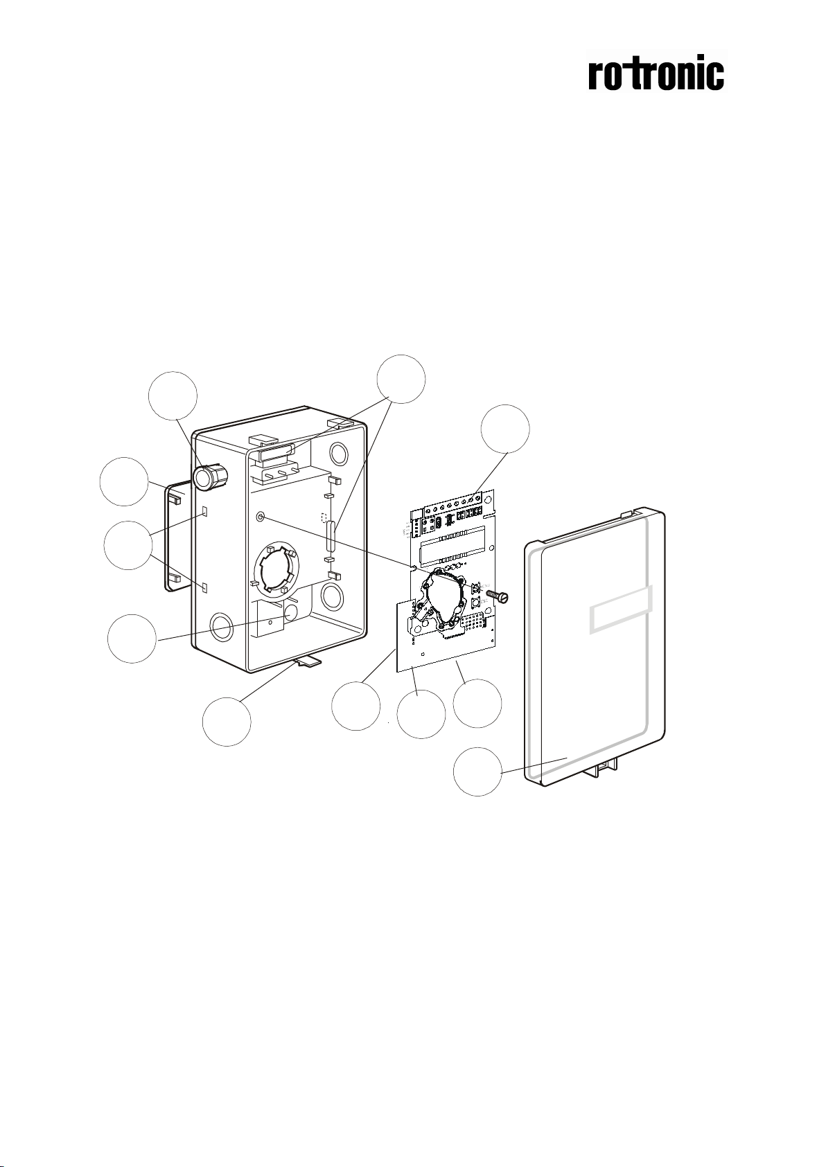
1 Wall plate
5 Carbon monoxide sensor (not
Installation manual
CF8-W-Disp-CO
in industrial wall mounted housing
CO
/ CO sensor with built-in general purpose
2
controller
Fig. 1
2 PCB (Factory supplied
mounted in box)
3 Temperature sensor for
internal compensation (not
shown)
4 RH sensor for internal
compensation (not shown)
shown)
6 Hole for wall plate hooks
7 Snap-in lid
8 Locking screw of the lid (not
shown)
9 PG9 cable entry bushing
10 Air holes
Page 2
Dokument
IMA 208
Rev 1 Page
2 (4)
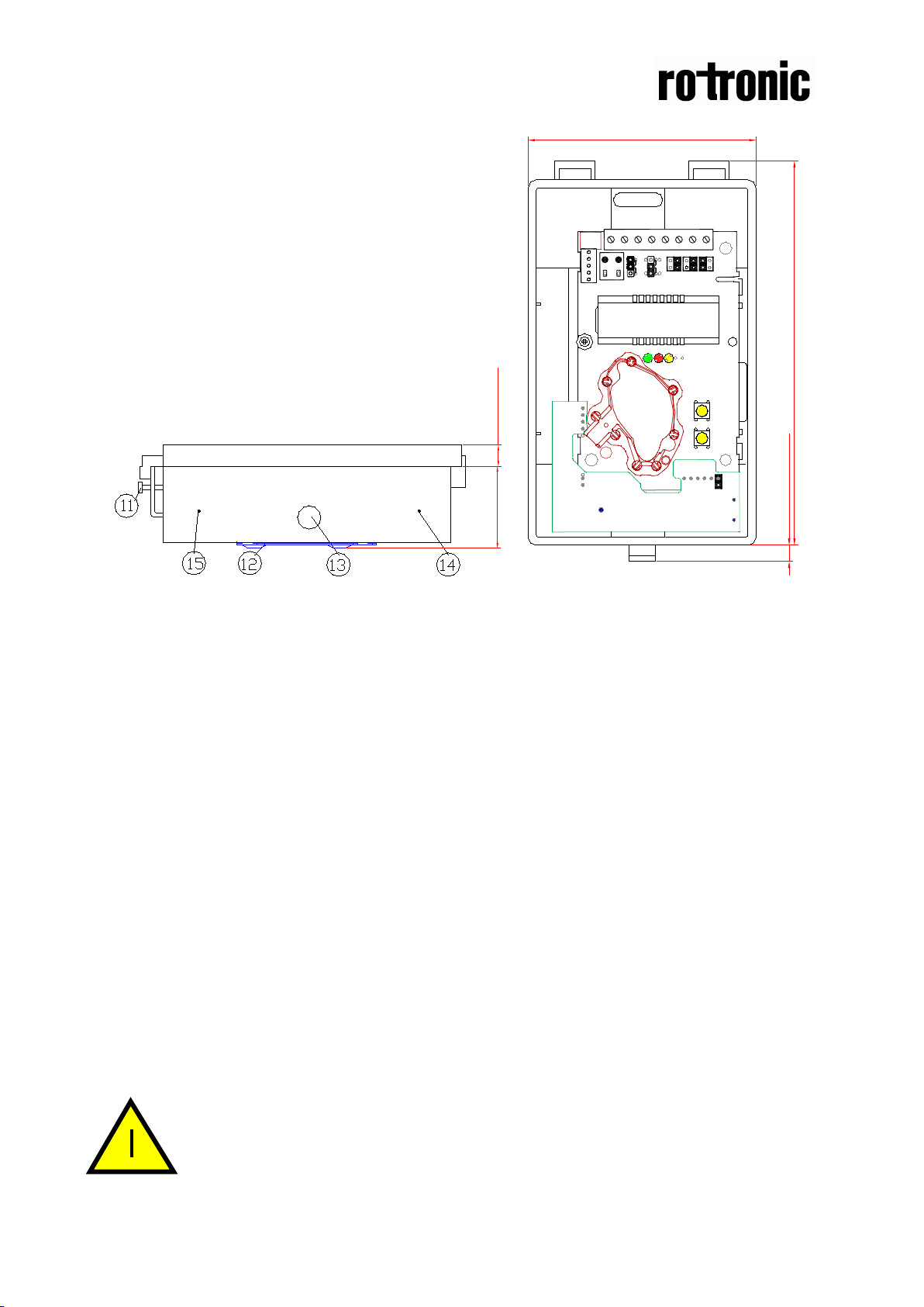
38,5 (1,5)
10 (0,39)
9,5 (0,37)
85 (3,35)
142 (3,58)
Please note! Normally the PCB should not be removed from the
Fig. 2
11 Lid locking screw
12 Wall plate
13 Screw to hold the wall plate
14 Marking to drill hole for PG7
15 Marking to drill hole for PG9
Wall Mounting Instruction
1. Dismount the wall plate. The sensor is delivered with the wall plate mounted.
The wall plate has to be removed before the sensor is mounted onto the wall.
Unscrew the screw on the side of the box. See figure 3.
2. Screw the wall plate onto the wall. The sensor should be mounted 1 to 1,8 m
above the floor. The wall plate has holes for three screws. Drill holes for 3,5mm
screws and put dowel into them. Dowels and screws 3,5 x 25mm are included
in a plastic bag
3. Attach the sensor box to the wall plate. It is done by a snap-in fitting. The wall
plate has three hooks that fit in holes in the sensor box. Fasten the screw on the
side of the box.
4. Electrical cable entry . T he box has a fact ory mounted cable entry bushing in
dimension PG9. Never feed more than one cable through each cable entry
bushing, or else gas might leak through!
The lid can be locked with the screw (11) at the bottom of the sensor box.
housing. If for some reason the PCB must be removed it must be
handled carefully and protec t ed fr om el ect rostatic discharge.
Page 3

Dokument
IMA 208
Rev 1 Page
3 (4)
Terminal
Power (+)
24 VAC/DC+ (+-20%), 3W
2W without output load
Out(1)
Analogue Output 1 (+)
0-10 VDC or 0-20 mA,
Connected to via PTC fuse
According to positions of
6
Normally closed relay
loss
Contact free relay
Triggered by register
8
Analogue Output 4 (+)
0-10 VDC
Max 0,5A, 55VDC / 40VAC
(half-wave rectifier protection)
According to positions of
DI1 Digital Input 1
Closed contact current 1mA
Do not apply any voltage
~
~
Electrical connections
The power supply has to be connected to and . is considered as
system ground. The same ground reference has to be used for the CF8-W-Disp-CO unit
and for any connected devic e! Unless different transformers are used, special
precautions need to be taken.
PLEASE NOTE! The signal ground is not galvanically separated
from the CF8-W-Disp-CO power supply!
PLEASE NOTE! The same ground reference has to be used for
the CF8-W-Disp-CO unit and for the control system!
Connection
Out(2)
5
7
Out(4)
Function
Power ground (-)
Analogue Output 2 (+)
Signal Ground (-)
Open at alarm
situations and power
or Open Collector
Electrical Data
24 VAC/DC-
2-10 VDC or 4-20 mA,
Same as Output 1
minimum load 1mA/5V
rated load 0,5A/125VAC;
1A/24VDC
Remarks
See note 1!
OUT1 jumper and start
point selection.
See note 2!
According to positions of
OUT2 jumper and start
point selection.
See note 2!
See note 1!
OUT3
OUT4.
See note 2 & 3!
Table I. Electrical term ina l connec ti ons for CF8-W-Disp-CO
Note 1: The ground terminal is used as negative power supply DC i nput or AC phase ground
(halfwave rectifier) . The signal ground M, protected by a PTC res istor, is the same as power ground
G0 (permitting a ”3-wire” configuration). A single transformer may be used for the entire system.
Note 2: CF8-W-Disp-CO can deliver both a v oltage or a current loop for Out(1) /Out(2). For Out(4) a
voltage output or an open collect or output is selected with jumper Out(4). T o change between volta ge
and current output mod e the hardware jumper s are used. Ther e is one jumper for Out(1) and one for
Out(2), so that one outp ut can be a v oltage output a nd the ot her a c urrent output. Both, v oltage output
and current output, can ha ve start points 0 % (0-10 VD C or 0-20mA) or 20% (2-10 VDC or 4-20mA)
selected from PC software. See the user manual.
Note 3: Current of Open Collector is internally returned to terminal.
Open contact voltage max 5V
on this input!
Page 4

Dokument
IMA 208
Rev 1 Page
4 (4)
DI1
~
+
Numbers in figure 3
Label or marking
Function
3
Out(1)
CO-transmitter 0-100 ppm CO
4
Out(2)
CO2-transmitter 0-2000 ppm CO2
6, 7
Out(3)
Gas alarm CO >35 ppm or CO2 >1500 ppm
8
Out(4)
Error detected or gas alarm
9, 10
DI 1
Extra terminal. Alarm test function (N.O.)
DI1 Switch
Jumper for
start point
Jumper to
protocol
Jumpers to
current outputs
Jumper to choose
linear signal
for alarm
test
Fig. 3.Terminals and jumpers on CF8-W-Disp-CO. The darker positions are default settings.
configuring the
linear output
start point to
0% or 20%
choose
communication
choose between
voltage or
between open
collector or 0-10V
If more holes are needed the box has several drill markings for holes in two
dimensions, PG7 and PG9. Then fast en t he cabl e entr y bushing and seal properly .
Never feed more than one cable through each cable entry bushing, or else gas might
leak through!
The PCB can be removed during the making of holes. The PCB must be handled
carefully and protected from electrostatic discharge!
Start-up of the CF8-W-Disp-CO
Connect the power directly after mounting. The unit works best if the sensor is
continuously powered. The analogue outputs do not need to be connected before
use. An internal delay function prevents the alarm functions of the relay and OUT4
output during 2 minutes after power up. After short power failures the CO
measurements need this power up time to stabilize. The alarm outputs may be tested
after the 2 minutes delay by shorting the switch DI1. After long power failures the
sensor may need several days to restore the measuring functions.
NOTE! The CO probe gives incorrect readings near some chemicals, e
g silicone. This makes certain environments unsuitable for the sensor.
 Loading...