


 ‘ I Q M ’ & ‘ I Q M L ’ R A N G E
C O N T R O L A N D
M O N I T O R I N G
F A C I L I T I E S
Publication E420E issue 7/02

I Q M - S T A N D A R D F A C I L I T I E S
SPECIFICATION
The type IQM actuator specification is generally as described in Publication No. E410E having a solid state reversing starter in place of the electro-mechanical contactors, suitably rated 4- pole winding, low inertia motor and with the “hammerblow” backlash omitted from the output gear train.
All other standard and optional IQ actuator features are available with IQM modulating actuators subject to the following:
Supply Voltage - maximum 480 volts, 50/60Hz.
Apply for higher voltages up to 575 volts.
Minimum voltage for the size IQM30 is 380 volts, 50/60Hz.
PERFORMANCE
The actuators are suitable for up to 1200 starts per hour with a duty in accordance with IEC 34-1 to S4 50%. See E410E for temperature rating.
CONTROL
Opto-isolators are used to interface the actuator’s internal logic circuits with the remote controls. The basic circuits permit various control facilities to be selected whether internally or externally fed. As standard the actuators are designed for positive switching remote control from digital signals.
Various control functions may be configured on site at the time of commisioning using the Rotork IQ Setting Tool. In the absence of specific instructions, actuators will be dispatched with the control functions configured as shown on the diagram on page 6.
PULSE CONTROL
Where pulse control is used the minimum pulse length should be 18ms and the minimum time between pulses should be 500ms. Typical duration of motor energisation in response to each minimum pulse control signal in the same direction will be between 20 and 30ms. Where special units designed for use with AC remote control supplies are required, the minimum pulse length should be 300ms.
SOLID STATE STARTER
The actuator design incorporates a solid state starter to achieve an increased design life. Five pairs of 1600 volt thyristors switch all three phases of the incoming power supply. Thyristors are considered to be more suitable than triacs for reversing applications and have a higher resistance to transients in the power supply.
The design also includes snubbing and transient protection circuits.
DYNAMIC BRAKING
The facility for dynamic braking is included as standard with the ability to select this function by fitting an electrical link at the actuator terminal block.
POSITIONAL ACCURACY
Repeatability with pulse control is 0.1 output turns.
POWER FUSE
It is essential that the power supply for each actuator is protected by suitably rated high speed fuses mounted at the power distribution panel. The required fuse characteristics are as follows:
|
IQM10 to IQM20 |
IQM25 and IQM35 |
||
Rated current |
10A |
20A |
||
Pre-arcing |
12t 5.4 |
A2s |
12t 30 |
A2s |
Total |
12t 55 |
A2s |
12T 250 |
A2s |
Rated voltage |
660V (IEC) |
660V (IEC) |
||
Suggested fuse |
Ferraz G330010 |
Ferraz K330013 |
||
CIRCUIT DIAGRAM
Standard IQM actuators are in accordance with wiring diagram 5000-000 as shown on page 6.
For aplications requiring seperately mounted starters, please see details of M Range Syncroset actuators given on page 11.
REMOTE CONTROL POWER SUPPLIES
Remote controls may be powered by the internally derived 24 volt DC power supply. Alternatively remote controls may be powered by an external supply of 24DC. The appropriate connections are shown on page 6. Please apply if suitability for other remote control supplies is required.
LOCAL CONTROLS
The actuator is provided with Open, Close and Stop facilities and Local/Remote selection, Local, Open and Close control is configurable to either self-maintained or push-to-run.
EXTERNAL INTERLOCKS
Facilities are provided for the connection of external contacts to inhibit Open and/or Close valve operation.
STATUS FEEDBACK
Four configurable status feedback contacts and monitor relay are available as standard with IQM actuators.
PROTECTION
The motor is protected against single phasing or incorrect phase rotation by the Rotork patented, Syncrophase circuit and against overheating by the thermostat in the motor winding. Opto-isolators provide protection against high voltage transients for the interface with the remote controls.
EMERGENCY SHUTDOWN (ESD)
The ESD facility may be configured for Open or Close operation with the option of by-passing the motor protection thermostat, using the IQ Setting Tool.
3
I Q M - O P T I O N A L F A C I L I T I E S
OPTIONAL FACILITIES
The following optional facilities are available, and are covered by the appropriate alternative wiring diagrams as indicated in the wiring diagram number matrix on page 5.
FOLOMATIC CONTROLLER
The Folomatic enables standard IQM actuators to control the position of a valve in proportion to an analogue current or voltage signal.
A voltage derived from the actuator position sensor is electronically compared with a voltage proportional to the input signal. The difference between them (error) triggers the open or close thyristor circuit, via logic circuits, to drive the actuator in the direction which will cancel the error. Valve position is therefore automatically adjusted in proportion to analogue signal. Unnecessarily frequent switching is prevented by the Motion Inhibit feature.
The Folomatic can be configured to suit the following:
Analogue signals/ |
0-5mA/1k ohm |
0-5v/1 M ohm |
input impedence: |
0-10mA/500 ohm |
0-10v/78 kohm |
|
0-20mA/250 ohm |
0-20V/52 kohm |
Position corresponding |
Closed limit, or percentage Open |
to low input signal: |
or Open limit. |
Position corresponding |
Closed limit, or percentage Open |
to high imput signal: |
or Open limit. |
Deadband: |
0-9.9% of travel between Open |
|
and Closed limit positions. |
Motion Inhibit time: |
2-99 secs. between actuator |
|
movements. |
Action on loss of |
Stay-put or move to high signal |
input signal: |
position or move to low signal |
|
position. Available for minimum |
|
set ‘low’ signal of 0.5mA. |
|
Response on loss of signal will |
|
occur if signal falls below 50% of |
|
set ‘low’ signal. |
Overall accuracy (actuator |
0.5% of maximum signal with |
mechanical output position/ |
dynamic braking and minimum |
demand value): |
of 10 turns for full valve stroke, |
|
assuming a deadband setting of |
|
<0.2%. |
CURRENT POSITION TRANSMITTER (CPT)
The CPT provides an internally powered electrically isolated 4- 20mA analogue valve position feedback signal, which is available at terminals 22 (+ve) and 23 (-ve). The maximum external impedence that may be connected to the signal is 500 ohms. Repeatability is within ±1% and linearity ±2.5% of total valve travel.
ALARM RELAYS
A set of three alarm relays can be provided with the following functions:
Relay 1 ‘Battery low’ signal (Normally open contact rated for 5A 250 volts AC, 30 volts DC).
Relay 2 ‘Thermostat tripped’ signal (change-over contact rated for 30 Watts, 62.5VA, 110 Volts).
Relay 3 ‘Remote selected’ signal (contact as Relay 2)
The following optional facilities available on standard IQ actuators are also available on IQM units.
Negative Switching |
(see publication E120E) |
Interrupter Timer |
(see publication E120E) |
Pakscan |
(see publication S000E) |
CONNECTIONS
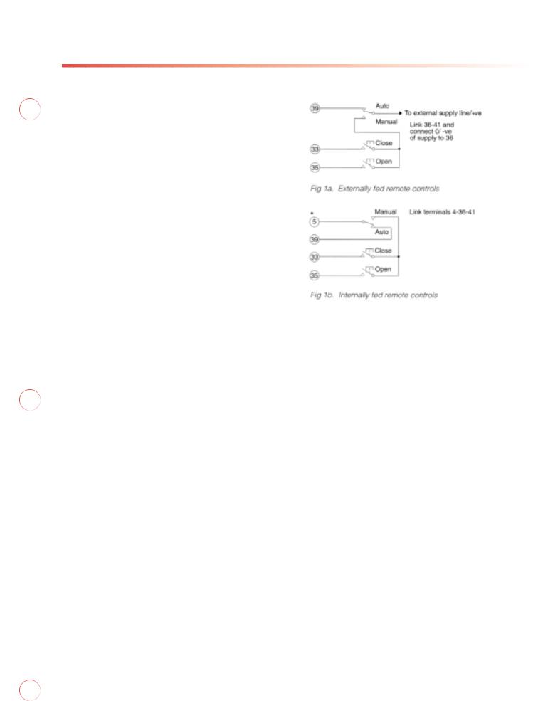
The analogue signal should be connected to terminals 26 (+ve) and 27 (-ve). If no remote manual control is required, link terminals 39 to 5 and 41 to 4. Terminal 39 is provided for remote manual/auto selection. The remote control connections for actuators to standard wiring diagrams are as follows:
 Loading...