


Instruction Manual
748460-B
August 2002
Model 890
UV Analyzer
http://www.processanalytic.com

ESSENTIAL INSTRUCTIONS
READ THIS PAGE BEFORE PROCEEDING!
Rosemount Analytical designs, manufactures and tests its products to meet many national and
international standards. Because these instruments are sophisticated technical products, you
MUST properly install, use, and maintain them to ensure they continue to operate within their
normal specifications. The following instructions MUST be adhered to and integrated into your
safety program when installing, using, and maintaining Rosemount Analytical products. Failure to
follow the proper instructions may cause any one of the following situations to occur: Loss of life;
personal injury; property damage; damage to this instrument; and warranty invalidation.
• Read all instructions prior to installing, operating, and servicing the product.
• If you do not understand any of the instructions, contact your Rosemount Analytical representative
for clarification.
• Follow all warnings, cautions, and instructions marked on and supplied with the product.
• Inform and educate your personnel in the proper installation, operation, and maintenance of
the product.
• Install your equipment as specified in the Installation Instructions of the appropriate
Instruction Manual and per applicable local and national codes. Connect all products to the
proper electrical and pressure sources.
• To ensure proper performance, use qualified personnel to install, operate, update, program, and
maintain the product.
• When replacement parts are required, ensure that qualified people use replacement parts specified by
Rosemount. Unauthorized parts and procedures can affect the product’s performance, place the safe
operation of your process at risk, and VOID YOUR WARRANTY. Look-alike substitutions may result
in fire, electrical hazards, or improper operation.
• Ensure that all equipment doors are closed and protective covers are in place, except when
maintenance is being performed by qualified persons, to prevent electrical shock and personal
injury.
The information contained in this document is subject to change without notice.
Teflon® and Viton® are registered trademarks of E.I. duPont de Nemours and Co., Inc.
Suprasil II® is a registered trademark of Heraeus Amersil Inc.
Pyrex® is a registered trademark of Corning Glass Works.
SNOOP® is a registered trademark of NUPRO Co.
Emerson Process Management
Rosemount Analytical Inc.
Process Analytic Division
1201 N. Main St.
Orrville, OH 44667-0901
T (330) 682-9010
F (330) 684-4434
e-mail: gas.csc@EmersonProcess.com
http://www.processanalytic.com

Model 890
PREFACE...........................................................................................................................................P-1
Definitions ...........................................................................................................................................P-1
Safety Summary .................................................................................................................................P-2
General Precautions For Handling And Storing High Pressure Gas Cylinders .................................P-4
Documentation....................................................................................................................................P-5
Compliances .......................................................................................................................................P-5
1-0 DESCRIPTION AND SPECIFICATIONS..............................................................................1-1
1-1 General Description...............................................................................................................1-1
1-2 Available Options...................................................................................................................1-2
1-3 Specifications ........................................................................................................................1-3
a. General ...........................................................................................................................1-3
b. Sample............................................................................................................................1-3
c. Physical...........................................................................................................................1-4
d. Options............................................................................................................................1-4
Instruction Manual
748460-B
August 2002
TABLE OF CONTENTS
2-0 INSTALLATION ....................................................................................................................2-1
2-1 Check for Shipping Damage.................................................................................................2-1
2-2 Location .................................................................................................................................2-1
2-3 Voltage Requirements...........................................................................................................2-1
2-4 Electrical Connections ...........................................................................................................2-1
a. Line Power Connections .................................................................................................2-1
b. Recorder Connections ....................................................................................................2-2
2-5 Sample Inlet/Outlet Connections.........................................................................................2-3
2-6 Calibration Gas Requirements .............................................................................................2-4
2-7 Sample Handling System ......................................................................................................2-4
2-8 Leak Test Procedure .............................................................................................................2-5
2-9 Sample Flow Rate .................................................................................................................2-5
2-10 Options ..................................................................................................................................2-6
a. Alarm Connections..........................................................................................................2-6
b. Calibration Gas Control Connections.............................................................................2-6
c. Auto Zero/Span Connections.........................................................................................2-7
d. Remote Input/Output Connections..................................................................................2-8
2-11 Ordering Option Kits ..............................................................................................................2-9
3-0 INITIAL STARTUP AND CALIBRATION ............................................................................3-1
3-1 Power Verification..................................................................................................................3-1
3-2 Software/countdown..............................................................................................................3-1
3-3 Front Panel controls and Indicators.......................................................................................3-2
a. Display ............................................................................................................................3-2
b. Function Keys .................................................................................................................3-2
c. User-Programmable Keys...............................................................................................3-3
d. Run Mode Display...........................................................................................................3-4
e. General Display Information ...........................................................................................3-5
3-4 Accessing Mode Displays......................................................................................................3-6
3-5 Security Code ........................................................................................................................3-8
Rosemount Analytical Inc. A Division of Emerson Process Management Contents i

Instruction Manual
748460-B
August 2002
3-6 Range Parameters ................................................................................................................3-9
a. Range Selection..............................................................................................................3-9
b. Linearization....................................................................................................................3-9
c. Component of Interest ....................................................................................................3-9
d. Gain.................................................................................................................................3-9
e. Range, Fullscale .............................................................................................................3-9
f. Calibration Gas ...............................................................................................................3-9
g. Zero Offset ......................................................................................................................3-9
h. Time Constant.................................................................................................................3-10
3-7 Analyzer Diagnostics .............................................................................................................3-12
3-8 Zero Calibration .....................................................................................................................3-13
3-9 Zero Calibration For The Analyzer With The Cal Gas Control Option ..................................3-13
3-10 Span Calibration ....................................................................................................................3-13
3-11 Span Calibration For The Analyzer With The Cal Gas Control Option .................................3-14
3-12 Linearization ..........................................................................................................................3-15
a. All Range.........................................................................................................................3-17
b. Non-Standard Ranges and Coefficients .........................................................................3-17
3-13 Alarm .....................................................................................................................................3-19
a. STATUS Display .............................................................................................................3-21
3-14 Current Output.......................................................................................................................3-22
3-15 Auto Zero/Span .....................................................................................................................3-23
3-16 Remote Range Input/Output..................................................................................................3-26
3-17 Interference Balance .............................................................................................................3-28
a. SO
b. Cl
Model 890
Measurement...........................................................................................................3-28
2
Measurement ............................................................................................................3-28
2
4-0 ROUTINE OPERATION AND THEORY ...............................................................................4-1
4-1 Routine Operation .................................................................................................................4-1
4-2 Recommended Calibration Frequency..................................................................................4-1
4-3 Shutdown...............................................................................................................................4-1
4-4 Detection System Theory ......................................................................................................4-1
5-0 TROUBLESHOOTING ..........................................................................................................5-1
5-1 Error Code Summary.............................................................................................................5-1
5-2 Iris Balance Adjustment.........................................................................................................5-2
5-3 Voltage Checks .....................................................................................................................5-2
5-4 Digital Gain Adjustment .........................................................................................................5-2
5-5 Case Heater ..........................................................................................................................5-2
5-6 ERL Error Message ...............................................................................................................5-3
6-0 MAINTENANCE ....................................................................................................................6-1
6-1 Cell Removal, Cleaning And Replacement ...........................................................................6-1
a. Cell Cleaning...................................................................................................................6-1
6-2 UV lamp .................................................................................................................................6-3
a. Replacement ...................................................................................................................6-3
b. Realignment....................................................................................................................6-7
6-3 Cleaning Optical Components...............................................................................................6-9
a. Spectrally Selective Mirrors ............................................................................................6-9
b. Beam Splitter/Focusing Mirrors.......................................................................................6-9
c. Source Envelope.............................................................................................................6-9
d. End Caps ........................................................................................................................6-9
ii Contents Rosemount Analytical Inc. A Division of Emerson Process Management

Model 890
6-4 Electronic Circuitry.................................................................................................................6-10
a. Power Supply Board .......................................................................................................6-10
b. Signal Board....................................................................................................................6-10
c. Preamplifier Board ..........................................................................................................6-10
d. Adapter Board.................................................................................................................6-10
e. Micro Board.....................................................................................................................6-10
f. Micro Board Replacement ..............................................................................................6-10
g. Case Heater Temperature Control..................................................................................6-10
h. Dual Alarm/Calibration Gas Control Board (Option).......................................................6-10
i. Isolated Remote Range I/O Board (Option)....................................................................6-11
j. Auto Zero/Span Board (Option) ......................................................................................6-11
7-0 REPLACEMENT PARTS ......................................................................................................7-1
7-1 Matrix .....................................................................................................................................7-1
7-2 Circuit Board Replacement Policy .........................................................................................7-2
7-3 Selected Replacement Parts.................................................................................................7-2
7-4 Lamp Replacement ...............................................................................................................7-3
8-0 RETURN OF MATERIAL ......................................................................................................8-1
8-1 Return Of Material .................................................................................................................8-1
8-2 Customer Service ..................................................................................................................8-1
8-3 Training..................................................................................................................................8-1
Instruction Manual
748460-B
August 2002
Rosemount Analytical Inc. A Division of Emerson Process Management Contents iii

Instruction Manual
748460-B
August 2002
Figure 1-1. Model 890 Optical Bench....................................................................................... 1-2
Figure 2-1. Power Supply Board .............................................................................................. 2-2
Figure 2-2. Cable Gland Connection........................................................................................ 2-3
Figure 2-3. Calibration Gas Control and Alarm Connections................................................... 2-6
Figure 2-4. Auto Zero/Span Connections................................................................................. 2-7
Figure 2-5. Remote Input/Output Options ................................................................................ 2-8
Figure 3-1. Model 890 Adjustments Locations......................................................................... 3-1
Figure 3-2. Model 890 Keypad................................................................................................. 3-2
Figure 3-3. Run Mode Display ................................................................................................. 3-4
Figure 3-4. Logic Flow Chart.................................................................................................... 3-7
Figure 3-5. Security Mode Flow Diagram................................................................................. 3-8
Figure 3-6. Range Mode Flow Diagram ................................................................................. 3-11
Figure 3-7. Diagnostics Mode Flow Diagram......................................................................... 3-12
Figure 3-8. Linearizer Mode Flow Diagram............................................................................ 3-15
Figure 3-9. Typical Application Linearization Curve............................................................... 3-16
Figure 3-10. Concentration Curve............................................................................................ 3-18
Figure 3-11. Curve, Normalized ............................................................................................... 3-18
Figure 3-12. Alarm Mode Flow Diagram .................................................................................. 3-20
Figure 3-13. Status Display......................................................................................................3-21
Figure 3-14. Current Output Mode ........................................................................................... 3-22
Figure 3-15. Auto Zero/Span Flow Diagram ............................................................................ 3-25
Figure 3-16. Remote Input/Output Flow Diagram .................................................................... 3-26
Figure 4-1. Model 890 Timing Diagram.................................................................................... 4-2
Figure 6-1. Optical Bench ........................................................................................................6-2
Figure 6-2. Sample Cell Assembly........................................................................................... 6-3
Figure 6-3. Collector Block (Exploded View)............................................................................ 6-5
Figure 6-4. Detector Block (Exploded View) ............................................................................ 6-6
Figure 6-5. Lamp Assembly 655000 ........................................................................................ 6-7
Figure 6-6. Lamp Alignment..................................................................................................... 6-8
Figure 7-1. Model 890 Component Locations.......................................................................... 7-4
Figure 7-2. Optical Bench - Sensor Locations ......................................................................... 7-5
Figure 7-3. UV Lamp Life vs. Intensity ..................................................................................... 7-5
Model 890
LIST OF ILLUSTRATIONS
LIST OF TABLES
Table 3-1. Linearization Coefficients, Standard SO2 Ranges ............................................... 3-16
Table 3-2. Remote Range I/O Designation........................................................................... 3-27
Table 3-3. Remote Range I/O Binary and Decimal Coding .................................................. 3-27
Table 5-1. Error Code Summary............................................................................................. 5-1
Table 6-1. Jumper Configuration for Options........................................................................ 6-11
iv Contents Rosemount Analytical Inc. A Division of Emerson Process Management

Model 890
623782 Schematic Diagram, Micro Board
624127 Schematic Diagram, Adaptor Board
624204 Schematic Diagram, Dual Alarm/Fail Safe Alarm
624251 Schematic Diagram, Remote Control
624599 Scheamtic Diagram, Auto/Zero Span
652687 Schematic Diagram, Signal Board SO
652715 Diagram, Electrical Interconnect SO
652807 Schematic Diagram, Power Supply Board
652857 Schematic Diagram, Preamplifier Board SO
654853 Installation Drawing, Model 890
656137 Schematic Diagram, Signal Board Cl
656138 Schematic Diagram, Preamplifier Board Cl
656911 Diagram, Electrical Interconnect Cl
Instruction Manual
748460-B
August 2002
LIST OF DRAWINGS
2
2
2
2
2
2
Rosemount Analytical Inc. A Division of Emerson Process Management Contents v

Instruction Manual
748460-B
August 2002
Model 890
vi Contents Rosemount Analytical Inc. A Division of Emerson Process Management

Instruction Manual
Model 890
PREFACE
The purpose of this manual is to provide information concerning the components,
functions, installation and maintenance of the Model 890 UV Analyzer.
Some sections may describe equipment not used in your configuration. The user should
become thoroughly familiar with the operation of this module before operating it. Read
this instruction manual completely.
DEFINITIONS
The following definitions apply to DANGERS, WARNINGS, CAUTIONS and NOTES found throughout
this publication.
DANGER .
748460-B
August 2002
Highlights the presence of a hazard which will cause severe personal injury, death, or substantial
property damage if the warning is ignored.
WARNING .
Highlights an operation or maintenance procedure, practice, condition, statement, etc. If not
strictly observed, could result in injury, death, or long-term health hazards of personnel.
CAUTION.
Highlights an operation or maintenance procedure, practice, condition, statement, etc. If not
strictly observed, could result in damage to or destruction of equipment, or loss of effectiveness.
NOTE
Highlights an essential operating procedure,
condition or statement.
Rosemount Analytical Inc. A Division of Emerson Process Management Preface P-1

Instruction Manual
748460-B
August 2002
Model 890
SAFETY SUMMARY
To avoid explosion, loss of life, personal injury and damage to this equipment and on-site property,
all personnel authorized to install, operate and service the Model 890 Analyzer should be
thoroughly familiar with and strictly follow the instructions in this manual. Save these instructions.
If this equipment is used in a manner not specified in these instructions, protective systems may be
impaired.
DANGER.
ELECTRICAL SHOCK HAZARD
Do not operate without doors and covers secure. Servicing requires access to live parts which can
cause death or serious injury. Refer servicing to qualified personnel.
For safety and proper performance this instrument must be connected to a properly grounded
three-wire source of power.
Alarm and zero/span switching relay contacts wired to separate power sources must be disconnected before servicing.
This instrument is shipped from the factory set up to operate on 115 volt, 50/60 Hz electric power.
For operation on 230 volt, 50/60 Hz power, see Section 2-8 on page 2-5 for modifications.
WARNING.
POSSIBLE EXPLOSION HAZARD
This analyzer is of a type capable of analysis of sample gases which may be flammable. If used for
analysis of such gases, the instrument must be protected by a continuous dilution purge system in
accordance with Standard ANSI/NFPA 496-1989, Chapter 8.
If explosive gases are introduced into this analyzer, the sample containment system must be carefully leak-checked upon installation and before initial startup, during routine maintenance and any
time the integrity of the sample containment system is broken, to ensure the system is in leak-proof
condition. Leak-check instructions are provided in Section 2-8 on page 2-5.
WARNING
PARTS INTEGRITY
Tampering or unauthorized substitution of components may adversely affect safety of this product.
Use only factory documented components for repair.
P-2 Preface Rosemount Analytical Inc. A Division of Emerson Process Management

Instruction Manual
Model 890
WARNING.
INTERNAL ULTRAVIOLET LIGHT HAZARD
Ultraviolet light from the source lamp can cause permanent eye damage. Do not look at the UV
source for prolonged periods. Use of UV filtering glasses is recommended.
WARNING .
HIGH PRESSURE GAS CYLINDERS
This analyzer requires periodic calibration with known zero and standard gases. See General Precautions for Handling and Storing High Pressure Cylinders, on page 4.
WARNING
TOXIC GAS HAZARD
748460-B
August 2002
This instrument measures toxic gases. Ensure gas lines are leak-free and properly vented. Inhalation of toxic gases is highly dangerous and could result in death.
Also, exhaust gas from this instrument is toxic and equally dangerous. Exhaust must be connected
either to its original source or an appropriate outside vent using ¼-inch (6mm) tubing minimum.
CAUTION
TOPPLING HAZARD
This instrument’s internal pullout chassis is equipped with a safety stop latch located on the left
side of the chassis.
When extracting the chassis, verify that the safety latch is in its proper (counter-clockwise) orientation.
If access to the rear of the chassis is required, the safety stop may be overridden by lifting the
latch; however, further extraction must be done very carefully to insure the chassis does not fall
out of its enclosure.
If the instrument is located on top of a table or bench near the edge, and the chassis is extracted, it
must be supported to prevent toppling.
Failure to observe these precautions could result in personal injury and/or damage to the product.
Rosemount Analytical Inc. A Division of Emerson Process Management Preface P-3

Instruction Manual
748460-B
August 2002
Model 890
GENERAL PRECAUTIONS FOR HANDLING AND STORING HIGH
PRESSURE GAS CYLINDERS
Edited from selected paragraphs of the Compressed Gas Association's "Handbook of Compressed
Gases" published in 1981
Compressed Gas Association
1235 Jefferson Davis Highway
Arlington, Virginia 22202
Used by Permission
1. Never drop cylinders or permit them to strike each other violently.
2. Cylinders may be stored in the open, but in such cases, should be protected against extremes of weather
and, to prevent rusting, from the dampness of the ground. Cylinders should be stored in the shade when
located in areas where extreme temperatures are prevalent.
3. The valve protection cap should be left on each cylinder until it has been secured against a wall or bench, or
placed in a cylinder stand, and is ready to be used.
4. Avoid dragging, rolling, or sliding cylinders, even for a short distance; they should be moved by using a
suitable hand-truck.
5. Never tamper with safety devices in valves or cylinders.
6. Do not store full and empty cylinders together. Serious suckback can occur when an empty cylinder is
attached to a pressurized system.
7. No part of cylinder should be subjected to a temperature higher than 125
permitted to come in contact with any part of a compressed gas cylinder.
8. Do not place cylinders where they may become part of an electric circuit. When electric arc welding,
precautions must be taken to prevent striking an arc against the cylinder.
°
F (52°C). A flame should never be
P-4 Preface Rosemount Analytical Inc. A Division of Emerson Process Management

Instruction Manual
Model 890
DOCUMENTATION
The following Model 890 instruction materials are available. Contact Customer Service Center or the local
representative to order.
748460 Instruction Manual (this document)
COMPLIANCES
MODEL 890 SO2 ANALYZER
748460-B
August 2002
The Model 890 SO
locations. When equipped with the optional Type Z Purge Kit (PN 624446), this analyzer is approved for
use in Class I, Division 2, Groups B, C, and D hazardous locations and use indoor non-hazardous locations
when sampling flammable gases.
Rosemount Analytical has satisfied all obligations from the European Legislation to harmonize the product
requirements in Europe.
This product complies with the standard level of NAMUR EMC. Recommendation (May 1993).
Analyzer is intended for sampling only non-hazardous gases in non-hazardous
2
97-C209
NAMUR
This product satisfies all obligations of all relevant standards of the EMC framework in Australia and New
Zealand.
N96
MODEL 890 CL
The Model 890 Cl
locations. When equipped with the optional Type Z Purge Kit (PN 624446), this analyzer is approved
for use in Class I, Division 2, Groups B, C, and D hazardous locations and use indoor non-hazardous
locations when sampling flammable gases.
ANALYZER
2
Analyzer is intended for sampling only non-hazardous gases in non-hazardous
2
FM
APPROVED
Rosemount Analytical Inc. A Division of Emerson Process Management Preface P-5

Instruction Manual
748460-B
August 2002
Model 890
P-6 Preface Rosemount Analytical Inc. A Division of Emerson Process Management

Model 890
Instruction Manual
748460-B
August 2002
SECTION 1
DESCRIPTION AND SPECIFICATIONS
1-1 GENERAL DESCRIPTION
The Model 890 Ultraviolet Analyzer is
designed to determine continuously the
concentration of the component of interest
a flowing gaseous mixture. The analyzer is
capable of measurement in the 50 to 5,000
ppm range for SO
.
Cl
2
and 100 to 5,000 ppm for
2
Optical Bench
The ultraviolet source emits a pulsed (30 Hz)
beam of energy. This energy is split by a
beam splitter, each beam being directed to
pairs of detectors before and after the sample
cell.
One of the unique features of the Model 890
is the use of spectrally selective,
“Transflectance”© mirrors. These mirrors
isolate the sample and reference spectral
passbands for the detectors. They reflect
energy below a wavelength region and
transmit the remaining, higher wavelengths,
all with much lower energy loss than the more
commonly used bandpass interference filters.
Four detectors are used in this system, two
before the sample cell (sample before [S
and reference before [R
b]) and two after
(sample after [Sa] and reference after [Ra]).
S
b and Sa receive energy in the specific
wavelength regions depending on the
application (265 to 310 nm for SO
355 nm for Cl
nm region for SO
), Rb and Ra in the 310 to 355
2
and 355 to 400 nm for Cl2.
2
, 310 to
2
COI = [f(R
b)-Sb]-[f(Ra)-Sa]
where:
in
Ra, Rb, Sa, Sb = signals from those
detectors so identified
f = attenuation factor for the reference
signal, adjusted to compensate for NO
2
interference.
The sample gas is introduced to the sample
cell, and the COI absorbs ultraviolet energy in
proportion to the concentration in the gas. The
difference between the signals of the
detectors located at both ends of the sample
cell determines the concentration of COI
in
the sample.
Additionally, the adjacent (non-COI
-
absorbing) reference wavelengths are used
as a baseline for measurement and correction
of sample interferent components, particularly
NO
2.
Readout is on a 16-character,
LED-backlighted liquid crystal display. COI
concentration data is presented in parts per
b]
million, percent of composition, or percent of
fullscale. Additionally, 0 to +5 VDC output for
a potentiometric (voltage) recorder and 0 to
20 mA or 4 to 20 mA isolated current output
(maximum load 700 ohms) are provided as
standard.
A case heater with fan assembly maintains
proper operating temperature.
These four detectors measure the component
of interest (COI) concentration and correct for
NO
2 interference and UV lamp fluctuations.
The difference between detector
determinations is the COI concentration,
following this formula:
Rosemount Analytical Inc. A Division of Emerson Process Management Description and Specifications 1-1
Linearization
A linearizer, based on a fourth-order
polynomial, is incorporated in the electronic
circuitry. By turning the linearizer ON and
entering the correct coefficients, an output
linear with concentration is obtained.

Instruction Manual
748460-B
August 2002
Model 890
DETECTORS
a
MIRROR
TRANSFLECTANCE©
MIRRORS
a
TRANSFLECTANCE©
MIRRORS
SAMPLE CELL
BEAM SPLITTER
UV LAMP
Figure 1-1. Model 890 Optical Bench
DETECTORS
b
b
MIRRORS
1-2 AVAILABLE OPTIONS
Operation of the Model 890 can be enhanced
with the choice of several options:
Dual Alarms (standard and fail-safe)
User-set dual alarms are available with
configurable HI/LO designations and
deadband.
Auto Zero/Span
An Automatic Zero/Span Option is available
for unattended calibration of all three ranges.
Remote Range I/O
An optional remote range input/output is
available.
Air Purge Kit
Air purge kit, when installed with
user-supplied components, meets Type Z
requirements of standard ANSI/NFPA
496-1993 for installation in Class I, Division 2
locations as defined in the National Electrical
Code (ANSI/NFPA 70) when sampling
nonflammable gases. If the analyzer is used
to sample a flammable gas, it must be
protected by a continuous dilution purge
Calibration Gas Control
A Calibration Gas Control Option allows two
solenoids to be remotely actuated from the
front panel, enabling one-man calibration
system per standard ANSI/NFPA 496-1993,
Chapter 6, or IEC publication 79-2-1983,
Section Three. (Consult Customer Service
Center, page 8-1, for further information.)
without leaving the analyzer.
1-2 Description and Specifications Rosemount Analytical Inc. A Division of Emerson Process Management

Model 890
1-3 SPECIFICATIONS
Instruction Manual
748460-B
August 2002
a. General
1
Range (Std) (fullscale).................. 0 to 50, 0 to 5000 ppm SO2 at atmospheric pressure
0 to 100 to 0 to 5000 ppm Cl
Operating Temperature ................. SO
Cl
applications: 32°F to 104°F (0°C to 40°C)
2
applications: 59°F to 95°F (15°C to 35°C)
2
at atmospheric pressure
2
Repeatability.................................. ≤1% of fullscale
2
Zero Drift
Span Drift
...................................... SO2: ±2% of fullscale per week
2
..................................... SO2: ±2% of fullscale per week
Cl2: ±2% of fullscale per 24 hours
: ±2% of fullscale per 24 hours
Cl
2
Noise ............................................. ≤1% of fullscale
Response Time
(Electronic) ................................ Variable, 90% of fullscale in 0.5 sec. to 20 sec, field selectable
(application dependent)
Sensitivity ...................................... SO
Interferent Rejection ...................... Discrimination ratio for NO
: ≤0.1 ppm
2
: ≤0.2 ppm
Cl
2
2 is 1000:1 for SO
applications
2
Analog Output................................ Standard: 0 to 5 VDC and 0 to 20 mA/4 to 20 mA DC, isolated
(maximum load 700 ohms)
Linearization .................................. Keypad entered coefficients for linearizing 1, 2 or (all) 3 ranges
Power Requirements..................... 115/230 VAC ±10%, 50/60 Hz, 350 Watts
b. Sample
Sample Cell ................................... 12.0 inches (305 mm) long, 110 cc volume
Materials in Contact with Sample
Windows ................................ Suprasil II
Cells....................................... Pyrex
Tubing.................................... FEP Teflon
Fittings ................................... 316 Stainless Steel
O-Rings.................................. Viton-A
Sample Pressure........................... Maximum 10 psig (69 kPa)
1
Performance specifications based on recorder output.
2.
Performance specifications based on ambient temperature shifts of less than 20° Fahrenheit (11° Celsius) per hour.
Rosemount Analytical Inc. A Division of Emerson Process Management Description and Specifications 1-3

Instruction Manual
748460-B
August 2002
c. Physical
Model 890
Enclosure....................................... General purpose for installation in weather-protected area.
Optional purge kit per Type Z, ANSI/NFPA 496-1993
Dimensions.................................... 8.7 x 19 x 24 inches (221 x 483 x 610 mm) H x W x D
Weight ........................................... 65 lbs. (30 kg)
d. Options
2
Alarm
........................................... Two single point, field programmable high or low, deadband up to
20% of fullscale
Alarm Relay Contacts............ Two Form C contact rated 3A, 125/250 VAC or 5A, 30 VDC
(resistive)
Calibration Gas Control ................. Two front panel actuated contact closures
Relay Outputs........................ Two Form C contact rated 3A, 125/250 VAC or 5A, 30 VDC
(resistive)
Auto Zero/Span ............................. Four form C contact closures, rated 3A, 125/250 VAC or 5A, 30
VDC (resistive), field programmable frequency and duration of
closure
Relay Outputs........................ Two form A contact closures for indication of insufficient zero and
span adjustment, rated (resistive load):
Max. switching power: 10 Watts
Max. switching voltage: 30 VDC
Max. switching current: 0.5 A
Remote Input/Output ..................... Three remotely changeable ranges with positive identification.
Range Change ...................... Binary or decimal, field selectable.
Auto Zero/Span ..................... Auto Cal request and status.
Relay Outputs........................ Eight form A contact rated (resistive load):
Max. switching power: 10 Watts
Max. switching voltage: 30 VDC
Max. switching current: 0.5 A
Inputs ..................................... Eight optical couplers
Input Range ........................... +5 VDC to +24 VDC
1
1
When installed with user-supplied components, meets requirements for Class I, Division 2 locations per National Electrical
Code (ANSI/NFPA 70) for analyzers sampling nonflammable gases. Analyzers sampling flammable gases must be
protected by a continuous dilution purge system in accordance with Standard ANSI/NFPA 496-1993, Chapter 6. Consult
factory for recommendations.
2
Fail-safe jumper configuration.
1-4 Description and Specifications Rosemount Analytical Inc. A Division of Emerson Process Management

Model 890
Instruction Manual
748460-B
August 2002
SECTION 2
INSTALLATION
2-1 CHECK FOR SHIPPING DAMAGE
Examine the shipping carton and contents
carefully for any signs of damage. Save the
carton and packing material until the analyzer
is operational. If carton or contents damage
(either external or concealed) is discovered,
notify the carrier immediately.
2-2 LOCATION
Locate the analyzer in a weather-protected,
non-hazardous location free from vibration.
For best results mount the analyzer near the
sample stream to minimize sample-transport
time. Refer to Installation Drawing 654853.
If equipped with PN 624446 optional air purge
kit and installed with user-provided
components per Instructions 748157, the
analyzer may be located in a Class I, Division
2 area as defined by the National Electrical
Code (ANSI/NFPA 70). This kit is designed to
provide Type Z protection in accordance with
Standard ANSI/NFPA 496-1993, Chapter 2,
when sampling nonflammable gases. For
flammable samples, the instrument must be
equipped with a continuous dilution purge
system in accordance with ANSI/NFPA
496-1993, Chapter 6. Consult factory for
recommendations concerning minimum purge
flow requirements for your particular
application.
2-3 VOLTAGE REQUIREMENTS
WARNING
ELECTRICAL SHOCK HAZARD
For safety and proper performance this instrument must be connected to a properly
grounded three-wire source of electrical
power.
This instrument was shipped from the factory
set up to operate on 115 VAC, 50/60 Hz
electric power. For operation on 230 VAC,
50/60 Hz the installer must position voltage
select switches S1 and S2 located on power
supply board to the 230 VAC position (see
Figure 2-1 on page 2-2).
Power consumption is 350 watts.
2-4 ELECTRICAL CONNECTIONS
The power, recorder and current output cable
glands are shipped already installed to allow
attachment of cables to connectors or terminal
strips. Cable glands for specific cables are as
follows:
CABLE GLAND PART NO.
Power 899330
Recorder 899329
Current Output 899329
Remove the rear cover to access the
terminals. Route each cable through the
cable gland and connect to appropriate
connector or terminal strip as shown in
Drawings 654853 and 652715. Then, tighten
the gland.
a. Line Power Connections
If this instrument is located on a bench or
table top or is installed in a protected
rack, panel or cabinet, power may be
connected to it via a 3-wire flexible power
cord, minimum 18 AWG (max. O.D.
0.480", min. O.D. 0.270") through hole
“F” (refer to Drawing 654853) utilizing the
connector gland (PN 899330) provided.
Accessory kits are available which include
one of the following: 1) a 10-foot North
American power cord set and four
enclosure support feet (PN 654008) for
bench top use, 2) the power cord only
(PN 634061), or 3) the four feet only (PN
634958). If the instrument is permanently
mounted in an open panel or rack, use
electrical metal tubing or conduit.
Rosemount Analytical Inc. A Division of Emerson Process Management Installation 2-1

Instruction Manual
2TP3
748460-B
August 2002
Model 890
Refer to Figure 2-2 on page 2-3 and
Drawings 654853, 652715 and 656139.
Route the power cable through the cable
gland and connect the leads to TB1. After
connecting the leads, tighten the cable
gland adequately to prevent rotation or
slippage of the power cable. Since the
rear terminals do not slide out with the
chassis, no excess power cable slack is
necessary.
b. Recorder Connections
Recorder connections are made to the
rear panel. Refer to Drawings 654853,
652715 and 656139. Route the recorder
cable through the cable gland and
connect to TB2.
S1 S2
TP4 TP5
Recorder and interconnection cables
should meet the following requirements:
Voltage Output: 0 to +5 VDC
•
Maximum distance from recorder to
analyzer: 1000 ft. (305 m)
•
Recorder input impedance: >5000
ohms
•
Customer-supplied cable:
2-conductor, 20 AWG (min.), shielded
Isolated Current Output: 0 to 20 mA or
4 to 20 mA (keyboard programmable)
•
Maximum load impedance: 700 ohms
E1
E1
S1
115 115
J11
1
HEATER
J16
1
BACKLIGHT
230V
115V
F1
+
S2
+
J8
LAMP
K1
J9
1
HEATSINK
J2
1
1
FAN
+
+
+ +
1
J7
+
++
J13
+
+ +
+
+
652810
POWER SUPPLY
+
+
1
+
+
+
+
+
TP1
TP
ZERO
SPAN
TEMP
SENSOR
J5
D6
Figure 2-1. Power Supply Board
2-2 Installation Rosemount Analytical Inc. A Division of Emerson Process Management

Model 890
INTERIOR EXTERIOR
Nut Gland Nut
Cable
Figure 2-2. Cable Gland Connection
2-5 SAMPLE INLET/OUTLET CONNECTIONS
The standard Model 890 is intended for
atmospheric pressure operation only, and
must be vented to either the atmosphere or a
collection destination at atmospheric
pressure. Sample inlet and outlet connections
are located on the rear panel. All connections
are 1/4-inch ferrule-type compression fittings.
See Drawing 654853.
WARNING
TOXIC GAS HAZARD
This instrument measures toxic gases.
Ensure gas lines are leak-free and properly
vented. Inhalation of toxic gases is highly
dangerous and could result in death.
Also, exhaust gas from this instrument is
toxic and equally dangerous. Exhaust
must be connected either to its original
source or an appropriate outside vent using ¼-inch (6mm) tubing minimum.
Instruction Manual
748460-B
August 2002
Case Wall
WARNING
POSSIBLE EXPLOSION HAZARD
This analyzer is of a type capable of analysis of sample gases which may be flammable. If used for analysis of such gases,
the instrument must be protected by a
continuous dilution purge system in accordance with Standard ANSI/NFPA 4961989, Chapter 8.
If explosive gases are introduced into this
analyzer, the sample containment system
must be carefully leak-checked upon installation and before initial startup, during
routine maintenance and any time the integrity of the sample containment system
is broken, to ensure the system is in leakproof condition. Leak-check instructions
are provided in Section 2-8 on page 2-5.
Internal leaks resulting from failure to observe these precautions could result in an
explosion causing death, personal injury
or property damage.
Rosemount Analytical Inc. A Division of Emerson Process Management Installation 2-3

Instruction Manual
748460-B
August 2002
Model 890
2-6 CALIBRATION GAS REQUIREMENTS
Analyzer calibration consists of setting a zero
point and one or more upscale points.
All applications require a zero standard gas to
set the zero point on the display or recorder
chart. If the factory Calibration and Data
Sheet (included with the drawings at the end
of the manual) specifies a background gas,
use this as the zero gas. If a background gas
is not specified, use dry nitrogen for the zero
gas. Ideally, span gas should be between
75 % and 100 % of the fullscale span.
2-7 SAMPLE HANDLING SYSTEM
Many different sample handling systems are
available, either assembled completely or as
loose components. The type used depends
on the requirements of the particular
application and the preferences of the
individual user. Typically, the sample
handling system incorporates such
components as pumps and valves to permit
selection of sample, zero standard and
upscale standard gas; needle valve in
sample-inlet line for flow adjustment;
flowmeter for flow measurement and/or
indication of flow stoppage; and filter(s) to
remove particulate matter.
2-4 Installation Rosemount Analytical Inc. A Division of Emerson Process Management

Model 890
Instruction Manual
748460-B
August 2002
2-8 LEAK TEST PROCEDURE
WARNING
POSSIBLE EXPLOSION HAZARD
This analyzer is capable of analyzing sample gases which may be flammable. If
used for analysis of such gases the instrument must be protected by a continuous dilution purge system in accordance
with Standard ANSI/NFPA 496-1989 (Chapter 8).
If explosive gases are introduced into the
analyzer, the sample containment system
must be leak checked upon installation
and before initial startup, during routine
maintenance and any time the integrity of
the sample containment system is broken,
to ensure that the system is in leak proof
condition.
Internal leaks resulting from failure to observe these precautions could result in an
explosion causing death, personal injury
or property damage.
The following test is designed for sample
pressure up to 10 psig (69 kPa).
NOTE
Do not allow test liquid to contaminate cell
or detectors and UV source windows.
Should this occur, follow instructions in
Section 6-1 on page 6-1 to clean the cell.
2-9 SAMPLE FLOW RATE
Recommended sample flow rate is 1 to 2
SCFH (500 to 1000 cc/min). A subnormal
flow rate will not affect readings but may result
in an undesirable time lag. However, an
excessive flow rate can result in cell
pressurization.
Assume that two cell volumes are required to
flush any cell. Approximate flushing time for
the Model 890's 12-inch cell at atmospheric
sampling pressure (i.e., the outlet of the cell
venting to atmosphere) is approximately 12
seconds.
Flushing time is inversely proportional to flow
rate.
The primary effect of flow rate, other than
flushing time, is cell pressure. Due to
restrictions in exit flow configuration, an
increasing flow rate increases sample
pressure in the cell.
1. Supply air or inert gas such as nitrogen at
10 psig (69 kPa) to analyzer via a flow
indicator with a range of 0 to 250 cc/min
and set flow rate at 125 cc/min to the
sample inlet.
2. Seal off sample outlet with a cap.
3. Use a suitable test liquid such as SNOOP
(PN 837801) to detect leaks. Cover all
fittings, seals or possible leak sources.
4. Check for bubbling or foaming which
indicates leakage and repair as required.
Any leakage must be corrected before
introduction of sample and/or application
of electrical power.
Rosemount Analytical Inc. A Division of Emerson Process Management Installation 2-5
In all cases, the effect of pressure on readout
is eliminated if the same flow rate is used for
the measured sample as well as for the zero
gas and span gas.
Note that at higher flow rates the nonlinearity
of the calibration curve increases, because of
increase in sample cell pressure. Therefore, if
higher flow rates are required, the calibration
curve should be redrawn at the higher rate.
At flows up to 2 CFH (1 L/min), gaseous
sample temperatures are equilibrated to
instrument temperature regardless of stream
temperature. At extremely high flow rates,
this may not be true, but no such effect has
been noted up to 18 CFH (9 L/min).

Instruction Manual
748460-B
August 2002
Model 890
2-10 OPTIONS
The following options may be ordered factory
installed or may be ordered as kits from the
factory at a later date: Alarm, Calibration Gas
Control, Auto Zero/Span and Remote Range
I/O. The option boards are equipped with
mating plugs for field wiring attached to the
connector at the edge of each board. Attach
the cable (customer supplied) to the plug and
socket connector according to the schematic
for each option board.
If an option has been ordered installed at the
factory, the option board will be inserted into
one of five slots inside the rear of the
analyzer. Each option will require a cable
(user-provided) which connects to a female
plug. The female plug, in original packaging,
is attached to the appropriate terminal block
on the option board. If the instrument came
equipped with one option, the interconnect
cable will be in place for all options.
The Alarm, Auto Zero/Span, Calibration Gas
Control and Remote Range Change Boards
have jumper-selectable addresses.
Outlet
Cable
J2
R5
R4
R3
A
C
B B
a. Alarm Connections
Refer to Figure 2-3 below and Drawings
652715 and 656139. Connect cable
(customer supplied) to connector J2. The
Dual Alarm Option consists of two form C
contacts rated 3A-125/250 VAC or 5A-30
VDC (resistive).
Run the cable through the cable gland
and tighten once the connector has been
secured (Figure 2-2 on page 2-3).
b. Calibration Gas Control Connections
Refer to Figure 2-3 below and Drawings
652715 and 656139. Connect cable
(customer supplied) to connector J2. The
Cal Gas Control Option consists of two
form C contacts rated 3A-125/250 VAC or
5A-30 VDC (resistive).
Run the cable through the cable gland
and tighten the latter once the connector
has been secured (Figure 2-2 on page 2-
3).
E4 E2 E1
R1
R2
R8
R6
C
E
Q1
FT2FT1
A
C
Q2
B
CR1
1
1
CR2
C
E
R7
B
E8
E6
E10
E9
E7
E5
1
1
C1
PR1
C1
U1
U2
U3
C3
J1
1
+
R9
Jumper Selectable
Address
Interconnect
Cable
K1
624419 CTRL
CAL
K2
624207 ALARM
DUAL
1
FAIL
654398 SAFE ALARM
U4
Note: The Dual Alarm, Fail Safe Alarm and Calibration Gas Control use the same board. However, the jumpers
locations are different.
Cal Gas Control: E1, E4, E5 - E7 and E9 - E10
Dual Alarm: E1, E2, E5 - E7 and E9 - E10
Fail Safe Alarm: E1, E2, E6 - E7 and E8 - E10
Figure 2-3. Calibration Gas Control and Alarm Connections
2-6 Installation Rosemount Analytical Inc. A Division of Emerson Process Management

Model 890
Instruction Manual
748460-B
August 2002
c. Auto Zero/Span Connections
Refer to Figure 2-4 below and Drawings
652715 and 656139. Connect cable
(customer supplied) to connectors J2 and
J3. The Auto Zero/Span Option consists
of four form C contacts rated 3A-125/250
VAC or 5A-30 VDC (resistive) and two
form A contacts rated at 10 watts
maximum switching power, 200 VDC
FT1 K1
Outlet
Cable
J2
FT2 K2
C
Q1
C
Q2
CR1
maximum switching voltage and 0.5 A
maximum switching current.
Run the cable through the cable gland
and tighten once the connector has been
secured (Figure 2-2 on page 2-3).
If installed, this board can also be
activated from the keyboard (Zero/Span)
for the selected range.
Jumper Selectable
Address
C
Q5
K4FT4
B
E
U1
C3
R1R1
R2
R3
C
Q4
CR4
B
E
C1
R7
E4 E2 E1
C2
+
J1
1
Interconnect
Cable
B
E
R4
K5
B
E
R5
J3
FT3
CR2
C
Q1
CR3K3R6
B
E
K6
CR5
B
C
Q1
Figure 2-4. Auto Zero/Span Connections
R8
RP1
E
R10
1
U3
1
1
U2
1
1 U 4
Rosemount Analytical Inc. A Division of Emerson Process Management Installation 2-7

Instruction Manual
6
748460-B
August 2002
Model 890
d. Remote Input/Output Connections
Refer to Figure 2-5 below and Drawings
652715 and 656139. Connect cable
(customer supplied) to the 9-pin
connectors J2 and J3.
The signal output is at J2 which consists
of eight form A contacts rated (resistive
load) 10 watts, maximum switching
power, 200 VDC maximum switching
Jumper Selectable
Address
J2
E5 E6 E7
Outlet
Cable
E9E8
K1
R11
R2
R1
voltage and 0.5 A maximum switching
current.
The signal input is at J3 which consists of
eight optocouplers, operated from a
user-supplied 24 VDC power source.
Run the cable through the cable gland
and tighten once the connector has been
secured (Figure 2-2 on page 2-3).
CR1 R13
E4
E2
C5
E1
U1
1
K5
RP2
C1
U7
J1
+
1
C3
R12
C4
Interconnect
Cable
J3
K2
K3
K4
R3
R4
R5
R6
24254 654416 ISOLATED REMOTE CONTROL BD
K6
K7
K8
R7
R8
R9
R10
C2
1
11
Figure 2-5. Remote Input/Output Options
1
1
1
U2
U3
U4
RP1
U5U6
2-8 Installation Rosemount Analytical Inc. A Division of Emerson Process Management

Model 890
Instruction Manual
748460-B
August 2002
2-11 ORDERING OPTION KITS
Options not ordered from the factory at the
time of purchase may be ordered as the
following kits:
•
624422 Isolated Remote Control Kit
•
624207 Dual Alarm Kit
•
654398 Fail Safe Dual Alarm Kit
•
624424 Auto Zero/Span Control Kit
•
624426 Calibration Gas Control Kit
The option kit consists of the circuit board, a
cable gland and two circuit card guides which
are inserted into predrilled holes in the card
cage. Mount the option in the card guides
and follow the wiring directions in Section 210 on page 2-6. There are five connectors on
the interconnect cable. It is important for the
slot to be connected to the correct connector
on the interconnect cable.
To install any of the above kits, the Common
Parts Kit, PN 624414, must be ordered if not
originally ordered with the analyzer. This kit
consists of a card cage which mounts in the
rear of the case and three interconnect cables
that plug in as shown on Drawings 652715
and 656911. Once this kit is installed, it need
not be ordered again for other kits.
Rosemount Analytical Inc. A Division of Emerson Process Management Installation 2-9

Instruction Manual
748460-B
August 2002
Model 890
2-10 Installation Rosemount Analytical Inc. A Division of Emerson Process Management

Model 890
Instruction Manual
748460-B
August 2002
SECTION 3
INITIAL STARTUP AND CALIBRATION
Prior to shipment this instrument was subjected to
extensive factory performance testing, during which
all necessary optical and electrical adjustments were
made. The following instructions are recommended
for initial startup and subsequent standardization of
the analyzer. Perform the Leak Test Procedure in
Section 2-8 on page 2-5.
3-1 POWER VERIFICATION
1. Verify power switch settings are for
available power (115 VAC/230 VAC).
Refer to Section 2.
2. Apply power. On the Power Supply
Board, verify that heater LED (D6) is ON.
Refer to Figure 2-1 on page 2-2.
Isolated Current
Jumper/Test Point
Display Contrast
Adjust
R8
Reset
SW1
Micro Board
Power Supply
Board
Gain Adjust
R3
Signal Board
3-2 SOFTWARE/COUNTDOWN
When power is first applied to the Model 890
analyzer, the display will read [INITIALIZING].
Next, the display will show the current
software version number, [VERSION X.XX].
A countdown timer ([WARM UP-WAIT YY],
where YY are countdown seconds) displays
the lamp warm up time before it is turned on.
If after two 80-second countdown sequences,
the UV lamp is not sufficiently heated, the
display will read [UV LAMP ERROR]. See
Table 5-1 on page 5-1 for error explanation.
Isolated Current
Zero Adjust
R27
Isolated Current
Span Adjust
R47
Option
Boards
Aperture Tune
Figure 3-1. Model 890 Adjustments Locations
Rosemount Analytical Inc. A Division of Emerson Process Management Initial Startup and Calibration 3-1
Instruction Manual
748460-B
August 2002
Model 890
3-3 FRONT PANEL CONTROLS AND
INDICATORS
a. Display
The display consists of a 16-character
backlighted Liquid Crystal Display. The
contrast on the display may be adjusted
so that the display can be read from any
vertical angle. This adjustment is made by
loosening the two screws on the front of
the case and sliding the front panel
forward, then turning the potentiometer
(R8) to adjust the contrast until the best
view of the display is obtained. See
Figure 3-1 on page 3-1.
In the normal RUN mode of operation, the
display will show current process value,
component name, control mode and range. In
other modes, relevant information will be
displayed as is necessary. See Figure 3-3 on
page 3-4.
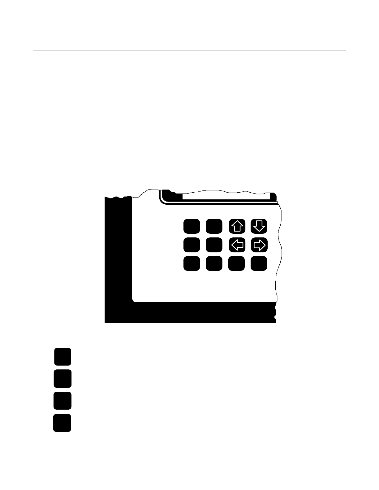
b. Function Keys
The Model 890 has twelve function keys
(Figure 3-2 below). Each key must be
pressed firmly for one second to insure
that the microprocessor recognizes the
keystroke. The definitions for these keys
are as follows:
ZERO F1
ZERO
SPAN
STATUS
SHIFT
Rosemount Analytical
Figure 3-2. Model 890 Keypad
To activate the manual zero
calibration of the analyzer.
To activate the manual span
calibration of the analyzer.
To display the configuration and the
status of alarms and error messages.
Used in conjunction with left and
right or up and down arrows, F1, F2
and ENTER keys. Pressing the
SHIFT key in any
SPAN F2
STATUS MODE SHIFT ENTER
display except Run Mode, Zero
Setting, Span Setting and Status
causes a ↑ to be displayed at the
far right position. Pressing → will
then move the cursor 16 characters
to the right, pressing ← will move
the cursor 16 characters to the left,
and, if a displayed parameter is
being modified, pressing ↑ will
access the highest value allowed for
that parameter and pressing ↓ will
access the lowest value allowed for
that parameter.
3-2 Initial Startup and Calibration Rosemount Analytical Inc. A Division of Emerson Process Management
 Loading...