

Page 1
Rosemount™ 3308 Series Wireless Guided Wave Radar, 3308A
Reference Manual
00809-0100-4308, Rev CB
January 2018
Page 2

Page 3

Reference Manual
00809-0100-4308, Rev CB
Contents
1Section 1: Introduction
2Section 2: Transmitter Overview
Contents
January 2018
1.1 Using this manual . . . . . . . . . . . . . . . . . . . . . . . . . . . . . . . . . . . . . . . . . . . . . . . . . . . . . . . . . . . . . . . . . 1
1.2 Product recycling/disposal. . . . . . . . . . . . . . . . . . . . . . . . . . . . . . . . . . . . . . . . . . . . . . . . . . . . . . . . . . 1
2.1 Theory of operation. . . . . . . . . . . . . . . . . . . . . . . . . . . . . . . . . . . . . . . . . . . . . . . . . . . . . . . . . . . . . . . . 3
2.2 Wireless by Emerson
2.3 Application characteristics. . . . . . . . . . . . . . . . . . . . . . . . . . . . . . . . . . . . . . . . . . . . . . . . . . . . . . . . . . 7
2.3.1 Tank shape. . . . . . . . . . . . . . . . . . . . . . . . . . . . . . . . . . . . . . . . . . . . . . . . . . . . . . . . . . . . . . . . . . 7
2.3.2 In-tank obstructions. . . . . . . . . . . . . . . . . . . . . . . . . . . . . . . . . . . . . . . . . . . . . . . . . . . . . . . . . . 8
2.3.3 Interface level measurement . . . . . . . . . . . . . . . . . . . . . . . . . . . . . . . . . . . . . . . . . . . . . . . . . . 8
2.4 Application examples . . . . . . . . . . . . . . . . . . . . . . . . . . . . . . . . . . . . . . . . . . . . . . . . . . . . . . . . . . . . . . 9
2.5 Components of the transmitter . . . . . . . . . . . . . . . . . . . . . . . . . . . . . . . . . . . . . . . . . . . . . . . . . . . . 10
™
. . . . . . . . . . . . . . . . . . . . . . . . . . . . . . . . . . . . . . . . . . . . . . . . . . . . . . . . . . . . . . 7
2.6 Probe selection guide . . . . . . . . . . . . . . . . . . . . . . . . . . . . . . . . . . . . . . . . . . . . . . . . . . . . . . . . . . . . . 11
3Section 3: Installation
3.1 Safety messages. . . . . . . . . . . . . . . . . . . . . . . . . . . . . . . . . . . . . . . . . . . . . . . . . . . . . . . . . . . . . . . . . . 13
3.2 Installation procedure. . . . . . . . . . . . . . . . . . . . . . . . . . . . . . . . . . . . . . . . . . . . . . . . . . . . . . . . . . . . . 15
3.3 Review mounting considerations . . . . . . . . . . . . . . . . . . . . . . . . . . . . . . . . . . . . . . . . . . . . . . . . . . . 16
3.3.1 Recommended mounting position. . . . . . . . . . . . . . . . . . . . . . . . . . . . . . . . . . . . . . . . . . . . 16
3.3.2 Flange connection on nozzles . . . . . . . . . . . . . . . . . . . . . . . . . . . . . . . . . . . . . . . . . . . . . . . . 18
3.3.3 Installation in non-metallic tanks and open-air applications . . . . . . . . . . . . . . . . . . . . . . 19
3.3.4 Installation in still pipe/chamber . . . . . . . . . . . . . . . . . . . . . . . . . . . . . . . . . . . . . . . . . . . . . . 20
3.4 Review mounting preparations. . . . . . . . . . . . . . . . . . . . . . . . . . . . . . . . . . . . . . . . . . . . . . . . . . . . . 22
3.4.1 Measure tank height . . . . . . . . . . . . . . . . . . . . . . . . . . . . . . . . . . . . . . . . . . . . . . . . . . . . . . . . 22
3.4.2 Shorten the probe . . . . . . . . . . . . . . . . . . . . . . . . . . . . . . . . . . . . . . . . . . . . . . . . . . . . . . . . . . 23
3.4.3 Mount a centering disc for pipe installations . . . . . . . . . . . . . . . . . . . . . . . . . . . . . . . . . . . 28
3.5 Anchor the probe. . . . . . . . . . . . . . . . . . . . . . . . . . . . . . . . . . . . . . . . . . . . . . . . . . . . . . . . . . . . . . . . . 33
3.5.1 Flexible single/twin lead probe . . . . . . . . . . . . . . . . . . . . . . . . . . . . . . . . . . . . . . . . . . . . . . . 33
3.5.2 Rigid single lead probe . . . . . . . . . . . . . . . . . . . . . . . . . . . . . . . . . . . . . . . . . . . . . . . . . . . . . . 34
3.5.3 Coaxial probe . . . . . . . . . . . . . . . . . . . . . . . . . . . . . . . . . . . . . . . . . . . . . . . . . . . . . . . . . . . . . . 35
3.6 Mount device on tank . . . . . . . . . . . . . . . . . . . . . . . . . . . . . . . . . . . . . . . . . . . . . . . . . . . . . . . . . . . . . 36
3.6.1 Threaded tank connection . . . . . . . . . . . . . . . . . . . . . . . . . . . . . . . . . . . . . . . . . . . . . . . . . . . 36
Contents
3.6.2 Tank connection with flange . . . . . . . . . . . . . . . . . . . . . . . . . . . . . . . . . . . . . . . . . . . . . . . . . 38
iii
Page 4

Contents
January 2018
Reference Manual
00809-0100-4308, Rev CB
3.6.3 Tank connection with loose flange (“plate design”) . . . . . . . . . . . . . . . . . . . . . . . . . . . . . 40
3.6.4 Tank connection with Tri Clamp . . . . . . . . . . . . . . . . . . . . . . . . . . . . . . . . . . . . . . . . . . . . . . 41
3.6.5 Segmented probe . . . . . . . . . . . . . . . . . . . . . . . . . . . . . . . . . . . . . . . . . . . . . . . . . . . . . . . . . . 43
3.7 Ground the device . . . . . . . . . . . . . . . . . . . . . . . . . . . . . . . . . . . . . . . . . . . . . . . . . . . . . . . . . . . . . . . . 54
3.8 Install the power module . . . . . . . . . . . . . . . . . . . . . . . . . . . . . . . . . . . . . . . . . . . . . . . . . . . . . . . . . . 55
3.9 Position the antenna . . . . . . . . . . . . . . . . . . . . . . . . . . . . . . . . . . . . . . . . . . . . . . . . . . . . . . . . . . . . . . 55
3.10Utilize the device display . . . . . . . . . . . . . . . . . . . . . . . . . . . . . . . . . . . . . . . . . . . . . . . . . . . . . . . . . . 56
3.10.1Rotate the device display . . . . . . . . . . . . . . . . . . . . . . . . . . . . . . . . . . . . . . . . . . . . . . . . . . . . 56
3.10.2Retrofitting . . . . . . . . . . . . . . . . . . . . . . . . . . . . . . . . . . . . . . . . . . . . . . . . . . . . . . . . . . . . . . . . 56
4Section 4: Configuration
4.1 Overview . . . . . . . . . . . . . . . . . . . . . . . . . . . . . . . . . . . . . . . . . . . . . . . . . . . . . . . . . . . . . . . . . . . . . . . . 57
4.2 Safety messages. . . . . . . . . . . . . . . . . . . . . . . . . . . . . . . . . . . . . . . . . . . . . . . . . . . . . . . . . . . . . . . . . . 58
4.3 Configuration procedure . . . . . . . . . . . . . . . . . . . . . . . . . . . . . . . . . . . . . . . . . . . . . . . . . . . . . . . . . . 59
4.4 System readiness . . . . . . . . . . . . . . . . . . . . . . . . . . . . . . . . . . . . . . . . . . . . . . . . . . . . . . . . . . . . . . . . . 60
4.4.1 Confirm correct device driver. . . . . . . . . . . . . . . . . . . . . . . . . . . . . . . . . . . . . . . . . . . . . . . . . 60
4.5 Get started with your preferred configuration tool. . . . . . . . . . . . . . . . . . . . . . . . . . . . . . . . . . . . 61
4.5.1 AMS Wireless Configurator (version 12.0 or later is required) . . . . . . . . . . . . . . . . . . . . . 61
4.5.2 Field Communicator . . . . . . . . . . . . . . . . . . . . . . . . . . . . . . . . . . . . . . . . . . . . . . . . . . . . . . . . 63
4.6 Join device to wireless network . . . . . . . . . . . . . . . . . . . . . . . . . . . . . . . . . . . . . . . . . . . . . . . . . . . . . 64
4.6.1 Power up the wireless device . . . . . . . . . . . . . . . . . . . . . . . . . . . . . . . . . . . . . . . . . . . . . . . . . 64
4.6.2 Connect to device. . . . . . . . . . . . . . . . . . . . . . . . . . . . . . . . . . . . . . . . . . . . . . . . . . . . . . . . . . . 66
4.6.3 Configure update rate . . . . . . . . . . . . . . . . . . . . . . . . . . . . . . . . . . . . . . . . . . . . . . . . . . . . . . . 67
4.6.4 Obtain network ID and join key . . . . . . . . . . . . . . . . . . . . . . . . . . . . . . . . . . . . . . . . . . . . . . . 67
4.6.5 Enter network ID and join key . . . . . . . . . . . . . . . . . . . . . . . . . . . . . . . . . . . . . . . . . . . . . . . . 68
4.6.6 Verify device joins network. . . . . . . . . . . . . . . . . . . . . . . . . . . . . . . . . . . . . . . . . . . . . . . . . . . 68
4.7 Configure device using guided setup. . . . . . . . . . . . . . . . . . . . . . . . . . . . . . . . . . . . . . . . . . . . . . . . 72
4.7.1 Connect to device. . . . . . . . . . . . . . . . . . . . . . . . . . . . . . . . . . . . . . . . . . . . . . . . . . . . . . . . . . . 72
4.7.2 Basic setup . . . . . . . . . . . . . . . . . . . . . . . . . . . . . . . . . . . . . . . . . . . . . . . . . . . . . . . . . . . . . . . . . 73
4.7.3 Optional setup . . . . . . . . . . . . . . . . . . . . . . . . . . . . . . . . . . . . . . . . . . . . . . . . . . . . . . . . . . . . . 73
4.8 Verify level. . . . . . . . . . . . . . . . . . . . . . . . . . . . . . . . . . . . . . . . . . . . . . . . . . . . . . . . . . . . . . . . . . . . . . . 74
5Section 5: Operation
5.1 Safety messages. . . . . . . . . . . . . . . . . . . . . . . . . . . . . . . . . . . . . . . . . . . . . . . . . . . . . . . . . . . . . . . . . . 75
5.2 Device display screen messages . . . . . . . . . . . . . . . . . . . . . . . . . . . . . . . . . . . . . . . . . . . . . . . . . . . . 77
5.2.1 Variable screens . . . . . . . . . . . . . . . . . . . . . . . . . . . . . . . . . . . . . . . . . . . . . . . . . . . . . . . . . . . . 77
5.2.2 Diagnostic button screen sequence . . . . . . . . . . . . . . . . . . . . . . . . . . . . . . . . . . . . . . . . . . . 78
5.3 View measurement values. . . . . . . . . . . . . . . . . . . . . . . . . . . . . . . . . . . . . . . . . . . . . . . . . . . . . . . . . 80
iv
Contents
Page 5

Reference Manual
00809-0100-4308, Rev CB
6Section 6: Service and Troubleshooting
Contents
January 2018
5.3.1 View current measurement values . . . . . . . . . . . . . . . . . . . . . . . . . . . . . . . . . . . . . . . . . . . . 80
5.3.2 View trends . . . . . . . . . . . . . . . . . . . . . . . . . . . . . . . . . . . . . . . . . . . . . . . . . . . . . . . . . . . . . . . . 80
5.3.3 Interpret measurement status bars . . . . . . . . . . . . . . . . . . . . . . . . . . . . . . . . . . . . . . . . . . . 80
5.4 Check device status. . . . . . . . . . . . . . . . . . . . . . . . . . . . . . . . . . . . . . . . . . . . . . . . . . . . . . . . . . . . . . . 81
6.1 Safety messages. . . . . . . . . . . . . . . . . . . . . . . . . . . . . . . . . . . . . . . . . . . . . . . . . . . . . . . . . . . . . . . . . . 83
6.2 Alert messages . . . . . . . . . . . . . . . . . . . . . . . . . . . . . . . . . . . . . . . . . . . . . . . . . . . . . . . . . . . . . . . . . . . 84
6.2.1 Device display alerts. . . . . . . . . . . . . . . . . . . . . . . . . . . . . . . . . . . . . . . . . . . . . . . . . . . . . . . . . 84
6.2.2 Alert messages in AMS Wireless Configurator and Field Communicator. . . . . . . . . . . . 86
6.3 Troubleshooting guide . . . . . . . . . . . . . . . . . . . . . . . . . . . . . . . . . . . . . . . . . . . . . . . . . . . . . . . . . . . . 90
6.3.1 Incorrect level readings . . . . . . . . . . . . . . . . . . . . . . . . . . . . . . . . . . . . . . . . . . . . . . . . . . . . . . 90
6.3.2 Incorrect or missing interface level reading . . . . . . . . . . . . . . . . . . . . . . . . . . . . . . . . . . . . 91
6.3.3 Power module troubleshooting. . . . . . . . . . . . . . . . . . . . . . . . . . . . . . . . . . . . . . . . . . . . . . . 92
6.3.4 Device display troubleshooting . . . . . . . . . . . . . . . . . . . . . . . . . . . . . . . . . . . . . . . . . . . . . . . 92
6.3.5 Wireless network troubleshooting . . . . . . . . . . . . . . . . . . . . . . . . . . . . . . . . . . . . . . . . . . . . 92
6.4 Service and troubleshooting tools . . . . . . . . . . . . . . . . . . . . . . . . . . . . . . . . . . . . . . . . . . . . . . . . . . 93
6.4.1 Reading the echo curve . . . . . . . . . . . . . . . . . . . . . . . . . . . . . . . . . . . . . . . . . . . . . . . . . . . . . . 93
6.4.2 Adjusting thresholds . . . . . . . . . . . . . . . . . . . . . . . . . . . . . . . . . . . . . . . . . . . . . . . . . . . . . . . . 94
6.4.3 Viewing measurement history . . . . . . . . . . . . . . . . . . . . . . . . . . . . . . . . . . . . . . . . . . . . . . . . 98
6.4.4 Reviewing network join status and details. . . . . . . . . . . . . . . . . . . . . . . . . . . . . . . . . . . . . . 99
6.4.5 Locating the device . . . . . . . . . . . . . . . . . . . . . . . . . . . . . . . . . . . . . . . . . . . . . . . . . . . . . . . . . 99
6.4.6 Using the simulation mode. . . . . . . . . . . . . . . . . . . . . . . . . . . . . . . . . . . . . . . . . . . . . . . . . . 100
6.4.7 Using the verification method . . . . . . . . . . . . . . . . . . . . . . . . . . . . . . . . . . . . . . . . . . . . . . . 100
6.5 Application challenges . . . . . . . . . . . . . . . . . . . . . . . . . . . . . . . . . . . . . . . . . . . . . . . . . . . . . . . . . . . 100
6.5.1 Resolving thin oil layers . . . . . . . . . . . . . . . . . . . . . . . . . . . . . . . . . . . . . . . . . . . . . . . . . . . . . 100
6.5.2 Handling disturbances at the top of the tank . . . . . . . . . . . . . . . . . . . . . . . . . . . . . . . . . . 102
6.5.3 Interface measurements with fully submerged probes. . . . . . . . . . . . . . . . . . . . . . . . . . 105
6.5.4 Noise or weak surface echoes . . . . . . . . . . . . . . . . . . . . . . . . . . . . . . . . . . . . . . . . . . . . . . . 106
6.6 Power module replacement . . . . . . . . . . . . . . . . . . . . . . . . . . . . . . . . . . . . . . . . . . . . . . . . . . . . . . 106
6.7 Transmitter head replacement . . . . . . . . . . . . . . . . . . . . . . . . . . . . . . . . . . . . . . . . . . . . . . . . . . . . 108
6.8 Probe replacement . . . . . . . . . . . . . . . . . . . . . . . . . . . . . . . . . . . . . . . . . . . . . . . . . . . . . . . . . . . . . . 109
6.9 Service support. . . . . . . . . . . . . . . . . . . . . . . . . . . . . . . . . . . . . . . . . . . . . . . . . . . . . . . . . . . . . . . . . . 110
Contents
AAppendix A: Specifications and Reference Data
A.1 Performance specifications . . . . . . . . . . . . . . . . . . . . . . . . . . . . . . . . . . . . . . . . . . . . . . . . . . . . . . . 111
A.1.1 General . . . . . . . . . . . . . . . . . . . . . . . . . . . . . . . . . . . . . . . . . . . . . . . . . . . . . . . . . . . . . . . . . . . 111
A.1.2 Environment . . . . . . . . . . . . . . . . . . . . . . . . . . . . . . . . . . . . . . . . . . . . . . . . . . . . . . . . . . . . . . 111
v
Page 6

Contents
January 2018
Reference Manual
00809-0100-4308, Rev CB
A.1.3 Interface measuring range . . . . . . . . . . . . . . . . . . . . . . . . . . . . . . . . . . . . . . . . . . . . . . . . . . 112
A.1.4 Accuracy over measuring range . . . . . . . . . . . . . . . . . . . . . . . . . . . . . . . . . . . . . . . . . . . . . 114
A.2 Functional specifications . . . . . . . . . . . . . . . . . . . . . . . . . . . . . . . . . . . . . . . . . . . . . . . . . . . . . . . . . 116
A.2.1 General . . . . . . . . . . . . . . . . . . . . . . . . . . . . . . . . . . . . . . . . . . . . . . . . . . . . . . . . . . . . . . . . . . . 116
A.2.2 Wireless . . . . . . . . . . . . . . . . . . . . . . . . . . . . . . . . . . . . . . . . . . . . . . . . . . . . . . . . . . . . . . . . . . 116
A.2.3 Display and configuration. . . . . . . . . . . . . . . . . . . . . . . . . . . . . . . . . . . . . . . . . . . . . . . . . . . 117
A.2.4 Temperature limits. . . . . . . . . . . . . . . . . . . . . . . . . . . . . . . . . . . . . . . . . . . . . . . . . . . . . . . . . 117
A.2.5 Process temperature and pressure rating . . . . . . . . . . . . . . . . . . . . . . . . . . . . . . . . . . . . . 118
A.2.6 Flange rating . . . . . . . . . . . . . . . . . . . . . . . . . . . . . . . . . . . . . . . . . . . . . . . . . . . . . . . . . . . . . . 118
A.2.7 Plate design . . . . . . . . . . . . . . . . . . . . . . . . . . . . . . . . . . . . . . . . . . . . . . . . . . . . . . . . . . . . . . . 118
A.2.8 Interface measurements. . . . . . . . . . . . . . . . . . . . . . . . . . . . . . . . . . . . . . . . . . . . . . . . . . . . 119
A.2.9 Conditions used for flange strength calculations. . . . . . . . . . . . . . . . . . . . . . . . . . . . . . . 120
A.3 Physical specifications. . . . . . . . . . . . . . . . . . . . . . . . . . . . . . . . . . . . . . . . . . . . . . . . . . . . . . . . . . . . 121
A.3.1 Material selection . . . . . . . . . . . . . . . . . . . . . . . . . . . . . . . . . . . . . . . . . . . . . . . . . . . . . . . . . . 121
A.3.2 Tank connection. . . . . . . . . . . . . . . . . . . . . . . . . . . . . . . . . . . . . . . . . . . . . . . . . . . . . . . . . . . 121
A.3.3 Housing and enclosure . . . . . . . . . . . . . . . . . . . . . . . . . . . . . . . . . . . . . . . . . . . . . . . . . . . . . 121
A.3.4 Flange dimensions . . . . . . . . . . . . . . . . . . . . . . . . . . . . . . . . . . . . . . . . . . . . . . . . . . . . . . . . . 121
A.3.5 Probes. . . . . . . . . . . . . . . . . . . . . . . . . . . . . . . . . . . . . . . . . . . . . . . . . . . . . . . . . . . . . . . . . . . . 121
A.3.6 Material exposed to tank atmosphere . . . . . . . . . . . . . . . . . . . . . . . . . . . . . . . . . . . . . . . . 122
A.3.7 Weight . . . . . . . . . . . . . . . . . . . . . . . . . . . . . . . . . . . . . . . . . . . . . . . . . . . . . . . . . . . . . . . . . . . 122
A.3.8 End weight and anchoring options . . . . . . . . . . . . . . . . . . . . . . . . . . . . . . . . . . . . . . . . . . . 123
A.3.9 Engineered solutions . . . . . . . . . . . . . . . . . . . . . . . . . . . . . . . . . . . . . . . . . . . . . . . . . . . . . . . 123
A.4 Ordering information . . . . . . . . . . . . . . . . . . . . . . . . . . . . . . . . . . . . . . . . . . . . . . . . . . . . . . . . . . . . 124
A.5 Spare parts and accessories. . . . . . . . . . . . . . . . . . . . . . . . . . . . . . . . . . . . . . . . . . . . . . . . . . . . . . . 130
A.6 Dimensional drawings . . . . . . . . . . . . . . . . . . . . . . . . . . . . . . . . . . . . . . . . . . . . . . . . . . . . . . . . . . . 139
BAppendix B: Product Certifications
B.1 Safety messages. . . . . . . . . . . . . . . . . . . . . . . . . . . . . . . . . . . . . . . . . . . . . . . . . . . . . . . . . . . . . . . . . 147
B.2 European Union directive information. . . . . . . . . . . . . . . . . . . . . . . . . . . . . . . . . . . . . . . . . . . . . . 148
B.3 Telecommunication compliance . . . . . . . . . . . . . . . . . . . . . . . . . . . . . . . . . . . . . . . . . . . . . . . . . . 148
B.4 FCC and IC . . . . . . . . . . . . . . . . . . . . . . . . . . . . . . . . . . . . . . . . . . . . . . . . . . . . . . . . . . . . . . . . . . . . . . 148
B.5 Ordinary location certification for FM approvals . . . . . . . . . . . . . . . . . . . . . . . . . . . . . . . . . . . . . 148
B.6 Hazardous locations certificates. . . . . . . . . . . . . . . . . . . . . . . . . . . . . . . . . . . . . . . . . . . . . . . . . . . 148
B.6.1 U.S.A. . . . . . . . . . . . . . . . . . . . . . . . . . . . . . . . . . . . . . . . . . . . . . . . . . . . . . . . . . . . . . . . . . . . . 148
B.6.2 Canada . . . . . . . . . . . . . . . . . . . . . . . . . . . . . . . . . . . . . . . . . . . . . . . . . . . . . . . . . . . . . . . . . . . 149
B.6.3 Europe . . . . . . . . . . . . . . . . . . . . . . . . . . . . . . . . . . . . . . . . . . . . . . . . . . . . . . . . . . . . . . . . . . . 149
B.6.4 International . . . . . . . . . . . . . . . . . . . . . . . . . . . . . . . . . . . . . . . . . . . . . . . . . . . . . . . . . . . . . . 149
B.6.5 Brazil . . . . . . . . . . . . . . . . . . . . . . . . . . . . . . . . . . . . . . . . . . . . . . . . . . . . . . . . . . . . . . . . . . . . . 149
vi
Contents
Page 7

Reference Manual
00809-0100-4308, Rev CB
CAppendix C: High Gain Remote Antenna Option
Contents
January 2018
B.6.6 China . . . . . . . . . . . . . . . . . . . . . . . . . . . . . . . . . . . . . . . . . . . . . . . . . . . . . . . . . . . . . . . . . . . . . 150
B.6.7 Japan . . . . . . . . . . . . . . . . . . . . . . . . . . . . . . . . . . . . . . . . . . . . . . . . . . . . . . . . . . . . . . . . . . . . . 150
B.6.8 EAC – Belarus, Kazakhstan, Russia. . . . . . . . . . . . . . . . . . . . . . . . . . . . . . . . . . . . . . . . . . . . 150
B.6.9 Taiwan . . . . . . . . . . . . . . . . . . . . . . . . . . . . . . . . . . . . . . . . . . . . . . . . . . . . . . . . . . . . . . . . . . . 150
B.7 Other certifications . . . . . . . . . . . . . . . . . . . . . . . . . . . . . . . . . . . . . . . . . . . . . . . . . . . . . . . . . . . . . . 150
B.8 Approval drawings. . . . . . . . . . . . . . . . . . . . . . . . . . . . . . . . . . . . . . . . . . . . . . . . . . . . . . . . . . . . . . . 150
C.1 Safety messages. . . . . . . . . . . . . . . . . . . . . . . . . . . . . . . . . . . . . . . . . . . . . . . . . . . . . . . . . . . . . . . . . 153
C.2 Functional and physical specifications. . . . . . . . . . . . . . . . . . . . . . . . . . . . . . . . . . . . . . . . . . . . . . 154
C.2.1 General . . . . . . . . . . . . . . . . . . . . . . . . . . . . . . . . . . . . . . . . . . . . . . . . . . . . . . . . . . . . . . . . . . . 154
C.2.2 Wireless . . . . . . . . . . . . . . . . . . . . . . . . . . . . . . . . . . . . . . . . . . . . . . . . . . . . . . . . . . . . . . . . . . 154
C.2.3 Coaxial cable . . . . . . . . . . . . . . . . . . . . . . . . . . . . . . . . . . . . . . . . . . . . . . . . . . . . . . . . . . . . . . 154
C.2.4 RF Lightning Arrestor . . . . . . . . . . . . . . . . . . . . . . . . . . . . . . . . . . . . . . . . . . . . . . . . . . . . . . . 154
C.2.5 Mounting bracket. . . . . . . . . . . . . . . . . . . . . . . . . . . . . . . . . . . . . . . . . . . . . . . . . . . . . . . . . . 154
C.2.6 Antenna . . . . . . . . . . . . . . . . . . . . . . . . . . . . . . . . . . . . . . . . . . . . . . . . . . . . . . . . . . . . . . . . . . 154
C.3 Review installation considerations . . . . . . . . . . . . . . . . . . . . . . . . . . . . . . . . . . . . . . . . . . . . . . . . . 154
C.3.1 Antenna mounting. . . . . . . . . . . . . . . . . . . . . . . . . . . . . . . . . . . . . . . . . . . . . . . . . . . . . . . . . 154
C.3.2 Antenna height . . . . . . . . . . . . . . . . . . . . . . . . . . . . . . . . . . . . . . . . . . . . . . . . . . . . . . . . . . . . 154
C.3.3 Affix coaxial cable . . . . . . . . . . . . . . . . . . . . . . . . . . . . . . . . . . . . . . . . . . . . . . . . . . . . . . . . . . 155
C.3.4 Install coaxial drip loop . . . . . . . . . . . . . . . . . . . . . . . . . . . . . . . . . . . . . . . . . . . . . . . . . . . . . 155
C.3.5 Apply coaxial sealant moisture protection . . . . . . . . . . . . . . . . . . . . . . . . . . . . . . . . . . . . 155
C.4 Transient/lightning considerations . . . . . . . . . . . . . . . . . . . . . . . . . . . . . . . . . . . . . . . . . . . . . . . . 155
C.4.1 Gateway transient protection . . . . . . . . . . . . . . . . . . . . . . . . . . . . . . . . . . . . . . . . . . . . . . . 155
C.4.2 RF lightning arrestor ground connection. . . . . . . . . . . . . . . . . . . . . . . . . . . . . . . . . . . . . . 155
C.5 Install the high gain remote antenna. . . . . . . . . . . . . . . . . . . . . . . . . . . . . . . . . . . . . . . . . . . . . . . 156
DAppendix D: Configuration Parameters
D.1 Safety messages. . . . . . . . . . . . . . . . . . . . . . . . . . . . . . . . . . . . . . . . . . . . . . . . . . . . . . . . . . . . . . . . . 159
D.2 Menu overview of the Device Descriptor (DD) . . . . . . . . . . . . . . . . . . . . . . . . . . . . . . . . . . . . . . . 160
D.3 Configuration parameters . . . . . . . . . . . . . . . . . . . . . . . . . . . . . . . . . . . . . . . . . . . . . . . . . . . . . . . . 161
D.3.1 Guided setup. . . . . . . . . . . . . . . . . . . . . . . . . . . . . . . . . . . . . . . . . . . . . . . . . . . . . . . . . . . . . . 161
D.3.2 Manual setup - Device . . . . . . . . . . . . . . . . . . . . . . . . . . . . . . . . . . . . . . . . . . . . . . . . . . . . . . 164
D.3.3 Manual setup - Level . . . . . . . . . . . . . . . . . . . . . . . . . . . . . . . . . . . . . . . . . . . . . . . . . . . . . . . 168
Contents
D.3.4 Alert setup . . . . . . . . . . . . . . . . . . . . . . . . . . . . . . . . . . . . . . . . . . . . . . . . . . . . . . . . . . . . . . . . 172
D.3.5 Echo Tuning. . . . . . . . . . . . . . . . . . . . . . . . . . . . . . . . . . . . . . . . . . . . . . . . . . . . . . . . . . . . . . . 176
EAppendix E: Alert Message Mapping
E.1 Alert messages and descriptions. . . . . . . . . . . . . . . . . . . . . . . . . . . . . . . . . . . . . . . . . . . . . . . . . . . 179
vii
Page 8

Contents
January 2018
Reference Manual
00809-0100-4308, Rev CB
viii
Contents
Page 9

Reference Manual
00809-0100-4308, Rev CB
Rosemount™ 3308 Series Wireless
Guided Wave Radar Level Transmitter
NOTICE
Read this manual before working with the product. For personal and system safety, and for optimum
product performance, make sure you thoroughly understand the contents before installing, using, or
maintaining this product.
For technical assistance, contacts are listed below:
Customer Central
Technical support, quoting, and order-related questions.
United States - 1-800-999-9307 (7:00 am to 7:00 pm CST)
Asia Pacific- 65 777 8211
Europe / Middle East / Africa - 49 (8153) 9390
North American Response Center
Equipment service needs.
1-800-654-7768 (24 hours a day — includes Canada)
Outside of these areas, contact your local Emerson
Power Module Considerations.
Each Power Module contains two "C" size primary lithium/thionyl chloride batteries. Each battery
contains approximately 2.5 grams of lithium, for a total of 5 grams in each pack. Under normal
conditions, the battery materials are self-contained and are not reactive as long as the batteries and the
pack integrity are maintained. Care should be taken to prevent thermal, electrical or mechanical
damage. Contacts should be protected to prevent premature discharge.
Battery hazards remain when cells are discharged.
Power modules should be stored in a clean and dry area. For maximum battery life, storage temperature
should not exceed 30 °C.
The Power Module may be replaced in a hazardous area. The Power Module has surface resistivity
greater than one gigaohm and must be properly installed in the wireless device enclosure. Care must be
taken during transportation to and from the point of installation to prevent electrostatic charge
build-up.
Shipping considerations for wireless products.
The unit was shipped to you without the Power Module installed. Please remove the Power Module prior
to shipping the unit.
Each Power Module contains two "C" size primary lithium/thionyl chloride batteries. Primary lithium
batteries (charged or discharged) are regulated during transportation by the U.S. Department of
Transportation. They are also covered by IATA (International Air Transport Association), ICAO
(International Civil Aviation Organization), and ARD (European Ground Transportation of Dangerous
Goods). It is the responsibility of the shipper to ensure compliance with these or any other local
requirements. Consult current regulations and requirements before shipping.
™
representative.
Title Page
January 2018
Title Page
ix
Page 10

Title Page
January 2018
Reference Manual
00809-0100-4308, Rev CB
Explosions could result in death or serious injury.
Verify that the operating environment of the gauge is consistent with the appropriate hazardous
locations certifications.
Installation of device in an explosive environment must be in accordance with appropriate local,
national and international standards, codes, and practices.
Ensure device is installed in accordance with intrinsically safe or non-incendive field practices.
Electrical shock can result in death or serious injury.
Ground device on non-metallic tanks (e.g. fiberglass tanks) to prevent electrostatic charge build-up.
Single lead probes are sensitive for strong electromagnetic fields and therefore not suitable for
non-metallic tanks.
Care must be taken during transportation of power module to prevent electrostatic charge build-up.
Device must be installed to ensure a minimum antenna separation distance of 8 in. (20 cm) from all
persons.
Probes covered with plastic and/or with plastic discs may generate an ignition-capable level of
electrostatic charge under certain extreme conditions. Therefore, when the probe is used in a
potentially explosive atmosphere, appropriate measures must be taken to prevent electrostatic
discharge.
Process leaks could result in death or serious injury.
Only qualified personnel should install the equipment.
Install transmitter prior to process start-up.
Install and tighten process connectors before applying pressure.
Handle the transmitter carefully.
Do not remove the transmitter while in operation.
If the process seal is damaged, gas could escape from the tank when removing the transmitter head
from the probe.
Failure to follow safe installation guidelines could result in death or serious injury.
Verify that the operating environment of the gauge is consistent with the appropriate hazardous
locations certifications.
Make sure the transmitter is installed by qualified personnel and in accordance with applicable code
of practice.
Use the equipment only as specified in this manual. Failure to do so may impair the protection
provided by the equipment.
x
Title Page
Page 11
Reference Manual
00809-0100-4308, Rev CB
Electronic boards are electrostatically sensitive. Failure to observe proper handling precautions for
static-sensitive components can result in damage to the electronic components. Do not remove the
electronic boards from the Rosemount 3308 Series Transmitter.
To ensure long life for your radar transmitter, and to comply with hazardous location installation
requirements, tighten covers on both sides of the electronics housing.
Any substitution of non-recognized parts may jeopardize safety. Repair, e.g. substitution of components
etc., may also jeopardize safety and is under no circumstances allowed.
This device complies with Part 15 of the FCC Rules. Operation is subject to the following conditions: This
device may not cause harmful interference. This device must accept any interference received, including
interference that may cause undesired operation. This device must be installed to ensure a minimum
antenna separation distance of 20 cm (8 in.) from all persons.
The products described in this document are NOT designed for nuclear-qualified applications.
Using non-nuclear qualified products in applications that require nuclear-qualified hardware or
products may cause inaccurate readings.
For information on Rosemount nuclear-qualified products, contact your local Emerson Sales
Representative.
Individuals who handle products exposed to a hazardous substance can avoid injury if they are informed
of and understand the hazard. If the product being returned was exposed to a hazardous substance as
defined by Occupational Safety and Health Administration (OSHA), a copy of the required Safety Data
Sheet (SDS) for each hazardous substance identified must be included with the returned goods.
Use caution when handling the Power Module. The Power Module may be damaged if dropped from
heights in excess of 20 ft. (6 m).
Changes or modifications to the equipment not expressly approved by Rosemount Inc. could void the
user’s authority to operate the equipment.
Title Page
January 2018
Title Page
xi
Page 12

Title Page
January 2018
Reference Manual
00809-0100-4308, Rev CB
xii
Title Page
Page 13

Reference Manual
00809-0100-4308, Rev CB
Section 1 Introduction
1.1 Using this manual
The sections in this manual provide information on installing, configuring, operating, and maintaining
the Rosemount
Section 2: Transmitter Overview provides an introduction to theory of operation and description of the
transmitter. Information on applications and a probe selection guide are also included.
Section 3: Installation contains mechanical and electrical installation instructions.
Section 4: Configuration provides instructions on how to configure and make the transmitter join the
wireless network.
Section 5: Operation contains operation techniques such as viewing measurement data and display
functionality.
Section 6: Service and Troubleshooting provides troubleshooting techniques for the most common
operating problems, as well as diagnostic and error messages, and service instructions.
™
3308 Series Transmitter. The sections are organized as follows:
Introduction
January 2018
Appendix A: Specifications and Reference Data supplies reference and specification data, as well as ordering
information.
Appendix B: Product Certifications contains hazardous locations certifications and approval drawings.
Appendix C: High Gain Remote Antenna Option contains specification and installation information of the high
gain remote antenna option.
Appendix D: Configuration Parameters provides a menu overview for the Device Descriptor in AMS Wireless
Configurator and the Field Communicator. Description of the configuration parameters is also included.
Appendix E: Alert Message Mapping outlines the most important alerts in the HART
Additional Status Field for Rosemount 3308 Series.
1.2 Product recycling/disposal
Recycling of equipment and packaging should be taken into consideration and disposed in accordance
with local and national legislation/regulations.
®
command 48
Introduction
1
Page 14

Introduction
January 2018
Reference Manual
00809-0100-4308, Rev CB
2
Introduction
Page 15
Reference Manual
Time
A
Signal
Amplitude
H
F
E
G
B
D
C
I
00809-0100-4308, Rev CB
Section 2 Transmitter Overview
Theory of operation . . . . . . . . . . . . . . . . . . . . . . . . . . . . . . . . . . . . . . . . . . . . . . . . . . . . . . . . . . . . . . . . . . . .page 3
Wireless by Emerson™ . . . . . . . . . . . . . . . . . . . . . . . . . . . . . . . . . . . . . . . . . . . . . . . . . . . . . . . . . . . . . . . . .page 7
Application characteristics . . . . . . . . . . . . . . . . . . . . . . . . . . . . . . . . . . . . . . . . . . . . . . . . . . . . . . . . . . . . . .page 7
Application examples . . . . . . . . . . . . . . . . . . . . . . . . . . . . . . . . . . . . . . . . . . . . . . . . . . . . . . . . . . . . . . . . . .page 9
Components of the transmitter . . . . . . . . . . . . . . . . . . . . . . . . . . . . . . . . . . . . . . . . . . . . . . . . . . . . . . . . page 10
Probe selection guide . . . . . . . . . . . . . . . . . . . . . . . . . . . . . . . . . . . . . . . . . . . . . . . . . . . . . . . . . . . . . . . . page 11
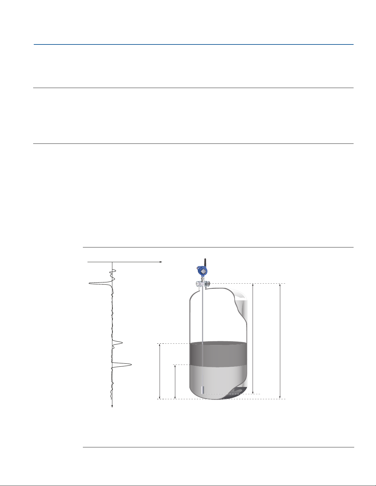
2.1 Theory of operation
The Rosemount™ 3308 Series is the first true wireless level transmitter that is based on the Time Domain
Reflectometry (TDR) principle. Low power nano-second-pulses are guided along a probe submerged in
the process media. When a pulse reaches the surface of the material it is measuring, part of the energy is
reflected back to the transmitter, and the time difference between the generated and reflected pulse is
converted into a distance from which the total level or interface level is calculated (see Figure 2-1). See
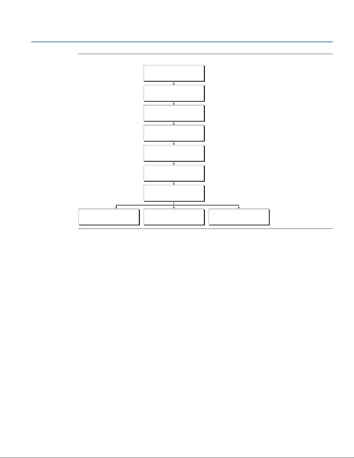
Figure 2-2 for a schematic overview of the signal processing.
Transmitter Overview
January 2018
The reflectivity of the product is a key parameter for measurement performance. A high dielectric
constant of the media gives better reflection and a longer measuring range.
Figure 2-1. Guided Wave Radar Operating Principle
Tra nsm itter O verview
A. Reference Peak F. Upper Reference Point
B. Product Surface Peak G. Probe Length
C. Product Level H. Tan k Heigh t
D. Interface Peak I. Zero Reference Point
E. Interface Level
3
Page 16
Transmitter Overview
Microwave module
A/D converter
Peak search
Peak interpolation
Echo identifier
Distance filtering
Variable calculation
Aout handler LCD handler HART
®
January 2018
Figure 2-2. Flowchart of the Signal Processing
Reference Manual
00809-0100-4308, Rev CB
Reference peak
This peak is caused by the transition between transmitter and the tank vapor space or air. It is used by the
transmitter as a starting reference point for distance to the level surface.
Product surface peak
This peak indicates the product level and is caused by a reflection from the product surface.
Interface peak
This peak indicates the interface level. The peak is caused by reflection from the interface between an
upper product and a bottom product with a relatively high dielectric constant. This peak is identified
when the Measurement Mode is set to Product Level and Interface Level or Interface Level with
Submerged Probe.
Probe end peak
It is caused by reflection from the probe end. If the probe is grounded, the peak will be positive. If the
probe end is submerged in a high dielectric media, such as water, it will not be visible.
Upper reference point
The Upper Reference Point is located at the underside of the threaded adapter, transmitter flange, or Tri
Clamp, as illustrated in Figure 2-3 on page 5.
4
Tra nsmitter O verview
Page 17
Reference Manual
NPT BSPP (G) FlangeATri Clamp
B
00809-0100-4308, Rev CB
Figure 2-3. Upper Reference Point
A. Upper Reference Point
B. Probe Length
Transmitter Overview
January 2018
Zero reference point
The Zero Reference Point is selected by the user and is usually located close to or at the bottom of the
tank. The Zero Reference Point can be set to any position in the tank by adjusting the Tank Height.
Tank height
The Tank Height is the distance from the Upper Reference Point to the Zero Reference Point. The
transmitter measures the distance to the product surface and subtracts this value from the Tank Height
to determine the level.
Probe length
The probe length is the distance between the Upper Reference Point and the end of the probe. If a
weight is used at the end of the probe it shall be included.
Blind zones
The measuring range depends on probe type, dielectric constant of the product and installation
environment, and is limited by the Blind Zones at the very top and bottom of the probe. In the Blind
Zones, the accuracy exceeds ±1.18 in. (30 mm), and measurements may not be possible. Measurements
close to the Blind Zones will have reduced accuracy.
Figure 2-4 illustrates how the measuring range is related to the Blind Zones and the areas with reduced
accuracy. Values for different probe types and dielectric constants are presented in section “Ac cu ra cy
over measuring range” on page 114.
Tra nsm itter O verview
5
Page 18
Transmitter Overview
A
E
B
D
C
January 2018
Figure 2-4. Blind Zones
Reference Manual
00809-0100-4308, Rev CB
A. Upper Blind Zone D. Reduced Accuracy
B. Reduced Accuracy E. Lower Blind Zone
C. Recommended Measuring Range
Note
Measurements may not be possible in the Blind Zones, and measurements close to the Blind Zones will
have reduced accuracy. Therefore, the alarm points should be configured outside these zones.
6
Tra nsmitter O verview
Page 19
Reference Manual
00809-0100-4308, Rev CB
Transmitter Overview
January 2018
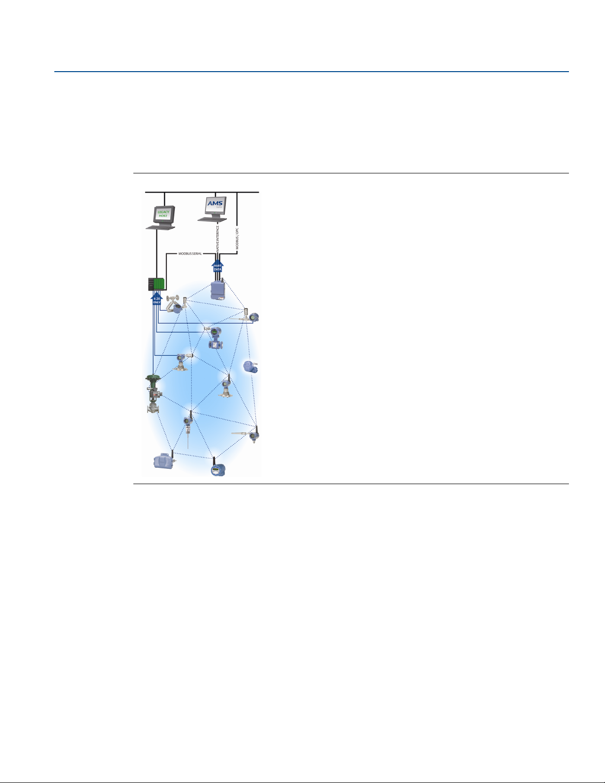
2.2 Wireless by Emerson
The Emerson Wireless network is a self-organizing solution. Wireless field instruments send data to a
Gateway, directly or routed through any of the wireless devices in the network, as illustrated in
Figure 2-5. Multiple communication paths are managed and analyzed in parallel to assure optimal
communication and sustained network reliability even if obstructions are introduced.
Figure 2-5. Emerson Wireless Network
™
Gateways interface with existing host systems using industry standard protocols, and native integration
into DeltaV
Interference from other radios, Wi-Fi
Hopping and Direct Sequence Spread Spectrum (DSSS). Also, a layered security implementing industry
standard Encryption, Authentication, Verification, Anti-Jamming, and Key Management ensures that
data transmissions are secure and received only by the Gateway.
™
and Ovation™ is transparent and seamless.
®
, and EMC sources is avoided through Time Synchronized Channel
2.3 Application characteristics
2.3.1 Tank shape
The guided wave radar transmitter is insensitive to the tank shape. Since the radar signal travels along a
probe, the shape of the tank bottom has no effect on the measurement performance. The transmitter
handles flat or dish-bottom tanks equally well.
Tra nsm itter O verview
7
Page 20
Transmitter Overview
A
B
B
January 2018
2.3.2 In-tank obstructions
The Rosemount 3308 Series Transmitter is relatively insensitive to objects in the tank since the radar
signal is transmitted along a probe.
Avoid physical contact between probes and agitators as well as applications with strong fluid movement
unless the probe is anchored. If the probe can move within 1 ft. (30 cm) away from any object, such as an
agitator, during operation then probe tie-down is recommended.
In order to stabilize the probe for side forces, you have the option to either hang a weight at the probe
end (flexible probes only) or fix/guide the probe to the tank bottom.
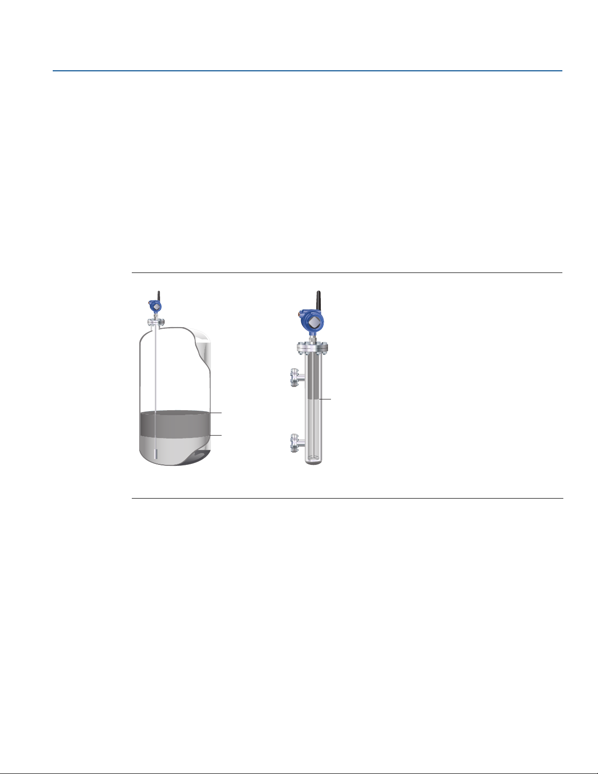
2.3.3 Interface level measurement
Rosemount 3308 Series Transmitter is well suited for measuring the interface of oil and water, or other
liquids with significant dielectric differences.
Figure 2-6. Interface Level Measurement
Reference Manual
00809-0100-4308, Rev CB
A. Product Level
B. Interface Level
All probes can be used for measuring interfaces. Single probes are the preferred choice in almost all
applications but depending on the application and installation geometries a coaxial probe or a flexible
twin probe may be a better fit.
For measuring the interface level, the transmitter uses the residual wave of the first reflection. Part of the
wave, which was not reflected at the upper product surface, continues until it is reflected at the lower
product surface. The speed of this wave depends fully on the dielectric constant of the upper product.
The maximum allowable upper product thickness/measuring range is primarily determined by the
dielectric constants of the two liquids. Target applications include interfaces between oil/oil-like and
water/water-like liquids. For such applications the upper product dielectric constant is low (<3) and the
lower product dielectric constant is high (>20). Refer to “Interface measurements” on page 119 for
further interface application guidelines.
Emulsion layers
Sometimes there is an emulsion layer (mix of the products) between the two products which, depending
on its characteristics, will affect interface measurements. Please consult factory for guidelines on how to
handle emulsion layers.
8
Tra nsmitter O verview
Page 21
Reference Manual
Oil
Oil
Water
00809-0100-4308, Rev CB
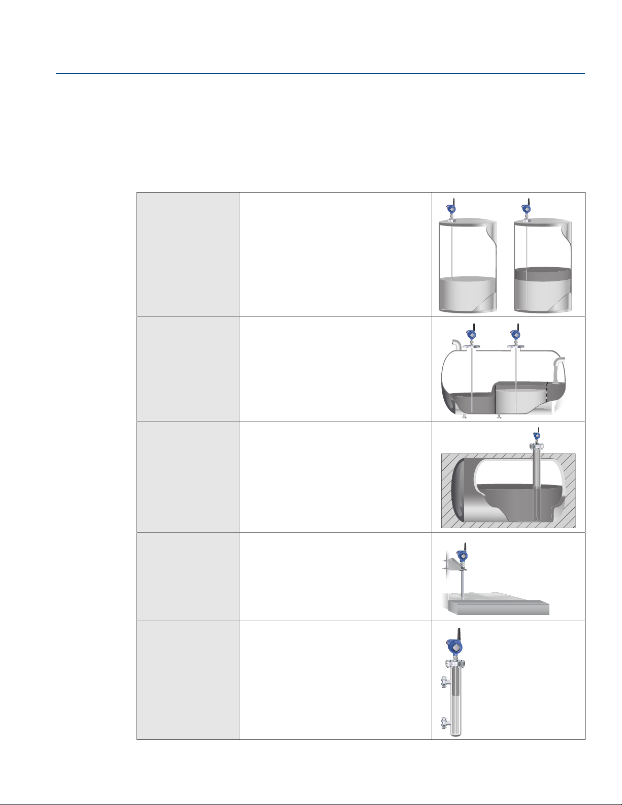
2.4 Application examples
The Rosemount 3308 Series Transmitter is suited for aggregate (total) level measurements on a wide
range of liquids, semi-liquids, and liquid to liquid interfaces.
Moreover, the reliable and accurate guided wave radar technology offers a versatile solution that is
virtually unaffected by process conditions such as temperature, pressure, vapor gas mixtures, density,
turbulence, bubbling/boiling, varying dielectric media, pH, and viscosity.
Transmitter Overview
January 2018
Storage and buffer
tanks
Low pressure
separators
Waste tanks and
sump pits
The Rosemount 3308 Series Transmitter is
ideal for storage or buffer tanks for almost
any liquid, such as oil, gas condensate,
water, or chemicals.
The Rosemount 3308 Series Transmitter
can measure both level and interface level,
such as for separator applications.
The Rosemount 3308 Series Transmitter is
a good choice for waste tanks and
underground tanks, such as sump pits.
Tra nsm itter O verview
Open applications —
ponds, basins,
sumps
Chamber
applications
The Rosemount 3308 Series Transmitter
can be installed in open air to measure
liquids not contained in a tank.
The Rosemount 3308 Series Transmitter is
a good choice for both chamber and pipe
installations.
9
Page 22
Transmitter Overview
D
FG
E
A
B
C
HI JKL
January 2018
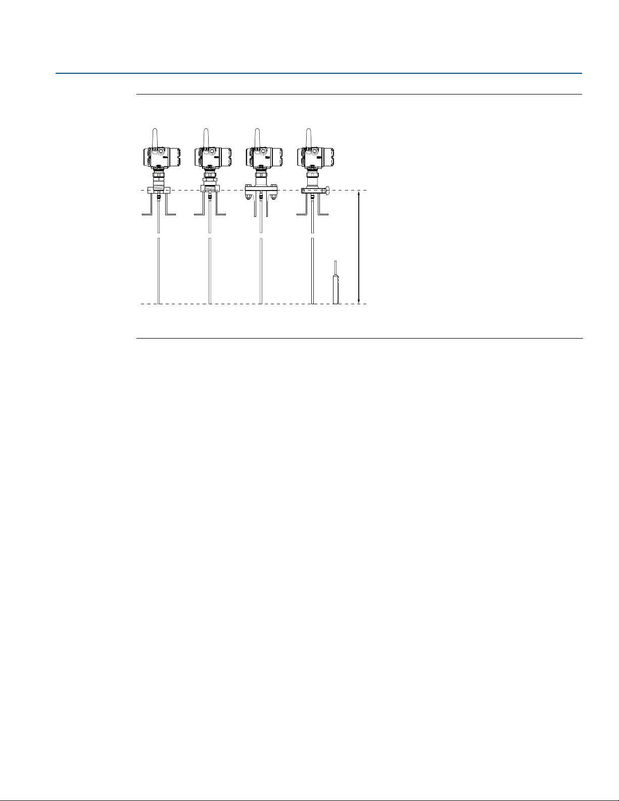
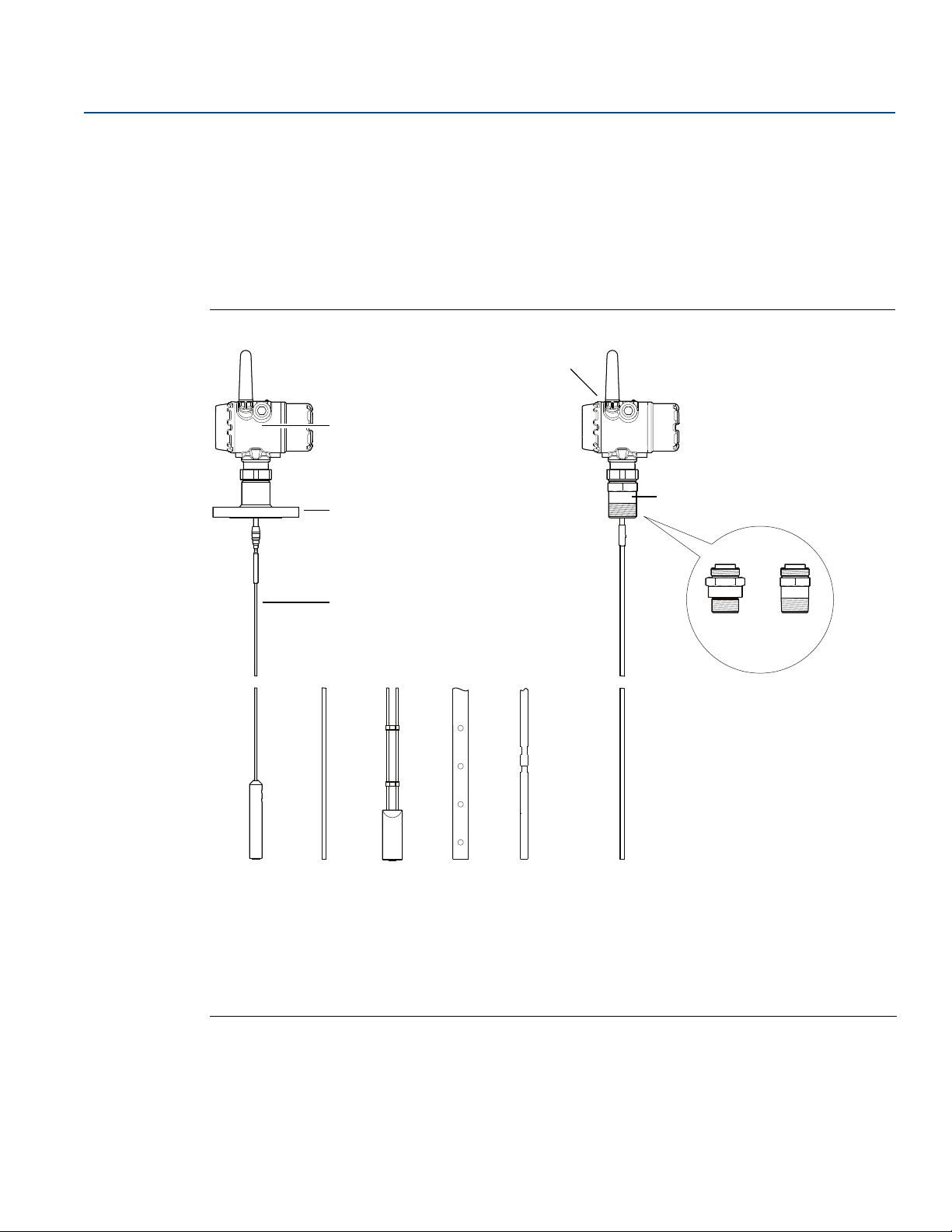
2.5 Components of the transmitter
The Rosemount 3308 Series transmitter housing contains advanced electronics for signal processing.
The transmitter housing is made of aluminum or stainless steel, depending on specified option code.
The radar electronics produces an electromagnetic pulse which is guided by the probe.
There are different probe types available for various applications: Flexible Single Lead, Rigid Single Lead,
Flexible Twin Lead, and Coaxial.
Figure 2-7. Transmitter Components
Reference Manual
00809-0100-4308, Rev CB
A. Radar Electronics G. NPT
B. Flanged Process Connections H. Flexible Single Lead with weight
C. Probe I. Rigid Single Lead
D. Dual Compartment Housing J. Flexible Twin Lead with weight
E. Threaded Process Connections K. Coaxial
F. BSPP (G) L. Segmented rigid single lead probe
10
Tra nsmitter O verview
Page 23

Reference Manual
00809-0100-4308, Rev CB
Transmitter Overview
January 2018
2.6 Probe selection guide
Use the following guidelines to choose appropriate probe for your Rosemount 3308 Series transmitter:
Table 2-1. Probe Selection Guide. G=Good, NR=Not Recommended, AD=Application Dependent (consult factory)
Flexible single
lead
Rigid single lead,
segmented rigid
Flexible twin
lead
Coaxial
single lead
Measurements
Level G G G G
Interface (liquid/liquid) G G G G
Process medium characteristics
Changing density G G G G
Changing dielectric
Wide pH variations G G G G
Pressure changes G G G G
Tem per atu re cha nge s G G G G
Condensing vapors G G G G
Bubbling/boiling surfaces G G G G
Foam (mechanical avoidance) NR NR NR AD
Foam (top of foam measurement) AD AD AD NR
Foam (foam and liquid measurement) AD AD AD NR
Clean liquids G G G G
Liquid with dielectric<2.0
Coating liquids
Viscous liquids
Crystallizing liquids AD AD NR NR
Solids/Powders NR NR NR NR
Fibrous liquids G G NR NR
Tank environment considerations
(2)
(3)
(4)
(4)
GGGG
AD AD AD AD
G G NR NR
GGADNR
(1)
Probe is close (<12 in./30 cm) to disturbing objects NR NR AD G
Tall and narrow mounting nozzles
(diameter <6 in./15 cm and height>diameter + 4 in./10 cm)
Probe might touch nozzle / disturbing object NR NR NR G
Liquid or vapor spray might touch probe NR NR NR G
High turbulence AD
Turbulent conditions causing breaking forces AD NR AD NR
Non-metallic tanks or open atmosphere applications AD
1. Not in fully submerged applications.
2. For overall level applications a changing dielectric has no effect on the measurement. For interface measurements a changing dielectric of the top fluid will degrade the
accuracy of the interface measurement.
3. See Table A-1 on page 113 for more information.
4. See Table A-2 on page 113 for more information.
5. Ok If probe is anchored.
6. Not suitable in applications with disturbing EMC from nearby equipment.
Tra nsm itter O verview
AD AD AD G
(5)
(6)
GAD
(6)
AD
AD
(5)
(6)
G
G
11
Page 24

Transmitter Overview
January 2018
Reference Manual
00809-0100-4308, Rev CB
12
Tra nsmitter O verview
Page 25

Reference Manual
00809-0100-4308, Rev CB
Section 3 Installation
Safety messages . . . . . . . . . . . . . . . . . . . . . . . . . . . . . . . . . . . . . . . . . . . . . . . . . . . . . . . . . . . . . . . . . . . . . page 13
Installation procedure . . . . . . . . . . . . . . . . . . . . . . . . . . . . . . . . . . . . . . . . . . . . . . . . . . . . . . . . . . . . . . . . page 15
Review mounting considerations . . . . . . . . . . . . . . . . . . . . . . . . . . . . . . . . . . . . . . . . . . . . . . . . . . . . . . page 16
Review mounting preparations . . . . . . . . . . . . . . . . . . . . . . . . . . . . . . . . . . . . . . . . . . . . . . . . . . . . . . . . page 22
Anchor the probe . . . . . . . . . . . . . . . . . . . . . . . . . . . . . . . . . . . . . . . . . . . . . . . . . . . . . . . . . . . . . . . . . . . . page 33
Mount device on tank . . . . . . . . . . . . . . . . . . . . . . . . . . . . . . . . . . . . . . . . . . . . . . . . . . . . . . . . . . . . . . . . page 36
Ground the device . . . . . . . . . . . . . . . . . . . . . . . . . . . . . . . . . . . . . . . . . . . . . . . . . . . . . . . . . . . . . . . . . . . page 54
Install the power module . . . . . . . . . . . . . . . . . . . . . . . . . . . . . . . . . . . . . . . . . . . . . . . . . . . . . . . . . . . . . page 55
Position the antenna . . . . . . . . . . . . . . . . . . . . . . . . . . . . . . . . . . . . . . . . . . . . . . . . . . . . . . . . . . . . . . . . . page 55
Utilize the device display . . . . . . . . . . . . . . . . . . . . . . . . . . . . . . . . . . . . . . . . . . . . . . . . . . . . . . . . . . . . . . page 56
3.1 Safety messages
Installation
January 2018
Procedures and instructions in this section may require special precautions to ensure the safety of the
personnel performing the operations. Information that raises potential safety issues is indicated by a
warning symbol ( ). Refer to the following safety messages before performing an operation preceded
by this symbol.
Failure to follow safe installation guidelines could result in death or serious injury.
Verify that the operating environment of the gauge is consistent with the appropriate hazardous
locations certifications.
Make sure the transmitter is installed by qualified personnel and in accordance with applicable code
of practice.
Use the equipment only as specified in this manual. Failure to do so may impair the protection
provided by the equipment.
Explosions could result in death or serious injury.
Verify that the operating environment of the gauge is consistent with the appropriate hazardous
locations certifications.
Installation of device in an explosive environment must be in accordance with appropriate local,
national and international standards, codes, and practices.
Ensure device is installed in accordance with intrinsically safe or non-incendive field practices.
Installation
13
Page 26
Installation
January 2018
Reference Manual
00809-0100-4308, Rev CB
Electrical shock can result in death or serious injury.
Ground device on non-metallic tanks (e.g. fiberglass tanks) to prevent electrostatic charge build-up.
Single lead probes are sensitive for strong electromagnetic fields and therefore not suitable for
non-metallic tanks.
Care must be taken during transportation of power module to prevent electrostatic charge build-up.
Device must be installed to ensure a minimum antenna separation distance of 8 in. (20 cm) from all
persons.
Probes covered with plastic and/or with plastic discs may generate an ignition-capable level of
electrostatic charge under certain extreme conditions. Therefore, when the probe is used in a
potentially explosive atmosphere, appropriate measures must be taken to prevent electrostatic
discharge.
Process leaks could result in death or serious injury.
Only qualified personnel should install the equipment.
Install transmitter prior to process start-up.
Install and tighten process connectors before applying pressure.
Handle the transmitter carefully.
Do not remove the transmitter while in operation.
If the process seal is damaged, gas could escape from the tank when removing the transmitter head
from the probe.
14
Electronic boards are electrostatically sensitive. Failure to observe proper handling precautions for
static-sensitive components can result in damage to the electronic components. Do not remove the
electronic boards from the Rosemount
™
3308 Series Transmitter.
To ensure long life for your radar transmitter, and to comply with hazardous location installation
requirements, tighten covers on both sides of the electronics housing.
Any substitution of non-recognized parts may jeopardize safety. Repair, e.g. substitution of components
etc., may also jeopardize safety and is under no circumstances allowed.
Use caution when handling the Power Module. The Power Module may be damaged if dropped from
heights in excess of 20 ft. (6 m).
This device complies with Part 15 of the FCC Rules. Operation is subject to the following conditions: This
device may not cause harmful interference. This device must accept any interference received, including
interference that may cause undesired operation. This device must be installed to ensure a minimum
antenna separation distance of 20 cm (8 in.) from all persons.
Installation
Page 27
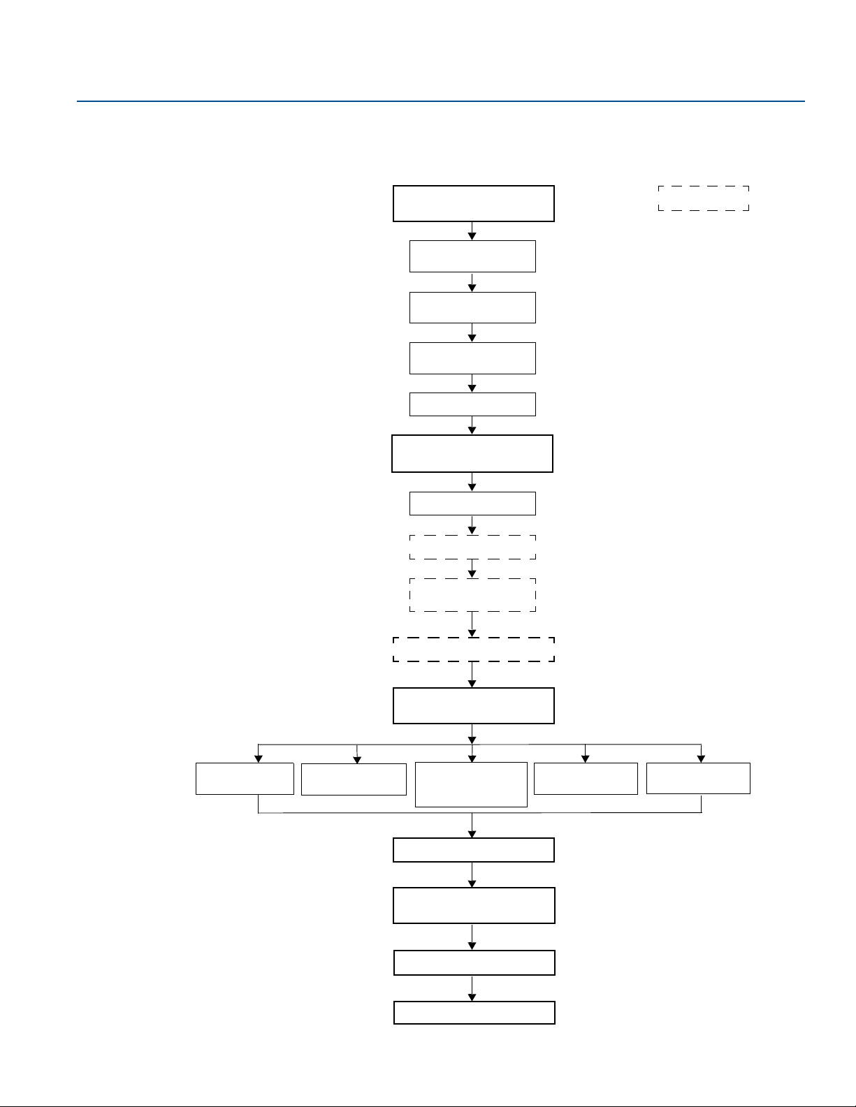
Reference Manual
Ground the device
Install the power
module
Position the antenna
Utilize the display
Threaded tank
connection
Review mounting
considerations
Review mounting
preparations
Mount device on rank
Measure tank height
Shorten the probe
Mount a centering disc
for pipe installations
Tank connection
with flange
Tank connection
with loose flange
(“plate design”)
Anchor the probe
Recommended
mounting position
Flange connection on
nozzles
Tank connection
with Tri Clamp
Optional
Segmented probe
Non-metallic tanks
Installation in still
pipe/chamber
00809-0100-4308, Rev CB
3.2 Installation procedure
Follow these steps for proper installation:
Installation
January 2018
Installation
15
Page 28
Installation
A
C
B
January 2018
3.3 Review mounting considerations
Before installing the Rosemount 3308 Series Transmitter, consider recommendations for sufficient free
space, mounting position and special needs for non-metallic tanks.
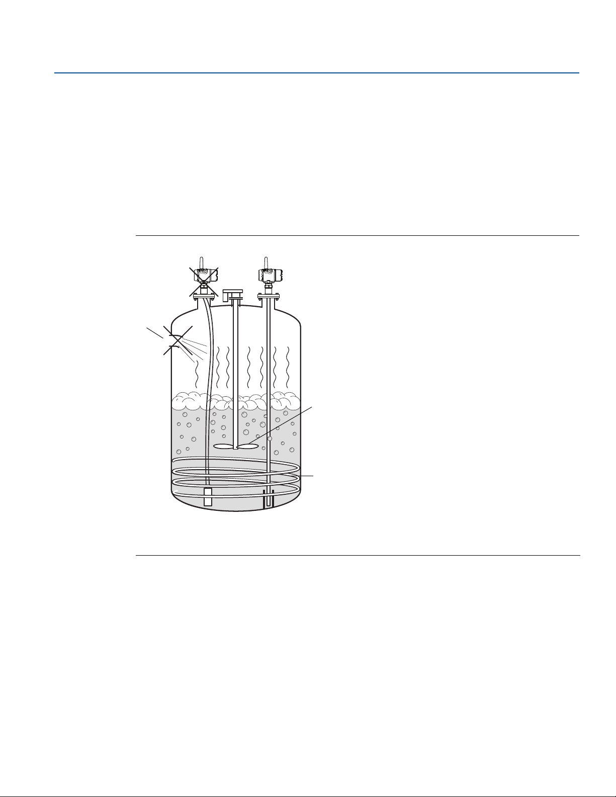
3.3.1 Recommended mounting position
When finding an appropriate mounting position for the transmitter, the conditions of the tank must be
carefully considered. The transmitter should be mounted so that the influence of disturbing objects is
reduced to a minimum. For easy access to the transmitter make sure that it is mounted with sufficient
service space.
Figure 3-1. Mounting Position
Reference Manual
00809-0100-4308, Rev CB
A. Inlet pipe
B. Agitator
C. Heating coils
The following guidelines should be considered when mounting the transmitter:
Do not mount close to inlet pipes.
Do not mount close to agitators. If the probe can move to within 12 in. (30 cm) away from an agitator,
the probe should be anchored. See “Anchor the probe” on page 33 for more information.
If the probe tends to sway due to turbulent conditions in the tank, the probe should be anchored. See
“Anchor the probe” on page 33 for more information.
Avoid mounting close to heating coils.
Position the probe such that it is subject to a minimum of lateral force.
Make sure the probe does not come into contact with the nozzle or other objects in the tank.
16
Installation
Page 29
Reference Manual
A
00809-0100-4308, Rev CB
Make sure the nozzle does not extend into the tank.
Note
Violent fluid movements causing high sideway forces may break rigid probes.
If the probe is mounted close to a wall, nozzle or other tank obstruction, noise might appear in the level
signal. Therefore the following minimum clearance, according to Tab l e 3 - 1, must be maintained.
Figure 3-2. Free Space Requirement
Installation
January 2018
Installation
A. Clearance to tank wall
Table 3-1. Recommended Minimum Free Space to Tank Wall or Other Objects in the Tank
Probe type Condition Minimum clearance (A)
Rigid single/Flexible single/
Segmented rigid single lead
Flexible twin
Coaxial N/A 0 in. (0 mm)
Smooth metal wall 4 in. (100 mm)
Disturbing objects such as pipes and
beams, or rugged metal tank walls
Smooth metal wall 4 in. (100 mm)
Disturbing objects such as pipes and
beams, or rugged metal tank walls
16 in. (400 mm)
16 in. (400 mm)
17
Page 30
Installation
A
B
January 2018
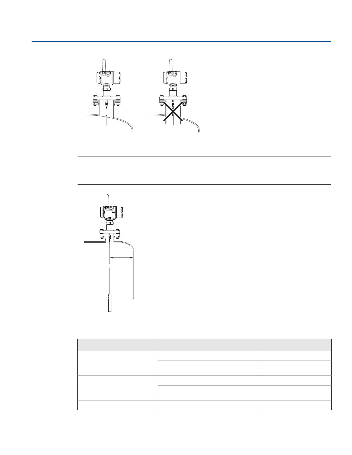
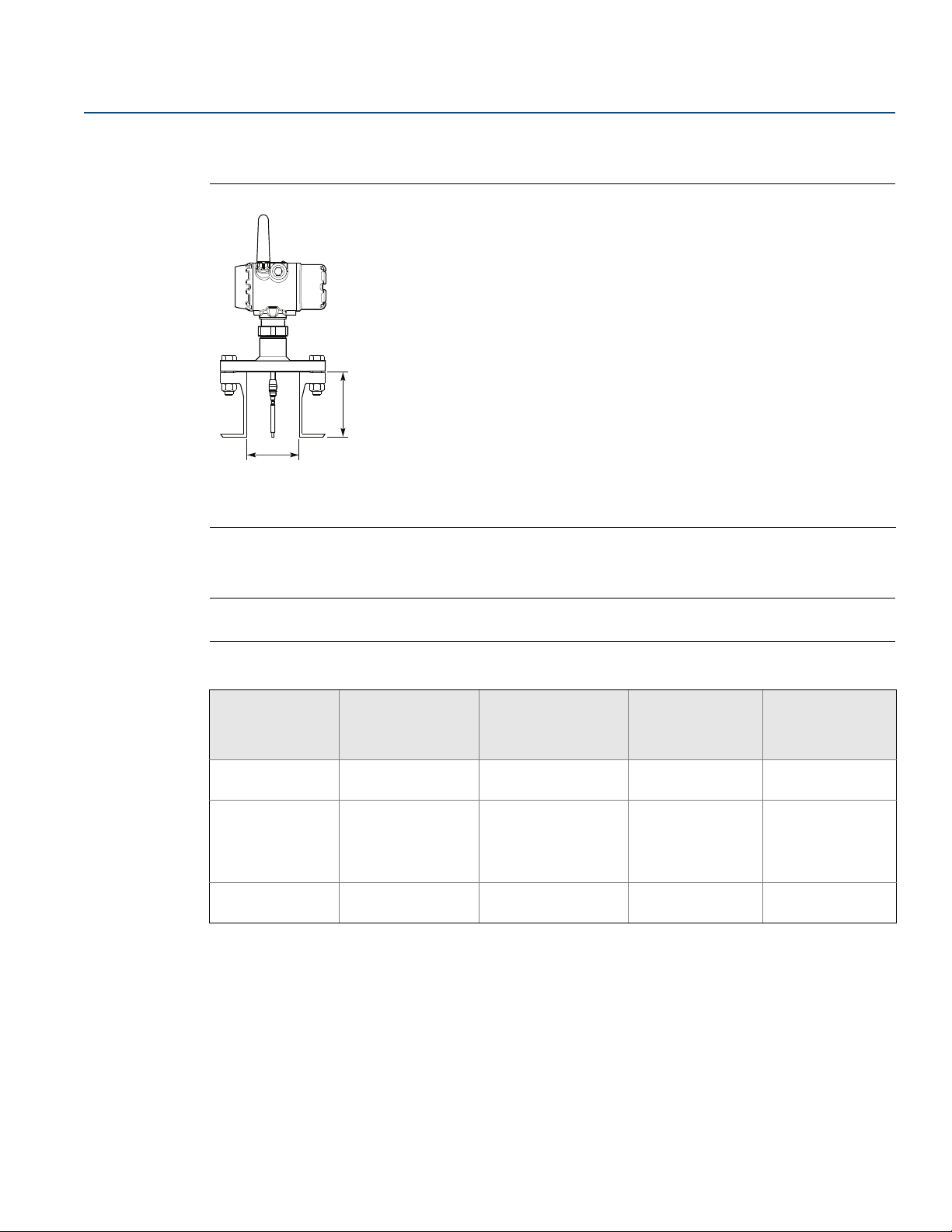
3.3.2 Flange connection on nozzles
Figure 3-3. Mounting in Nozzles
A. Maximum nozzle height
B. Minimum nozzle diameter
Reference Manual
00809-0100-4308, Rev CB
The transmitter can be mounted in nozzles by using an appropriate flange. It is recommended that the
nozzle size is within the dimensions given in Tab l e 3 -2 .
Note
The probe must not be in contact with the nozzle (except for the coaxial probe).
Table 3-2. Nozzle Considerations
Description Flexible single
lead probe
Rigid single lead
probe/Segmented
Flexible twin
lead probe
Coaxial probe
rigid single lead
Recommended
nozzle diameter
Minimum nozzle
diameter
Maximum nozzle
height
1. The Trim Near Zone (TNZ) function may be necessary or an Upper Null Zone (UNZ) setup may be required to mask the nozzle.
2. Recommended maximum nozzle height. For coaxial probes there is no limitation on nozzle height.
3. For nozzles taller than 4 in. (100 mm), the Long Stud version is recommended (option code LS) to prevent the flexible portion from touching
(1)
(2)
the edge of the nozzle.
4 in. (100 mm) or
more
1.5 in. (38 mm)
4 in. (100 mm)
+ nozzle diameter
4 in. (100 mm) or
more
1.5 in. (38 mm) for
probe type 4A
2 in. (50 mm) for
probe type 4B and 4S
4 in. (100 mm)
(3)
+ nozzle diameter
4 in. (100 mm) or
more
2 in. (50 mm) > probe diameter
4 in. (100 mm)
+ nozzle diameter
> probe diameter
N/A
18
Installation
Page 31

Reference Manual
Metal flange Metal sheet
(d > 14 in./350 mm)
00809-0100-4308, Rev CB
Installation
January 2018
3.3.3 Installation in non-metallic tanks and open-air applications
Avoid major sources of electrical disturbance in proximity of the installation, e.g. electrical motors,
stirrers, servo mechanisms.
Figure 3-4. Avoid Electromagnetic Disturbances
For clean liquids, use a coaxial probe to reduce effect of potential electrical disturbances.
Figure 3-5. Coaxial Probe in an Open-Air Application
For optimal single lead probe performance in non-metallic tanks, the probe must be mounted with a
metal flange, or screwed in to a metal sheet (d > 14 in./350 mm) if a threaded version is used.
Figure 3-6. Mounting in Non-Metallic Tanks
Installation
19
Page 32

Installation
Centre-to-centre
Side-and-bottom
dimension
Side-and-side
dimension
Centre-to-centre
January 2018
3.3.4 Installation in still pipe/chamber
General chamber considerations
A chamber or pipe installation is the preferred option due to the increase in stability and performance of
the transmitter. When selecting a smaller diameter chamber or pipe (such as 2-in.) a flexible probe is not
suitable due to the chance of it coming into contact with the walls, and relatively large side inlets may
interfere with the signal.
When gas lift and/or turbulence may occur (e.g. boiling hydrocarbons), a 3- or 4-in. chamber/pipe
diameter is recommended for maximum measurement reliability. This is especially true in high pressure
and high temperature installations.
Rosemount 9901 Chamber
Rosemount 9901 allows external mounting of process level instrumentation. It supports a variety of
process connections, and optional drain and vent connections. The Rosemount 9901 chamber is
designed to the ASME B31.3 standard, and is Pressure Equipment Directive (PED) compliant. Use option
code XC to order together with the Rosemount 3308 Series Transmitters.
Figure 3-7. Side-and-Side and Side-and-Bottom Chambers
Reference Manual
00809-0100-4308, Rev CB
20
The probe length to use for a Rosemount 9901 chamber can be calculated with this formula:
Side-and-side dimension:
Probe length=Centre-to-centre dimension + 19 in. (48 cm)
Side-and-bottom dimension:
Probe length=Centre-to-centre dimension + 4 in. (10 cm)
Use a centering disc the same diameter as the chamber if the probe length >3.3 ft. (1 m). See Table 3- 5
on page 28 for which disc to use.
For additional information, see the Rosemount 9901 Chamber for Process Level Instrumentation Product
Data Sheet.
Installation
Page 33

Reference Manual
A
C
B
00809-0100-4308, Rev CB
Existing chamber
A Rosemount 3308 Series Transmitter is the perfect replacement in an existing displacer chamber.
Proprietary flanges are offered, enabling use of existing chambers to make installation easy.
Figure 3-8. Existing Displacer Chamber
A. Replace chamber flange
B. Probe length
C. Displacer Length
Installation
January 2018
Considerations when changing to Rosemount 3308 Series:
The 3308 Series flange choice and probe length must be correctly matched to the chamber. Both
standard ANSI and EN (DIN), as well as proprietary chamber flanges, are available. See Table A-19 on
page 146 to identify the proprietary flanges.
See Table 3-5 on page 28 for guidelines on which disc size to use.
See Tab l e 3 - 3 for guidelines on the required probe length.
Table 3-3. Required Probe Length in Chambers
Chamber manufacturer Probe length
Major torque-tube manufacture (249B, 249C, 249K, 249N, 259B) Displacer + 9 in. (229 mm)
Masoneilan™ (Torque tube operated), proprietary flange Displacer + 8 in. (203 mm)
Other - torque tube
Magnetrol® (spring operated)
Others - spring operated
1. If flushing ring is used, add the ring height to the probe length.
2. For other manufacturers, there are small variations. This is an approximate value, actual length should be verified.
3. Lengths vary depending on model, SG and rating, and should be verified.
(2)
(3)
(2)
Displacer + 8 in. (203 mm)
Displacer + between 7.8 in. (195 mm) to 15
in. (383 mm)
Displacer + 19.7 in. (500 mm)
For additional information, see the Replacing Displacers with Guided Wave Radar Technical Note
(1)
.
Probe type in chamber considerations
Installation
When installing a Rosemount 3308 in a chamber, the single lead probe is recommended. The probe
length determines if a single rigid or single flexible probe should be used:
Less than 19.7 ft. (6.0 m): Rigid single probe is recommended. Use a centering disc for probe > 3.3 ft.
(1 m). When mounting space is limited, use a flexible single probe with a weight and centering disc.
More than 19.7 ft. (6.0 m): Use flexible single probe with a weight and centering disc.
PTFE covered probes are not recommended for chamber/pipe installations.
21
Page 34

Installation
A
C
B
January 2018
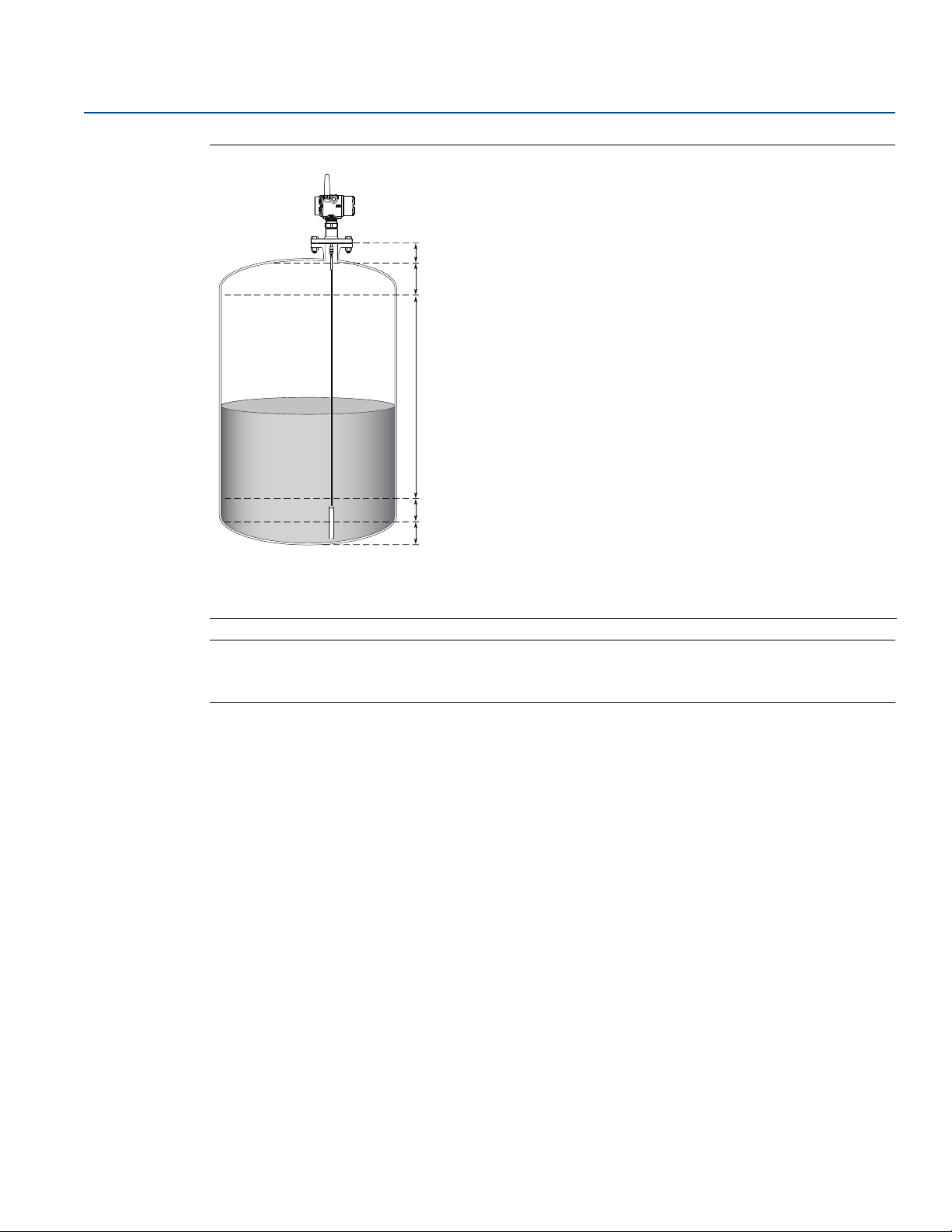
3.4 Review mounting preparations
3.4.1 Measure tank height
The Tank Height is defined as the measured distance from the Upper Reference Point to the Zero
Reference Point.
Figure 3-9. Measure Tank Height
Reference Manual
00809-0100-4308, Rev CB
A. Upper Reference Point
B. Tank He ight
C. Zero Reference Point
22
Installation
Page 35

Reference Manual
A
B
00809-0100-4308, Rev CB
3.4.2 Shorten the probe
In order to leave some clearance distance between the probe end and the tank bottom, the probe might
have to be shortened. The goal is to have the probe hang straight so that it does not touch the wall. 2 in.
(5 cm) is a suggested value. The probe can be shortened in field. Use the following form to calculate the
probe length:
Probe Length = Tank height - 2 in. (5 cm)
After shortening the probe make sure to update the transmitter configuration to the new probe length,
see “Probe length” on page 162.
Figure 3-10. Calculate Probe Length
Installation
January 2018
Installation
A. Probe Length
B. 2 in. (5 cm) clearance
23
Page 36

Installation
January 2018
Reference Manual
00809-0100-4308, Rev CB
Flexible single/twin lead probe
Note
The PTFE covered probes must not be cut in field.
1. Mark where to cut the probe.
0
123
4
5
6
7
8
2. Remove enough spacers to make place for the weight (only flexible twin lead probes).
3. Loosen the weight.
24
Installation
Page 37

Reference Manual
00809-0100-4308, Rev CB
4. Slide the weight up.
5. Cut the probe at the mark.
Installation
January 2018
Installation
6. Fasten the weight with the following torque:
Small weight (W1): 5 Nm
Short weight (W2): 5 Nm
Heavy weight (W3): 5 Nm
Weight, flexible twin: 6 Nm
25
Page 38

Installation
January 2018
Reference Manual
00809-0100-4308, Rev CB
Rigid single lead probe
Note
The PTFE covered probes must not be cut in field.
Note
Make sure the lead is fixed while cutting.
1. Mark where to cut the probe.
0
123
4
5
6
7
8
2. Cut the probe at the mark.
26
Installation
Page 39

Reference Manual
Centering piece
Maximum shortening 23.6
in. (600 mm)
> 49 in.
(1250 mm)
Minimum probe length
15.7 in. (400 mm)
49 in.
(1250 mm)
00809-0100-4308, Rev CB
Coaxial probe
1. Mark where to cut the probe.
2. Insert the centering piece.
(The centering piece is delivered from factory and
should be used to prevent the spacers centering
the rod from coming loose).
3. Cut the tube to the desired length.
4. Move the centering piece.
5. Cut the rod inside the tube. Make sure the rod is
fixed with the centering piece while cutting.
Pipes longer than 49 in. (1250 mm) can be
Installation
January 2018
shortened by as much as 23.6 in. (600 mm).
Installation
Pipes shorter than 49 in. (1250 mm) can be cut
as long as the remaining length is not less than
15.7 in. (400 mm).
27
Page 40

Installation
D
January 2018
3.4.3 Mount a centering disc for pipe installations
To prevent the probe from contacting the chamber or pipe wall, centering discs are available for flexible
single, rigid single, and flexible twin lead probes. The disc is attached to the end of the probe. Discs are
made of stainless steel, Alloy C-276, Duplex 2205, or PTFE.
When mounting a centering disc, it is important that it fits correctly in the chamber/pipe. See Tab l e 3 - 4
for Dimension D. Ta bl e 3 - 5 shows which centering disc diameter to choose for a particular pipe.
Figure 3-11. Dimension D for Centering Discs
Table 3-4. Centering Discs Dimensions
Disc size Actual disc diameter (D)
Reference Manual
00809-0100-4308, Rev CB
2-in. 1.8 in. (45 mm)
3-in. 2.7 in. (68 mm)
4-in. 3.6 in. (92 mm)
6-in. 5.55 in. (141 mm)
8-in. 7.40 in. (188 mm)
Table 3-5. Centering Disc Size Recommendation for Different Pipe Schedules
Pipe size Pipe schedule
5s, 5 and 10s,10 40s, 40 and 80s, 80 120 160
2-in.
3-in.
4-in.
5-in.
6-in.
7-in.
8-in.
1. Schedule is not available for pipe size.
2. No centering disc is available.
2-in. 2-in. N/A
3-in. 3-in. N/A
4-in. 4-in. 4-in. 3-in.
4-in. 4-in. 4-in. 4-in.
6-in. 6-in. 4-in. 4-in.
(1)
N/A
8-in. 8-in. 6-in. 6-in.
6-in. N/A
(1)
(1)
(1)
N/A
2-in.
N/A
(2)
(1)
28
Installation
Page 41

Reference Manual
13 mm
00809-0100-4308, Rev CB
Flexible single/twin lead probe
1. Mount the centering disc at the end of the weight.
Installation
January 2018
Installation
2. Secure the bolt by folding the tab washer.
29
Page 42

Installation
A
B
A. Drilling fixture
B. Probe
Note
Do not mount the washer if the centering disc material is PTFE.
A
A. Washer
B. Centering disc
C. Bushing
B
C
January 2018
Reference Manual
00809-0100-4308, Rev CB
Rigid single lead probe (8 mm)
Note
Centering discs shall not be used with PTFE covered probes.
1. Drill one hole using the drilling fixture (included in your shipment).
2. Mount the bushing, centering disc, and washer at the probe end.
3. Insert the split pin through the bushing and the probe.
30
Installation
Page 43

Reference Manual
A
B
A. Drilling fixture
B. Probe
A
B
A
A. Bushing
B. Centering disc
00809-0100-4308, Rev CB
4. Secure the split pin.
Rigid single lead probe (13 mm)
1. Drill two holes using the drilling fixture (included in your shipment).
Installation
January 2018
Installation
2. Mount the bushings and centering disc at the probe end.
31
Page 44

Installation
0.16 in. (4 mm)
0.08 in. (2 mm)
January 2018
Reference Manual
00809-0100-4308, Rev CB
3. Adjust distance by shifting hole for split pin in lower bushing.
4. Insert the split pins through the bushings and the probe.
5. Secure the split pins.
32
Installation
Page 45

Reference Manual
A
B
00809-0100-4308, Rev CB
3.5 Anchor the probe
In turbulent tanks it may be necessary to fix the probe. Depending on the probe type, different methods
can be used to guide the probe to the tank bottom. This may be needed in order to prevent the probe
from hitting the tank wall or other objects in the tank, as well as preventing a probe from breaking.
3.5.1 Flexible single/twin lead probe
The flexible single lead probe itself can be used for anchoring. Pull the probe rope through a suitable
anchoring point, e.g. a welded eye, and fasten it with a chuck.
The length of the loop will add to the Blind Zone. The location of the chuck will determine the beginning
of the Blind Zone. See “Accuracy over measuring range” on page 114 for further information on Blind
Zones.
The Probe Length should be configured as the distance from the Upper Reference Point to the top of the
chuck.
Figure 3-12. Flexible Single Lead Probe with Chuck
Installation
January 2018
Installation
A ring (customer supplied) can be attached to the weight in a threaded (M8x14) hole at the end of the
weight. Attach the ring to a suitable anchoring point.
Figure 3-13. Flexible Twin/Single Lead Probe with Weight and Ring
A. Weight with internal threads M8x14
B. Ring
A magnet (customer supplied) can be fastened in a threaded (M8x14) hole at the end of the weight. The
probe can then be guided by placing a suitable metal plate beneath the magnet.
33
Page 46

Installation
A
A
January 2018
Figure 3-14. Flexible Twin/Single Lead Probe with Weight and Magnet
A. Magnet
3.5.2 Rigid single lead probe
The rigid single lead probe can be guided by a tube welded on the tank bottom. Tubes are customer
supplied. Make sure that the probe can move freely in order to handle thermal expansion. The
measurement accuracy will be reduced close to the tube opening.
Reference Manual
00809-0100-4308, Rev CB
Figure 3-15. Rigid Single Lead Probe with Tube
A. Drain
34
Installation
Page 47

Reference Manual
A
A
00809-0100-4308, Rev CB
3.5.3 Coaxial probe
The coaxial probe can be secured to the tank wall by fixtures fastened to the tank wall. Fixtures are
customer supplied. Make sure the probe can move freely due to thermal expansion without getting
stuck in the fixture.
Figure 3-16. Coaxial Probe Secured to the Tank Wall
A. 1.1 in. (28 mm)
Installation
January 2018
The coaxial probe can be guided by a tube welded on the tank bottom. Tubes are customer supplied.
Make sure that the probe can move freely in order to handle thermal expansion. The measurement
accuracy will be reduced close to the tube opening.
Figure 3-17. Coaxial Probe with Tube
A. Drain
Installation
35
Page 48

Installation
Gasket
January 2018
3.6 Mount device on tank
Mount the transmitter with flange on a nozzle on top of the tank. The transmitter can also be mounted
on a threaded connection. Make sure only qualified personnel perform the installation.
Note
If the transmitter head must be removed from the probe, make sure that the process seal is carefully
protected from dust and water. See “Transmitter head replacement” on page 108 for further
information.
Note
PTFE covered probes must be handled carefully to prevent damage to the coating.
3.6.1 Threaded tank connection
1. For adapters with BSPP (G) threads, place a gasket on top of the tank flange.
Reference Manual
00809-0100-4308, Rev CB
2. For adapters with NPT threads, use anti-seize paste or PTFE tape according to your site procedures.
3. Lower the transmitter and probe into the tank.
36
Installation
Page 49

Reference Manual
60 mm
52 mm / 60 mm
60 mm
Torque 30 Lbft (40 Nm)
00809-0100-4308, Rev CB
4. Loosen the nut that connects the transmitter head to the probe slightly.
5. Screw the adapter into the process connection.
Installation
January 2018
6. Rotate the transmitter head so the device display faces the desired direction.
7. Tighten the nut.
Installation
8. Continue with the grounding step.
37
Page 50

Installation
Gasket
PTFE covered probe with protective plate
January 2018
3.6.2 Tank connection with flange
1. Place a gasket on top of the tank flange.
Note
Gasket should not be used for PTFE covered probe with protective plate.
Reference Manual
00809-0100-4308, Rev CB
2. Lower the transmitter and probe with flange into the tank.
3. Tighten bolts and nuts with sufficient torque for the flange and gasket choice.
38
Installation
Page 51

Reference Manual
60 mm
60 mm
Torque 30 Lbft (40 Nm)
00809-0100-4308, Rev CB
4. Loosen the nut that connects the transmitter head to the probe slightly.
5. Rotate the transmitter head so the device display faces the desired direction.
Installation
January 2018
Installation
6. Tighten the nut.
7. Continue with the grounding step.
39
Page 52

Installation
60 mm
Gasket
January 2018
00809-0100-4308, Rev CB
3.6.3 Tank connection with loose flange (“plate design”)
The transmitter is delivered with head, flange and probe assembled into one unit. If, for some reason,
these parts have been disassembled, mount the transmitter as described below:
1. Mount the flange on the probe and tighten the flange nut.
Reference Manual
2. Place a gasket on top of the tank flange.
3. Lower the probe with flange into the tank.
4. Tighten bolts and nuts with sufficient torque for the flange and gasket choice.
40
Installation
Page 53

Reference Manual
60 mm
Torque 30 Lbft (40 Nm)
Gasket
00809-0100-4308, Rev CB
5. Mount the transmitter head.
6. Continue with the grounding step.
3.6.4 Tank connection with Tri Clamp
1. Place a gasket on top of the tank flange.
Installation
January 2018
2. Lower the transmitter and probe into the tank.
3. Fasten the Tri Clamp to the tank with a clamp.
Installation
41
Page 54

Installation
60 mm
60 mm
Torque 30 Lbft (40 Nm)
January 2018
Reference Manual
00809-0100-4308, Rev CB
4. Loosen the nut that connects the transmitter head to the probe slightly.
5. Rotate the transmitter head so the device display faces the desired direction.
6. Tighten the nut.
7. Continue with the grounding step.
42
Installation
Page 55

Reference Manual
A
B
D
G
E
C
I
J
D
E
F
H
I
D
D
31.5
(800)
15.2
(385)
00809-0100-4308, Rev CB
3.6.5 Segmented probe
Figure 3-18. Segmented Probe Parts
Installation
January 2018
Dimensions are in inches (mm).
A. Safety ring
B. Screw
C. Top segment
D. Split pin
E. PTFE washer (optional)
F. Centering disc in PTFE (optional)
G. Middle segment
H. Bottom segment (length varies depending on total probe length)
I. Bushing (for the centering disc at the probe end)
J. Bottom centering disc in PTFE or stainless steel (optional)
Installation
43
Page 56

Installation
Probe length
Probe segments box
Top Segment
~
Two turns
January 2018
Reference Manual
00809-0100-4308, Rev CB
Verify probe length
Segmented probe ordered with model code 4S
Before installation, verify the probe length (L) on the label. If the probe length needs to be adjusted, see
“Adjusting the probe length” on page 51.
SN:
L =
Segmented probe ordered as spare part kit
Before installation, the number of segments that add up to the desired probe length must be
determined. Also, the bottom segment may need to be shortened. See “Adjusting the probe length” on
page 51.
Assemble the segmented probe
Note
If there is enough space beside the tank, the probe can be assembled before inserting it into the tank.
1. Insert the stop screw to the top segment. Tighten approximately two turns.
44
Installation
Page 57

Reference Manual
Bottom Segment
Bottom Segment
00809-0100-4308, Rev CB
2. Pre-assemble the safety ring.
3. Optional: If ordered, mount the centering disc on the bottom segment of the probe.
Installation
January 2018
Installation
4. Insert the support tool.
45
Page 58

Installation
Hand tighten
January 2018
Reference Manual
00809-0100-4308, Rev CB
5. Optional: If ordered, mount the centering disc.
Note
Maximum five pcs/probe
Minimum two segments between each centering disc
6. Mount a middle segment.
46
Installation
Page 59

Reference Manual
00809-0100-4308, Rev CB
7. Secure the split pin.
Installation
January 2018
8. Insert the second support tool.
Installation
47
Page 60

Installation
Use anti-seize paste or PTFE tape
according to your site procedures.
January 2018
Reference Manual
00809-0100-4308, Rev CB
9. Remove the first support tool and lower the probe into the tank.
10. Repeat steps 5 to 9 until all segments are mounted. Make sure to finish with the top segment of the
probe.
11. Seal and protect threads.
Only for NPT threaded tank connection.
48
Installation
Page 61

Reference Manual
Flange/Tri Clamp
Threaded
Gasket
Sealant on threads (NPT)
or
Gasket (BSPP (G))
00809-0100-4308, Rev CB
12. Attach the probe to the device.
Installation
January 2018
Note
For safety reasons, at least two people are needed when mounting the device.
Make sure to hold the device above the tank. High loads can break the support tool.
13. Tighten the stop screw and slide the safety ring into the groove.
Installation
49
Page 62

Installation
Flange
Threaded
Tri Clamp
60 mm
Torque 30 Lbft (40 Nm)
January 2018
Reference Manual
00809-0100-4308, Rev CB
14. Remove the support tool.
15. Mount the device on the tank.
50
16. Rotate the housing to the desired direction.
17. Tighten the nut.
18. Continue with the grounding step.
Installation
Page 63

Reference Manual
L, desired probe length:
L
n, number of middle segments:
n
Y, length of bottom segment:
Y
Y < 0.4 in. (10 mm)
Y ≥ 0.4 in. (10 mm)
Y = 31.5 in. (800 mm)
00809-0100-4308, Rev CB
Adjusting the probe length
1. Determine L, the desired probe length.
2. Determine n, the number of middle segments needed for the desired probe length. See Tabl e 3 -6 on
page 53.
Installation
January 2018
3. Calculate Y, the length of the bottom segment. See Table 3-6 on page 53.
4. Continue as follows:
Length of bottom segment (Y) Action
Continue with step (7).
Do not use the bottom segment.
Continue with step (5) and cut the bottom segment.
1. Add one extra middle segment to the calculated n.
2. Continue with step (7).
Installation
51
Page 64

Installation
12
3
4
5
6
7
8
0
12
3
0
Y
Y
Drilling fixture
January 2018
Reference Manual
00809-0100-4308, Rev CB
5. Mark where to cut the bottom segment.
6. Cut the bottom segment at the mark.
Note
Make sure the bottom segment is fixed while cutting.
52
7. Optional: If a bottom centering disc is ordered, then drill two holes on the bottom segment using
the drilling fixture.
Installation
Page 65

Reference Manual
00809-0100-4308, Rev CB
Table 3-6. Determination of Probe Segments for Standard Seal
Installation
January 2018
Desired probe length (L)
(1)
Number of middle
Length of bottom segment (Y)
segments (n)
in. mm in. mm
15.8 ≤ L ≤ 47.2 400 ≤ L ≤ 1200 0 pc Y = L -15.8 Y = L - 400
47.2 < L ≤ 78.7 1200 < L ≤ 2000 1 pc Y = L - 47.2 Y = L - 1200
78.7 < L ≤ 110.2 2000 < L ≤ 2800 2 pcs Y = L - 78.7 Y = L - 2000
110.2 < L ≤ 141.7 2800 < L ≤ 3600 3 pcs Y = L - 110.2 Y = L - 2800
141.7 < L ≤ 173.2 3600 < L ≤ 4400 4 pcs Y = L - 141.7 Y = L - 3600
173.2 < L ≤ 204.7 4400 < L ≤ 5200 5 pcs Y = L - 173.2 Y = L - 4400
204.7 < L ≤ 236.2 5200 < L ≤ 6000 6 pcs Y = L - 204.7 Y = L - 5200
236.2 < L ≤ 267.7 6000 < L ≤ 6800 7 pcs Y = L - 236.2 Y = L - 6000
267.7 < L ≤ 299.2 6800 < L ≤ 7600 8 pcs Y = L - 267.7 Y = L - 6800
299.2 < L ≤ 330.7 7600 < L ≤ 8400 9 pcs Y = L - 299.2 Y = L - 7600
330.7 < L ≤ 362.2 8400 < L ≤ 9200 10 pcs Y = L - 330.7 Y = L - 8400
362.2 < L ≤ 393.7 9200 < L ≤ 10000 11 pcs Y = L - 362.2 Y = L - 9200
1. Maximum probe length is 32 ft. 9 in. (10 m) for the Rosemount 3308 Series.
Installation
53
Page 66

Installation
A
January 2018
3.7 Ground the device
The Rosemount 3308 Series Wireless Guided Wave Radar transmitter operates with the housing
grounded or floating. Floating systems can cause extra noise that may affect many types of readout
devices. If the signal appears noisy or erratic, grounding at a single point may solve the problem.
Grounding of the electronics enclosure should be done in accordance with local and national installation
codes. Grounding is accomplished by using the external case grounding terminal.
Non-metallic tanks
Ground device on non-metallic tanks (e.g. fiberglass tanks) to prevent electrostatic charge build-up.
There is one grounding screw connection provided, located on the housing, see Figure 3-19. The ground
screw is identified by a ground symbol:
Figure 3-19. Ground Screw
Reference Manual
00809-0100-4308, Rev CB
A. Ground screw
Note
Always use facility recommended wiring practices.
Note
Flexible twin lead probe or coaxial probe are the recommended choice for non-metallic tanks. Single
lead probes are not suited for non-metallic tanks or open atmosphere applications, due to high
susceptibility to strong electromagnetic fields.
54
Installation
Page 67

Reference Manual
Keep cover tight
00809-0100-4308, Rev CB
3.8 Install the power module
Note
Use caution when handling the power module, it may be damaged if dropped from heights in excess of
20 ft. (6 m).
1. Install the Black Power Module, SmartPower™ Solutions model number 701PBKKF into the
transmitter.
Installation
January 2018
2. Close the housing cover and tighten to site or safety specifications. Always ensure a proper seal by
tightening the electronics housing covers so that metal touches metal, but do not over tighten.
3.9 Position the antenna
The antenna should be positioned vertically, either straight up or straight down, and it should be
approximately 3 ft. (1 m) from any large structure, building, or conductive surface to allow for clear
communication to other devices.
Installation
55
Page 68

Installation
A B C D
January 2018
Figure 3-20. Antenna Positioned Vertically
3.10 Utilize the device display
If a device display is ordered, it will be shipped attached to the transmitter. The display is ordered in the
transmitter model number, option code M5.
3.10.1 Rotate the device display
Reference Manual
00809-0100-4308, Rev CB
To rotate the display in 90-degree increments:
1. Squeeze the two black tabs on opposite sides of the display. Refer to Figure 3-21.
2. Gently pull out the display.
3. Rotate the display to the desired orientation, and snap the display into place.
Figure 3-21. Device Display
A. Display Pins
B. Black tabs
C. Display
D. Cover
Note
If the device display four-pin connector is inadvertently removed from the interface board, carefully
re-insert the connector before snapping the device display back into place.
3.10.2 Retrofitting
If an existing transmitter with no display (flat electronics cover) is to be retrofitted with a new display,
order spare part kit number 00753-9004-0001(aluminum display kit) or 00753-9004-0004 (stainless
steel display kit). These kits contain an extended cover with a display viewing window, a display board,
and a display pin connector. Replace the flat cover with the extended display and tighten.
56
Installation
Page 69

Reference Manual
00809-0100-4308, Rev CB
Section 4 Configuration
Overview . . . . . . . . . . . . . . . . . . . . . . . . . . . . . . . . . . . . . . . . . . . . . . . . . . . . . . . . . . . . . . . . . . . . . . . . . . . page 57
Safety messages . . . . . . . . . . . . . . . . . . . . . . . . . . . . . . . . . . . . . . . . . . . . . . . . . . . . . . . . . . . . . . . . . . . . . page 58
Configuration procedure . . . . . . . . . . . . . . . . . . . . . . . . . . . . . . . . . . . . . . . . . . . . . . . . . . . . . . . . . . . . . page 59
System readiness . . . . . . . . . . . . . . . . . . . . . . . . . . . . . . . . . . . . . . . . . . . . . . . . . . . . . . . . . . . . . . . . . . . . page 60
Get started with your preferred configuration tool . . . . . . . . . . . . . . . . . . . . . . . . . . . . . . . . . . . . . . . page 61
Join device to wireless network . . . . . . . . . . . . . . . . . . . . . . . . . . . . . . . . . . . . . . . . . . . . . . . . . . . . . . . . page 64
Configure device using guided setup . . . . . . . . . . . . . . . . . . . . . . . . . . . . . . . . . . . . . . . . . . . . . . . . . . . page 72
Verify level . . . . . . . . . . . . . . . . . . . . . . . . . . . . . . . . . . . . . . . . . . . . . . . . . . . . . . . . . . . . . . . . . . . . . . . . . . page 74
4.1 Overview
This chapter provides information about configuration, configuration tools, and configuration
parameters.
For a proper configuration, follow the steps listed in the section “Configuration procedure” on
page 59.
The configuration can be performed using one of the described configuration tools: AMS Wireless
Configurator or a Field Communicator. The section “Get started with your preferred configuration
tool” on page 61 describes what preparations must be done in order to use the configuration tool.
Appendix D: Configuration Parameters provides extended information about the configuration
parameters. An overview of Device Descriptor (DD) menu is presented in the section “Menu overview
of the Device Descriptor (DD)” on page 160. All configuration parameters are described in section
“Configuration parameters” on page 161.
Configuration
January 2018
Config uration
57
Page 70

Configuration
January 2018
4.2 Safety messages
Instructions and procedures in this section may require special precautions to ensure the safety of the
personnel performing the operations. Information that potentially raises safety issues is indicated by a
warning symbol ( ). Refer to the following safety messages before performing an operation preceded
by this symbol.
Explosions could result in death or serious injury.
Verify that the operating environment of the gauge is consistent with the appropriate hazardous
locations certifications.
Installation of device in an explosive environment must be in accordance with appropriate local,
national and international standards, codes, and practices.
Ensure device is installed in accordance with intrinsically safe or non-incendive field practices.
Electrical shock can result in death or serious injury.
Ground device on non-metallic tanks (e.g. fiberglass tanks) to prevent electrostatic charge build-up.
Single lead probes are sensitive for strong electromagnetic fields and therefore not suitable for
non-metallic tanks.
Care must be taken during transportation of power module to prevent electrostatic charge build-up.
Device must be installed to ensure a minimum antenna separation distance of 8 in. (20 cm) from all
persons.
Reference Manual
00809-0100-4308, Rev CB
Process leaks could result in death or serious injury.
Only qualified personnel should install the equipment.
Handle the transmitter carefully.
If the process seal is damaged, gas could escape from the tank when removing the transmitter head
from the probe.
To ensure long life for your radar transmitter, and to comply with hazardous location installation
requirements, tighten covers on both sides of the electronics housing.
Use caution when handling the Power Module. The Power Module may be damaged if dropped from
heights in excess of 20 ft. (6 m).
This device complies with Part 15 of the FCC Rules. Operation is subject to the following conditions: This
device may not cause harmful interference. This device must accept any interference received, including
interference that may cause undesired operation. This device must be installed to ensure a minimum
antenna separation distance of 20 cm (8 in.) from all persons.
58
Configuration
Page 71

Reference Manual
Join device to
wireless network
Insert power module
Connect to device
Obtain network ID and
join key
Configure device
Configure update rate
Enter network ID and
join key
Veri fy device joins
Network
Connect to device
Basic setup
Optional setup
Verify level
Get started
00809-0100-4308, Rev CB
4.3 Configuration procedure
Follow these steps for proper configuration:
Configuration
January 2018
Config uration
59
Page 72

Configuration
January 2018
4.4 System readiness
4.4.1 Confirm correct device driver
Verify the latest Device Descriptor (DD) is loaded on your systems to ensure proper communication.
1. Within Ta b l e 4 - 1 , use the HART
DD.
®
Universal Revision and Device Revision numbers to find the correct
Reference Manual
00809-0100-4308, Rev CB
2. Download the latest DD at EmersonProcess.com/DeviceFiles
.
Table 4-1. Identification and Compatibility According to NAMUR NE 53
Release date Device identification DD identification Review
instructions
NAMUR
hardware
revision
December-15 1.0.xx 1.0.xx 2 7 1 00809-0100-4308 Extended length and added
January-18 1.1.xx 1.1.xx 3
1. NAMUR revision is located on the transmitter label. Differences in level 3 changes, signified above by xx, represent minor product changes as defined per NE53.
Compatibility and functionality are preserved and product can be used interchangeably.
2. HART soft ware revision can be read using a HART capable configuration tool (select Overview > Device Information > Revision s).
(1)
NAMUR
software
revision
(1)
HART
software
revision
HART universal
(2)
revision
7
Device
revision
2
Manual document
number
Review functionality
Change description
probe support
High accuracy output and
Rosemo unt
™
VeriCase support
60
Configuration
Page 73

Reference Manual
A
A
00809-0100-4308, Rev CB
Configuration
January 2018
4.5 Get started with your preferred configuration tool
4.5.1 AMS Wireless Configurator (version 12.0 or later is required)
The AMS Wireless Configurator is the recommended software tool for the wireless network devices, and
is supplied with the Emerson
Supplement for further information.
Configuration can be done by connecting to the wireless network devices either point-to-point using a
HART modem as shown in Figure4-1, or wirelessly through the Gateway as shown in Figure 4-2. Initial
configuration to join a device to the wireless network must be done point-to-point.
Figure 4-1. Connect Point-to-Point using HART Modem
™
Wireless Gateway. Refer to the AMS Wireless Configurator Manual
Config uration
A. Communication terminals
Figure 4-2. Connect Wirelessly through the Wireless Gateway
A. Wireless Gateway
61
Page 74

Configuration
January 2018
Reference Manual
00809-0100-4308, Rev CB
Get the latest Device Descriptor (DD)
The Device Descriptor (DD) is a configuration tool that is developed to assist the user through the
configuration.
The Rosemount 3308 Series DD is typically installed together with AMS Wireless Configurator. To
download the latest HART DD, visit the Emerson Device Install Kit site at:
E
mersonProcess.com/Devicefiles
After downloading, add the DD to AMS Wireless Configurator:
1. Close AMS Wireless Configurator.
2. Go to Start > Programs > AMS Device Manager and select Add Device Type.
3. Browse to the downloaded DD files and select Ok.
In the Add Device Type application, select the Help button for more information on how to complete this
operation.
Configure the HART modem interface
Before connecting to the device using a HART modem, the HART modem interface must be configured
in AMS Wireless Configurator:
1. Close AMS Wireless Configurator.
2. Go to Start > Programs > AMS Device Manager and select Network Configuration.
3. Select Add.
4. In the drop down list, select HART modem and then select Install.
5. Follow the on-screen instructions.
In the Network Configuration application, select the Help button for more information on how to
complete this operation.
Configure the wireless network interface
Before connecting to the device wirelessly using a Wireless Gateway, the wireless network must be
configured in AMS Wireless Configurator:
1. Close AMS Wireless Configurator.
2. Go to Start > Programs > AMS Device Manager and select Network Configuration.
3. Select Add.
4. In the drop down list select Wireless Network and then select Install.
5. Follow the on-screen instructions.
In the Network Configuration application, select the Help button for more information on how to
complete this operation.
62
Configuration
Page 75

Reference Manual
123
456
7809
A
00809-0100-4308, Rev CB
4.5.2 Field Communicator
This section describes how to prepare the Field Communicator to communicate with a Rosemount 3308
Series Transmitter. The Field Communicator can be used to configure the device with a point-to-point
connection. Connect the leads on the Field Communicator to the communication terminals of the
device as shown in Figure 4-3.
Figure 4-3. Connect Point-to-Point using a Field Communicator
A. Communication terminals
Configuration
January 2018
Get the latest Device Descriptor (DD)
If the DD is not installed in your Field Communicator, see the appropriate Field Communicator User’s
Manual available at Emerson.com/FieldCommunicator
Communicator with the latest DD.
for instructions on how to update the Field
Config uration
63
Page 76

Configuration
January 2018
4.6 Join device to wireless network
4.6.1 Power up the wireless device
Make sure that the Wireless Gateway is installed and functioning properly before any wireless field
devices are powered. See “Install the power module” on page 55 for further information on how to
install the power module.
Wireless devices should be powered up in order of proximity from the Gateway, beginning with the
closest. This will result in a simpler and faster network installation.
Enable Active Advertising on the Gateway to ensure that new devices join the network faster. For more
information, see the Gateway Reference Manual
Startup screen sequence
The following screens will be displayed in sequence when the power module is first connected to the
Rosemount 3308 Series Transmitter.
Figure 4-4. Startup Screen Sequence
.
Reference Manual
00809-0100-4308, Rev CB
1. All Segments ON 2. Device Identification 3. Device Information: Tag
Used to visually determine if there
are any bad segments on the
device display.
Identification string used to
determine the Device Type.
User entered tag, 8 characters
long. This screen will not display if
all characters are blank.
4. Software Revision 5. Device Information: Status 6. Primary Variable
Used to determine Device
Software Revision.
This screen will only appear if there
is a critical error which may prevent
the device from operating correctly.
Check additional status screens for
more information about failure
source, refer to “Diagnostic button
screen sequence” on page 78.
Measurement value of mapped
Primary Variable.
64
Configuration
Page 77

Reference Manual
> 6 V Good
5.2 V – 6.0 V Low
< 5.2 V Very low
00809-0100-4308, Rev CB
7. Secondary Variable 8. Electronics Temperature 9. Supply Voltage
Configuration
January 2018
Measurement value of mapped
Second Variable.
Temperature value of device
electronics.
10. Percent of Range 11. Active Alert Present
Level value in percent of total
measurement range.
This screen will only appear if there
is at least one Active Alert present.
For detailed information of the
failure source and recommended
actions, go to the Active Alerts
screen in AMS Wireless
Configurator or Field
Communicator. Refer to “Check
device status” on page 81.
Some Active Aler ts will be displayed
on the LCD display as part of the
diagnostic button screen sequence,
refer to “Diagnostic button screen
sequence” on page 78.
Voltage reading of the Power
Module.
Config uration
65
Page 78

Configuration
123
456
7809
A
B
C
January 2018
4.6.2 Connect to device
Connect a Field Communicator or a HART modem to the communication terminals as shown in
Figure 4-5.
Figure 4-5. Connect to Device
Reference Manual
00809-0100-4308, Rev CB
A. Communication terminals
B. Field Communicator
C. HART Modem
AMS Wireless Configurator: Field Communicator:
a. Start AMS Wireless Configurator.
b. Selec t View > Device Connection View.
c. Double click the device under the HART modem.
Turn on the Field Communicator and connect to the
device.
For more information on how to connect to device refer to “Get started with your preferred
configuration tool” on page 61.
66
Configuration
Page 79

Reference Manual
00809-0100-4308, Rev CB
4.6.3 Configure update rate
The Update Rate is the frequency at which a new measurement is transmitted over the wireless network.
The default update rate is 1 minute. This may be changed at commissioning, or at any time via AMS
Wireless Configurator or a Field Communicator. The Update Rate is user selectable from 4 seconds to 60
minutes.
1. Select Configure > Guided Setup > Wireless Setup.
2. Select Configure Update Rate, and follow the instructions.
Note
Make sure to set the Update Rate so that there is enough safety margin in the system for high/low alerts.
If the time between each update is too long, the high/low alerts may be triggered too late.
Run Check Level Response to make sure that configured Update Rate is sufficient for the application,
refer to section “Optional setup” on page 73.
4.6.4 Obtain network ID and join key
In order to communicate with the Wireless Gateway, and ultimately the host system, the transmitter
must be configured to communicate on the wireless network. This step is the wireless equivalent of
connecting wires from a transmitter to the host system.
Configuration
January 2018
The Network ID and Join Key may be obtained from the Wireless Gateway's integrated web interface on
the Setup > Network > Settings page, as shown in Figure 4-6.
Figure 4-6. Gateway Network Settings
Config uration
67
Page 80

Configuration
January 2018
4.6.5 Enter network ID and join key
The devices must be configured with the same Network ID and Join Key as the Gateway in order to join
the network. Use a Field Communicator or AMS Wireless Configurator to enter the Network ID and Join
Key so they match the Network ID and Join Key of the Gateway.
1. Select Configure > Guided Setup > Wireless Setup.
2. Select Join Device to Network, and follow the instructions.
If the device is not to be commissioned yet, remove the power module and fasten the housing cover. This
is to conserve power module life and to ensure safe transmitter transportation. The power module
should be inserted only when the device is ready to be commissioned.
4.6.6 Verify device joins network
Network connection can be verified in four ways, further described in this section:
1. At the device display
2. Using the AMS Wireless Configurator
3. In the Wireless Gateway's integrated web interface
Reference Manual
00809-0100-4308, Rev CB
4. Using the Field Communicator
If the Rosemount 3308 Series was configured with the Network ID and Join Key, and sufficient time has
passed, the transmitter should be connected to the network. It usually takes a few minutes for the device
to join the network. If the device has not joined the network, please see “Wireless network troubleshoot-
ing” on page 92.
Verify by device display
To verify that the device is connected to the network by the display, press the DIAG button. The display
will show: the Tag, Device Serial Number, Software Revision, Network ID, Network Connection Status,
and Device Status screens. Refer to “Diagnostic button screen sequence” on page 78.
When the network diagnostic status is displayed as “NETWK OK”, the device has successfully joined the
network. When joining the wireless network, the status displayed will be changed through the sequence
until the device finally has joined the network. Figure 4-7 on page 69 presents the different network
connection status screens.
68
Configuration
Page 81

Reference Manual
00809-0100-4308, Rev CB
Figure 4-7. Network Connection Status Screens
Network Unknown Network Restarted Network Idle
The device is still in the process of
being activated.
The device has just restarted.
Configuration
January 2018
The device is starting to join the
process.
Disconnected from Network Searching for Network Joining the Network
The device is in a disconnected
state and requires a “Force Join”
command to join the network.
Connected but in a
“quarantined” state
The device is connected to the
network, but is in a “quarantined”
state.
The device is searching for the
network.
Connected with Limited
Bandwidth
The device is joined and
operational, but is running with
limited bandwidth for sending
periodic data.
The device is attempting to join
the network.
Connected
The device has successfully joined
the network.
Config uration
69
Page 82

Configuration
January 2018
Reference Manual
00809-0100-4308, Rev CB
Verify with AMS Wireless Configurator
Start the AMS Wireless Configurator. When the device has joined the network, it will appear in the AMS
Wireless Configurator window as illustrated in Figure 4-8.
Figure 4-8. AMS Wireless Configurator Screen
Figure 4-9 presents the different network connection status images that are shown in the AMS Wireless
Configurator Overview screen.
Figure 4-9. Network Connection Status Images
Not Connected Searching Joining
Limited Bandwidth Connected
70
Configuration
Page 83

Reference Manual
00809-0100-4308, Rev CB
Verify by Gateway
To use the Wireless Gateway's integrated web interface, navigate to the Explorer > Status page as shown
in Figure 4-10. This page shows whether the device has joined the network and if it is communicating
properly.
Locate the device in question and verify all status indicators are good (green). It may take several
minutes for the device to join the network and be seen on the Gateway's integrated web interface.
Figure 4-10. Wireless Gateway Explorer Status Page
Configuration
January 2018
Verify with Field Communicator
Connect the Field Communicator as shown in Figure 4-5 on page 66. Do not remove the power module.
Removing the power module may cause the device to drop off the network.
Note
In order to communicate with a Field Communicator, the device must be powered by the power module.
To verify the device has joined the network:
1. Select Service Tools > Communications.
2. Select Join Status.
Config uration
71
Page 84

Configuration
A
B
C
A
January 2018
4.7 Configure device using guided setup
4.7.1 Connect to device
Connect to the device using your preferred configuration tool, as shown in Figure4-11 and Figure 4-12.
AMS Wireless Configurator: Field Communicator:
a. Start AMS Wireless Configurator.
b. Selec t View > Device Connection View.
c. Double click the device under the HART modem.
Figure 4-11. Connect to Device - Point-to-Point
Turn on the Field Communicator and connect to the
device.
123
456
7809
Reference Manual
00809-0100-4308, Rev CB
72
A. Communication terminals C. HART Modem
B. Field Communicator
Figure 4-12. Connect to Device - Wirelessly
A. Wireless Gateway
Configuration
Page 85

Reference Manual
00809-0100-4308, Rev CB
4.7.2 Basic setup
All Basic Setup parameters are described in the section “Configuration parameters” on page161.
Figure 4-13. Guided Setup Screen
Configuration
January 2018
1. Select Configure.
2. Select Guided Setup > Initial Setup.
3. Select Basic Setup, and follow the instructions.
4.7.3 Optional setup
Consider Optional Setup such as Volume, Device Display, Echo Tuning, and Check Level Response, found
in the Guided Setup. Run Check Level Response to review the maximum level change between updates
with the current configuration.
1. Select Configure.
2. Select Guided Setup > Optional Setup.
3. Select the desired Optional Setup, and follow the instructions.
Additional configuration parameters are available in the Manual Setup menu. For further information
about the parameters see “Configuration parameters” on page 161.
Config uration
73
Page 86

Configuration
C
D
A
B
January 2018
4.8 Verify level
Run the Verify Level tool to match the product level reported by the device to a reference measurement
(measured by using for example handgauging). If any difference, the Calibration Offset parameter will be
adjusted as shown in Figure 4-14.
A minor adjustment using Calibration Offset is normal. There may, for example be a deviation between
the actual tank height and the configured value.
Non-metallic (e.g. plastic) vessels and installation geometry may introduce an offset for the Upper
Reference Point. This offset may be up to ± 2 in. (50 mm). The offset can be compensated for using
Calibration Offset.
Note
Before running Verify Level, make sure the product surface is calm, the tank is not being filled or
emptied, and the actual level is well above the probe end.
To run Verify Level:
1. Select Configure.
Reference Manual
00809-0100-4308, Rev CB
2. Select Guided Setup > Initial Setup.
3. Select Verify Level to check your level measurement, and follow the instructions.
Figure 4-14. Calibration Offset
A. Positive Calibration Offset value
B. Negative Calibration Offset value
C. Reported level
D. Actual level
74
Configuration
Page 87

Reference Manual
00809-0100-4308, Rev CB
Section 5 Operation
Safety messages . . . . . . . . . . . . . . . . . . . . . . . . . . . . . . . . . . . . . . . . . . . . . . . . . . . . . . . . . . . . . . . . . . . . . page 75
Device display screen messages . . . . . . . . . . . . . . . . . . . . . . . . . . . . . . . . . . . . . . . . . . . . . . . . . . . . . . . page 77
View measurement values . . . . . . . . . . . . . . . . . . . . . . . . . . . . . . . . . . . . . . . . . . . . . . . . . . . . . . . . . . . . page 80
Check device status . . . . . . . . . . . . . . . . . . . . . . . . . . . . . . . . . . . . . . . . . . . . . . . . . . . . . . . . . . . . . . . . . . page 81
5.1 Safety messages
Instructions and procedures in this section may require special precautions to ensure the safety of the
personnel performing the operations. Information that potentially raises safety issues is indicated by a
warning symbol ( ). Refer to the following safety messages before performing an operation preceded
by this symbol.
Operation
January 2018
Explosions could result in death or serious injury.
Verify that the operating environment of the gauge is consistent with the appropriate hazardous
locations certifications.
Installation of device in an explosive environment must be in accordance with appropriate local,
national and international standards, codes, and practices.
Ensure device is installed in accordance with intrinsically safe or non-incendive field practices.
Electrical shock can result in death or serious injury.
Ground device on non-metallic tanks (e.g. fiberglass tanks) to prevent electrostatic charge build-up.
Single lead probes are sensitive for strong electromagnetic fields and therefore not suitable for
non-metallic tanks.
Care must be taken during transportation of power module to prevent electrostatic charge build-up.
Device must be installed to ensure a minimum antenna separation distance of 8 in. (20 cm) from all
persons.
Process leaks could result in death or serious injury.
Handle the transmitter carefully.
If the process seal is damaged, gas could escape from the tank when removing the transmitter head
from the probe.
Only qualified personnel should install the equipment.
Do not remove the transmitter while in operation.
Operation
75
Page 88

Operation
January 2018
Reference Manual
00809-0100-4308, Rev CB
To ensure long life for your radar transmitter, and to comply with hazardous location installation
requirements, tighten covers on both sides of the electronics housing.
This device complies with Part 15 of the FCC Rules. Operation is subject to the following conditions: This
device may not cause harmful interference. This device must accept any interference received, including
interference that may cause undesired operation. This device must be installed to ensure a minimum
antenna separation distance of 20 cm (8 in.) from all persons.
76
Operation
Page 89

Reference Manual
00809-0100-4308, Rev CB
5.2 Device display screen messages
The device display can be used to present different variables and a diagnostic screen sequence.
5.2.1 Variable screens
If the Display Mode is set to Periodic, the device display shows a periodic sequence of user-chosen
variables during operation. A new screen appears according to configured wireless update rate. The
device display will also show ALERT PRESNT if at least one alert is present. For information on how to
configure the device display, see “Device display” on page 165.
The Rosemount
Figure 5-1. LCD Display Variables
™
3308 Series Transmitter can display the following variables:
Operation
January 2018
Percent of Range Level Distance
Tot al Volu me Interface Distance Interface Level
Upper Product Thickness Electronics Temperature
Supply Voltage
Operation
Signal Quality
77
Page 90

Operation
January 2018
5.2.2 Diagnostic button screen sequence
The diagnostic button screen sequence on the device display can be used to obtain detailed diagnostic
information.
1. Unscrew the device display cover.
2. Press and hold the DIAG button until the first diagnostic button screen appears on the device display.
Release the DIAG button.
Reference Manual
00809-0100-4308, Rev CB
78
The device display will now automatically show the diagnostic screens as illustrated in Figure5-2.
Operation
Page 91

Reference Manual
00809-0100-4308, Rev CB
Figure 5-2. Diagnostic Button Screen Sequence
1. Device Information: Tag 2. Device Serial Number 3. Software Revision
Operation
January 2018
User entered tag which is 8
characters long. This screen will
not display if all characters are
blank.
Used to determine Device Serial
Number.
Used to determine Device
Software Revision.
4. Network ID 5. Network Connection Status 6. Active Alert Screens
(if present)
Used to determine the entered
Network ID in the device.
The screen displayed is dependent
on the progress of the device in
joining the wireless network. See
Figure 4-7 on page 69 for more
information.
See “Device display alerts” on
page 84 for a full list of Active
Alerts that may appear on this
position of the sequence.
Operation
7.Variable Screens 8. Active Alert Present
At the end of the sequence, the
device display shows all selected
variable screens.
This screen will only appear if there
is at least one Active Alert present.
For detailed information of the
failure source and recommended
actions, go to the Active Alerts
screen in AMS Wireless
Configurator or Field
Communicator. Refer to “Check
device status” on page 81.
79
Page 92

Operation
January 2018
5.3 View measurement values
Measurement values can be viewed using AMS Wireless Configurator and Field Communicator.
5.3.1 View current measurement values
Current measurement data of the Primary Variable (PV) and Secondary Variable (SV) are presented on
the Overview screen. To view all current measurement values:
1. Select Service Tools > Variables.
2. Select the desired group of measurement values to view.
To view gauges for the Primary Variable (PV), Secondary Variable (SV), Third Variable (TV) and
Fourth variable (QV), select Mapped Variables.
To view process values such as Level, Distance, Percent of Range, select Process.
To view device values such as Electronics Temperature, Supply Voltage, select Device.
To view Signal Quality, select Signal Quality.
5.3.2 View trends
Reference Manual
00809-0100-4308, Rev CB
1. Select Service Tools > Trends.
2. Select to log measurement values either in a graph or a table.
To log Level and Interface Level values in a graph, select Level.
To log Distance values in a graph, select Distance.
To log Total Volume in a graph, select Volu me.
To log Signal Quality in a graph, select Signal Quality.
To log the trend of 12 data points shown in a table, select Data History, and then select View
Data History. See “Configure data history” on page 166 for information on how to configure
device variable for recording and time between samples.
Note
Values are logged in the trend graphs only as long as the Tre nd s item is selected.
5.3.3 Interpret measurement status bars
A “Good” or “Bad” status next to a value is an indication of the reliability or integrity of the data being
received, not an indication of whether or not the value is within the configured upper or lower ranges. A
value that triggers an alert, such as a high or low temperature indication, will change the overall status of
the device, but the measurement might still be indicated as “Good” if the reliability of the data is good.
Figure 5-3. Measurement Status Bars
80
Operation
Page 93

Reference Manual
00809-0100-4308, Rev CB
5.4 Check device status
The overall device status is presented in AMS Wireless Configurator and Field Communicator under the
Overview screen. The Rosemount 3308 Series reports diagnostic alerts when there is a device
malfunction. For information on these alerts, see “Alert messages in AMS Wireless Configurator and Field
Communicator” on page 86. The device can also be configured to report user defined alerts based on the
measured variables, see “Alert setup” on page 172 for more information.
To check device status and see whether there are any Active Alerts reported, do one of the following:
The overall device status is presented in the Overview screen. If status is anything than Good, select the
button in the device status image to open a window with Active Alerts. The different device status
images can be found in Tab l e 5 -1 .
Active Alerts can also be obtained via Service Tools > Alerts > Active Alerts.
Table 5-1. Presentation of Device Status Images
Device status image Condition
Good: No active alert.
Operation
January 2018
Failed: At least one Failure Alert is active. Click the Troubleshoot
button to open a window with Active Alerts together with
recommended actions.
Maintenance: At least one Maintenance Alert is active (and no Failed
alerts). Click the Investigate button to open a window with Active
Alerts together with recommended actions.
Advisory: At least one Advisory Alert is active (and no Failed or
Maintenance Alerts). Click the Investigate button to open a window
with Active Alerts together with recommended actions.
Operation
81
Page 94

Operation
January 2018
Reference Manual
00809-0100-4308, Rev CB
82
Operation
Page 95

Reference Manual
00809-0100-4308, Rev CB
Service and Troubleshooting
Section 6 Service and Troubleshooting
Safety messages . . . . . . . . . . . . . . . . . . . . . . . . . . . . . . . . . . . . . . . . . . . . . . . . . . . . . . . . . . . . . . . . . . . . . page 83
Alert messages . . . . . . . . . . . . . . . . . . . . . . . . . . . . . . . . . . . . . . . . . . . . . . . . . . . . . . . . . . . . . . . . . . . . . . page 84
Troubleshooting guide . . . . . . . . . . . . . . . . . . . . . . . . . . . . . . . . . . . . . . . . . . . . . . . . . . . . . . . . . . . . . . . page 90
Service and troubleshooting tools . . . . . . . . . . . . . . . . . . . . . . . . . . . . . . . . . . . . . . . . . . . . . . . . . . . . . page 93
Application challenges . . . . . . . . . . . . . . . . . . . . . . . . . . . . . . . . . . . . . . . . . . . . . . . . . . . . . . . . . . . . . . page 100
Power module replacement . . . . . . . . . . . . . . . . . . . . . . . . . . . . . . . . . . . . . . . . . . . . . . . . . . . . . . . . . . page 106
Transmitter head replacement . . . . . . . . . . . . . . . . . . . . . . . . . . . . . . . . . . . . . . . . . . . . . . . . . . . . . . . page 108
Probe replacement . . . . . . . . . . . . . . . . . . . . . . . . . . . . . . . . . . . . . . . . . . . . . . . . . . . . . . . . . . . . . . . . . . page 109
Service support . . . . . . . . . . . . . . . . . . . . . . . . . . . . . . . . . . . . . . . . . . . . . . . . . . . . . . . . . . . . . . . . . . . . . page 110
6.1 Safety messages
January 2018
Procedures and instructions in this section may require special precautions to ensure the safety of the
personnel performing the operations. Information that raises potential safety issues is indicated by a
warning symbol ( ). Refer to the following safety messages before performing an operation preceded
by this symbol.
Failure to follow safe installation and servicing guidelines could result in death or serious
injury.
Make sure the transmitter is installed by qualified personnel and in accordance with applicable
code of practice.
Use the equipment only as specified in this manual. Failure to do so may impair the protection
provided by the equipment.
Electrical shock can result in death or serious injury.
Ground device on non-metallic tanks (e.g. fiberglass tanks) to prevent electrostatic charge
build-up.
Single lead probes are sensitive for strong electromagnetic fields and therefore not suitable for
non-metallic tanks.
Care must be taken during transportation of power module to prevent electrostatic charge
build-up.
Device must be installed to ensure a minimum antenna separation distance of 8 in. (20 cm) from
all persons.
Probes covered with plastic and/or with plastic discs may generate an ignition-capable level of
electrostatic charge under certain extreme conditions. Therefore, when the probe is used in a
potentially explosive atmosphere, appropriate measures must be taken to prevent electrostatic
discharge.
Service and Troubleshooting
83
Page 96

Service and Troubleshooting
January 2018
Explosions could result in death or serious injury.
Verify the operating environment of the gauge is consistent with the appropriate hazardous
locations certifications.
Installation of device in an explosive environment must be in accordance with appropriate local,
national and international standards, codes, and practices.
Ensure device is installed in accordance with intrinsically safe or non-incendive field practices.
Process leaks could result in death or serious injury.
Only qualified personnel should install the equipment.
Install transmitter prior to process start-up.
Install and tighten process connectors before applying pressure.
Handle the transmitter carefully.
Do not remove the transmitter while in operation.
If the process seal is damaged, gas could escape from the tank when removing the transmitter
head from the probe.
Reference Manual
00809-0100-4308, Rev CB
To ensure long life for your radar transmitter, and to comply with hazardous location installation
requirements, tighten covers on both sides of the electronics housing.
Any substitution of non-recognized parts may jeopardize safety. Repair, e.g. substitution of components
etc., may also jeopardize safety and is under no circumstances allowed.
Use caution when handling the Power Module. The Power Module may be damaged if dropped from
heights in excess of 20 ft. (6 m).
This device complies with Part 15 of the FCC Rules. Operation is subject to the following conditions: This
device may not cause harmful interference. This device must accept any interference received, including
interference that may cause undesired operation. This device must be installed to ensure a minimum
antenna separation distance of 20 cm (8 in.) from all persons.
6.2 Alert messages
6.2.1 Device display alerts
The following active alert screens will show the device diagnostics depending on the state of the device.
84
If the device display shows ALERT PRESNT but none of the following screens appear, then go to the Active
Alerts screen in AMS Wireless Configurator or Field Communicator for further information.
For detailed information of the failure source and recommended actions, go to the Active Alerts screen in
AMS Wireless Configurator or Field Communicator, see “Alert messages in AMS Wireless Configurator
and Field Communicator” on page 86.
Service and Troubleshooting
Page 97

Reference Manual
00809-0100-4308, Rev CB
Service and Troubleshooting
January 2018
Figure 6-1. Active Alerts Screens
Bandwidth Limited Configuration Warning Configuration Failure Electronics Warning
The device has not yet
received all of the requested
wireless bandwidth needed to
operate as configured. See
“Wireless network
troubleshooting” on page 92
for recommended actions.
The device has detected a
configuration error.
Non-critical operation of the
device may be affected.
The device has detected a
configuration error. Critical
operation of the device may
be affected.
There is a warning which
should be addressed but
should not affect the device
output.
Electronics Failure Radio Failure Sensor Warning Sensor Failure
An elec tronics er ror that could
impact the device
measurement reading has
occurred.
The wireless radio has
detected a failure or stopped
communicating.
A sensor attached to the
transmitter is degraded.
Readings from that sensor
may not be within accuracy
specifications.
A sensor attached to the
transmitter has failed, and
valid readings from that
sensor are no longer possible.
Supply Voltage Low Supply Voltage Failure
The voltage is below the
recommended operating
range. Replace the Power
Module, see “Power module
replacement” on page 106.
Service and Troubleshooting
The supply voltage is too low
and will affect device
operation. Replace the Power
Module, see “Power module
replacement” on page 106.
85
Page 98

Service and Troubleshooting
January 2018
Reference Manual
00809-0100-4308, Rev CB
6.2.2 Alert messages in AMS Wireless Configurator and Field
Communicator
Ta bl e 6 - 1 to Tab l e 6 - 4 shows list of alert messages that may be displayed in the AMS Wireless
Configurator and Field Communicator.
To view Active Alerts, select Service Tools > Alerts > Active Alerts.
Table 6-1. Failure Alerts (F:)
Message Description Recommended actions
Electronics Failure An electronics error that could impact the
device measurement reading has occurred.
Radio Failure The wireless radio has detected a failure or
stopped communicating.
Critical Power Failure The supply voltage is too low and will affect
Device Operation.
Probe Disconnected The device cannot detect the probe.
Electronics Temperature
Critical
Remote Housing Error The device has detected a problem associated
Configuration Error The device has detected a configuration error.
The internal temperature of the device has
reached critical levels and the integrity of the
device electronics may be compromised.
Environmental temperature should not
exceed device specifications.
with the remote housing.
Reasons may be multiple.
See Ta bl e 6 - 2 for a list of detailed
Configuration Errors that may be displayed.
1. Restart the device.
2. Restore the default settings and reconfigure device.
3. If the condition persists, replace the device.
1. Restart the device.
2. If the condition persists, replace the device.
1. Replace the Power Module, see “Power module
replacement” on page 106.
1. Check that the probe connection is properly
tightened.
2. Check that the probe connection is dry and clean.
3. Restart level measurements.
4. If the condition persists, replace the device and/or
the probe.
1. Verify that ambient temperature is within the
specified range. For more information about the
maximum ambient temperature, see “Temperature
limits” on page 117.
2. Remote mount the transmitter head away from the
process and environmental conditions.
3. Restart the device.
4. If the condition persists, replace the device.
1. Correct remote housing configuration to match
connected remote housing cable.
2. Check remote housing cable.
1. Click on the Details button for more information.
2. Correct the parameter causing the configuration
error.
86
Service and Troubleshooting
Page 99

Reference Manual
Service and Troubleshooting
00809-0100-4308, Rev CB
Table 6-2. Configuration Error Details (D:)
Message Description Recommended actions
January 2018
Lower Range Value or
Upper Range Value is out
of limits
Configured Measurement
Mode not Supported
Volume Configuration
Error
Unsupported Probe and
Nozzle Configuration
Parameter Out of Limits One or more of the configuration values, in a
Low Low Level Alert
configuration is invalid
Low Level Alert
configuration is invalid
High Level Alert
configuration is invalid
High High Level Alert
configuration is invalid
User Defined Alert
configuration is invalid
Signal Quality Alert
configuration is invalid
The lower/upper range value is outside the
lower/upper sensor limits. This is outside the
range where the sensor works properly, hence
the measurement may be unreliable.
The configured Measurement Mode does not
work since support has not been purchased.
The volume cannot be calculated correctly
with the current configuration.
Rigid Single Lead 0.5 in / 13 mm probe is
configured in combination with 1.5 inch
Nozzle. This combination is invalid and results
in unreliable measurement.
set that belongs together, has been changed
and reduced the measurement range of the
device.
Low Low Level Alerts will not be raised as
expected because of invalid configuration.
Low Level Alerts will not be raised as expected
because of invalid configuration.
High Level Alerts will not be raised as expected
because of invalid configuration.
High High Level Alerts will not be raised as
expected because of invalid configuration.
User Defined Alerts will not be raised as
expected because of invalid configuration.
Signal Quality Alerts will not be raised as
expected because of invalid configuration.
1. Check the lower and upper range values in relation
to the sensor limits.
1. Upgrade the device.
2. Change the Measurement Mode to match, refer to
“Measurement mode” on page 163.
1. Check that the level-volume values in the strapping
table are entered in increasing order, refer to
“Strapping table” on page 171.
2. Check that the number of strapping points to use is
correct.
3. Check size measures in the Volume Setup.
1. Install a nozzle with a supported inner diameter and
re-configure transmitter.
1. Check the configured values for Probe Length,
Vapor Dielectric Constant, and Upper Product
Dielectric Constant.
2. Restore default settings and reconfigure the device.
1. Check entered limit and deadband values in
comparison with entered tank and probe
parameters such as probe length, tank height etc.
1. Check entered limit and deadband values in
comparison with entered tank and probe
parameters such as probe length, tank height etc.
1. Check entered limit and deadband values in
comparison with entered tank and probe
parameters such as probe length, tank height etc.
1. Check entered limit and deadband values in
comparison with entered tank and probe
parameters such as probe length, tank height etc.
1. Check entered limit and deadband values in relation
to the selected variable.
1. Check entered limit and deadband values regarding
their range [0.1 – 10.0] and mutual relationship.
No user configuration
errors detected
Service and Troubleshooting
No user configuration errors detected.
87
Page 100

Service and Troubleshooting
January 2018
Table 6-3. Maintenance Alerts (M:)
Message Description Recommended actions
Reference Manual
00809-0100-4308, Rev CB
Supply Voltage Low The supply voltage is low and may affect
Device Operation.
Electronics Temperature
Out of Limits
The temperature of the electronics board
has exceeded the transmitter’s operating
range.
Level Measurement Lost No valid Level reading. Reasons may be
multiple:
No valid surface echo peak in the
measuring range.
Incorrect transmitter configuration.
Interface Measurement
Lost
No valid Interface reading. Reasons may be
multiple:
No valid surface echo peak in the
measuring range.
Incorrect transmitter configuration.
Low Signal Quality The Signal Quality is below the defined alert
limit.
Capacity Denied The device has failed to acquire the wireless
communication bandwidth necessary to
support the configured update rates.
PV Out of Limits The primary measurement is outside the
sensor limits and may be unreliable.
Non-PV Out of Limits One of the non-primary measurements is
outside the associated sensor limits and
may be unreliable.
88
1. Replace the Power Module, see “Power module
replacement” on page 106.
1. Verify that ambient temperature is within the
operating range.
2. Restart the device.
3. Remote mount the transmitter head away from the
process and environmental conditions.
4. If the condition persists, replace the device.
1. Analyze the Echo Curve for reason and check device
configuration, especially thresholds, Near Zone,
Maximum Level Rate and settings on the Lost
Measurement tab in the Alert Setup.
2. Check device physical installation (for instance probe
contamination).
3. Restart level measurement.
4. Restore default settings and reconfigure the device.
5. If the condition persists, replace the device.
1. Analyze the Echo Curve for reason and check device
configuration, especially thresholds, false echoes,
Near Zone, Maximum Level Rate and settings on the
Lost Measurement tab in the Alert Setup.
2. Check device physical installation (for instance probe
contamination).
3. Restart measurement.
4. Restore the default settings and reconfigure device.
5. If the condition persists, replace the device.
1. Take action based on your intended use of this alert.
2. Clean the probe.
3. If no actions were necessary, consider to change the limit.
1. Obtaining the bandwidth may take some time
depending on the configured update rates and other
devices in the network. Wait several minutes to see if
the error resolves itself.
2. There may be too many devices attached to the
®
WirelessHART
network, or the update rates may be
too fast. Try using a different network, or slowing
down the update rate on one or more devices.
1. Bring the system to a safe state.
2. Verify that the primary measurement is within
specified limits.
3. Restart the device.
4. If the condition persists, replace the device.
1. Bring the system to a safe state.
2. Verify that all non-primary measurements are within
specified limits.
3. Restart the device.
4. If the condition persists, replace the device
Service and Troubleshooting
 Loading...