

Reference Manual
00809-0100-4021, Rev JC
December 2019
Rosemount™ 3144P Temperature Transmitter
with Rosemount X-well™ Technology

NOTICE
Read this manual before working with the product. For personal and system safety, and for optimum product performance,
ensure you thoroughly understand the contents before installing, using, or maintaining this product.
Within the United States, Emerson has two toll-free assistance numbers:
Customer Central (Technical support, quoting, and order-related questions): 1-800-999-9307 (7:00 am to 7:00 pm Central Time)
North American Response Center (Equipment service needs): 1-800-654-7768 (24 hours)
International: (952)-906-8888
CAUTION
The products described in this document are NOT designed for nuclear-qualified applications.
Using non-nuclear qualified products in applications that require nuclear-qualified hardware or products may cause inaccurate
readings.
For information on Rosemount nuclear-qualified products, contact your local Emerson Sales Representative.
WARNING
Failure to follow these installation guidelines could result in death or serious injury.
Ensure only qualified personnel perform installation or service.
Electrical shock could cause death or serious injury.
Use extreme caution when making contact with the leads and terminals.
Explosions could result in death or serious injury.
Do not remove the connection head cover in explosive atmospheres when the circuit is live.
Before powering a FOUNDATION™ Fieldbus segment in an explosive atmosphere, ensure the instruments in the loop are installed in
accordance with intrinsically safe or non-incendive field wiring practices.
Verify that the operating atmosphere of the transmitter is consistent with the appropriate hazardous locations certifications.
All connection head covers must be fully engaged to meet explosion-proof requirements.
Process leaks could result in death or serious injury.
Do not remove the thermowell while in operation.
Install and tighten thermowells or sensors before applying pressure.
Physical access
Unauthorized personnel may potentially cause significant damage to and/or misconfiguration of end users’ equipment. This could
be intentional or unintentional and needs to be protected against.
Physical security is an important part of any security program and fundamental to protecting your system. Restrict physical access
by unauthorized personnel to protect end users’ assets. This is true for all systems used within the facility.
2

Reference Manual Contents
00809-0100-4021 December 2019
Contents
Chapter 1 Introduction.................................................................................................................. 5
1.1 Using this manual.............................................................................................................................5
1.2 Rosemount 3144P revisions............................................................................................................. 6
1.3 Confirm HART revision capability....................................................................................................10
Chapter 2 Installation...................................................................................................................11
2.1 Installation considerations..............................................................................................................11
2.2 Commissioning.............................................................................................................................. 13
2.3 Mounting....................................................................................................................................... 16
2.4 Installation..................................................................................................................................... 17
2.5 Wiring............................................................................................................................................ 23
2.6 Foundation Fieldbus....................................................................................................................... 27
2.7 Power supply..................................................................................................................................28
2.8 Grounding......................................................................................................................................29
2.9 Wire and apply power.....................................................................................................................32
Chapter 3 HART Commissioning...................................................................................................33
3.1 Overview........................................................................................................................................ 33
3.2 Confirm HART revision capability....................................................................................................33
3.3 Safety messages.............................................................................................................................34
3.4 Field Communicator.......................................................................................................................34
3.5 Review configuration data..............................................................................................................44
3.6 Check output..................................................................................................................................44
3.7 Configuration................................................................................................................................. 44
3.8 Rosemount X-well Technology configuration................................................................................. 99
3.9 Device output configuration.........................................................................................................102
3.10 Device information.....................................................................................................................104
3.11 Measurement filtering................................................................................................................106
3.12 Diagnostics and service.............................................................................................................. 108
3.13 Multidrop communication..........................................................................................................109
3.14 Use with the HART Tri-Loop........................................................................................................110
3.15 Configure Thermocouple Degradation in guided setup.............................................................. 113
3.16 Configure Thermocouple Degradation in manual setup............................................................. 118
3.17 Active Thermocouple Degradation Alerts...................................................................................123
3.18 Minimum/maximum tracking diagnostic....................................................................................128
3.19 Calibration..................................................................................................................................136
3.20 Trim the transmitter...................................................................................................................137
3.21 Output trim or scaled output trim.............................................................................................. 147
Reference Manual iii

Contents Reference Manual
December 2019 00809-0100-4021
3.22 Troubleshooting.........................................................................................................................148
Chapter 4 FOUNDATION Fieldbus Configuration......................................................................... 157
4.1 Overview...................................................................................................................................... 157
4.2 Safety messages...........................................................................................................................157
4.3 Device description........................................................................................................................157
4.4 Node address............................................................................................................................... 158
4.5 Modes.......................................................................................................................................... 158
4.6 Link Active Scheduler (LAS)...........................................................................................................159
4.7 Capabilities...................................................................................................................................159
4.8 FOUNDATION Fieldbus function blocks............................................................................................ 160
4.9 Resource block............................................................................................................................. 162
4.10 Analog Input (AI)........................................................................................................................ 175
4.11 Operation...................................................................................................................................182
4.12 Troubleshooting guides..............................................................................................................188
Chapter 5 Operation and maintenance.......................................................................................193
5.1 Safety messages...........................................................................................................................193
5.2 Maintenance................................................................................................................................ 193
5.3 Return of materials.......................................................................................................................195
Chapter 6 Safety Instrumented Systems (SIS) requirements....................................................... 197
6.1 SIS certification.............................................................................................................................197
6.2 Safety certified identification........................................................................................................197
6.3 Installation................................................................................................................................... 197
6.4 Configuration...............................................................................................................................198
6.5 Operation and maintenance.........................................................................................................200
6.6 Specifications............................................................................................................................... 201
6.7 Spare parts................................................................................................................................... 202
Appendix A Reference data........................................................................................................... 203
A.1 Product Certifications...................................................................................................................203
A.2 Ordering Information, Specifications, and Drawings.................................................................... 203
iv Rosemount 3144P

Reference Manual
00809-0100-4021 December 2019
Introduction
1 Introduction
1.1 Using this manual
The sections in this manual provide information on installing, operating, and maintaining
the Rosemount™ 3144P Temperature Transmitter. The sections are organized as follows:
• Installation contains mechanical and electrical installation instructions.
• HART Commissioning contains techniques for properly commissioning the device.
• FOUNDATION Fieldbus Configuration provides instruction on commissioning and
operating the Rosemount 3144P Transmitter. This chapter also includes information
on software functions, configuration parameters, and online variables.
• Operation and maintenance contains operation and maintenance techniques.
• Safety Instrumented Systems (SIS) Requirements provides identification, installation,
configuration, operation and maintenance, and inspection information for Safety
Instrumented Systems.
1.1.1
• Reference Data supplies reference and specification data, as well as ordering
information and contains intrinsic safety approval information, European ATEX
directive information, and approval drawings.
Transmitter
Industry-leading temperature transmitter delivers unmatched field reliability and
innovative process measurement solutions:
• Rosemount X-Well™ Technology provides a Complete Point Solution™ for accurately
measuring process temperature in monitoring applications without the requirement of
a thermowell or process penetration
• Superior accuracy and stability
• Dual and single sensor capability with universal sensor inputs (RTD, T/C, mV, ohms)
• Comprehensive sensor and process diagnostics offering
• IEC 61508 safety certification
• Dual-compartment housing
• Large LCD display
• Selectable HART® Revision (5 and 7) or FOUNDATION Fieldbus protocols
Improve efficiency with Best-in-Class product specifications and capabilities:
• Reduce maintenance and improve performance with industry leading accuracy and
stability.
• Improve measurement accuracy by 75 percent with Transmitter-Sensor Matching.
• Ensure process health with system alerts and easy-to-use Device Dashboards.
Reference Manual 5

Introduction Reference Manual
December 2019 00809-0100-4021
• Easily check device status and values on local LCD display with large percent range
graph.
• Achieve high reliability and installation ease with the industry's most rugged dual
compartment design.
Optimize measurement reliability with diagnostics designed for any protocol on any host
system.
• Thermocouple Degradation Diagnostic monitors the health of a thermocouple loop,
enabling preventative maintenance.
• Minimum and Maximum Temperature Tracking tracks and records temperature
extremes of the process sensors and the ambient environment.
• Sensor Drift Alert detects sensor drift and alerts you.
• The Hot Backup™ feature provides temperature measurement redundancy.
Refer to the following literature for a full range of compatible connection heads, sensors,
and thermowells provided by Emerson:
• Rosemount Volume 1 Temperature Sensors and Accessories Product Data Sheet
• Rosemount DIN-Style Temperature Sensors and Thermowells (Metric) Product Data
Sheet
1.2 Rosemount 3144P revisions
HART protocol
The initial release of the Rosemount 3144P HART was device revision 3. Each additional
revision contains incremental improvements. summarizes these changes.
Table 1-1: HART Revisions
Software
release date
April 2017 1.2.1 1.0.0 3 7 7
April 2012 1.1.1 N/A 2 7 6
Feb 2007 N/A N/A 1 5 4
Identify device Field device driver Review
NAMUR
software
revision
NAMUR
hardware
Revision
HART
software
revision
HART
universal
(1)
revision
5 5
5 5
(2)
)
Device
revision
(3)
(4)
(4)
(4)
instructions
Manual
document
number
00809-0100-40
21
Dec 2003 N/A N/A N/A 5 3
(1) NAMUR software revision is located in the hardware tag of the device. You can read the HART
software revision with a HART capable configuration tool.
(2) Device driver file names use device and DD devision (e.g. 10_07). HART protocol is designed to
enable legacy driver revisions to continue to communicate with new HART devices. To access this
functionality, download the new device driver. Emerson recommends downloading the new
device driver to ensure new functionality.
6 Rosemount 3144P

Reference Manual Introduction
00809-0100-4021 December 2019
(3) Rosemount X-well sensor type.
(4) HART Revision 5 and 7 selectable, Thermocouple Degradation Diagnostic, Min/Max Tracking.
FOUNDATION Fieldbus
The following table summarizes the Rosemount 3144P FOUNDATION™ Fieldbus revision
history.
Table 1-2: FOUNDATION Fieldbus Revisions
Device
revision
Rev 1 1.00.011 5 N/A N/A Initial release. Mar.
Rev 1 1.00.024 5 N/A N/A Minor product
Rev 1 1.00.024 6 N/A N/A Minor product
Rev 1 1.01.004 6 N/A N/A Software update. Oct.
Rev 1 1.01.010 7 N/A N/A Component
Rev 2 2.02.003 7 N/A N/A FF Sensor and Process
Software
revision
Hardware
revision
NAMUR
software
revision
NAMUR
hardware
revision
Description Date
2004
Sep.
maintenance, software.
maintenance,
hardware.
obsolescence hardware
change and software to
support the hardware
change.
Diagnostic Release
(D01): Thermocouple
Degradation Diagnostic
and Minimum and
Maximum Temperature
Tracking.
2004
Dec.
2004
2005
Feb.
2007
Nov.
2008
Reference Manual 7

Introduction Reference Manual
December 2019 00809-0100-4021
Table 1-2: FOUNDATION Fieldbus Revisions (continued)
Device
revision
Rev 3 3.10.23 7 1.3.1 1.0.0 Device Compliance to
Software
revision
Hardware
revision
NAMUR
software
revision
NAMUR
hardware
revision
Description Date
ITK 6.0.1. Addition of
NE107 device
diagnostic information.
Ease of use
improvements
including:
• Hot Backup
functionality has
been moved to the
transducer block,
allowing easier
configuration from
the DD.
• Device is shipped
with the simulate
switch ON, allowing
device alerts
simulation without
cover removal.
• Device has unique
block names using
the last four digits
(XXXX) of the
output board serial
number, e.g.
AI_1400_XXXX
• All blocks are
instantiated before
shipping, including
model option code
dependent blocks.
The product also
has all parameters
initialized so that its
primary
measurement is
available with no
user changes
required.
• All devices ship will
AI block scheduled.
• Customer will be
able to use old DD
files when replacing
a device with a
newer rev device;
this is possible for
devices with device
June
2013
8 Rosemount 3144P

Reference Manual Introduction
00809-0100-4021 December 2019
Device
revision
Software
revision
Hardware
revision
NAMUR
software
revision
NAMUR
hardware
revision
Description Date
revision number 3
and above.
• Wherever possible,
the product ships
with parameters
initialized to
common values.
The product shall
ship with no
uninitialized
parameters that will
keep the
transmitter from
providing its
primary
measurement right
out of the box.
• The product's
default block tags
are be less than or
equal to 16
characters in
length.
• Custom function
blocks were
replaced with
enhanced function
blocks.
• Default block tags
include
underscores, “_”,
instead of white
spaces.
• The CF file has a
better description
of the device,
including
meaningful defaults
and example values.
• Device provides
means to properly
range graphs and
charts in the device
dashboards.
Reference Manual 9

Introduction Reference Manual
December 2019 00809-0100-4021
1.3 Confirm HART revision capability
Confirm the HART capability of the system devices prior to transmitter installation.
Prerequisites
If using HART based control or asset management systems, confirm the HART capability of
those systems prior to transmitter installation. Not all systems are capable of
communicating with HART Revision 7protocol. You can configure the transmitter for
either HART Revision 5 or Revision 7.
Switch HART revision mode
If the HART configuration tool is not capable of communicating with HART Revision 7, the
transmitter will load a Generic Menu with limited capability. The following procedures will
switch the HART revision mode from the Generic Menu.
Procedure
Select Manual Setup → Device Information → Identification → Message.
a) To change to HART Revision 5, enter HART5 in the Message field.
b) To change to HART Revision 7, enter HART7 in the Message field.
10 Rosemount 3144P
(1,500
°F)
T
emperat
u
r
e
Oven
(
1,
0
00 °F)
Tempera
ture
Oven
(
4
82 °
F)
T
em
p
er
ature
Oven
Housing Temperature
Rise Above
Ambient °C (°F)
60 (108)
50 (90)
40 (72)
0
30 (54)
20 (36)
10 (18)
3
4
5 6
7 8 9
Extension Length (in.)
815 °C
250 °
C
5
40 °C
22
3.6
Reference Manual Installation
00809-0100-4021 December 2019
2 Installation
2.1 Installation considerations
2.1.1 General
Electrical temperature sensors, such as resistance temperature detectors (RTDs) and
thermocouples (T/Cs), produce low-level signals proportional to temperature. The
Rosemount X-well™ 3144P Temperature Transmitter converts low-level signals to HART
or FOUNDATION™ Fieldbus and then transmits the signals to the control system via two
power/signal wires.
®
2.1.2
2.1.3
Electrical
Proper electrical installation is essential to prevent errors due to sensor lead resistance and
electrical noise. For HART communications, the current loop must have between 250 and
1100 ohms resistance. Refer to for sensor and current loop connections. Foundation
Fieldbus devices must have proper termination and power conditioning for reliable
operation. Shielded cables must be used for Foundation Fieldbus and may only be
grounded in one place.
Temperature effects
Temperature effects
The transmitter will operate within specifications for ambient temperatures between –40
and 185 °F (–40 and 85 °C). Since heat from the process is transferred from the thermowell
to the transmitter housing, if the expected process temperature is near or beyond
specification limits, consider using additional thermowell lagging, an extension nipple, or
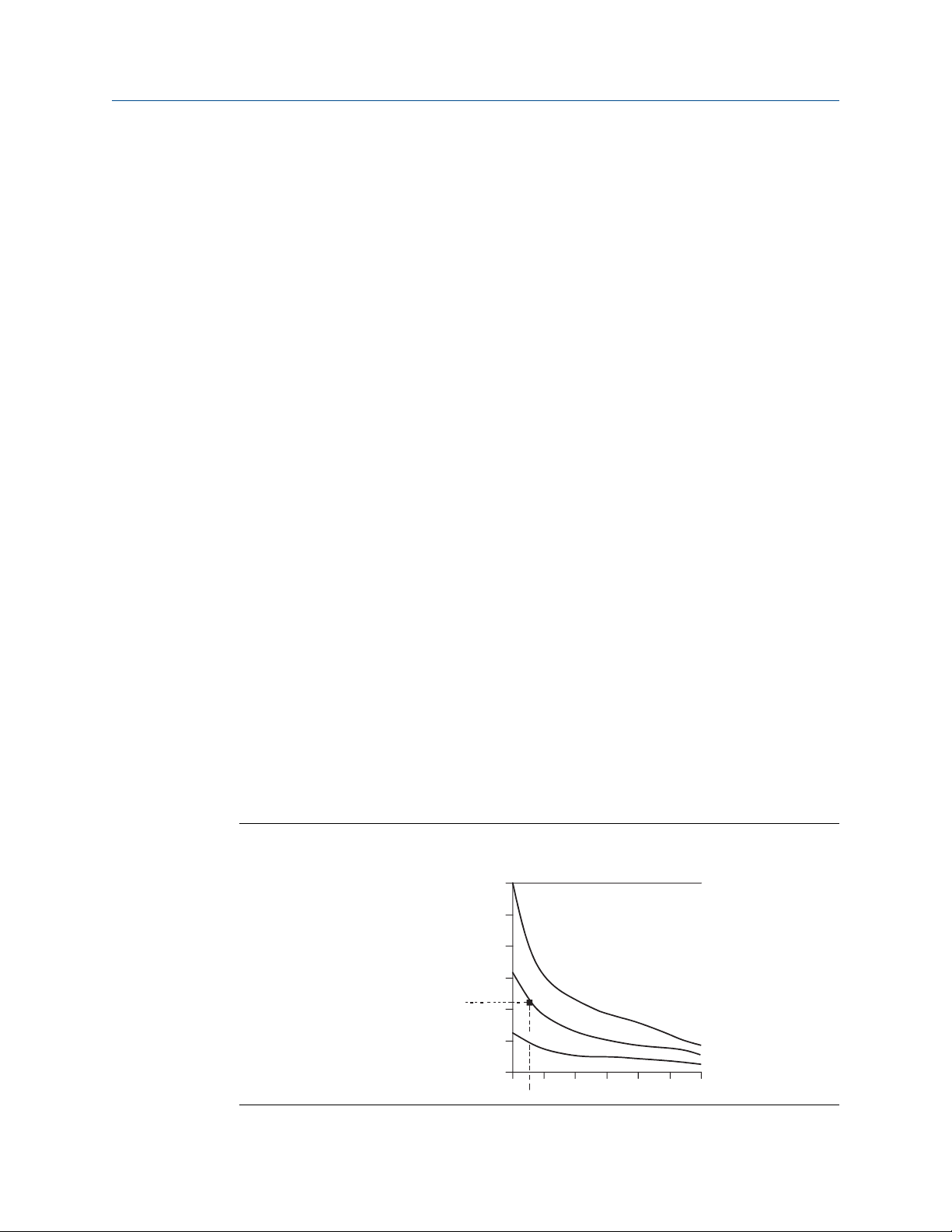
a remote mounting configuration to isolate the transmitter from the process. Figure 2-1
details the relationship between housing temperature rise and extension length.
Figure 2-1: Transmitter Housing Temperature Rise versus Extension Length for a Test
Installation
Reference Manual 11

Installation
December 2019 00809-0100-4021
Example
The maximum permissible housing temperature rise (T) can be calculated by subtracting
the maximum ambient temperature (A) from the transmitter’s ambient temperature
specification limit (S). For instance, if A = 40 °C.
T = S – A
T = 85 °C – 40 °C
T = 45 °C
For a process temperature of 540 °C (1004 °F), an extension length of 3.6-in (91.4 mm)
yields a housing temperature rise (R) of 22 °C (72 °F), providing a safety margin of 23 °C
(73 °F). A 6.0-in.(152.4 mm) extension length (R = 10 °C [50 °F]) offers a higher safety
margin (35 °C [95 °F]) and reduces temperature-effect errors but would probably require
extra transmitter support. Gauge the requirements for individual applications along this
scale. If a thermowell with lagging is used, the extension length may be reduced by the
length of the lagging.
Reference Manual
2.1.4
2.1.5
Moist or corrosive environments
The Rosemount 3144P Transmitter has a highly reliable dual compartment housing
designed to resist moisture and corrosion. The sealed electronics module is mounted in a
compartment that is isolated from the terminal side with conduit entries. O-ring seals
protect the interior when the covers are properly installed. In humid environments,
however, it is possible for moisture to accumulate in conduit lines and drain into the
housing.
Note
Each transmitter is marked with a tag indicating the approvals. Install the transmitter
according to all applicable installation codes, and approval and installation drawings (see
Rosemount 3144P Product Data Sheet). Verify that the operating atmosphere of the
transmitter is consistent with the hazardous locations certifications. Once a device labeled
with multiple approval types is installed, it should not be reinstalled using any of the other
labeled approval types. To ensure this, the approval label should be permanently marked
to distinguish the approval type(s) used.
Location and position
When choosing an installation location and position, take access to the transmitter into
account.
Terminal side of electronics housing
Mount the transmitter so the terminal side is accessible, allowing adequate clearance for
cover removal. Best practice is to mount the transmitter with the conduit entries in a
vertical position to allow for moisture drainage.
Circuit side of electronics housing
Mount the transmitter so the circuit side is accessible, providing adequate clearance for
cover removal. Additional room is required for LCD display installation. The transmitter
may be mounted directly to or remotely from the sensor. Using optional mounting
12 Rosemount 3144P
Reference Manual Installation
00809-0100-4021 December 2019
brackets, the transmitter may be mounted to a flat surface or a 2.0-in. (50.8 mm)
diameter pipe (see Mounting).
2.1.6 Software compatibility
Replacement transmitters may contain revised software that is not fully compatible with
the existing software. The latest device descriptors (DD) are available with new Field
Communicators or they can be loaded into existing communicators at any Emerson
Service Center or via the Easy Upgrade process. For more information on upgrading a Field
Communicator, see HART Commissioning.
To download new device drivers, visit Emerson.com/Rosemount/Device-Install-Kits.
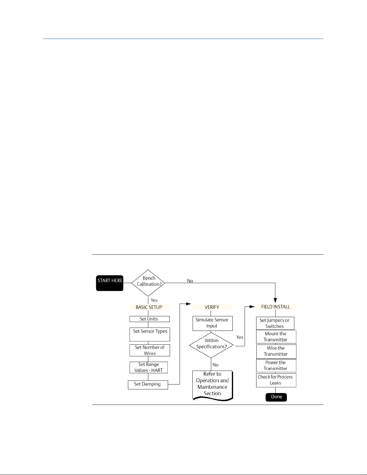
2.2 Commissioning
The transmitter must be configured for certain basic variables to operate. In many cases,
these variables are pre-configured at the factory. Configuration may be required if the
variables need to be changed.
Commissioning consists of testing the transmitter and verifying transmitter configuration
data. Transmitters can be commissioned either before or after installation. Commissioning
the transmitter on the bench before installation using a Field Communicator or AMS
Device Manager ensures that all transmitter components are in working order.
For more information on using the Field Communicator with the transmitter, see HART
Commissioning. For more information on using the Rosemount 3144 with FOUNDATION
Fieldbus, see FOUNDATION Fieldbus Configuration.
Figure 2-2: Installation Flowchart
Reference Manual 13

Installation
December 2019 00809-0100-4021
Reference Manual
2.2.1 Setting the loop to manual
Set the process application loop to manual when sending or requesting data that would
disrupt the loop or change the output of the transmitter. The Field Communicator or AMS
Device Manager will prompt to set the loop to manual, when necessary. Acknowledging
the prompt does not set the loop to manual, it is only a reminder. Setting the loop to
manual is a separate operation.
2.2.2 Set switches
The security and simulate switches are located on the top center of the electronics
module.
Note
The factory ships the simulate switch in the "ON" position.
HART
Set the switches without an LCD display
Procedure
1. If the transmitter is installed in a loop, set the loop to manual mode and disconnect
the power.
2.
Remove the housing cover on the electronics side of the transmitter. Do not
remove the transmitter cover in explosive atmospheres with a live circuit.
3. Set the switches to the desired position (see Figure 2-3).
4. Replace the transmitter cover. Both transmitter covers must be fully engaged to
meet explosion-proof requirements.
5. Apply power and set the loop to automatic mode.
Set the switches with an LCD display
Procedure
1. If the transmitter is installed in a loop, set the loop to manual mode and disconnect
the power.
2. Remove the housing cover on the electronics side of the transmitter. Do not
remove the transmitter cover in explosive atmospheres with a live circuit.
3. Unscrew the LCD display screws and gently slide the meter straight off.
4. Set the switches to the desired position (see Figure 2-3).
5. Gently slide the LCD display back into place, taking extra precautions with the 10
pin connection.
6. Replace and tighten the LCD display screws to secure the LCD display.
7. Replace the transmitter cover. Both transmitter covers must be fully engaged to
meet explosion-proof requirements.
8. Apply power and set the loop to automatic mode.
14 Rosemount 3144P
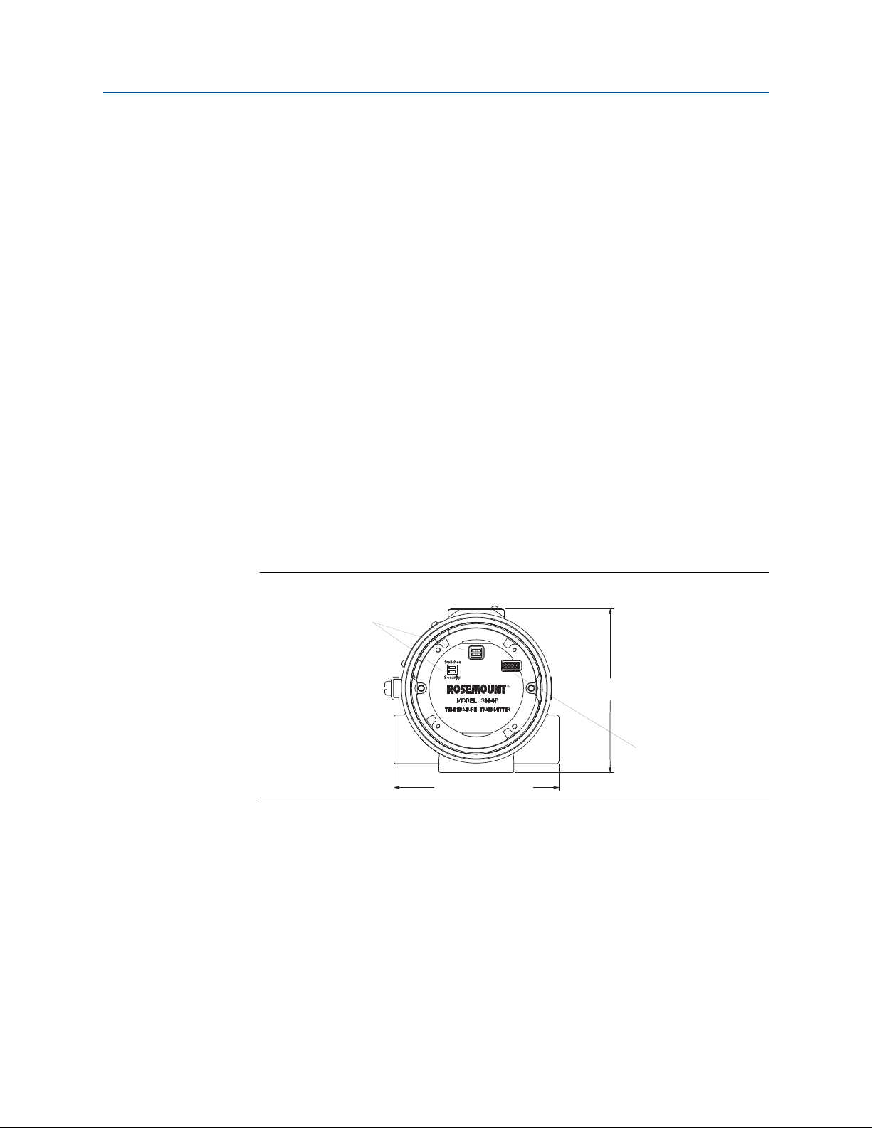
4.37-in. (110,9 mm)
4.40-in. (111,8 mm)
A
B
Reference Manual
00809-0100-4021 December 2019
Installation
FOUNDATION Fieldbus
Set switches without LCD display
Procedure
1. Set the loop to Out-of-Service (OOS) mode (if applicable) and disconnect the
power.
2. Remove the electronics housing cover.
3. Set the switches to the desired position.
4. Reattach housing cover.
5. Apply power and set the loop to in-service mode.
Set switches with LCD display
Procedure
1. Set the loop to OOS (if applicable) and disconnect the power.
2. Remove the housing cover on the electronics side of the transmitter.
3. Unscrew the LCD display screws and gently pull the meter straight off.
4. Set the switches to the desired position.
5. Replace and tighten the LCD display screws to secure the LCD display.
6. Replace the transmitter cover.
7. Apply power and set the loop to In-service mode.
Figure 2-3: Transmitter Switch Locations
Write protect switch (HART and FOUNDATION Fieldbus)
The transmitter is equipped with a write-protect switch that can be positioned to prevent
accidental or deliberate change of configuration data.
Alarm switch (HART Protocol)
An automatic diagnostic routine monitors the transmitter during normal operation. If the
diagnostic routine detects a sensor failure or an electronics failure, the transmitter goes
into alarm (high or low, depending on the position of the failure mode switch).
Reference Manual 15
Installation Reference Manual
December 2019 00809-0100-4021
The analog alarm and saturation values used by the transmitter depend on whether it is
configured to standard or NAMUR-compliant operation. These values are also customconfigurable in both the factory and the field using the HART Communications. The limits
are:
• 21.0 ≤ I ≤ 23 for high alarm
• 20.5 ≤ I ≤ 20.9 for high saturation
• 3.70 ≤ I ≤ 3.90 for low saturation
• 3.50 ≤ I ≤ 3.75 for low alarm
Note
A 0.1 mA separation between low saturation and low alarm is required.
Table 2-1: Values for Standard and NAMUR Operation
Standard operation (factory default) NAMUR-compliant operation
Fail high 21.75 mA ≤ I Fail high 21.0 mA ≤ I
High saturation 20.5 mA High saturation 20.5 mA
Low saturation 3.9 mA Low saturation 3.8 mA
Fail low I ≤ 3.75 mA Fail low I ≤ 3.6 mA
Simulate switch (FOUNDATION Fieldbus)
Simulate switch is used to replace the channel value coming from the sensor transducer
block. For testing purposes, it manually simulates the output of the analog input block to a
desired value.
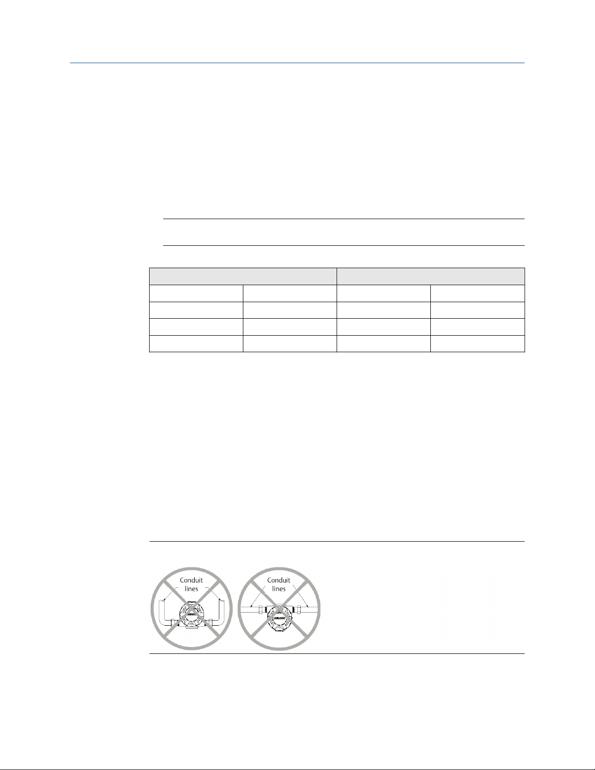
2.3 Mounting
If possible, the transmitter should be mounted at a high point in the conduit run so
moisture from the conduits will not drain into the housing. The terminal compartment
could fill with water if the transmitter is mounted at a low point in the conduit run. In some
instances, the installation of a poured conduit seal, such as the one pictured in Figure 2-5,
is advisable. Remove the terminal compartment cover periodically and inspect the
transmitter for moisture and corrosion.
Figure 2-4: Incorrect Conduit Installation
16 Rosemount 3144P
A
D
B
E
F
C
Reference Manual Installation
00809-0100-4021 December 2019
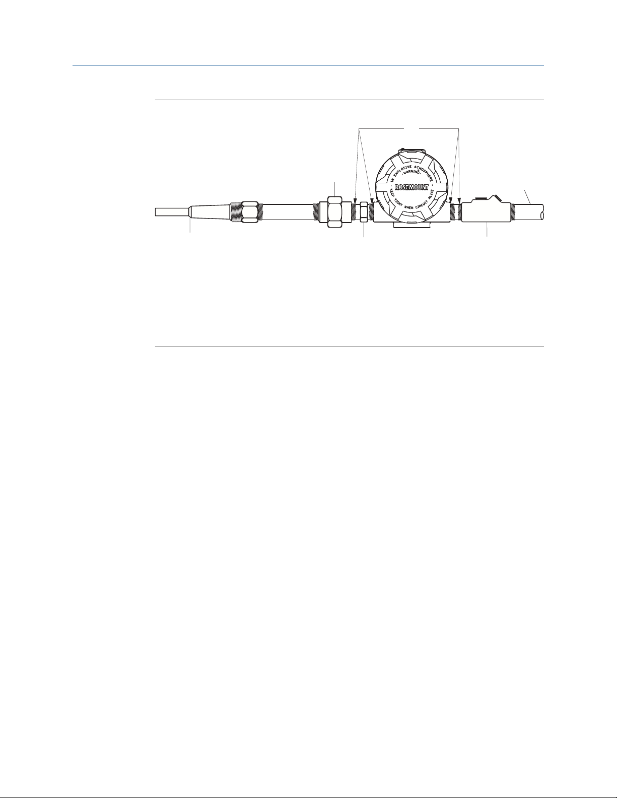
Figure 2-5: Recommended Mounting with Drain Seal
A. Sealing compound
B. Union coupling with extension
C. Conduit for field wiring
D. Thermowell
E. Sensor hex
F. Poured conduit seal (where required)
If mounting the transmitter directly to the sensor assembly, use the process shown in
Figure 2-6. If mounting the transmitter apart from the sensor assembly, use conduit
between the sensor and transmitter. The transmitter accepts male conduit fittings with ½
–14 NPT, M20 × 1.5 (CM 20), PG 13.5 (PG 11), or JIS G ½ threads (M20 × 1.5 (CM 20),
PG 13.5 (PG 11), or JIS G ½ threads are provided by an adapter). Make sure only qualified
personnel perform the installation.
The transmitter may require supplementary support under high-vibration conditions,
particularly if used with extensive thermowell lagging or long extension fittings. Pipestand mounting, using one of the optional mounting brackets, is recommended for use in
high-vibration conditions.
2.4 Installation
Installation is to be performed by qualified personnel. No special installation is required in
addition to the standard installation practices outlined in this document. Always ensure a
proper seal by installing the electronics housing cover(s) so that metal contacts metal.
The loop should be designed so the terminal voltage does not drop below 12 Vdc when
the transmitter output is 24.5 mA.
Environmental limits are available in the Rosemount 3144P Temperature Transmitter
Product Page.
Reference Manual 17
A
B
C
E
D
Installation Reference Manual
December 2019 00809-0100-4021
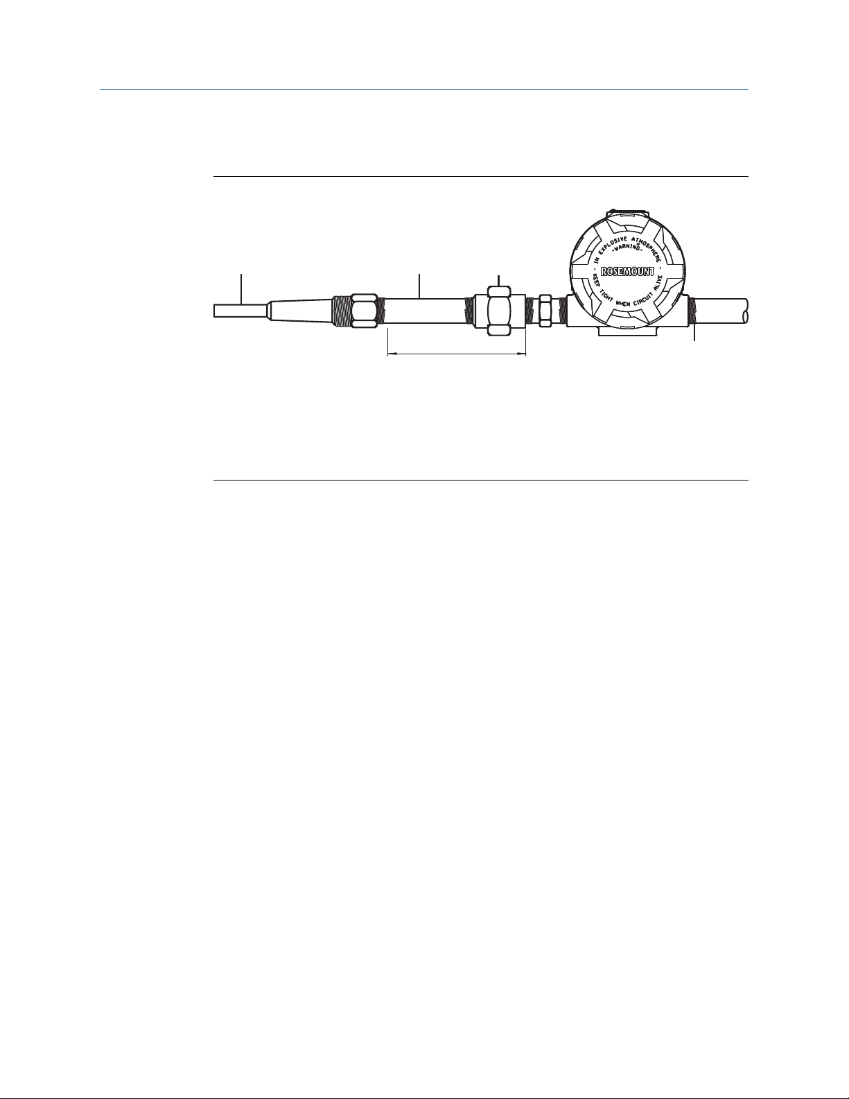
2.4.1 Typical North American installation
Figure 2-6: Typical Direct-Mounted Configuration
A. Thermowell
B. Extension (nipple)
C. Union or coupling
D. Conduit for field wiring (dc power)
E. Extension fitting length
Procedure
1. Mount the thermowell to the process container wall.
2. Install and tighten thermowells.
3. Perform a leak check.
4. Attach any necessary unions, couplings, and extension fittings. Seal the fitting
threads with an approved thread sealant, such as silicone or PTFE tape (if required).
5. Screw the sensor into the thermowell or directly into the process (depending on
installation requirements).
6. Verify all sealing requirements.
7. Attach the transmitter to the thermowell/sensor assembly. Seal all threads with an
approved thread sealant, such as silicone or PTFE tape (if required).
8. Install field wiring conduit into the open transmitter conduit entry (for remote
mounting) and feed wires into the transmitter housing.
9. Pull the field wiring leads into the terminal side of the housing.
10. Attach the sensor leads to the transmitter sensor terminals.
The wiring diagram is located inside the housing cover.
11. Attach and tighten both transmitter covers.
18 Rosemount 3144P
A
B
C
D
E
Reference Manual
00809-0100-4021 December 2019
Installation
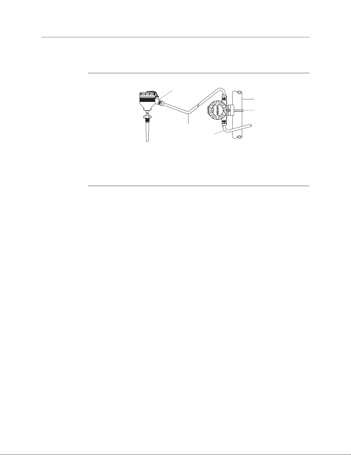
2.4.2 Typical European installation
Figure 2-7: Typical Remote-Mounted Configuration with Cable Glands
A. Cable gland
B. Shielded cable from sensor to transmitter
C. Shielded cable from transmitter to control room
D. 2-in. (50 mm) pipe
E. B4 mounting bracket
2.4.3
Procedure
1. Mount the thermowell to the process container wall.
2. Install and tighten thermowells.
3. Perform a leak check.
4. Attach a connection head to the thermowell.
5. Insert sensor into the thermowell and wire the sensor to the connection head.
The wiring diagram is located inside the connection head.
6. Mount the transmitter to a 2-in. (50 mm) pipe or a panel using one of the optional
mounting brackets.
7. Attach cable glands to the shielded cable running from the connection head to the
transmitter conduit entry.
8. Run the shielded cable from the opposite conduit entry on the transmitter back to
the control room.
9. Insert shielded cable leads through the cable entries into the connection head/
transmitter. Connect and tighten cable glands.
10. Connect the shielded cable leads to the connection head terminals (located inside
the connection head) and to the sensor wiring terminals (located inside the
transmitter housing).
Rosemount X-well installation
Rosemount X-well™ Technology is for temperature monitoring applications and is not
intended for control or safety applications. It is available in the Rosemount 3144P
Temperature Transmitter in a factory assembled direct mount configuration with a
Rosemount 0085 Pipe Clamp Sensor. It cannot be used in a remote mount configuration.
Rosemount X-well Technology will only work as specified with factory supplied and
Reference Manual 19
assembled Rosemount 0085 Pipe Clamp silver tipped single element sensor with an 80
mm extension length. It will not work as specified if used with other sensors. Installation
Installation
December 2019 00809-0100-4021
and use of incorrect sensor will result in inaccurate process temperature calculations. It is
extremely important that the above requirements and installation steps below are
followed to ensure that Rosemount X-well Technology works as specified.
In general, pipe clamp sensor installation best practices shall be followed. See Rosemount
0085 Pipe Clamp Sensor Quick Start Guide with Rosemount X-well Technology specific
requirements noted:
1. Mount transmitter directly on pipe clamp sensor in order for Rosemount X-well
Technology to properly function.
2. Install assembly away from dynamic external temperature sources such as a boiler
or heat tracing.
3. Ensure for the pipe clamp sensor tip to make direct contact with the pipe surface for
Rosemount X-well Technology. Moisture build-up between sensor and pipe surface,
or sensor hang-up in assembly can cause inaccurate process temperature
calculations. Refer to installation best practices in Rosemount 0085 Pipe Clamp
Sensor Quick Start Guide to ensure proper sensor to pipe surface contact.
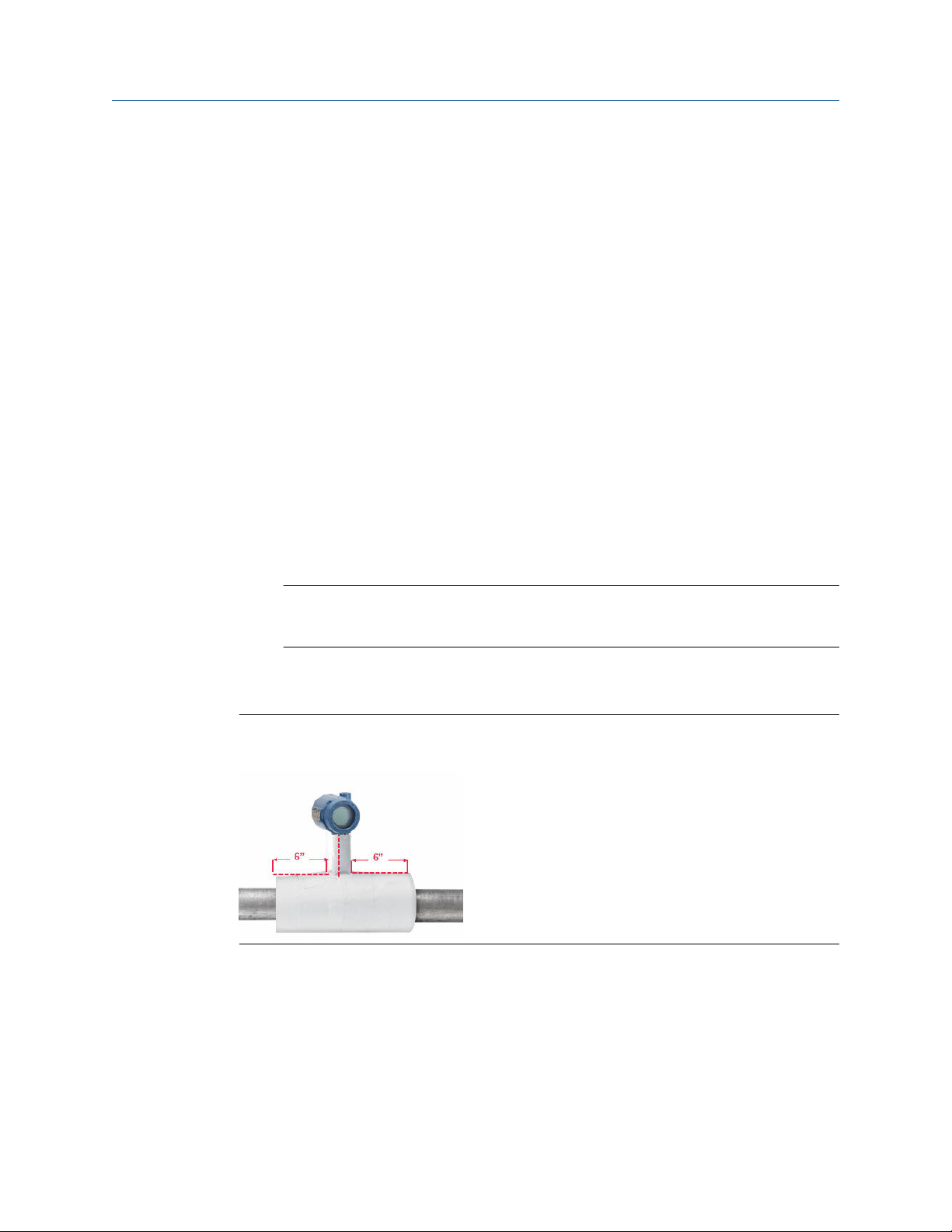
4. Insulation ½-in. thick minimum with a R-value of > 0.42 m² × K/W) is required over
the sensor clamp assembly and sensor extension up to transmitter head to prevent
heat loss. Apply a minimum of six inches of insulation on each side of the pipe
clamp sensor. Care should be taken to minimize air gaps between insulation and
pipe.
Reference Manual
2.4.4
Note
DO NOT apply insulation over transmitter head as it will result in longer response
times and may damage transmitter electronics.
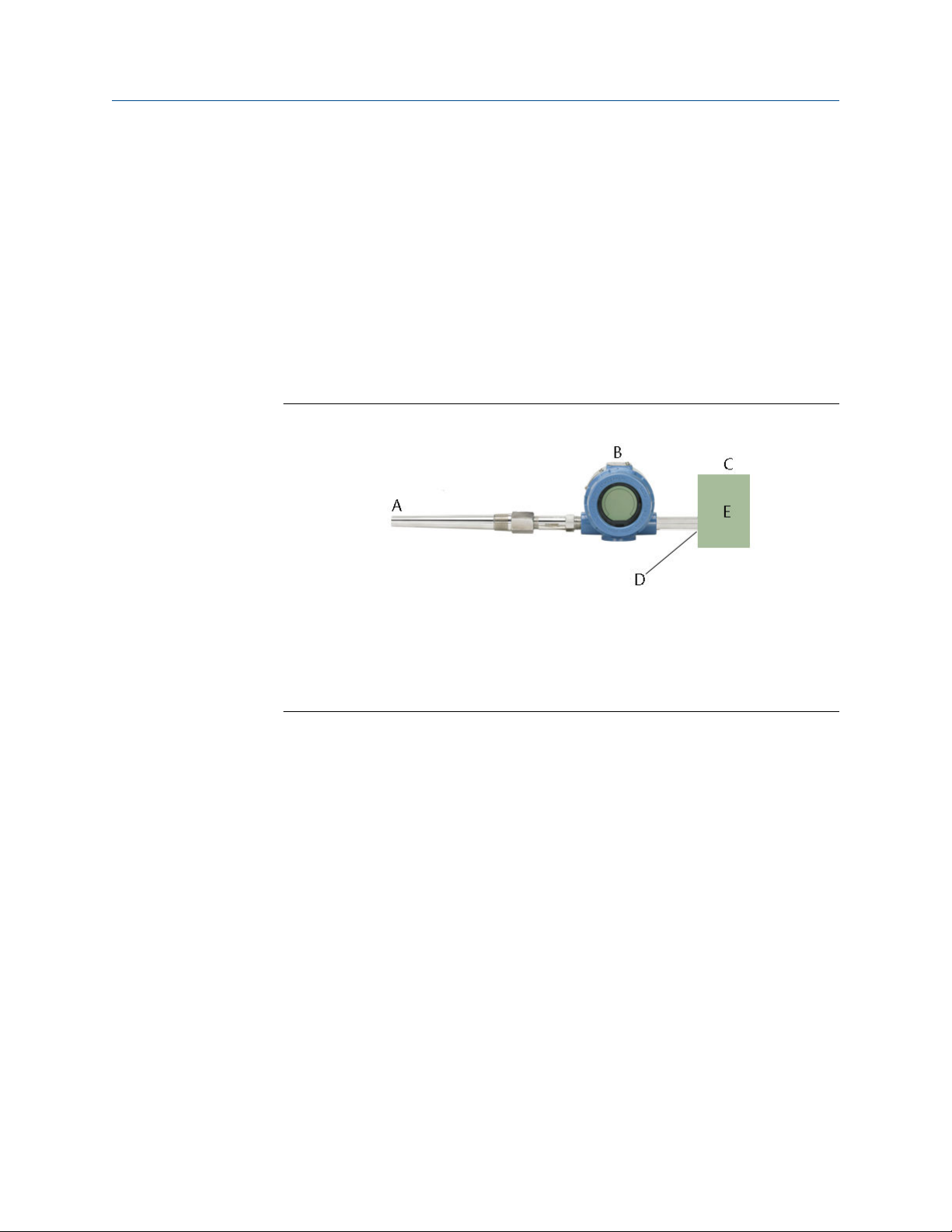
5. Although it will come factory configured as such, ensure that pipe clamp RTD
sensor is assembled in 4-wire configuration.
Figure 2-8: Rosemount 3144P Transmitter with Rosemount X-well Technology
Installation
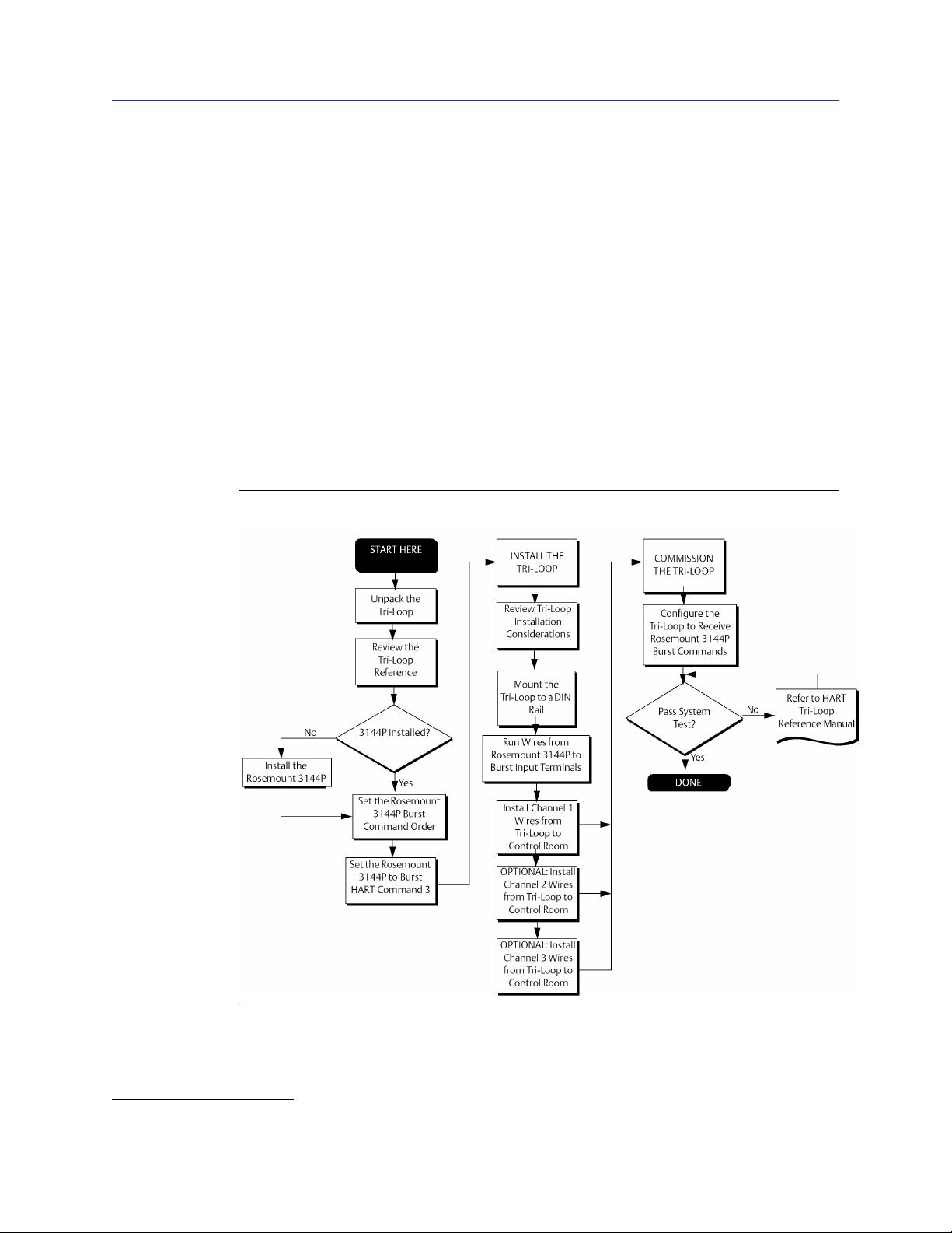
Install Rosemount X-well in conjunction with a Rosemount 333 Tri-Loop (HART/4–20 mA only)
Use the dual-sensor option Rosemount 3144P Transmitter that is operating with two
sensors in conjunction with a Rosemount 333 HART Tri-Loop™ HART-to-Analog Signal
Converter to acquire an independent 4–20 mA analog output signal for each sensor input.
20 Rosemount 3144P
Reference Manual Installation
00809-0100-4021 December 2019
The transmitter can be configured to output four of the six following digital process
variables:
• Sensor 1
• Sensor 2
• Differential temperature
• Average temperature
• First good temperature
• Transmitter terminal temperature
• Surface temperature (Rosemount X-well only)
The HART Tri-Loop reads the digital signal and outputs any or all of these variables into as
many as three separate 4–20 mA analog channels.
Refer to Figure 2-9 for basic installation information. Refer to the Rosemount 333 HARTto-Analog Reference Manual signal converter for complete installation information.
Figure 2-9: HART Tri-Loop Installation Flowchart
(1)
(1) See Use with the HART Tri-Loop for configuration information.
Reference Manual 21

Installation Reference Manual
December 2019 00809-0100-4021
2.4.5 LCD display
Transmitters ordered with the LCD display option (code M5) are shipped with the LCD
display installed. After-market installation of the LCD display on a conventional transmitter
requires a small instrument screwdriver and the LCD display kit, which includes:
• LCD display assembly
• Extended cover with cover O-ring in place
• Captive screws (quantity 2)
• 10-pin interconnection header
To install the LCD display:
Procedure
1. If the transmitter is installed in a loop, set the loop to manual (HART)/out-of-service
(FOUNDATION Fieldbus) mode and disconnect the power.
2. Remove the housing cover from the electronics side of the transmitter. Do not
remove the transmitter covers in explosive atmospheres with a live circuit.
3. Ensure that the transmitter write protect switch is set to the Off position. If
transmitter security is On, the transmitter cannot be configured to recognize the
LCD display. If security On is desired, configure the transmitter for the LCD display,
and then install the meter.
4. Insert the interconnection header in the 10-pin socket on the face of the electronics
module. Insert the pins into the electronics LCD display interface.
5. The meter can be rotated in 90-degree increments for easy viewing. Position one of
the four 10-pin sockets on the back of the meter to accept the interconnection
header.
6. Attach the LCD display assembly to the interconnection pins, then thread and
tighten the LCD display screws into the holes on the electronics module.
7. Attach the extended cover; tighten at least one-third turn after the O-ring contacts
the transmitter housing. Both transmitter covers must be fully engaged to meet
explosion proof requirements.
8. Apply power and set the loop to automatic (HART)/in-service (FOUNDATION Fieldbus)
mode.
Once the LCD display is installed, configure the transmitter to recognize the meter
option. Refer to LCD display options or LCD display transducer block (index number
1200) (FOUNDATION Fieldbus).
Note
Observe the following LCD display temperature limits:
Operating: –40 to 185 °F (–40 to 85 °C)
Storage: –76 to 185 °F (–60 to 85 °C)
22 Rosemount 3144P
A
B
C
D
E
F
G
H
Reference Manual
00809-0100-4021 December 2019
Installation
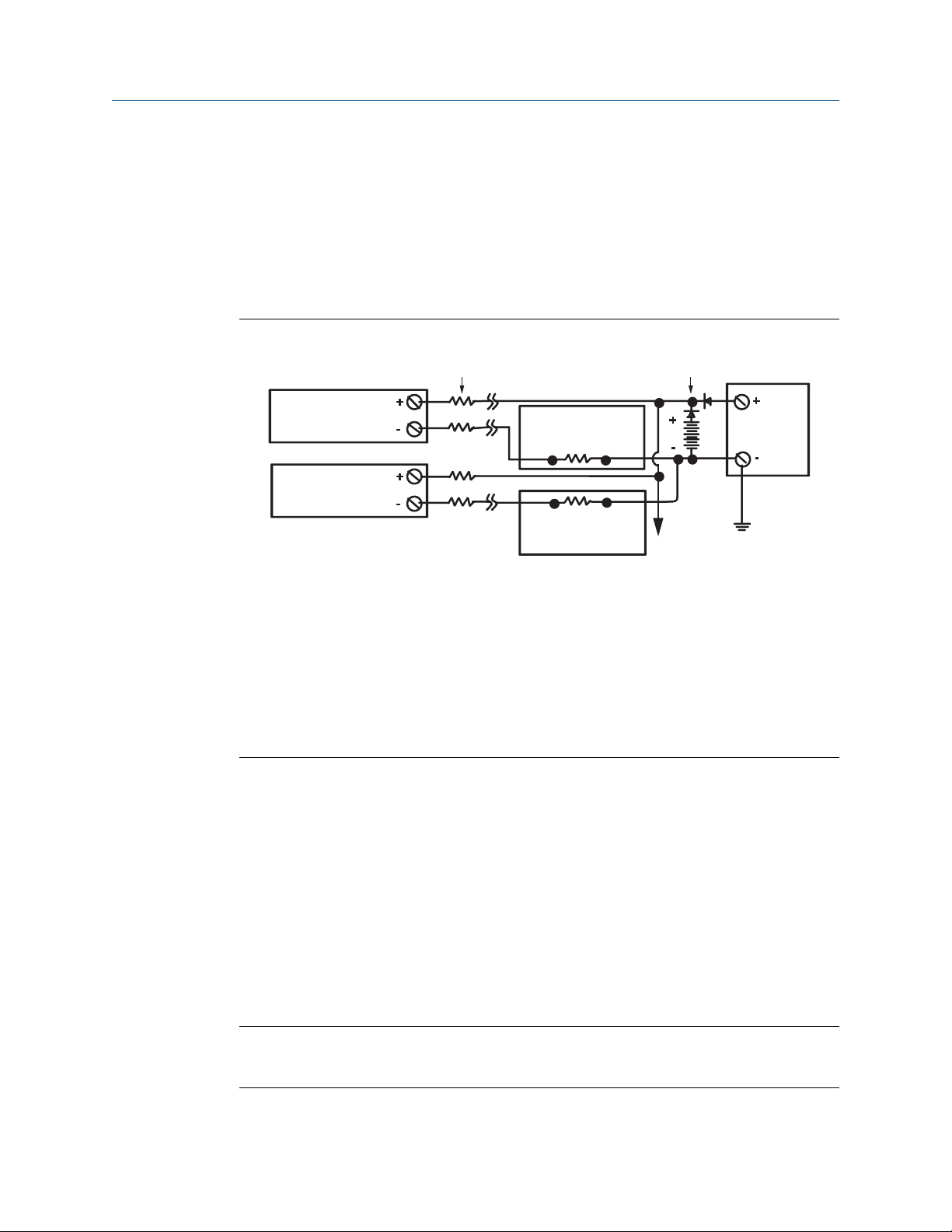
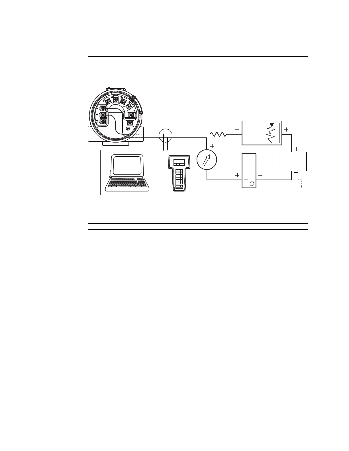
2.4.6 Multichannel installation (HART/4–20 mA only)
Several transmitters can be connected to a single master power supply (see figure below).
In this case, the system may be grounded only at the negative power supply terminal. In
multichannel installations, where several transmitters depend on one power supply and
the loss of all transmitters would cause operational problems, consider an uninterrupted
power supply or a back-up battery. The diodes shown in Figure 2-10 prevent unwanted
charging or discharging of the back-up battery.
Figure 2-10: Multichannel Installations
Between 250 and 1100 Ω If no load resistor
A. Transmitter 1
B. Transmitter 2
C. R
Lead
D. Readout or controller 1
E. Readout or controller 2
F. Battery backup
G. Power supply dc
2.5 Wiring
2.5.1 HART/4–20 mA
Field wiring
The power to the transmitter is supplied over the signal wiring. Signal wiring does not
need to be shielded, but twisted pairs should be used for best results. Do not run
unshielded signal wiring in conduit or open trays with power wiring or near heavy electrical
equipment because high voltage may be present on the leads and may cause an electrical
shock.
Note
Do not apply high voltage (e.g., AC line voltage) to the power or sensor terminals, since
high voltage can damage the unit.
To wire the transmitter for power:
Reference Manual 23
“-”
“+”
Test
A
B
B
A
“+”
“-”
Installation Reference Manual
December 2019 00809-0100-4021
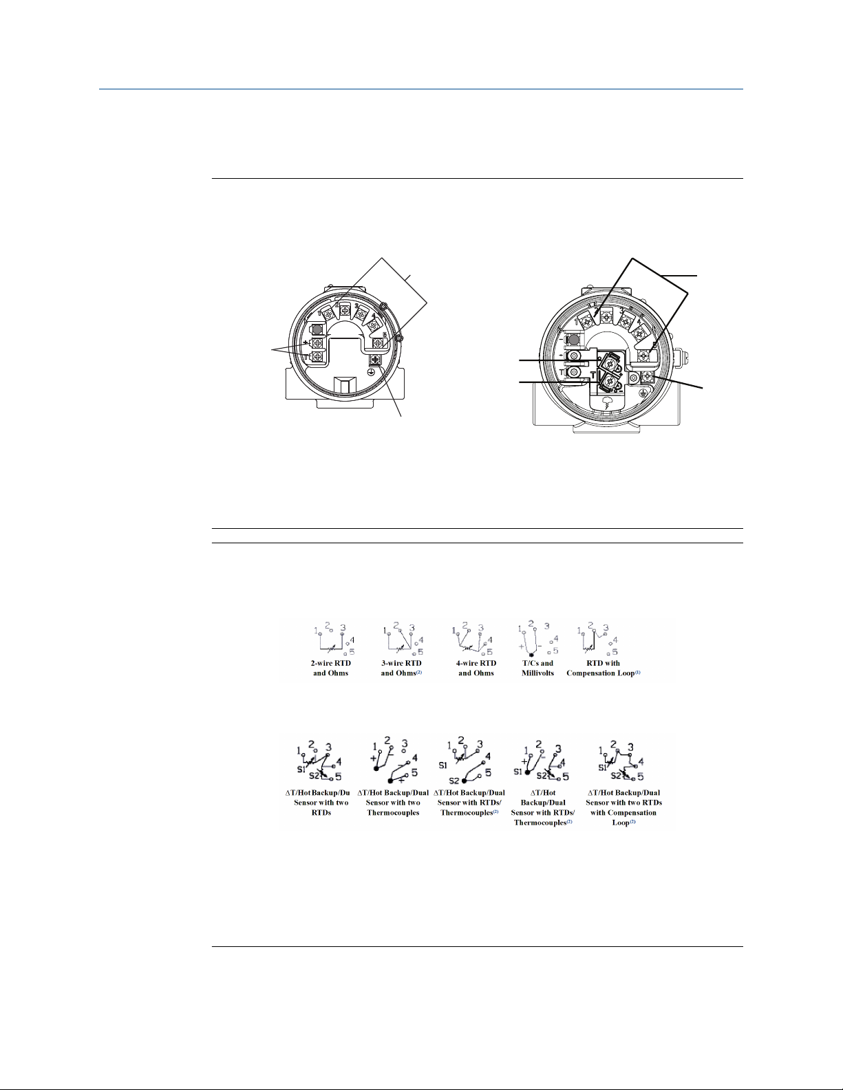
Figure 2-11: Transmitter Terminal Block Wiring Connection
Wiring connection
Wiring connection
(with “T1” integral transient protection
option)
A. Sensor terminals (1–5)
B. Ground
Figure 2-12: Sensor Wiring Diagram for HART/4–20 mA
Single-sensor connections
Dual-sensor connections
(1) (2)
(1) Transmitter must be configured for a 3-wire RTD in order to recognize an RTD with a
compensation loop.
(2) Emerson provides 4-wire sensors for all single-element RTDs. Use these RTDs in 2- or 3-wire
24 Rosemount 3144P
configurations by leaving the unneeded leads disconnected and insulated with electrical tape.

Reference Manual Installation
00809-0100-4021 December 2019
Procedure
1. Remove the transmitter covers.
Do not remove the transmitter covers in an explosive atmosphere when the circuit
is live.
2. Connect the positive power lead to the terminal marked “+” and the negative
power lead to the terminal marked “–” as shown in Figure 2-11.
Crimped lugs are recommended when wiring to screw terminals.
3. Tighten the terminal screws to ensure good contact is made. No additional power
wiring is required.
4. Replace the transmitter covers making sure both transmitter covers are fully
engaged to meet explosion-proof requirements.
Power/current loop connections
Use copper wire of a sufficient size to ensure that the voltage across the transmitter power
terminals does not go below 12.0 Vdc.
1. Connect the current signal leads as shown in Figure 2-13.
2. Recheck the polarity and connections.
3. Turn the power ON.
For information about multichannel installations, refer to Multichannel installation
(HART/4–20 mA only).
Note
Do not connect the power/signal wiring to the test terminal. The voltage present on the
power/signal leads may burn out the reverse-polarity protection diode built into the test
terminal. If the test terminal’s reverse polarity protection diode is burned out by the
incorrect power/signal wiring, the transmitter can still be operated by jumping the current
from the test terminal to the “–” terminal. See Test terminal (HART/4–20 mA only) for use
of the terminal.
Reference Manual 25
A
C
or*
B
Installation Reference Manual
December 2019 00809-0100-4021
Figure 2-13: Connecting a Field Communicator to a Transmitter Loop (HART/4–20
mA)
A. Power/signal terminals
B. 250 ≤ RL ≤ 1100
C. Power supply
Note
The signal wire may be grounded at any point or left ungrounded.
Note
AMS Device Manager software or a Field Communicator can be connected at any
termination point in the signal loop. The signal loop must have between 250 and 1100
ohms load for communications.
26 Rosemount 3144P
A
C
B
B
C
A
Reference Manual Installation
00809-0100-4021 December 2019
2.6 Foundation Fieldbus
Figure 2-14: Transmitter Terminal Block
Wiring connection Wiring connection
(with “T1” integral transient protection option)
A. Sensor terminals (1–5)
B. Power terminals
C. Ground
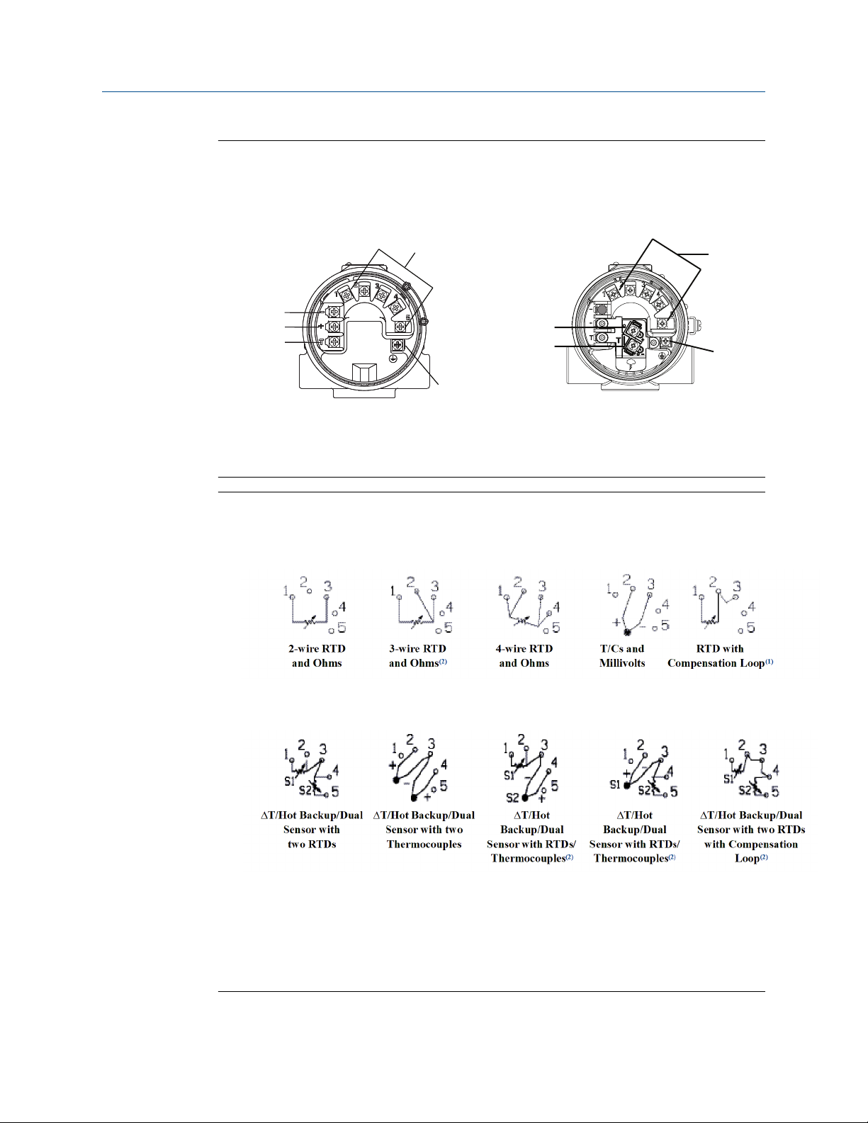
Figure 2-15: Sensor Wiring Diagram for FOUNDATION Fieldbus
Single-sensor connections
Dual-sensor connections
(1) (2)
(1) Transmitter must be configured for a 3-wire RTD in order to recognize an RTD with a
compensation loop.
(2) Emerson provides 4-wire sensors for all single-element RTDs. Use these RTDs in 2- or 3-wire
Reference Manual 27
configurations by leaving the unneeded leads disconnected and insulated with electrical tape.

Installation
December 2019 00809-0100-4021
RTD or ohm inputs
If the transmitter is mounted remotely from a 3- or 4-wire RTD, it will operate within
specifications, without recalibration, for lead wire resistances of up to 60 ohms per lead
(equivalent to 1,000 ft. of 20 AWG wire). In this case, the leads between the RTD and
transmitter should be shielded. If using only two leads (or a compensation loop lead wire
configuration), both RTD leads are in series with the sensor element, so significant errors
can occur if the lead lengths exceed one foot of 20 AWG wire. For longer runs, attach a
third or fourth lead as described above. To eliminate 2-wire lead resistance error, the 2wire offset command can be used. This allows the user to input the measured lead wire
resistance, resulting in the transmitter adjusting the temperature to correct the error.
When using Rosemount X-well Technology, the Rosemount 3144P Temperature
Transmitter is required to be assembled to a Rosemount 0085 Pipe Clamp RTD Sensor in a
direct mount 4-wire configuration. It can be changed to 3- or 2-wired configuration, if
required, in the field.
Thermocouple or millivolt inputs
For direct-mount applications, connect the thermocouple directly to the transmitter. If
mounting the transmitter remotely from the sensor, use appropriate thermocouple
extension wire. Make connections for millivolt inputs with copper wire. Use shielding for
long runs of wire.
Reference Manual
Note
For HART transmitters, the use of two grounded thermocouples with a dual option
transmitter is not recommended. For applications in which the use of two thermocouples
is desired, connect either two ungrounded thermocouples, one grounded and one
ungrounded thermocouple, or one dual element thermocouple.
2.7 Power supply
HART
An external power supply is required to operate the transmitter (not included). The input
voltage range of the transmitter is 12 to 42.4 Vdc. This is the power required across the
transmitter power terminals. The power terminals are rated to 42.4 Vdc. With 250 ohms
of resistance in the loop, the transmitter requires a minimum of 18.1 Vdc for
communication.
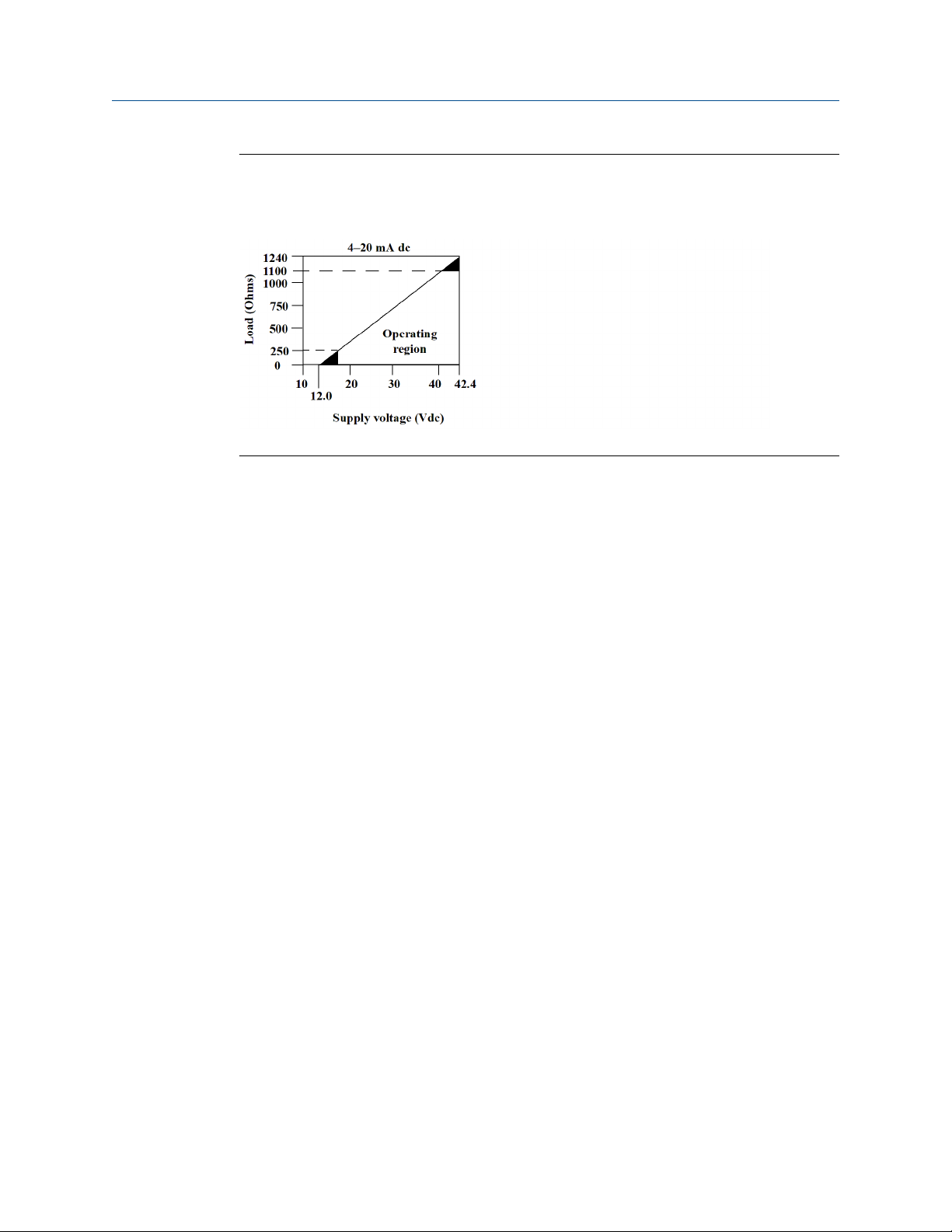
The power supplied to the transmitter is determined by the total loop resistance and
should not drop below the lift-off voltage. The lift-off voltage is the minimum supply
voltage required for any given total loop resistance. See Figure 2-16 to determine the
required supply voltage. If the power drops below the lift-off voltage while the transmitter
is being configured, the transmitter may output incorrect information.
The dc power supply should provide power with less than two percent ripple. The total
resistance load is the sum of the resistance of the signal leads and the load resistance of
any controller, indicator, or related piece of equipment in the loop. Note that the
resistance of intrinsic safety barriers, if used, must be included.
Note
Permanent damage to the transmitter could result if the voltage drops below 12.0 Vdc at
the power terminals, when changing transmitter configuration parameters.
28 Rosemount 3144P
Reference Manual
00809-0100-4021 December 2019
Figure 2-16: Load Limits
Maximum load = 40.8 × (Supply voltage–12.0)
FOUNDATION Fieldbus
Powered over FOUNDATION Fieldbus with standard Fieldbus power supplies, the transmitter
operates between 9.0 and 32.0 Vdc, 11 mA maximum. Transmitter power terminals are
rated to 42.4 Vdc.
Installation
The power terminals on the transmitter are polarity insensitive.
2.7.1
Surges/transients
The transmitter will withstand electrical transients of the energy level usually encountered
in static discharges or induced switching; however, high-voltage transients, such as those
induced in wiring from nearby lightning strikes, can damage both the transmitter and the
sensor.
The integral transient protection terminal block (option code T1) protects against highvoltage transients. The integral transient protection terminal block is available as an
ordered option, or as an accessory.
2.8 Grounding
Sensor shielding
The currents in the leads induced by electromagnetic interference can be reduced by
shielding. Shielding carries the current to ground and away from the leads and electronics.
If the ends of the shields are adequately grounded, only a small amount of current will
actually enter the transmitter.
If the ends of the shield are left ungrounded, voltage is created between the shield and the
transmitter housing and also between the shield and earth at the element end. The
transmitter may not be able to compensate for this voltage, causing it to lose
communication and/or go into alarm. Instead of the shield carrying the currents away
from the transmitter, the currents will now flow through the sensor leads into the
transmitter circuitry where it will interfere with the circuit operation.
Reference Manual 29
Installation Reference Manual
December 2019 00809-0100-4021
2.8.1 Ungrounded thermocouple, mV, and RTD/ohm inputs
Option 1: Recommended for ungrounded transmitter housing
1. Connect the signal wiring shield to the sensor wiring shield.
2. Ensure the two shields are tied together and electrically isolated from the
transmitter housing.
3. Ground the shield at the power supply end only.
4. Ensure the shield at the sensor is electrically isolated from the surrounding fixtures
that may be grounded.
a. Connect shields together, electrically isolated from the transmitter.
A. Sensor wires
B. Transmitter
C. 4-20 mA loop
D. Shield ground point
E. DCS
Option 2: Recommended for grounded transmitter housing
1. Ground the transmitter housing then connect the sensor wiring shield to the
transmitter housing (see Transmitter housing).
2. Ensure the shield at the sensor end is electrically isolated from surrounding fixtures
that may be grounded.
3. Ground the signal wiring shield at the power supply end.
30 Rosemount 3144P
 Loading...