

Rosemount 3095 Product Manual
Model 3095
™
Multivariable
Level Controller
00809-0100-4741
English
Rev. AA

Product Manual
1Model 3095 Multivariable
™
Level Controller
NOTICE
Read this manual before working with the prod uc t. For perso nal and system
safety, and for optimum product performance, make sure you thoroughly
understand the conten ts before installing, using, or maintaining this product.
Within the United States, Rosemount Inc. ha s two tol l-free assistance numbers.
Customer Central: 1-800-999-9307 (
Technical support, quoting, and order-related questions.
North American 1-800-654-7768 (
Response Center: Equipment service needs.
For equipment s ervice or s upport n eeds outs ide the United State s, cont act your
local Rosemount representative.
7:00 a.m. to 7:00 p.m. CST)
24 hours a day – Includes Canada)
Rosemount Inc.
8200 Market Boulevard
Chanhassen, MN 55317 USA
Tel 1-800-999-9307
Telex 4310012
Fax (612) 949-7001
© 1998 Rosemount, Inc.
http://www.rosemount.com
The products described in this document are NOT designed for nuclearqualified applications.
Using non-nuclear qua lifi ed products in applications that require nuclearqualified hardware or products may cause inaccurate readings.
For information on Rosemount nucle ar-qualified products, contact you r local
Rosemount Sales Representative.
SNF-0004
Rosemount and the Rosemount logotype are registered trademarks of Rosemount Inc.
Coplanar and Multivariable are trademarks of Rosemount Inc.
Plantweb is a mark of the Fisher-Rosemount group of companies.
HART is a registered trademark of the HART Communica tion Found atio n.
Hastelloy C-276 is a registered trademark of Cabo t Corp.
Microsoft and Windows are registered trademarks of Microsoft Corp.
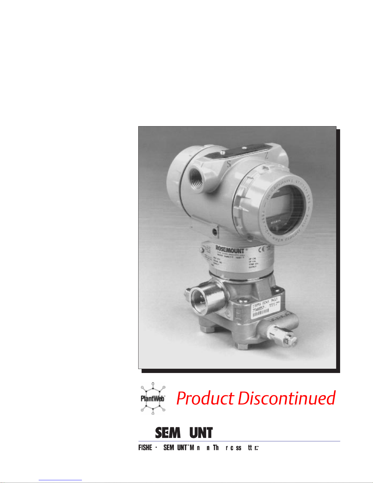
Cover Photo: 3095LC01
Fisher-Rosemount satisfie s all ob liga tio n s comin g from legisla tio n
Fisher-Rosemount satisfies all obligations coming from legislation
to harmonize product requi r em en ts in th e Eur opean Union.
to harmonize product requi r em en ts i n th e European Union.
T
N
I
E
D
R
P
IN
U.
A.
S.


Table of Contents
IMPORTANT
Procedures and instructions in this manual may require special precautions to
ensure the safety of the personnel performing the operations. Information that
raises potential safety issues is indicated by a warning symbol ( ). Refer to the
safety messages listed at the beginning of each section before performin g
an operation preceded by this symbol.
SECTION 1
Introduction
SECTION 2
Level Controller Overview
and Installation
Using This Manual . . . . . . . . . . . . . . . . . . . . . . . . . . . . . . . . . . . . . . . 1-1
Safety Messages . . . . . . . . . . . . . . . . . . . . . . . . . . . . . . . . . . . . . . . . . 1-1
Safety Messages . . . . . . . . . . . . . . . . . . . . . . . . . . . . . . . . . . . . . . . . . 2-1
Level Controller Overview . . . . . . . . . . . . . . . . . . . . . . . . . . . . . . . . . 2-2
Before you Begin . . . . . . . . . . . . . . . . . . . . . . . . . . . . . . . . . . . . . . . . . 2-4
Unpacking the Level Controller . . . . . . . . . . . . . . . . . . . . . . . . . . . . 2-5
Becoming Familiar with the Level Controller . . . . . . . . . . . . . . . . . 2-5
Bench Configuration . . . . . . . . . . . . . . . . . . . . . . . . . . . . . . . . . . . . . . 2-7
Failure Mode Alarm vs. Saturation Output Values . . . . . . . . . . 2-7
Write Protect and Failure Mode Alarm Jumpers . . . . . . . . . . . . 2-7
General Installation Considerations . . . . . . . . . . . . . . . . . . . . . . . . . 2-9
Mechanical Considerations . . . . . . . . . . . . . . . . . . . . . . . . . . . . . . . . 2-10
Mounting Considerations . . . . . . . . . . . . . . . . . . . . . . . . . . . . . . 2-10
Bolt Installation Guidelines . . . . . . . . . . . . . . . . . . . . . . . . . . . . 2-10
Example Installations . . . . . . . . . . . . . . . . . . . . . . . . . . . . . . . . . . . . 2-13
Open Tanks . . . . . . . . . . . . . . . . . . . . . . . . . . . . . . . . . . . . . . . . . . 2-13
Open Tanks with Bubbler . . . . . . . . . . . . . . . . . . . . . . . . . . . . . . 2-13
Closed Tanks with Dry Leg . . . . . . . . . . . . . . . . . . . . . . . . . . . . . 2-13
Closed Tanks with Wet Leg . . . . . . . . . . . . . . . . . . . . . . . . . . . . . 2-13
Tap Considerations . . . . . . . . . . . . . . . . . . . . . . . . . . . . . . . . . . . . . . . 2-15
Impulse Piping . . . . . . . . . . . . . . . . . . . . . . . . . . . . . . . . . . . . . . . 2-15
Diaphragm Seals . . . . . . . . . . . . . . . . . . . . . . . . . . . . . . . . . . . . . 2-15
Environmental Considerations . . . . . . . . . . . . . . . . . . . . . . . . . . . . . 2-16
Access Requirements . . . . . . . . . . . . . . . . . . . . . . . . . . . . . . . . . . 2-16
Process Considerations . . . . . . . . . . . . . . . . . . . . . . . . . . . . . . . . 2-17
Electrical Considerations . . . . . . . . . . . . . . . . . . . . . . . . . . . . . . . . . . 2-18
Field Installation Procedure . . . . . . . . . . . . . . . . . . . . . . . . . . . . . . . 2-19
Field Installation Equipment . . . . . . . . . . . . . . . . . . . . . . . . . . . 2-19
Review Installation Considerations . . . . . . . . . . . . . . . . . . . . . . 2-19
Mount Controller and Install Bolts . . . . . . . . . . . . . . . . . . . . . . . 2-19
Make Process Connections . . . . . . . . . . . . . . . . . . . . . . . . . . . . . 2-19
Install RTD Assembly . . . . . . . . . . . . . . . . . . . . . . . . . . . . . . . . . 2-20
Check for Leaks . . . . . . . . . . . . . . . . . . . . . . . . . . . . . . . . . . . . . . 2-21
Field Wiring (Power and Signal) . . . . . . . . . . . . . . . . . . . . . . . . . 2-21
Install Field Wiring Grounds . . . . . . . . . . . . . . . . . . . . . . . . . . . 2-22
Replace Cover . . . . . . . . . . . . . . . . . . . . . . . . . . . . . . . . . . . . . . . . 2-23
Calibration . . . . . . . . . . . . . . . . . . . . . . . . . . . . . . . . . . . . . . . . . . . . . 2-23
v

SECTION 3
Level Controller Operation
Introduction . . . . . . . . . . . . . . . . . . . . . . . . . . . . . . . . . . . . . . . . . . . . . 3-1
Level Variables and Values . . . . . . . . . . . . . . . . . . . . . . . . . . . . . . . . . 3-1
Level Controller Sensor . . . . . . . . . . . . . . . . . . . . . . . . . . . . . . . . . . . 3-2
PID Controller Description and Details . . . . . . . . . . . . . . . . . . . . . . 3-3
AutoTuning . . . . . . . . . . . . . . . . . . . . . . . . . . . . . . . . . . . . . . . . . . . . . 3-4
Why Autotune? . . . . . . . . . . . . . . . . . . . . . . . . . . . . . . . . . . . . . . . 3-5
Autotuner Operation . . . . . . . . . . . . . . . . . . . . . . . . . . . . . . . . . . 3-6
Alpha Adjustment for Tuning . . . . . . . . . . . . . . . . . . . . . . . . . . . 3-6
Adaptive Bias Control . . . . . . . . . . . . . . . . . . . . . . . . . . . . . . . . . . . . . 3-7
When to Use Adaptive Bias Control . . . . . . . . . . . . . . . . . . . . . . 3-7
How ABC Works . . . . . . . . . . . . . . . . . . . . . . . . . . . . . . . . . . . . . . 3-7
Local Operator Interface . . . . . . . . . . . . . . . . . . . . . . . . . . . . . . . . . . 3-8
Mode Shed Option . . . . . . . . . . . . . . . . . . . . . . . . . . . . . . . . . . . . . . . . 3-8
SECTION 4
Level Controller
Configuration
Configuration Overview . . . . . . . . . . . . . . . . . . . . . . . . . . . . . . . . . . . 4-1
Set Up the Level Calculation . . . . . . . . . . . . . . . . . . . . . . . . . . . . . . . 4-2
Place Controller into Out-of-Service (OOS) Mode . . . . . . . . . . . 4-2
Set Density . . . . . . . . . . . . . . . . . . . . . . . . . . . . . . . . . . . . . . . . . . 4-2
Set Level Units . . . . . . . . . . . . . . . . . . . . . . . . . . . . . . . . . . . . . . . 4-2
Set Controller Height . . . . . . . . . . . . . . . . . . . . . . . . . . . . . . . . . . 4-4
Additional Options . . . . . . . . . . . . . . . . . . . . . . . . . . . . . . . . . . . . 4-4
Configure the Controller . . . . . . . . . . . . . . . . . . . . . . . . . . . . . . . . . . . 4-5
Set Range Values . . . . . . . . . . . . . . . . . . . . . . . . . . . . . . . . . . . . . 4-5
Set Control Type . . . . . . . . . . . . . . . . . . . . . . . . . . . . . . . . . . . . . . 4-5
Set Control Action (Direct, Reverse) . . . . . . . . . . . . . . . . . . . . . . 4-5
Adaptive Bias Control (ABC) Settings . . . . . . . . . . . . . . . . . . . . 4-6
Set Power-Up Output . . . . . . . . . . . . . . . . . . . . . . . . . . . . . . . . . . 4-6
Set Mode Shed Options (Failure Condition) . . . . . . . . . . . . . . . . 4-7
Set Manual Output . . . . . . . . . . . . . . . . . . . . . . . . . . . . . . . . . . . . 4-7
Set Auto Output Limits . . . . . . . . . . . . . . . . . . . . . . . . . . . . . . . . 4-8
Choose Setpoint Values . . . . . . . . . . . . . . . . . . . . . . . . . . . . . . . . 4-8
Additional Options . . . . . . . . . . . . . . . . . . . . . . . . . . . . . . . . . . . . 4-8
Perform a Level Trim . . . . . . . . . . . . . . . . . . . . . . . . . . . . . . . . . . . . .4-10
Trim Level . . . . . . . . . . . . . . . . . . . . . . . . . . . . . . . . . . . . . . . . . . . 4-10
Level Trim Recall . . . . . . . . . . . . . . . . . . . . . . . . . . . . . . . . . . . . .4-10
Tune the Loop . . . . . . . . . . . . . . . . . . . . . . . . . . . . . . . . . . . . . . . . . . . 4-11
Set Target Mode . . . . . . . . . . . . . . . . . . . . . . . . . . . . . . . . . . . . . . 4-11
Set Control Tuning . . . . . . . . . . . . . . . . . . . . . . . . . . . . . . . . . . . . 4-11
Autotuner (Optional) . . . . . . . . . . . . . . . . . . . . . . . . . . . . . . . . . .4-12
vi

SECTION 5
Troubleshooting
and Maintenance
Safety Messages . . . . . . . . . . . . . . . . . . . . . . . . . . . . . . . . . . . . . . . . . 5-1
Level Controller Troubleshooting . . . . . . . . . . . . . . . . . . . . . . . . . . . . 5-2
Communication Problems . . . . . . . . . . . . . . . . . . . . . . . . . . . . . . 5-2
Interpreting Level Controller Alarms and Error Conditions . . . 5-3
Disassembly Procedures . . . . . . . . . . . . . . . . . . . . . . . . . . . . . . . . . . . 5-10
Process Sensor Body . . . . . . . . . . . . . . . . . . . . . . . . . . . . . . . . . . .5-10
Electrical Housing . . . . . . . . . . . . . . . . . . . . . . . . . . . . . . . . . . . . 5-11
Remove the Electronics Board . . . . . . . . . . . . . . . . . . . . . . . . . . . 5-11
Remove the Sensor Module from the Electronics Housing . . . .5-13
Reassembly Procedures . . . . . . . . . . . . . . . . . . . . . . . . . . . . . . . . . . . 5-14
Attach the Sensor Module to the Electronics Housing . . . . . . . . 5-14
Attach the Electronics Board . . . . . . . . . . . . . . . . . . . . . . . . . . . .5-15
Reassemble the Process Sensor Body . . . . . . . . . . . . . . . . . . . . .5-16
Return of Materials . . . . . . . . . . . . . . . . . . . . . . . . . . . . . . . . . . . . . . .5-17
SECTION 6
Level Controller
Specifications and
Reference Data
APPENDIX A
HART Communicator
APPENDIX B
Level Controller Accessories and Options
Functional Specifications . . . . . . . . . . . . . . . . . . . . . . . . . . . . . . . . . . 6-1
Performance Specifications . . . . . . . . . . . . . . . . . . . . . . . . . . . . . . . . 6-4
Physical Specifications . . . . . . . . . . . . . . . . . . . . . . . . . . . . . . . . . . . . 6-5
Ordering Information . . . . . . . . . . . . . . . . . . . . . . . . . . . . . . . . . . . . . 6-6
Options . . . . . . . . . . . . . . . . . . . . . . . . . . . . . . . . . . . . . . . . . . . . . 6-7
Accessories . . . . . . . . . . . . . . . . . . . . . . . . . . . . . . . . . . . . . . . . . . 6-8
Introduction . . . . . . . . . . . . . . . . . . . . . . . . . . . . . . . . . . . . . . . . . . . . . A-1
Safety Messages . . . . . . . . . . . . . . . . . . . . . . . . . . . . . . . . . . . . . . . . . A-1
Connections and hardware . . . . . . . . . . . . . . . . . . . . . . . . . . . . . . . . . A-4
Communicator Keys . . . . . . . . . . . . . . . . . . . . . . . . . . . . . . . . . . . . . . A-6
Action Keys . . . . . . . . . . . . . . . . . . . . . . . . . . . . . . . . . . . . . . . . . . A-6
Function Keys . . . . . . . . . . . . . . . . . . . . . . . . . . . . . . . . . . . . . . . . A-7
Alphanumeric and Shift Keys . . . . . . . . . . . . . . . . . . . . . . . . . . . A-7
Menus and Functions . . . . . . . . . . . . . . . . . . . . . . . . . . . . . . . . . . . . . A-8
Main Menu . . . . . . . . . . . . . . . . . . . . . . . . . . . . . . . . . . . . . . . . . . A-8
Online Menu . . . . . . . . . . . . . . . . . . . . . . . . . . . . . . . . . . . . . . . . . A-9
HART Fast Key Feature . . . . . . . . . . . . . . . . . . . . . . . . . . . . . . . A-9
Diagnostic Messages . . . . . . . . . . . . . . . . . . . . . . . . . . . . . . . . . A-10
Safety Messages . . . . . . . . . . . . . . . . . . . . . . . . . . . . . . . . . . . . . . . . . B-1
Accessories . . . . . . . . . . . . . . . . . . . . . . . . . . . . . . . . . . . . . . . . . . . . . . B-2
Model 1199 Remote Diaphragm Seals . . . . . . . . . . . . . . . . . . . . . B-2
Model 305 Integral Manifold . . . . . . . . . . . . . . . . . . . . . . . . . . . . B-2
SST Mounting Brackets . . . . . . . . . . . . . . . . . . . . . . . . . . . . . . . . B-2
Transient Protection Terminal Block . . . . . . . . . . . . . . . . . . . . . B-2
Options . . . . . . . . . . . . . . . . . . . . . . . . . . . . . . . . . . . . . . . . . . . . . . . . B-3
Auto-Tuning (Option Code CC) . . . . . . . . . . . . . . . . . . . . . . . . . . B-3
Local Operator Interface . . . . . . . . . . . . . . . . . . . . . . . . . . . . . . . B-3
Custom Configuration (Option Code C2) . . . . . . . . . . . . . . . . . . B-3
APPENDIX C
Approval Drawings
Approval Drawings . . . . . . . . . . . . . . . . . . . . . . . . . . . . . . . . . . . . . . . C-1
vii

viii

Section
1 Introduction
USING THIS MANUAL
This manual provides installation, configuration, troubleshooting, and
maintenance instructions for the Rosemount
Multivariable
275 HART
The rest of this manual consists of the following sections:
Section 2: Level Controller Overview and Installation introduces the
Level Controller and explains how to install it. This includes an
installation flowchart, installation considerations, and field installation.
Section 3: Level Controller Operation provides a summary of the Level
Controller’s features and functions.
Section 4: Level Controller Configuration provides information on the
configuration and commissioning of the Level Controller.
Section 5: Troubleshooting and Maintenance provides troubleshooting
instructions for dealing with potential mechanical or electrical difficulties.
Section 6: Level Controller Specifications and Reference Data
includes specification data for the Level Controller.
Appendix A: HART Communicator contains a Model 275 overview, a
HART Communicator menu tree for the Level Controller, and a table
of HART Communicator fast key sequences. A table of diagnostic
messages associated with this communicator is also included.
Appendix B: Level Controller Options and Accessories provides
information about the options and accessories available with the
Level Controller.
™
Level Controller and for its operation with the Model
®
Communicator.
®
Model 3095
SAFETY MESSAGES
Appendix C: Approval Drawings illustrates Factory Mutual (FM) and
Canada Standards (CSA) certified drawings.
Procedures and instructions in this manual may require special
precautions to ensure the safety of the personnel performing the
operations. Information that raises potential safety issues is
indicated by a warning symbol ( ).
Refer to the safety messages listed at the beginning of each section
before performing an operation preceded by this symbol.
1-1

Rosemount Model 3095 Multivariable™ Level Controller
1-2
Section
2 Level Controller Overview
and Installation
This section contains overview information about the Model 3095
Multivariable Level Controller system, an installation flowchart
showing the sequence of Level Controller installation and wiring,
installation considerations, and the field installation procedure.
SAFETY MESSAGES
Instructions and procedures in this section may require special
precautions to ensure the safety of the personnel performing the
operations. Information that raises potential safety issues is indicated
by a warning symbol ( ). Please refer to the following safety messages
before performing an operation preceded by this symbol.
Explosions could result in death or serious injury:
• Do not remove the instrum ent cove r in explosive atmospheres when the
circuit is alive.
• Bef ore connect ing a HART-based communicator in an explosive atmosphere,
make sure the instruments in the loop are installed in accordance with
intrinsically safe or non-incendive field wiring practices.
• Both controller covers must be fully engaged to meet explosi on-proo f requi remen ts.
• The unused condu it opening on the controller housing must be plugged and
sealed to meet explosion-proof requirements.
Failure to follow safe installation and servicing guidelines could result in death or
serious injury:
• Make sure only qualified personnel perform these procedures .
• Use the equipment only as specified in this manual. Failure to do so may impair
the protection provided by the equipment.
• Unauthor ized parts can affect product performance and may impair the
protection provided by the equipment.
Process leaks could result in death or serious injury:
• Inst all only the flange adapter O- ring designe d to seal with the corresponding
flange adapter.
• All four flange bolts must be installed and tight before applying pressure or
process leaks will result.
2-1
Rosemount Model 3095 Multivariable™ Level Controller
High voltage that may be present on leads co uld cause electri cal sh ock :
• Avoid contact with leads and terminals.
LEVEL CONTROLLER
OVERVIEW
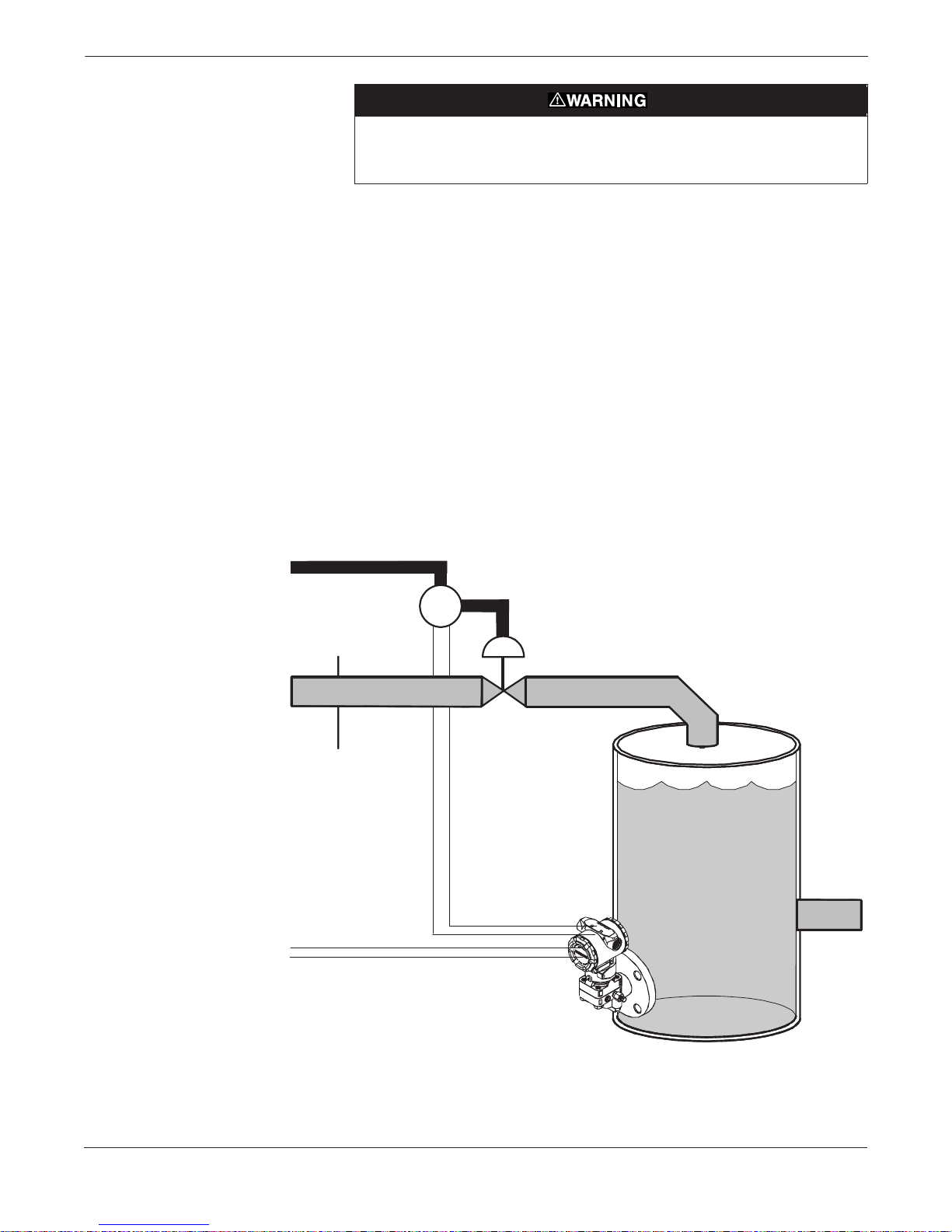
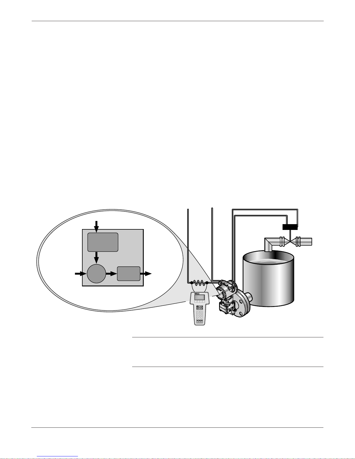
FIGURE 2-1. Typical Level Controller
Installation Site.
The Model 3095 Multivariable Level Controller is a multivariable,
microprocessor-based, analog and digital output device for use in single
loop, level process applications.
The Level Controller directly measures differential pressure (DP) and
computes a separate process variable that represents level in a tank
above a reference point.
The Level Controller uses the level variable in a control function to
compute a control output value. The control function is a PID
algorithm whose output is a 4–20 mA analog signal. A digital
representation of the value of the 4–20 mA output may be obtained
via HART digital communications.
Because the Level Controller is a multivariable device, optional process
variables can be measured and obtained as a secondary HART process
variable. The process variables available via HART are level, DP,
control output (CO), and process temperature (PT).
Air Supply In
Air
Out
I/P Positioner
I/P
Inlet
Valve
Tank
Input
Pipe
Field Wiring
4–20 mA Control Signal
Model 3095
Level Controller
Tank
Outlet
Pipe
3095-3095_01A
2-2
Level Controller Overview and Installation
Figure 2-1 illustrates a single loop level control system. The single
control loop consists of:
• A level process.
• A Level Controller with a 4–20 mA control output signal.
• An electrical-to-pneumatic converting device such as a 3311 I/P.
• An optional positioner device to correct for valve displacement
before valve variations affect the process.
• An actuator device such as a valve.
Figure 2-2 is a more detailed diagram of the level process depicted in
Figure 2-1. The setpoint is the desired process value at which the user
wishes to maintain (control) the process. The error between the setpoint
and the actual process variable (as measured by the sensor) is used by
the controller to determine the value of its output.
The controller output is an electrical current (in mA) which is used by
an electrical-to-pneumatic device, such as an I/P, to control the position
of a valve. A positioner, which is mechanically connected to the moving
part of the valve, automatically adjusts its output pressure in order to
maintain a desired position that bears a predetermined relationship to
the input signal.
FIGURE 2-2. Level Controller
Process Diagram
SETPOINT
Level Target
Tank
Level
4–20 mA
PID
Valve
Position
NOTE
The Level Controller differs from a standard transmitter in
that the 4–20 mA output is a control output, not a differential
pressure (DP) output.
3095\3095_10A
2-3

Rosemount Model 3095 Multivariable™ Level Controller
BEFORE YOU BEGIN
FIGURE 2-3. Level Controller
Installation Flowchart.
Controller Product
START
Unpack the Level
Controller
Review the Level
Manual
Bench
Configure
?
No
B
Review the flowchart shown in Figure 2-3 before you begin installing
the Level Controller. This flowchart summarizes the tasks you should
complete to ensure a successful installation.
B
FIELD
INSTALLATION
(page 2-19
Review Installation
Considerations
Mount
Controller
Make Process
Connections
(Optional) Install
RTD Assembly
Check for Leaks
Complete Wiring
Yes
A
BENCH
CONFIGURE
(page 2-7)
Ensure jumper is
across output
terminals
Connect Bench
Power Supply
A
Connect
Model 275
(Page A-5)
Complete
Configuration
Tasks
(Section 3)
2-4
Remove jumper
from output
terminals
B
Controller
Configured
?
Yes
Perform a
Level Trim
Tune the Loop
DONE
No
Complete
Configuration
Tasks
(Section 3)

Level Controller Overview and Installation
UNPACKING THE LEVEL
CONTROLLER
BECOMING FAMILIAR
WITH THE LEVEL
CONTROLLER
The Level Controller arrives in either one or two shipping containers,
depending on the system ordered.
Level Controller
This box contains the Level Controller. If ordered, this package also
contains an RTD cable and optional mounting hardware. One Model
3095 Multivariable Level Controller Product Manual is included with
each order.
RTD Assembly (Optional)
This box contains the optional Series 68 or Series 78 RTD Assembly
and the Sensor Wiring Instruction Sheet.
When you unpack the Level Controller:
1. Place the shipping containers on a secure bench and open them,
taking care not to damage the contents.
2. Review the packing list to verify that all equipment was received.
3. Inspect the equipment and report any shipping damage to the
carrier.
Figure 2-1 on page 2-2 illustrates a typical Level Controller installation
site; Figure 2-4 shows the exploded view of the Model 3095 Level
Controller. Major components of the Level Controller system and the
Level Controller itself are identified in these figures.
2-5

Rosemount Model 3095 Multivariable™ Level Controller
FIGURE 2-4. Exploded View of the Level
Controller.
Housing
Terminal
Block
O-ring
Cover
Certification
Label
Electronics
Board
Nameplate
Module O-ring
Housing
Locking Screw
RTD Connector
Process Flange O-ring
Flange Adapter O-ring
Optional Flange Adapters
Sensor Module
Drain/Vent Valve
Coplanar Flange
Bolts
2-6
3095-3095A08B.EPS
Level Controller Overview and Installation
BENCH CONFIGURATION
Failure Mode Alarm vs.
Saturation Output Values
Write Protect and
Failure Mode
Alarm Jumpers
Before mounting the Level Controller in the field, the controller can be
configured on the bench using a Model 275 HART Communicator.
NOTE
For bench configuration, a jumper must be installed across the
output terminals.
Failure mode alarm output levels differ from the output values that
occur when applied pressure is outside the range points. When pressure
is outside the range points, the analog output continues to track the
input pressure until reaching the saturation value listed below; the
output does not exceed the listed saturation value regardless of the
applied pressure. For example, for pressures outside the 4–20 range
points, the output saturates at 3.9 mA or 20.8 mA.
When the controller diagnostics detect a failure, the analog output is
set to a specific alarm value that differs from the saturation value to
allow for proper troubleshooting.
Level 4–20 mA Saturation Value 4–20 mA Alarm Value
Low 3.9 mA 3.75 mA
High 20.8 mA 21.75 mA
These jumpers are both located on the electronics board just inside the
electronics housing cover (see Figure 2-5). Set these jumpers during the
commissioning stage on the bench to avoid exposing the controller
electronics to the plant environment after installation.
Once the controller has been configured, the configuration data can be
protected by moving the write protect (security) jumper. When this
jumper is installed, the controller does not allow any changes to its
configuration memory.
In the event of a critical hardware failure in the controller, the
controller automatically drives the analog output either below 3.75 or
above 21.75, depending on the position of the failure alarm jumper.
NOTE
This alarm jumper is different from a level measurement alarm
condition. As part of its normal operation, the Level Controller
continuously monitors its own operation. This automatic diagnostic
routine is a timed series of checks repeated continuously.
If the controller determines that a level measurement alarm exists, the
controller performs one of the two Mode Shed routines (user selected):
– the controller signal freezes at the current level
– the signal switches to a pre-determined mode shed level
See Chapter 4 for additional mode shed information.
When shipped from the factory, the write protect jumper is set to
“OFF,” and the alarm jumper is set to “LO.”
2-7

Rosemount Model 3095 Multivariable™ Level Controller
Use the following steps to change the jumper settings:
1. If the controller is installed, secure the loop and remove power.
2. Remove the housing cover opposite the field terminal side. Do not
remove the instrument cover in explosive atmospheres when the
circuit is alive.
3. Locate the jumper(s) on the output electronics board (see Figure
2-5), then move the jumper(s) to the desired setting.
4. Reattach the housing cover. Metal to metal contact is preferred.
Both controller covers must be fully engaged to meet explosionproof requirements.
5. If the controller is installed, reapply power.
FIGURE 2-5. Write Protect and
Level Controller Alarm Jumpers.
SECURITY
OFF
ON
<
<
>
HI
>
LO
ALARM
NOTE
Security jumper not installed = Not Write Protect ed.
Alarm jumper not installed = High Alarm.
OUTPUT ELECTRONICS BOARD
3095-3095G05A, 3095H05A
2-8
Level Controller Overview and Installation
GENERAL INSTALLATION
CONSIDERATIONS
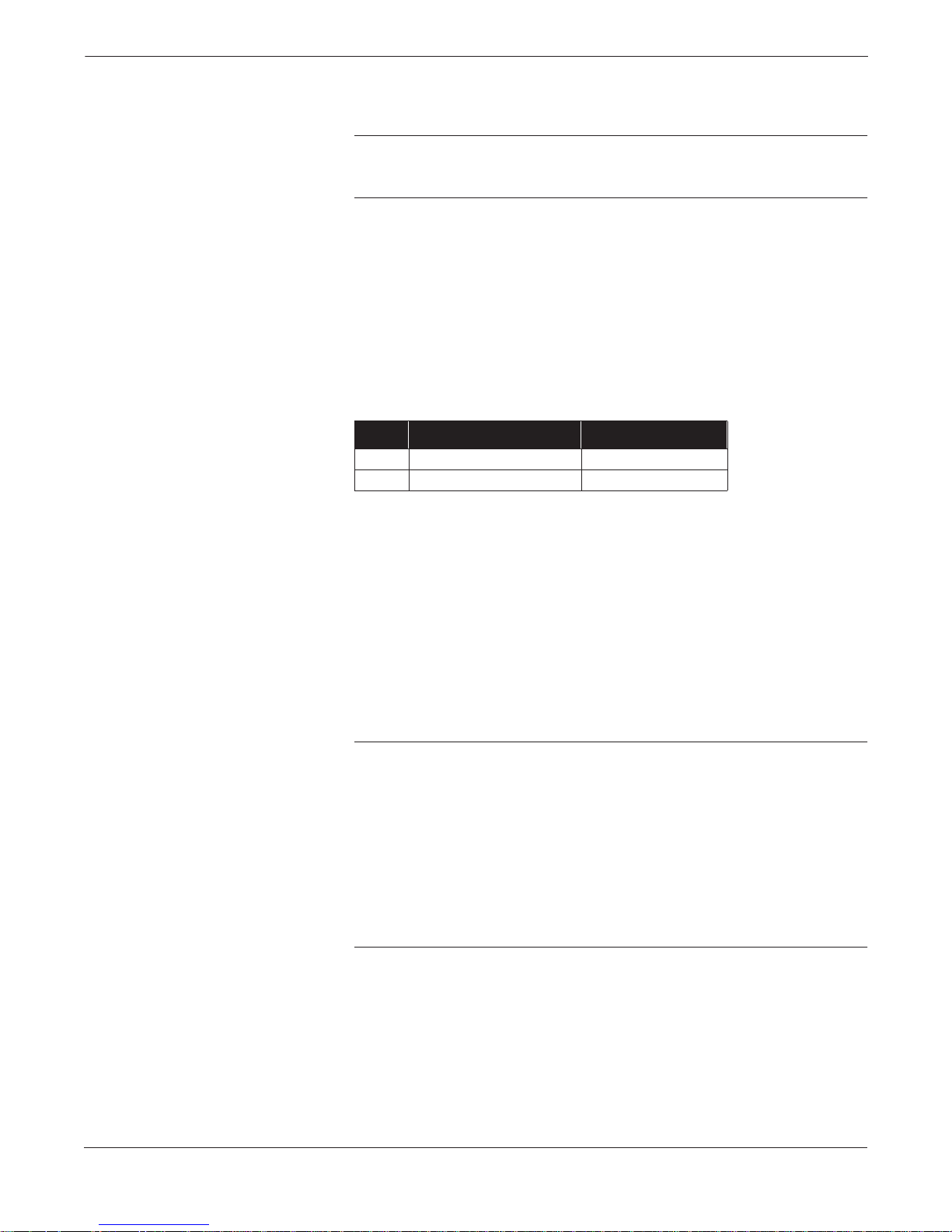
FIGURE 2-6. Dimensional Drawings
of Level Controller.
5.60
(142)
4.93
Meter Cover
(Optional)
0.75 (19)
Clearance for
Cover Removal
(125)
The accuracy of a level control measurement depends upon proper
installation of the controller and impulse piping. The piping between
the process and the controller must accurately transfer the pressure in
order to obtain accurate measurements.
Mount the controller close to the process and use a minimum of impulse
piping to achieve best accuracy. Keep in mind, however, the need for
easy access, safety of personnel, and a suitable controller environment.
(Refer to Figure 2-6 for Level Controller dimensions.) In general, install
the controller so as to minimize vibration, shock, and temperature
fluctuations.
The high pressure side of the level controller must always be plumbed
to the bottom of the tank. For open vessels, the low pressure side of the
Level Controller should be vented. For closed vessels, the low pressure
side must always be plumbed to the top of the tank.
The following sections discuss the factors to consider for a successful
Level Controller installation.
4.20
(107)
Certification
Label
3.12
(79)
4.09
(104)
½–14 NPT Conduit
Connection (2 Places)
0.75 (19)
Clearance for
Cover Removal
Controller
Circuitry
This Side
Nameplate
Drain/Vent
Valve
6.4
(163)
½–14 NPT on Optional Mounting
Adapters. Adapters Can Be
Rotated to Give Connection Centers
of 2.00 (51), 2.125 (54), or 2.25 (57).
NOTE
Dimensions are in inches (m illimeters).
Controller
Connections
This Side
Housing
Rotation
Set Screw
7.07
(180)
8.17
(208)
¼–18 NPT on Coplanar Flange
for Pressure Connection
without the Use of
Mounting Adapters
3095-G05A, H05A
2-9

Rosemount Model 3095 Multivariable™ Level Controller
MECHANICAL
CONSIDERATIONS
Mounting Considerations
TABLE 2-1. Controller Weight.
Bolt Installation Guidelines
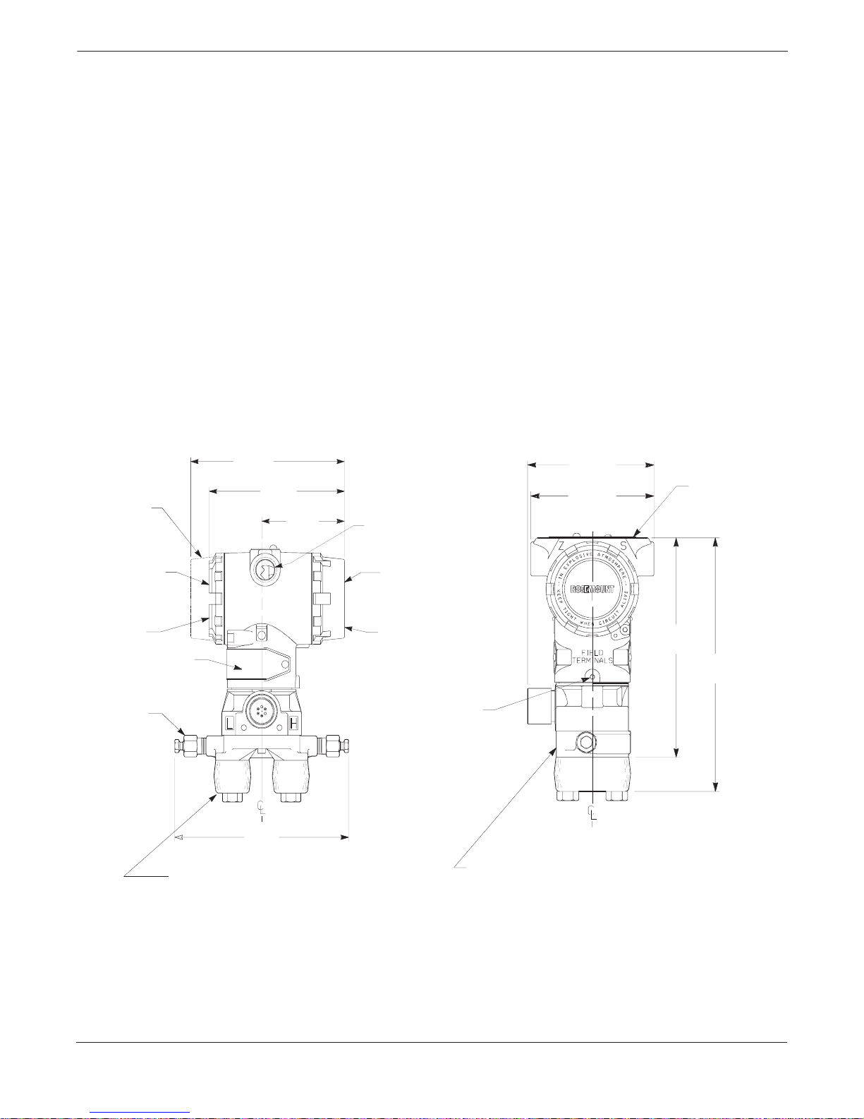
The Level Controller may be direct-mounted, mounted with one or two
remote diaphragm seals, mounted with a level flange, or attached to a
two-inch pipe with an optional mounting bracket. Figure 2-7 illustrates
Level Controller mounting configurations; Figure 2-6 shows the Level
Controller dimensions.
The Level Controller total weight varies depending on the components
ordered (see Table 2-1). This weight must be securely supported.
Component Weight lb (kg)
Level Controller
SST Mounting Bracke t
12 ft (3.66 m) RTD Shielded Cable
12 ft (3.66 m) RTD Armored Cab le
24 ft (7.32 m) RTD Shielded Cable
24 ft (7.32 m) RTD Armored Cab le
6.0 (2.7)
1.0 (0.4)
0.5 (0.2)
1.1 (0.5)
1.0 (0.4)
2.2 (1.0)
The following guidelines have been established to ensure a tight
flange, adapter, or manifold seal. Use only bolts supplied with the
controller or sold by Rosemount Inc. as a spare part to the Level
Controller. Unauthorized parts can affect product performance and
may impair the protection provided by the equipment.
™
The Level Controller is shipped with the Coplanar
flange installed
with four 1.75-inch flange bolts. The following bolts also are supplied
to facilitate other mounting configurations:
• Four 2.25-inch manifold/flange bolts for mounting the Coplanar
flange on a three-valve manifold. In this configuration, the
1.75-inch bolts may be used to mount the flange adapters to the
process connection side of the manifold.
• (Optional) If flange adapters are ordered, four 2.88-inch
flange/adapter bolts for mounting the flange adapters to the
Coplanar flange.
Figure 2-7 shows the optional mounting bracket and mounting
configurations. Figure 2-8 shows mounting bolts and bolting
configuration for the Level Controller with the Coplanar flange.
Stainless steel bolts supplied by Rosemount Inc. are coated with a
lubricant to ease installation. Carbon steel bolts do not require
lubrication. Do not apply additional lubricant when installing
either type of bolt. Use the equipment only as specified in this manual.
Failure to do so may impair the protection provided by the
equipment. Bolts supplied by Rosemount Inc. are identified by the
following head markings:
Carbon Steel Head Markings (CS)
B7M
Stainless Steel Head Markings (SST)
2-10
316
316
R
B8M
STM
316 316
SW
316
3051-3031I06A
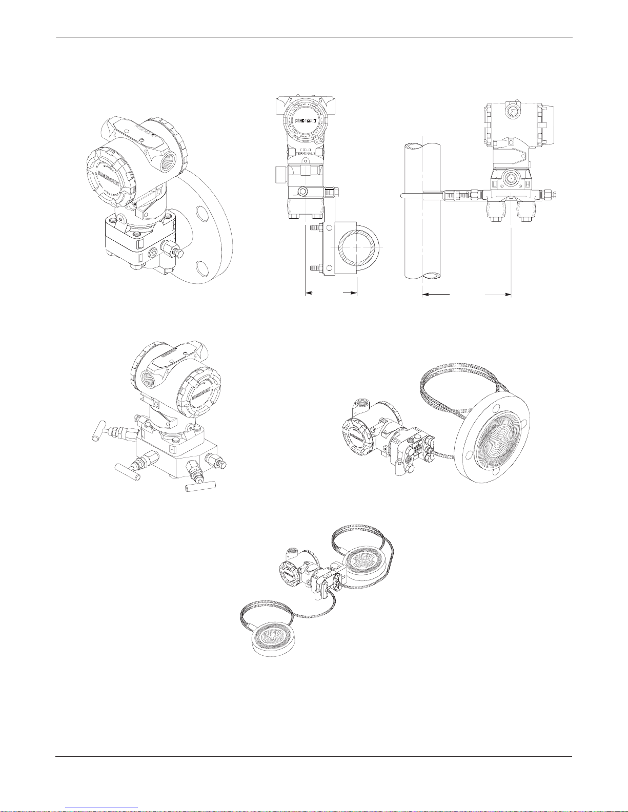
FIGURE 2-7. Mounting Configu rati ons and Opt ion al Mo unti ng Acces so ries .
Level Controller Overview and Installation
LEVEL FLANGE
INTEGRAL MOUNT MANIFOLD
3.54
(90)
6.25
(159)
PIPE MOUNTED WITH
OPTIONAL BRACKET
ONE DIAPHRAGM SEAL
NOTE
Dimensions are in inches (millimeters).
TWO DIAPHRAGM SEALS
3001-3051AO1A, 3095-3095K04A, 3095L04A 3051\305-3031A29B, 3051-3051A29B, A28A
2-11

Rosemount Model 3095 Multivariable™ Level Controller
FIGURE 2-8. Coplanar Mounting Bolts and Boltin g Co nfig ura tion s for Coplanar Flange.
1.75 (44) x 4
CONTROLLER WITH
FLANGE BOLTS
Description Qty.
Flange bolts
Flange/adapter bolts
Manifold/flange bolts
4
4
4
Size in.
(mm)
1.75 (44)
2.88 (73)
2.25 (57)
2.88 (73) x 4
CONTROLLER WITH
OPTIONAL FLANGE ADAPTERS
AND FLANGE/ADAPTER BOLTS
NOTE
Dimensions are in inches (millimeters).
2.25 (57) x 4
1.75 (44) x 4
CONTROLLER W ITH 3 -VALVE MANIFOLD
MANIFOLD/FLANG E BOLTS
FLANGE ADAPTERS
AND FLANGE/ADAPTER BOLTS
3095-3095D05M, 3095C05A, 3095C29A
2-12

Level Controller Overview and Installation
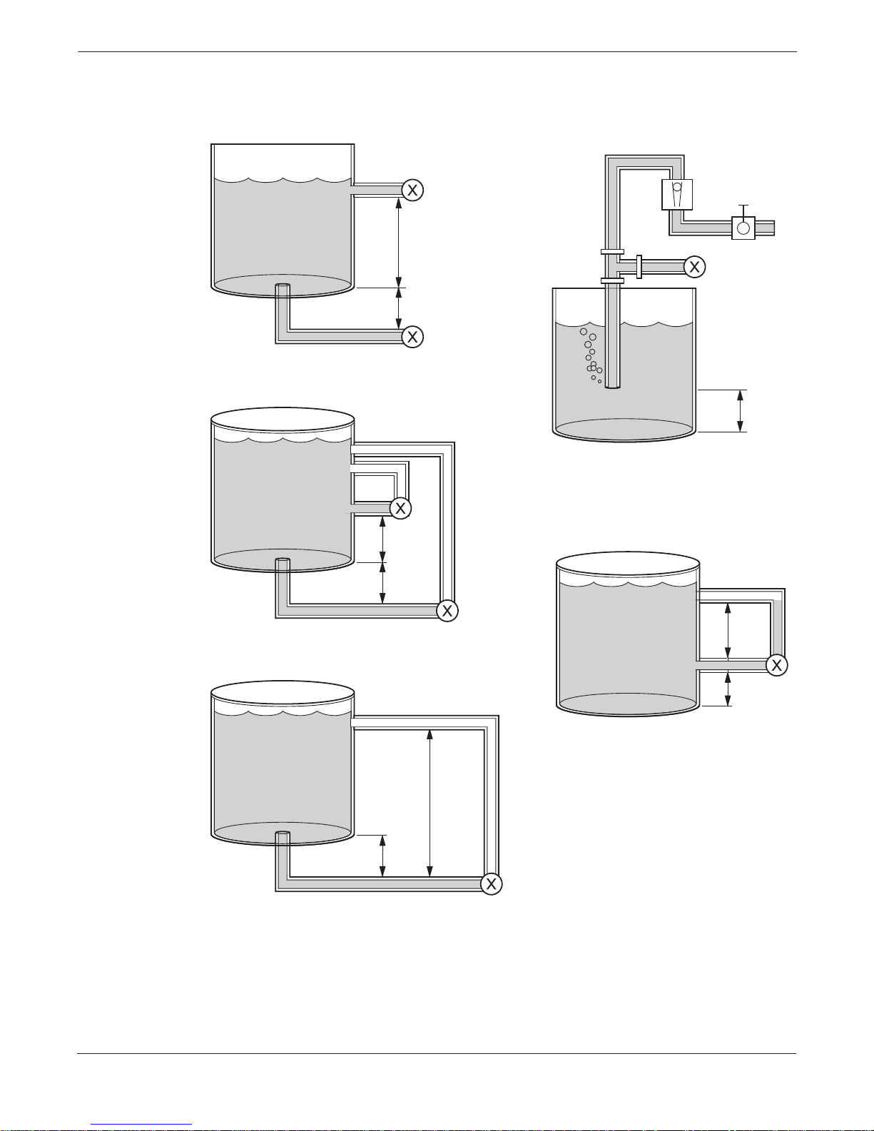
EXAMPLE
INSTALLATIONS
Open Tanks
Open Tanks with Bubbler
Closed Tanks with Dry Leg
Figure 2-9 illustrates example installations for the Model 3095 Level
Controller. “H” and “L” in the examples correspond to the H and L
stamped on the Level Controller sensor module and indicate which way
the controller is to be installed.
In open vessels a pressure controller mounted near the bottom of the
tank will measure the pressure corresponding to the height of the fluid
above it.
The connection is made to the high pressure side of the controller. The
low pressure side is vented to atmosphere.
Process Connections Options: Impulse piping; one diaphragm seal,
(capillary or direct mount) level flange.
A “bubbler” system using a top-mounted controller can be used in open
vessels. This system consists of an air supply, a constant flow regulator,
a controller, and tube extending down into the vessel.
Air is bubbled through the tube at a constant flow rate. The pressure
required to maintain flow is determined by the vertical height of the
liquid above the tube opening, process density, and local gravity.
Process Connections Option: Impulse piping,
In closed vessels, the pressure above the liquid will affect the pressure
measured at the bottom. The pressure at the bottom of the vessel is
determined by the height of the liquid, the density of the liquid, plus
the vessel pressure.
Closed Tanks with Wet Leg
To measure true level, the vessel pressure must be subtracted from the
measurement. This is accomplished by making a pressure tap at the top
of the vessel and connecting this to the low side of a differential pressure
controller. Vessel pressure is now equally applied to both the high and
low sides of the controller. The resulting differential pressure is
determined by liquid height, process density, and specific gravity.
If the gas above the liquid does not condense, the piping for the low side
of the controller will remain empty. Calculations for determining the
controller height will be the same as those shown for open vessel
bottom mounted controllers.
Process Connections Options: Impulse piping; one diaphragm seal
(capillary or direct mount); two diaphragm seals, level flange.
If the gas above the liquid condenses, the piping for the low side of the
controller will slowly fill up with liquid. To eliminate this potential
error, the pipe is purposely filled with a convenient reference fluid.
The reference fluid exerts a head pressure on the low side of the
controller.
Process Connections Options: Impulse piping; one diaphragm seal
(capillary or direct mount); two diaphragm seals, level flange.
2-13
Rosemount Model 3095 Multivariable™ Level Controller
FIGURE 2-9. Example Install ati ons .
H
L
Controller Height = C
Controller Height = A
or
Controller Height = -B
Controller Height = A
or
Controller Height = -B
OPEN TANK
CLOSED TANK
WITH DRY LEG
A
H
L
B
L
H
C
OPEN TANK
WITH BUBBLER
H
L
A
B
L
H
Controller Height = E + D
E
L
2-14
M
N
CLOSED TANK WITH WET LEG,
CONTROLLER B E LOW BOTTOM OF TANK
D
CLOSED TANK WITH WET LEG,
CLOSED TANK WITH WET LEG,
CONTROLLER ABO VE BO T TOM OF TANK
CONTROLLER ABO VE BO T TOM OF TANK
Controller Height = M - N
H
L
H
3095-3095_01A

Level Controller Overview and Installation
TAP CONSIDERATIONS
Impulse Piping
When the Level Controller is oriented on its side, the Coplanar™ flange
may be mounted to ensure proper venting or draining. Mount the flange
so that the drain/vent connections are on the top half of the flange for
liquid service.
CAUTION
In elevated temperature services, it is important that temperatures at
the Coplanar process flanges not exceed 250 °F (121 °C).
The piping between the process and the controller must accurately
transfer the pressure in order to obtain accurate control. In this
pressure transfer, there are five possible sources of error: leaks, friction
loss (particularly if purging is used), trapped gas in a liquid line, and
temperature-induced or other density variation between the legs.
The best location for the Level Controller in relation to the process pipe
depends on the process itself. Consider the following guidelines in
determining controller location and placement of impulse piping:
• Keep impulse piping as short as possible.
• Slope the impulse piping at least one inch per foot (8 centimeters
per meter) upward from the controller toward the process
connection for liquid.
• Avoid high points in liquid lines.
• Make sure both impulse legs are the same temperature.
• Use impulse piping large enough to avoid friction effects and
prevent blockage.
• Vent all gas from liquid piping legs.
• Avoid purging through the controller.
• Keep corrosive or hot (above 250 °F (121 °C)) process material out
of direct contact with the sensor module and flanges.
• Prevent sediment deposits in the impulse piping.
• Avoid conditions that might allow process fluid to freeze within
the process flange.
Diaphragm Seals
Because instrument response time is directly proportional to capillary
length, and the fill fluid volume in the capillary changes with
temperature to affect the output, care must be taken to optimize
performance:
• Keep the capillary length as short as possible.
• Mount a controller with one seal at the same level, or below the
seal and process connection. Use direct mount when possible.
• In vacuum applications, mount the controller below the lower tap
to ensure proper operation. This requirement applies to both oneand two-seal systems.
• Avoid mounting seals and capillaries in direct sunlight.
• Keep the capillary lengths equal when two seals are involved.
• Rezero the controller on a seasonal basis.
• Never attempt to disconnect the seals or capillaries. Doing so will
void the warranty.
2-15

Rosemount Model 3095 Multivariable™ Level Controller
ENVIRONMENTAL
CONSIDERATIONS
Access Requirements
Process Flange Orientation The process flanges must be oriented so that process connections can be
Housing Rotation The electronics housing may be rotated to improve field access to the
Mount the Level Controller to minimize ambient temperature changes.
Section 6: Level Controller Specifications and Reference Data
lists the Model 3095 temperature operating limits. Mount the Level
Controller to avoid vibration and mechanical shock, and to avoid
external contact with corrosive materials.
When choosing an installation location and position, take into account
the need for access to the controller.
made. In addition, consider the possible need for testing the controller.
CAUTION
Drain/vent valves must be oriented so that process fluid is directed
away from technicians when the valves are used.
two compartments. To rotate the housing less than 90 degrees, release
the housing rotation set screw and turn the housing not more than 90
degrees from the orientation shown in Figure 2-7 on page 2-11. To
rotate the housing more than 90 degrees, follow steps 1–6 of the
disassembly procedure on page 5-11.
CAUTION
Rotating the housing more than 90 degrees without performing the
disassembly procedure may damage the Level Controller sensor module.
Terminal Side of
Electronics Housing
Circuit Side of
Electronics Housing
Wiring connections are made through the conduit openings on the top
side of the Level Controller housing. The field terminal side is marked
on the housing.
Mount the Level Controller so that the terminal side is accessible.
A 0.75-inch clearance is required for cover removal.
Install a conduit plug on the unused side of the conduit opening.
The circuit compartment should not routinely need to be opened when
the unit is in service; however, provide 0.75 inches minimum clearance
if possible to allow access.
2-16
Level Controller Overview and Installation
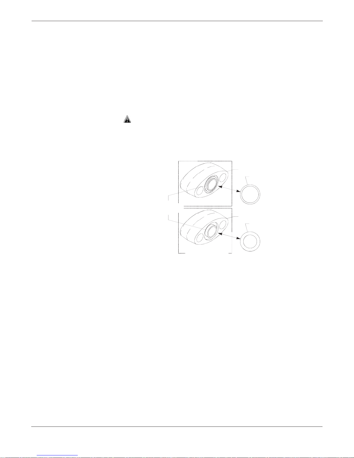
Unique O-ring
Grooves
MODEL 3051/2024/3001/3095/Level Contro lle r
MODEL 1151
Flange Adapter
O-ring
Flange Adapt er
O-ring
3051-0569A01A
Process Considerations
FIGURE 2-10. Flange Adapter O-rings.
Level Controller process connections on the controller flange are ¼–18
NPT. Flange adapter unions with ½–14 NPT connections are available as
options. These are Class 2 threads; use your plant-approved lubricant or
sealant when making the process connections. The process connections
1
on the controller flange are on 2
/8-inch (54-mm) centers to allow direct
mounting to a three- or five-valve manifold. By rotating one or both of
1
the flange adapters, connection centers of 2, 2
/8, or 2¼ inches (51, 54,
or 57 mm) may be obtained.
There are two styles of Rosemount flange adapters, each requiring a
unique O-ring, as shown below. Each flange adapter is distinguished
by its unique groove. Use only the O-ring designed to seal with the
corresponding flange adapter.
Use only the O-ring designed to seal with the corresponding flange
adapter. Failure to install proper flange adapter O-rings can cause
process leaks.
When compressed, Teflon® O-rings tend to cold flow, which aids in their
sealing capabilities. Whenever flanges or adapters are removed, visually
inspect the Teflon O-rings. Replace them if there are any signs of
damage, such as nicks or cuts. If they are undamaged, they can be
reused. If the O-rings are replaced, the flange bolts may need to be
retorqued after installation to compensate for cold flow. Refer to the
process sensor body reassembly procedure on page 5-16.
2-17
Rosemount Model 3095 Multivariable™ Level Controller
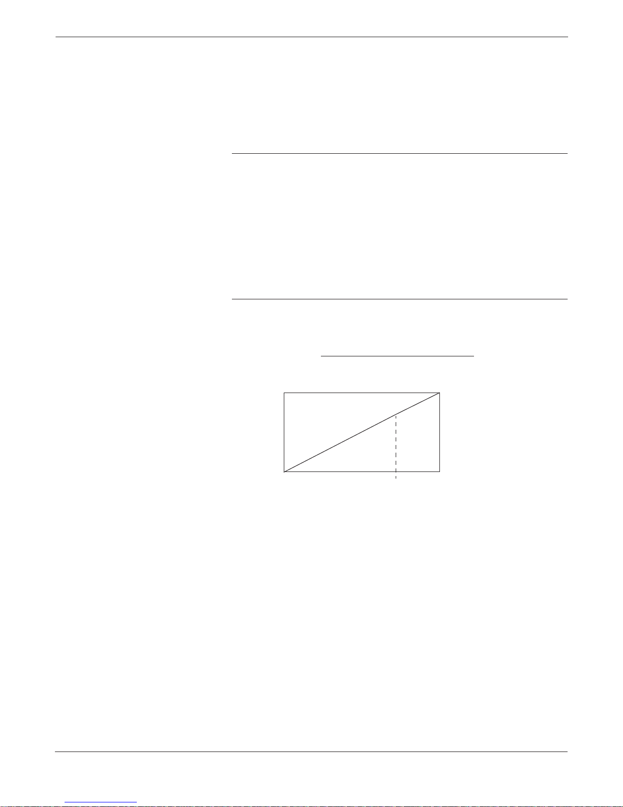
ELECTRICAL
CONSIDERATIONS
FIGURE 2-11. Power Supply
Load Limitations.
The signal terminals are located in a compartment of the electronics
housing separate from the controller electronics. Figure 2-11 illustrates
power supply load limitations for the controller.
The dc power supply should provide power with less than 2% ripple.
The total resistance load is the sum of the resistance of the signal leads
and the load resistor, actuator, indicator, and related pieces. Note that
the resistance of intrinsic safety barriers, if used, must be included.
NOTE
A loop resistance between 250–1100 ohms inclusive is required to
communicate with a HART Communicator. With 250 ohms of loop
resistance, a power supply voltage of at least 16.5 V dc is required.
Quick troubleshooting check: there must be at least 11.0 V dc across the
controller terminals.
If a single power supply is used to power more than one Level
Controller, the power supply used, and circuitry common to the
controllers, should not have more than 20 ohms of impedance at 1200 Hz.
For CSA approval, power supply must not exceed 42.4 V dc.
Loop resistance is determined by the voltage level of the external power supply, as described by:
Max. Loop Resistance = Power Supply Voltage–11.0–Actuator Voltage
0.022
(1)
2000
Load (Ohms)
0
11.0 16.5
HART protocol communicat ion requi res a loop resista nc e valu e
between 250–1100 ohms, inclusive.
(1) Actuator Voltage is the maximum voltage drop across the actuator device.
(1) For CSA approval, power supply must not exceed 42.4 V dc.
4–20 mA dc
Operating Region
35.2
42.4
Power Supply Voltage
55
(2)
3051-0103A
2-18
Level Controller Overview and Installation
FIELD INSTALLATION
PROCEDURE
Field Installation
Equipment
Review Installation
Considerations
Mount Controller and
Install Bolts
The field installation procedure involves mounting the Level
Controller, connecting it to the process, and completing the field wiring.
The following equipment and tools are not provided with the Level
Controller. Be sure to review this list before field installing the controller.
• Installation tools
• Field wire between the power supply and the Level Controller
and between the Level Controller and the actuator device
• Actuator device
• Barriers or seals required for hazardous locations
• Conduit
• 2-in. mounting pipe or saddles
• Power supply
• 3- or 5-valve manifold
• Impulse piping
• Tie wraps
• Load resistor
Review the installation considerations described on pages 2-9 through
2-18 in this section to determine the location for the Level Controller.
Mount the Level Controller in the desired location, and install flange or
flange/adapter bolts. Only use bolts supplied with the Level Controller
or sold by Rosemount Inc. as a spare part to the Level Controller.
Unauthorized parts can affect product performance and may impair the
protection provided by the equipment.
TABLE 2-2. Bolt Installation
Torque Values.
Make Process
Connections
1. Finger-tighten the bolts.
2. Torque the bolts to the initial torque value (see Table 2-2) using a
cross-pattern.
3. Torque the bolts to the final torque value (see Table 2-2) using the
same cross-pattern.
Bolt Material Initial Torque Value Final Torque Value
Carbon Steel (CS) 300 in-lb (407 n-m) 650 in-lb (881 n-m)
Stainless Steel (SST) 150 in-lb (203 n-m) 300 in-lb (407 n-m )
When installing the controller to one of the mounting brackets, torque
the mounting bracket bolts to 125 in-lb (169 n-m).
Connect the Level Controller to the process. All four flange bolts must
be installed and tight before applying pressure, or process leakage will
result. When properly installed, the flange bolts protrude through the
top of the module housing. Attempting to remove the flange bolts while
the controller is in service will result in process leaks.
2-19
Rosemount Model 3095 Multivariable™ Level Controller
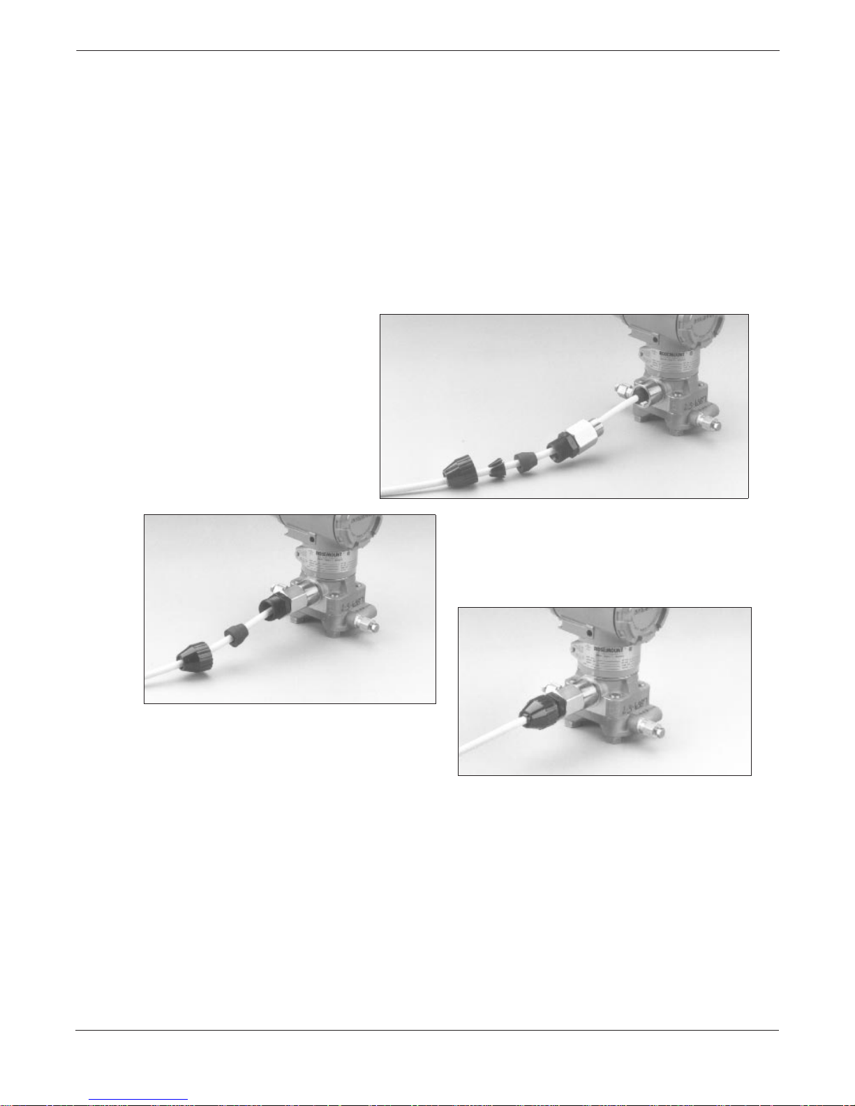
Install RTD Assembly
FIRST, FULLY ENGAGE
THE BLACK CABLE
CONNECTOR
The external RTD assembly is optional and not required for Level
Controller operation. The RTD Assembly allows you to read
temperatures as a HART variable only.
To install the Series 68 or Series 78 RTD Assembly:
1. Mount the RTD Assembly in the desired location. Refer to the
appropriate differential producer standard concerning
recommended RTD installation location.
2. Connect the RTD cable to the Level Controller RTD connector.
First, fully engage the black cable connector, then screw in
and tighten the cable adapter until metal to metal contact occurs
(see photos).
SECOND, SCREW IN AND
TIGHTEN THE CABLE ADAPTER
UNTIL METAL TO METAL
CONTACT OCCURS
2-20
3095-069AB, 068AB, 067AB
THIRD, SCREW IN AND TIGHTEN
THE STRAIN RELIEF CLAMP
3. (Optional) If using an armored, shielded cable, install the
armored cable compression seal as illustrated below, and use a
pliers to tighten the cap onto the compression fitting
4. Make all necessary wiring connections inside the RTD Flat
Connection Head as explained in the Sensor Wiring Instructions
included with the RTD.
 Loading...