

Page 1

Reference Manual
00809-0100-4801, Rev HA
October 2018
Rosemount™ 3051S Series Scalable™ Pressure,
Flow, and Level Solution
with HART® Protocol
Page 2

Page 3

Reference Manual
00809-0100-4801, Rev HA
Contents
1Section 1: Introduction
2Section 2: Configuration
Contents
October 2018
1.1 Using this manual . . . . . . . . . . . . . . . . . . . . . . . . . . . . . . . . . . . . . . . . . . . . . . . . . . . . . . . . . . . . . . . . . 1
1.2 Models covered . . . . . . . . . . . . . . . . . . . . . . . . . . . . . . . . . . . . . . . . . . . . . . . . . . . . . . . . . . . . . . . . . . . 2
1.3 Product recycling/disposal. . . . . . . . . . . . . . . . . . . . . . . . . . . . . . . . . . . . . . . . . . . . . . . . . . . . . . . . . . 3
2.1 Overview . . . . . . . . . . . . . . . . . . . . . . . . . . . . . . . . . . . . . . . . . . . . . . . . . . . . . . . . . . . . . . . . . . . . . . . . . 5
2.1.1 Example software function . . . . . . . . . . . . . . . . . . . . . . . . . . . . . . . . . . . . . . . . . . . . . . . . . . . . 5
2.2 Safety messages. . . . . . . . . . . . . . . . . . . . . . . . . . . . . . . . . . . . . . . . . . . . . . . . . . . . . . . . . . . . . . . . . . . 6
2.3 Commissioning on the bench . . . . . . . . . . . . . . . . . . . . . . . . . . . . . . . . . . . . . . . . . . . . . . . . . . . . . . . 6
2.3.1 Setting the loop to manual. . . . . . . . . . . . . . . . . . . . . . . . . . . . . . . . . . . . . . . . . . . . . . . . . . . . 6
2.3.2 Wiring diagrams . . . . . . . . . . . . . . . . . . . . . . . . . . . . . . . . . . . . . . . . . . . . . . . . . . . . . . . . . . . . . 7
2.4 Field Communicator . . . . . . . . . . . . . . . . . . . . . . . . . . . . . . . . . . . . . . . . . . . . . . . . . . . . . . . . . . . . . . . 8
2.4.1 Field Communicator user interface. . . . . . . . . . . . . . . . . . . . . . . . . . . . . . . . . . . . . . . . . . . . . 8
2.5 Field Communicator menu trees . . . . . . . . . . . . . . . . . . . . . . . . . . . . . . . . . . . . . . . . . . . . . . . . . . . . 9
2.5.1 Device Dashboard menu tree. . . . . . . . . . . . . . . . . . . . . . . . . . . . . . . . . . . . . . . . . . . . . . . . . . 9
2.5.2 HART 5 with Diagnostic menu trees . . . . . . . . . . . . . . . . . . . . . . . . . . . . . . . . . . . . . . . . . . . 12
2.5.3 HART 7 menu trees . . . . . . . . . . . . . . . . . . . . . . . . . . . . . . . . . . . . . . . . . . . . . . . . . . . . . . . . . 16
2.5.4 Device Dashboard Fast Key sequence . . . . . . . . . . . . . . . . . . . . . . . . . . . . . . . . . . . . . . . . . 20
2.5.5 HART 5 with Diagnostics Fast Key sequence . . . . . . . . . . . . . . . . . . . . . . . . . . . . . . . . . . . . 21
2.5.6 HART 7 Fast Key sequence . . . . . . . . . . . . . . . . . . . . . . . . . . . . . . . . . . . . . . . . . . . . . . . . . . . 22
2.6 Check output . . . . . . . . . . . . . . . . . . . . . . . . . . . . . . . . . . . . . . . . . . . . . . . . . . . . . . . . . . . . . . . . . . . . 22
2.6.1 Process variables. . . . . . . . . . . . . . . . . . . . . . . . . . . . . . . . . . . . . . . . . . . . . . . . . . . . . . . . . . . . 23
2.6.2 Module temperature . . . . . . . . . . . . . . . . . . . . . . . . . . . . . . . . . . . . . . . . . . . . . . . . . . . . . . . . 23
2.7 Basic setup . . . . . . . . . . . . . . . . . . . . . . . . . . . . . . . . . . . . . . . . . . . . . . . . . . . . . . . . . . . . . . . . . . . . . . 24
2.7.1 Set process variable units . . . . . . . . . . . . . . . . . . . . . . . . . . . . . . . . . . . . . . . . . . . . . . . . . . . . 24
2.7.2 Set output (transfer function) . . . . . . . . . . . . . . . . . . . . . . . . . . . . . . . . . . . . . . . . . . . . . . . . 24
2.7.3 Rerange . . . . . . . . . . . . . . . . . . . . . . . . . . . . . . . . . . . . . . . . . . . . . . . . . . . . . . . . . . . . . . . . . . . 26
2.7.4 Damping . . . . . . . . . . . . . . . . . . . . . . . . . . . . . . . . . . . . . . . . . . . . . . . . . . . . . . . . . . . . . . . . . . 28
2.8 LCD display (Optional Order Code) . . . . . . . . . . . . . . . . . . . . . . . . . . . . . . . . . . . . . . . . . . . . . . . . . 29
2.9 Detailed setup . . . . . . . . . . . . . . . . . . . . . . . . . . . . . . . . . . . . . . . . . . . . . . . . . . . . . . . . . . . . . . . . . . . 29
2.9.1 Failure mode alarm and saturation . . . . . . . . . . . . . . . . . . . . . . . . . . . . . . . . . . . . . . . . . . . . 29
2.9.2 Alarm and saturation level configuration. . . . . . . . . . . . . . . . . . . . . . . . . . . . . . . . . . . . . . . 31
Content s
2.9.3 Alarm and saturation levels for burst mode . . . . . . . . . . . . . . . . . . . . . . . . . . . . . . . . . . . . 31
2.9.4 Alarm and saturation values for multidrop mode . . . . . . . . . . . . . . . . . . . . . . . . . . . . . . . 31
i
Page 4

Contents
October 2018
Reference Manual
00809-0100-4801, Rev HA
2.9.5 Alarm level verification . . . . . . . . . . . . . . . . . . . . . . . . . . . . . . . . . . . . . . . . . . . . . . . . . . . . . . 32
2.9.6 Process Alerts . . . . . . . . . . . . . . . . . . . . . . . . . . . . . . . . . . . . . . . . . . . . . . . . . . . . . . . . . . . . . . 32
2.9.7 Scaled variable configuration. . . . . . . . . . . . . . . . . . . . . . . . . . . . . . . . . . . . . . . . . . . . . . . . . 33
2.9.8 Re-mapping . . . . . . . . . . . . . . . . . . . . . . . . . . . . . . . . . . . . . . . . . . . . . . . . . . . . . . . . . . . . . . . . 36
2.9.9 Module temperature unit . . . . . . . . . . . . . . . . . . . . . . . . . . . . . . . . . . . . . . . . . . . . . . . . . . . . 37
2.10 Diagnostics and service . . . . . . . . . . . . . . . . . . . . . . . . . . . . . . . . . . . . . . . . . . . . . . . . . . . . . . . . . . 38
2.10.1 Loop test . . . . . . . . . . . . . . . . . . . . . . . . . . . . . . . . . . . . . . . . . . . . . . . . . . . . . . . . . . . . . . . . . 38
2.10.2 Simulate device variables . . . . . . . . . . . . . . . . . . . . . . . . . . . . . . . . . . . . . . . . . . . . . . . . . . . 39
2.11 Advanced functions . . . . . . . . . . . . . . . . . . . . . . . . . . . . . . . . . . . . . . . . . . . . . . . . . . . . . . . . . . . . . 39
2.11.1 Saving, recalling, and cloning configuration data . . . . . . . . . . . . . . . . . . . . . . . . . . . . . . 39
2.11.2 Burst mode . . . . . . . . . . . . . . . . . . . . . . . . . . . . . . . . . . . . . . . . . . . . . . . . . . . . . . . . . . . . . . . 41
2.12 Multidrop communication . . . . . . . . . . . . . . . . . . . . . . . . . . . . . . . . . . . . . . . . . . . . . . . . . . . . . . . 42
2.12.1 Changing a transmitter address . . . . . . . . . . . . . . . . . . . . . . . . . . . . . . . . . . . . . . . . . . . . . 43
2.12.2 Communicating with a multidropped transmitter . . . . . . . . . . . . . . . . . . . . . . . . . . . . . 43
3Section 3: Hardware Installation
3.1 Overview . . . . . . . . . . . . . . . . . . . . . . . . . . . . . . . . . . . . . . . . . . . . . . . . . . . . . . . . . . . . . . . . . . . . . . . . 45
3.2 Safety messages. . . . . . . . . . . . . . . . . . . . . . . . . . . . . . . . . . . . . . . . . . . . . . . . . . . . . . . . . . . . . . . . . . 45
3.3 Considerations . . . . . . . . . . . . . . . . . . . . . . . . . . . . . . . . . . . . . . . . . . . . . . . . . . . . . . . . . . . . . . . . . . . 46
3.3.1 Installation considerations . . . . . . . . . . . . . . . . . . . . . . . . . . . . . . . . . . . . . . . . . . . . . . . . . . . 46
3.3.2 Environmental considerations . . . . . . . . . . . . . . . . . . . . . . . . . . . . . . . . . . . . . . . . . . . . . . . . 47
3.3.3 Mechanical considerations . . . . . . . . . . . . . . . . . . . . . . . . . . . . . . . . . . . . . . . . . . . . . . . . . . . 47
3.3.4 Draft range considerations . . . . . . . . . . . . . . . . . . . . . . . . . . . . . . . . . . . . . . . . . . . . . . . . . . . 48
3.4 Installation procedures. . . . . . . . . . . . . . . . . . . . . . . . . . . . . . . . . . . . . . . . . . . . . . . . . . . . . . . . . . . . 49
3.4.1 Mount the transmitter. . . . . . . . . . . . . . . . . . . . . . . . . . . . . . . . . . . . . . . . . . . . . . . . . . . . . . . 50
3.4.2 Configure alarm and security switch. . . . . . . . . . . . . . . . . . . . . . . . . . . . . . . . . . . . . . . . . . . 55
3.4.3 Impulse piping . . . . . . . . . . . . . . . . . . . . . . . . . . . . . . . . . . . . . . . . . . . . . . . . . . . . . . . . . . . . . 56
3.4.4 Process connections . . . . . . . . . . . . . . . . . . . . . . . . . . . . . . . . . . . . . . . . . . . . . . . . . . . . . . . . 57
3.4.5 In-line process connection . . . . . . . . . . . . . . . . . . . . . . . . . . . . . . . . . . . . . . . . . . . . . . . . . . . 57
3.5 Rosemount 305, 306, and 304 Manifolds . . . . . . . . . . . . . . . . . . . . . . . . . . . . . . . . . . . . . . . . . . . . 58
3.5.1 Rosemount 305 Integral Manifold installation procedure . . . . . . . . . . . . . . . . . . . . . . . . 59
3.5.2 Rosemount 306 Integral Manifold installation procedure . . . . . . . . . . . . . . . . . . . . . . . . 60
3.5.3 Rosemount 304 Conventional Manifold installation procedure . . . . . . . . . . . . . . . . . . . 60
3.5.4 Manifold operation. . . . . . . . . . . . . . . . . . . . . . . . . . . . . . . . . . . . . . . . . . . . . . . . . . . . . . . . . . 60
3.6 Wiring the device. . . . . . . . . . . . . . . . . . . . . . . . . . . . . . . . . . . . . . . . . . . . . . . . . . . . . . . . . . . . . . . . . 64
3.6.1 Remove orange conduit plugs . . . . . . . . . . . . . . . . . . . . . . . . . . . . . . . . . . . . . . . . . . . . . . . . 64
3.6.2 Wire the device . . . . . . . . . . . . . . . . . . . . . . . . . . . . . . . . . . . . . . . . . . . . . . . . . . . . . . . . . . . . . 65
3.6.3 Ground the transmitter housing . . . . . . . . . . . . . . . . . . . . . . . . . . . . . . . . . . . . . . . . . . . . . . 67
ii
Contents
Page 5

Reference Manual
00809-0100-4801, Rev HA
4Section 4: Operation and Maintenance
Contents
October 2018
3.6.4 Remote display wiring and power up . . . . . . . . . . . . . . . . . . . . . . . . . . . . . . . . . . . . . . . . . . 68
3.6.5 eurofast/minifast connection. . . . . . . . . . . . . . . . . . . . . . . . . . . . . . . . . . . . . . . . . . . . . . . . . 69
3.6.6 Quick Connect wiring . . . . . . . . . . . . . . . . . . . . . . . . . . . . . . . . . . . . . . . . . . . . . . . . . . . . . . . 70
3.6.7 Power the transmitter . . . . . . . . . . . . . . . . . . . . . . . . . . . . . . . . . . . . . . . . . . . . . . . . . . . . . . . 71
3.6.8 Cover jam screw . . . . . . . . . . . . . . . . . . . . . . . . . . . . . . . . . . . . . . . . . . . . . . . . . . . . . . . . . . . . 71
4.1 Overview . . . . . . . . . . . . . . . . . . . . . . . . . . . . . . . . . . . . . . . . . . . . . . . . . . . . . . . . . . . . . . . . . . . . . . . . 73
4.2 Calibration for HART Protocol . . . . . . . . . . . . . . . . . . . . . . . . . . . . . . . . . . . . . . . . . . . . . . . . . . . . . . 73
4.2.1 Calibration overview . . . . . . . . . . . . . . . . . . . . . . . . . . . . . . . . . . . . . . . . . . . . . . . . . . . . . . . . 74
4.2.2 Determining calibration frequency . . . . . . . . . . . . . . . . . . . . . . . . . . . . . . . . . . . . . . . . . . . . 75
4.2.3 Selecting a trim procedure . . . . . . . . . . . . . . . . . . . . . . . . . . . . . . . . . . . . . . . . . . . . . . . . . . . 76
4.2.4 Sensor trim overview . . . . . . . . . . . . . . . . . . . . . . . . . . . . . . . . . . . . . . . . . . . . . . . . . . . . . . . . 76
4.2.5 Zero trim . . . . . . . . . . . . . . . . . . . . . . . . . . . . . . . . . . . . . . . . . . . . . . . . . . . . . . . . . . . . . . . . . . 77
4.2.6 Sensor trim . . . . . . . . . . . . . . . . . . . . . . . . . . . . . . . . . . . . . . . . . . . . . . . . . . . . . . . . . . . . . . . . 77
4.2.7 Recall factory trim–sensor trim . . . . . . . . . . . . . . . . . . . . . . . . . . . . . . . . . . . . . . . . . . . . . . . 78
4.2.8 Analog output trim . . . . . . . . . . . . . . . . . . . . . . . . . . . . . . . . . . . . . . . . . . . . . . . . . . . . . . . . . 79
4.2.9 Digital-to-Analog trim . . . . . . . . . . . . . . . . . . . . . . . . . . . . . . . . . . . . . . . . . . . . . . . . . . . . . . . 79
4.2.10 Digital-to-Analog trim using other scale . . . . . . . . . . . . . . . . . . . . . . . . . . . . . . . . . . . . . . 80
4.2.11 Recall factory trim–analog output . . . . . . . . . . . . . . . . . . . . . . . . . . . . . . . . . . . . . . . . . . . 80
4.2.12 Line pressure effect (Range 2 and 3). . . . . . . . . . . . . . . . . . . . . . . . . . . . . . . . . . . . . . . . . . 81
4.2.13 Compensating for line pressure (Range 4 and 5) . . . . . . . . . . . . . . . . . . . . . . . . . . . . . . . 81
4.2.14 Diagnostic messages. . . . . . . . . . . . . . . . . . . . . . . . . . . . . . . . . . . . . . . . . . . . . . . . . . . . . . . 83
4.3 Field upgrades . . . . . . . . . . . . . . . . . . . . . . . . . . . . . . . . . . . . . . . . . . . . . . . . . . . . . . . . . . . . . . . . . . . 85
4.3.1 Labeling . . . . . . . . . . . . . . . . . . . . . . . . . . . . . . . . . . . . . . . . . . . . . . . . . . . . . . . . . . . . . . . . . . . . . .85
4.3.2 Upgrading electronics . . . . . . . . . . . . . . . . . . . . . . . . . . . . . . . . . . . . . . . . . . . . . . . . . . . . . . . 85
5Section 5: Troubleshooting
5.1 Overview . . . . . . . . . . . . . . . . . . . . . . . . . . . . . . . . . . . . . . . . . . . . . . . . . . . . . . . . . . . . . . . . . . . . . . . . 87
5.2 Safety messages. . . . . . . . . . . . . . . . . . . . . . . . . . . . . . . . . . . . . . . . . . . . . . . . . . . . . . . . . . . . . . . . . . 87
5.3 Disassembly procedures. . . . . . . . . . . . . . . . . . . . . . . . . . . . . . . . . . . . . . . . . . . . . . . . . . . . . . . . . . . 88
5.3.1 Remove from service . . . . . . . . . . . . . . . . . . . . . . . . . . . . . . . . . . . . . . . . . . . . . . . . . . . . . . . . 89
5.3.2 Remove terminal block . . . . . . . . . . . . . . . . . . . . . . . . . . . . . . . . . . . . . . . . . . . . . . . . . . . . . . 89
5.3.3 Remove interface assembly . . . . . . . . . . . . . . . . . . . . . . . . . . . . . . . . . . . . . . . . . . . . . . . . . . 90
Content s
5.3.4 Remove the SuperModule from the housing . . . . . . . . . . . . . . . . . . . . . . . . . . . . . . . . . . . 90
5.4 Reassembly procedures . . . . . . . . . . . . . . . . . . . . . . . . . . . . . . . . . . . . . . . . . . . . . . . . . . . . . . . . . . . 91
5.4.1 Attach SuperModule to Plantweb or Junction Box housing . . . . . . . . . . . . . . . . . . . . . . . 91
5.4.2 Install interface assembly in the Plantweb housing . . . . . . . . . . . . . . . . . . . . . . . . . . . . . . 91
iii
Page 6

Contents
October 2018
Reference Manual
00809-0100-4801, Rev HA
5.4.3 Install the terminal block. . . . . . . . . . . . . . . . . . . . . . . . . . . . . . . . . . . . . . . . . . . . . . . . . . . . . 91
5.4.4 Reassemble the process flange . . . . . . . . . . . . . . . . . . . . . . . . . . . . . . . . . . . . . . . . . . . . . . . 92
5.5 Service support. . . . . . . . . . . . . . . . . . . . . . . . . . . . . . . . . . . . . . . . . . . . . . . . . . . . . . . . . . . . . . . . . . . 93
6Section 6: Safety Instrumented Systems
6.1 Rosemount 3051S safety certified identification. . . . . . . . . . . . . . . . . . . . . . . . . . . . . . . . . . . . . . 95
6.2 Installation in SIS applications . . . . . . . . . . . . . . . . . . . . . . . . . . . . . . . . . . . . . . . . . . . . . . . . . . . . . . 95
6.3 Configuring in SIS applications . . . . . . . . . . . . . . . . . . . . . . . . . . . . . . . . . . . . . . . . . . . . . . . . . . . . . 96
6.3.1 Damping . . . . . . . . . . . . . . . . . . . . . . . . . . . . . . . . . . . . . . . . . . . . . . . . . . . . . . . . . . . . . . . . . . 96
6.3.2 Alarm and saturation levels . . . . . . . . . . . . . . . . . . . . . . . . . . . . . . . . . . . . . . . . . . . . . . . . . . 96
6.4 SIS Operation and maintenance . . . . . . . . . . . . . . . . . . . . . . . . . . . . . . . . . . . . . . . . . . . . . . . . . . . . 97
6.4.1 Proof test . . . . . . . . . . . . . . . . . . . . . . . . . . . . . . . . . . . . . . . . . . . . . . . . . . . . . . . . . . . . . . . . . . 97
6.4.2 Partial proof test, PATC diagnostics not enabled . . . . . . . . . . . . . . . . . . . . . . . . . . . . . . . . 98
6.4.3 Comprehensive proof test, PATC diagnostics not enabled . . . . . . . . . . . . . . . . . . . . . . . 98
6.4.4 Comprehensive proof test, PATC diagnostics enabled . . . . . . . . . . . . . . . . . . . . . . . . . . . 99
6.5 Inspection . . . . . . . . . . . . . . . . . . . . . . . . . . . . . . . . . . . . . . . . . . . . . . . . . . . . . . . . . . . . . . . . . . . . . . . 99
6.5.1 Product repair . . . . . . . . . . . . . . . . . . . . . . . . . . . . . . . . . . . . . . . . . . . . . . . . . . . . . . . . . . . . . . 99
6.5.2 Rosemount 3051S SIS reference . . . . . . . . . . . . . . . . . . . . . . . . . . . . . . . . . . . . . . . . . . . . . . 99
6.5.3 Failure rate data . . . . . . . . . . . . . . . . . . . . . . . . . . . . . . . . . . . . . . . . . . . . . . . . . . . . . . . . . . . . 99
6.5.4 Failure values. . . . . . . . . . . . . . . . . . . . . . . . . . . . . . . . . . . . . . . . . . . . . . . . . . . . . . . . . . . . . . . 99
6.5.5 Product life . . . . . . . . . . . . . . . . . . . . . . . . . . . . . . . . . . . . . . . . . . . . . . . . . . . . . . . . . . . . . . . . 99
7Section 7: Advanced HART Diagnostic Suite
7.1 Overview . . . . . . . . . . . . . . . . . . . . . . . . . . . . . . . . . . . . . . . . . . . . . . . . . . . . . . . . . . . . . . . . . . . . . . . 101
7.2 User interface . . . . . . . . . . . . . . . . . . . . . . . . . . . . . . . . . . . . . . . . . . . . . . . . . . . . . . . . . . . . . . . . . . . 102
7.2.1 Diagnostic action settings . . . . . . . . . . . . . . . . . . . . . . . . . . . . . . . . . . . . . . . . . . . . . . . . . . 103
7.3 Process Intelligence and Plugged Impulse Line Diagnostics . . . . . . . . . . . . . . . . . . . . . . . . . . . 104
7.3.1 Introduction . . . . . . . . . . . . . . . . . . . . . . . . . . . . . . . . . . . . . . . . . . . . . . . . . . . . . . . . . . . . . . 104
7.3.2 Overview . . . . . . . . . . . . . . . . . . . . . . . . . . . . . . . . . . . . . . . . . . . . . . . . . . . . . . . . . . . . . . . . . 106
7.3.3 Assigning statistical values to outputs . . . . . . . . . . . . . . . . . . . . . . . . . . . . . . . . . . . . . . . . 108
7.3.4 Process Intelligence and Plugged Impulse Line Diagnostics configuration . . . . . . . . 109
7.3.5 Operation. . . . . . . . . . . . . . . . . . . . . . . . . . . . . . . . . . . . . . . . . . . . . . . . . . . . . . . . . . . . . . . . . 115
7.3.6 Troubleshooting the Process Intelligence and Plugged Impulse Line diagnostics . . . 118
7.4 Loop Integrity . . . . . . . . . . . . . . . . . . . . . . . . . . . . . . . . . . . . . . . . . . . . . . . . . . . . . . . . . . . . . . . . . . .119
7.4.1 Introduction . . . . . . . . . . . . . . . . . . . . . . . . . . . . . . . . . . . . . . . . . . . . . . . . . . . . . . . . . . . . . . 119
7.4.2 Overview . . . . . . . . . . . . . . . . . . . . . . . . . . . . . . . . . . . . . . . . . . . . . . . . . . . . . . . . . . . . . . . . . 120
7.4.3 Configuration . . . . . . . . . . . . . . . . . . . . . . . . . . . . . . . . . . . . . . . . . . . . . . . . . . . . . . . . . . . . . 120
7.4.4 Troubleshooting . . . . . . . . . . . . . . . . . . . . . . . . . . . . . . . . . . . . . . . . . . . . . . . . . . . . . . . . . . . 123
iv
Contents
Page 7

Reference Manual
00809-0100-4801, Rev HA
Contents
October 2018
7.5 Diagnostic Log . . . . . . . . . . . . . . . . . . . . . . . . . . . . . . . . . . . . . . . . . . . . . . . . . . . . . . . . . . . . . . . . . . 123
7.5.1 Overview . . . . . . . . . . . . . . . . . . . . . . . . . . . . . . . . . . . . . . . . . . . . . . . . . . . . . . . . . . . . . . . . . 123
7.6 Variable Logging . . . . . . . . . . . . . . . . . . . . . . . . . . . . . . . . . . . . . . . . . . . . . . . . . . . . . . . . . . . . . . . . 126
7.6.1 Overview . . . . . . . . . . . . . . . . . . . . . . . . . . . . . . . . . . . . . . . . . . . . . . . . . . . . . . . . . . . . . . . . . 126
7.6.2 Pressure Variable Logging. . . . . . . . . . . . . . . . . . . . . . . . . . . . . . . . . . . . . . . . . . . . . . . . . . . 126
7.6.3 Temperature Variable Logging . . . . . . . . . . . . . . . . . . . . . . . . . . . . . . . . . . . . . . . . . . . . . . 127
7.7 Process Alerts . . . . . . . . . . . . . . . . . . . . . . . . . . . . . . . . . . . . . . . . . . . . . . . . . . . . . . . . . . . . . . . . . . . 129
7.7.1 Overview . . . . . . . . . . . . . . . . . . . . . . . . . . . . . . . . . . . . . . . . . . . . . . . . . . . . . . . . . . . . . . . . . 129
7.7.2 Pressure Alerts . . . . . . . . . . . . . . . . . . . . . . . . . . . . . . . . . . . . . . . . . . . . . . . . . . . . . . . . . . . . 129
7.7.3 Temperature Alerts . . . . . . . . . . . . . . . . . . . . . . . . . . . . . . . . . . . . . . . . . . . . . . . . . . . . . . . . 130
7.8 Service Alerts . . . . . . . . . . . . . . . . . . . . . . . . . . . . . . . . . . . . . . . . . . . . . . . . . . . . . . . . . . . . . . . . . . . 131
7.8.1 Overview . . . . . . . . . . . . . . . . . . . . . . . . . . . . . . . . . . . . . . . . . . . . . . . . . . . . . . . . . . . . . . . . . 131
7.9 Device Diagnostics . . . . . . . . . . . . . . . . . . . . . . . . . . . . . . . . . . . . . . . . . . . . . . . . . . . . . . . . . . . . . . 133
7.9.1 Overview . . . . . . . . . . . . . . . . . . . . . . . . . . . . . . . . . . . . . . . . . . . . . . . . . . . . . . . . . . . . . . . . . 133
7.9.2 mA Output Diagnostic. . . . . . . . . . . . . . . . . . . . . . . . . . . . . . . . . . . . . . . . . . . . . . . . . . . . . . 133
7.9.3 Transmitter Power Consumption . . . . . . . . . . . . . . . . . . . . . . . . . . . . . . . . . . . . . . . . . . . .133
7.10 Emerson Wireless 775 THUM Adapter Configuration with Advanced Diagnostics. . . . . . . 134
7.10.1 Overview . . . . . . . . . . . . . . . . . . . . . . . . . . . . . . . . . . . . . . . . . . . . . . . . . . . . . . . . . . . . . . . . 134
7.10.2 Installation and commissioning. . . . . . . . . . . . . . . . . . . . . . . . . . . . . . . . . . . . . . . . . . . . . 134
7.11 Rosemount 333 Hart Tri-Loop Configuration with Advanced Diagnostics. . . . . . . . . . . . . . 135
7.11.1 Overview . . . . . . . . . . . . . . . . . . . . . . . . . . . . . . . . . . . . . . . . . . . . . . . . . . . . . . . . . . . . . . . . 135
7.11.2 Installation and commissioning. . . . . . . . . . . . . . . . . . . . . . . . . . . . . . . . . . . . . . . . . . . . . 135
AAppendix A: Specifications and Reference Data
A.1 Product Certifications . . . . . . . . . . . . . . . . . . . . . . . . . . . . . . . . . . . . . . . . . . . . . . . . . . . . . . . . . . . .137
A.2 Ordering Information, Specifications, and Drawings . . . . . . . . . . . . . . . . . . . . . . . . . . . . . . . . . 137
Content s
v
Page 8

Contents
October 2018
Reference Manual
00809-0100-4801, Rev HA
vi
Contents
Page 9
Reference Manual
00809-0100-4021, Rev HA
Rosemount™ 3051S Series
Scalable™ Pressure, Flow, and Level
Solutions
The products described in this document are NOT designed for nuclear-qualified applications. Using
non-nuclear qualified products in applications that require nuclear-qualified hardware or products may
cause inaccurate readings.
For information on Rosemount
Representative.
October 2018
™
nuclear-qualified products, contact your local Emerson™ Sales
Title Page
Read this manual before working with the product. For personal and system safety, and for optimum
product performance, make sure you thoroughly understand the contents before installing, using, or
maintaining this product.
For technical assistance, contacts are listed below:
Customer Central
Technical support, quoting, and order-related questions.
United States - 1-800-999-9307 (7:00 am to 7:00 pm CST)
Asia Pacific- 65 777 211
Europe/ Middle East/Africa - 49 (8153) 9390
North American Response Center
Equipment service needs.
1-800-654-7768 (24 hours—includes Canada)
Outside of these areas, contact your local Emerson representative.
Explosions can result in death or serious injury.
Do not remove the transmitter covers in explosive environments when the circuit is live.
Fully engage both transmitter covers to meet explosion-proof requirements.
Before connecting a communicator in an explosive atmosphere, make sure the instruments in the
loop are installed in accordance with intrinsically safe or non-incendive field wiring practices.
Verify the operating atmosphere of the transmitter is consistent with the appropriate hazardous
locations certifications.
Electrical shock can result in death or serious injury.
Avoid contact with the leads and terminals.
Process leaks could result in death or serious injury.
Install and tighten all four flange bolts before applying pressure.
Do not attempt to loosen or remove flange bolts while the transmitter is in service.
Title Page
vii
Page 10

Title Page
October 2018
Reference Manual
00809-0100-801, Rev HA
Replacement equipment or spare parts not approved by Emerson for use as spare parts could
reduce the pressure retaining capabilities of the transmitter and may render the instrument
dangerous.
Use only bolts supplied or sold by Emerson as spare parts.
Improper assembly of manifolds to traditional flange can damage SuperModule
For safe assembly of manifold to traditional flange, bolts must break back plane of flange web (i.e., bolt
hole) but must not contact module housing.
SuperModule and electronics housing must have equivalent approval labeling in order to
maintain hazardous location approvals.
When upgrading, verify SuperModule and electronics housing certifications are equivalent. Differences
in temperature class ratings may exist, in which case the complete assembly takes the lowest of the
individual component temperature classes (for example, a T4/T5 rated electronics housing assembled
to a T4 rated SuperModule is a T4 rated transmitter.)
Severe changes in the electrical loop may inhibit HART
®
Communication or the ability to reach alarm
values. Therefore, Emerson cannot absolutely warrant or guarantee that the correct failure alarm level
(HIGH or LOW) can be read by the host system at the time of annunciation.
™
Platform.
viii
Title Page
Page 11

Reference Manual
00809-0100-801, Rev HA
Section 1 Introduction
1.1 Using this manual
The sections in this manual provide information on installing, operating, and maintaining the
Rosemount
Section 1: Introduction provides an introduction to the pressure transmitter, how to use the manual,
models covered by this manual, and other support information for the transmitter.
Section 2: Configuration provides instruction on commissioning and operating Rosemount 3051S
transmitters from a bench computer or a hand held field device. Information on software functions,
configuration parameters, and on line variables are also included.
Section 3: Hardware Installation contains instructions for mounting the transmitter, connecting it to
the process, and wiring the transmitter.
Section 4: Operation and Maintenance contains techniques to maintain the transmitter, and
disassembly/assembly directions.
Section 5: Troubleshooting provides troubleshooting techniques for the most common operating
issues.
Section 6: Safety Instrumented Systems contains identification, commissioning, maintenance, and
operations information for the Rosemount 3051S SIS Safety Transmitter.
™
3051S Pressure Transmitter with HART® Protocol. The sections are organized as follows:
Introduction
October 2018
Section 7: Advanced HART® Diagnostic Suite contains procedures for installation, configuration, and
operation of the Rosemount 3051S HART Diagnostics option.
Appendix A: Specifications and Reference Data supplies reference and specification data, as well as
ordering information and contains intrinsic safety approval information, European ATEX directive
information, and approval drawings.
For transmitter with F
OUNDATION
™
Fieldbus, see Rosemount 3051S Reference Manual.
Introduction
1
Page 12

Introduction
October 2018
1.2 Models covered
The following transmitters and the Rosemount 300S Housing Kit are covered in this manual.
The Rosemount 3051S provides a wide range of applications, and many of these different applications
have their own reference manuals. This manual covers the Rosemount 3051S HART, Advanced
Diagnostics, and Safety Instrumented Systems (SIS).
Rosemount 3051S Coplanar™ Pressure Transmitter
Reference Manual
00809-0100-801, Rev HA
Performance
class
Ultra X X X
Ultra for Flow X N/A N/A
Classic X X X
Differential Gage Absolute
Measurement type
Rosemount 3051S In-Line Pressure Transmitter
Performance
class
Ultra N/A X X
Classic N/A X X
Differential Gage Absolute
Measurement type
Rosemount 3051S Liquid Level Pressure Transmitter
Performance
class
Classic X X X
Differential Gage Absolute
Measurement type
Rosemount 3051S SIS Safety Certified Transmitter
Performance
class
Classic X X X
2
Differential Gage Absolute
Measurement type
Introduction
Page 13

Reference Manual
00809-0100-801, Rev HA
Rosemount 3051S HART Diagnostics Transmitter
Introduction
October 2018
Performance
Measurement type
class
Ultra X X X
Ultra for Flow X N/A N/A
Classic X X X
Differential Gage Absolute
For information on other Rosemount 3051S transmitters, refer to the following reference manuals:
Rosemount 3051S FOUNDATION Fieldbus Reference Manual
Rosemount 3051S Wireless Reference Manual
Rosemount 3051S Electronic Remote Sensor (ERS
Rosemount 3051S MultiVariable
™
Reference Manual
Rosemount 300S Scalable Housing Kits
Kits are available for all models of Rosemount 3051S Pressure Transmitters.
1.3 Product recycling/disposal
Recycling of equipment and packaging should be taken into consideration and disposed of in
accordance with local and national legislation/regulations.
™
) System Reference Manual
Introduction
3
Page 14

Introduction
October 2018
Reference Manual
00809-0100-801, Rev HA
4
Introduction
Page 15

Reference Manual
00809-0100-4801, Rev HA
Section 2 Configuration
Overview . . . . . . . . . . . . . . . . . . . . . . . . . . . . . . . . . . . . . . . . . . . . . . . . . . . . . . . . . . . . . . . . . . . . . . . . . . . . page 5
Safety messages . . . . . . . . . . . . . . . . . . . . . . . . . . . . . . . . . . . . . . . . . . . . . . . . . . . . . . . . . . . . . . . . . . . . . . page 6
Commissioning on the bench . . . . . . . . . . . . . . . . . . . . . . . . . . . . . . . . . . . . . . . . . . . . . . . . . . . . . . . . . . page 6
Field Communicator . . . . . . . . . . . . . . . . . . . . . . . . . . . . . . . . . . . . . . . . . . . . . . . . . . . . . . . . . . . . . . . . . . page 8
Field Communicator menu trees . . . . . . . . . . . . . . . . . . . . . . . . . . . . . . . . . . . . . . . . . . . . . . . . . . . . . . . . page 9
Check output . . . . . . . . . . . . . . . . . . . . . . . . . . . . . . . . . . . . . . . . . . . . . . . . . . . . . . . . . . . . . . . . . . . . . . . . page 22
Basic setup . . . . . . . . . . . . . . . . . . . . . . . . . . . . . . . . . . . . . . . . . . . . . . . . . . . . . . . . . . . . . . . . . . . . . . . . . . . page 24
LCD display (Optional Order Code) . . . . . . . . . . . . . . . . . . . . . . . . . . . . . . . . . . . . . . . . . . . . . . . . . . . . . . page 29
Detailed setup . . . . . . . . . . . . . . . . . . . . . . . . . . . . . . . . . . . . . . . . . . . . . . . . . . . . . . . . . . . . . . . . . . . . . . . page 29
Diagnostics and service . . . . . . . . . . . . . . . . . . . . . . . . . . . . . . . . . . . . . . . . . . . . . . . . . . . . . . . . . . . . . . . . page 38
Advanced functions . . . . . . . . . . . . . . . . . . . . . . . . . . . . . . . . . . . . . . . . . . . . . . . . . . . . . . . . . . . . . . . . . . . page 39
Multidrop communication . . . . . . . . . . . . . . . . . . . . . . . . . . . . . . . . . . . . . . . . . . . . . . . . . . . . . . . . . . . . .page 42
Configuration
October 2018
2.1 Overview
This section contains information on commissioning and tasks that should be performed on the bench
prior to installation.
Instructions for performing configuration functions are given for handheld communication devices like
the Field Communicator or asset management software like Emerson's AMS Device Manager. For
convenience, Field Communicator Fast Key sequences (where supported) are labeled “Fast Keys” for each
software function below the appropriate headings.
2.1.1 Example software function
The Device Dashboard Fast Keys apply to Device Driver Revision 9 or newer. The HART® 5 with
Diagnostics Fast Keys apply to Device Driver Revision 1. The HART 7 Fast Keys apply to Device Driver
™
Revision 2. Contact Emerson
Device Dashboard Fast Keys
HART 5 with Diagnostics Fast Keys
HART 7 Fast Keys
or refer to previous reference manuals for information on older revisions.
1, 2, 3, etc.
1, 2, 3, etc.
1, 2, 3, etc.
Config uration
5
Page 16

Configuration
October 2018
2.2 Safety messages
Procedures and instructions in this section may require special precautions to ensure the safety of the
personnel performing the operations. Information that raises potential safety issues is indicated by a
warning symbol ( ). Refer to the following safety messages before performing an operation preceded
by this symbol.
Explosions can result in death or serious injury.
Do not remove the transmitter covers in explosive environments when the circuit is live.
Transmitter covers must be fully engaged to meet explosion-proof requirements.
Before connecting a communicator in an explosive atmosphere, make sure the instruments in the
loop are installed in accordance with intrinsically safe or nonincendive field wiring practices.
Electrical shock can result in death or serious injury.
Avoid contact with the leads and terminals. High voltage that may be present on leads can cause
electrical shock.
Reference Manual
00809-0100-801, Rev HA
2.3 Commissioning on the bench
Commissioning consists of testing the transmitter and verifying transmitter configuration data.
Rosemount
Commissioning the transmitter on the bench before installation using a Field Communicator or AMS
Device Manager ensures all transmitter components are in working order.
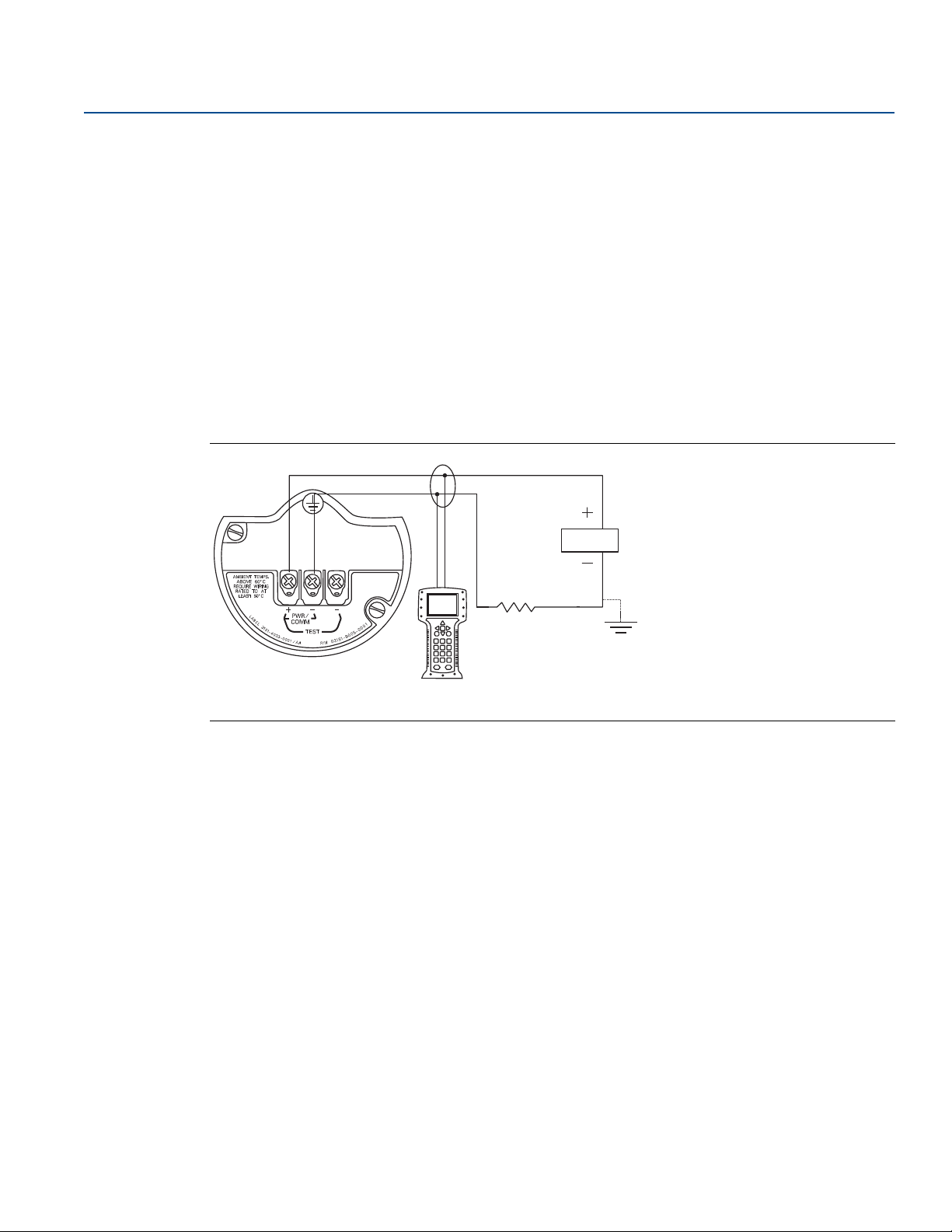
Equipment required to commission on the bench includes a power supply, a milliamp meter, and a Field
Communicator or AMS Device Manager. Wire the equipment as shown in Figure 2-1 on page 7. Verify
transmitter terminal voltage is between 10.5–42.4 Vdc. To ensure successful communication, a
resistance of at least 250 ohms must be present between the Field Communicator loop connection and
the power supply. Connect the Field Communicator leads to the terminals labeled “PWR/COMM” on the
terminal block. (Connecting across the “TEST” terminals will prevent successful communication.)
Set all transmitter hardware adjustments during commissioning to avoid exposing the transmitter
electronics to the plant environment after installation. Refer to “Wiring the device” on page 59.
When using a Field Communicator, any configuration changes made must be sent to the transmitter by
using the Send key. AMS Device Manager configuration changes are implemented when the Apply button
is selected.
2.3.1 Setting the loop to manual
Whenever sending or requesting data that would disrupt the loop or change the output of the
transmitter, set the process application loop to manual. The Field Communicator or AMS Device
Manager will prompt you to set the loop to manual when necessary. Acknowledging this prompt does
not set the loop to manual. The prompt is only a reminder; set the loop to manual as a separate
operation.
™
3051S Pressure Transmitters can be commissioned either before or after installation.
6
Configuration
Page 17
Reference Manual
A
B
00809-0100-801, Rev HA
2.3.2 Wiring diagrams
Bench hook-up
Connect the bench equipment as shown in Figure 2-1, and turn on the Field Communicator or log into
AMS Device Manager. The Field Communicator or AMS Device Manager will search for a
®
HART
-compatible device and indicate when the connection is made. If the Field Communicator or AMS
Device Manager fail to connect, it indicates that no device was found. If this occurs, refer to Section 5:
Troubleshooting.
Field hook-up
Figure 2-1 illustrate wiring loops for a field hook-up with a Field Communicator or AMS Device Manager.
The Field Communicator or AMS Device Manager may be connected at “PWR/COMM” on the transmitter
terminal block, across the load resistor, or at any termination point in the signal loop. Signal point may be
grounded at any point or left ungrounded.
Figure 2-1. Typical Wiring (4–20 mA)
Configuration
October 2018
A. Power supply
B. RL ≥ 250 Ω
Config uration
7
Page 18
Configuration
October 2018
2.4 Field Communicator
For convenience, Field Communicator Fast Key sequences are labeled “Fast Keys” for each software
function below the appropriate headings. The Device Dashboard Fast Keys apply to Device Driver
Revision 9 or newer. The HART 5 with Diagnostics Fast Keys apply to Device Driver Revision 1. The HART 7
Fast Keys apply to Device Driver Revision 2.
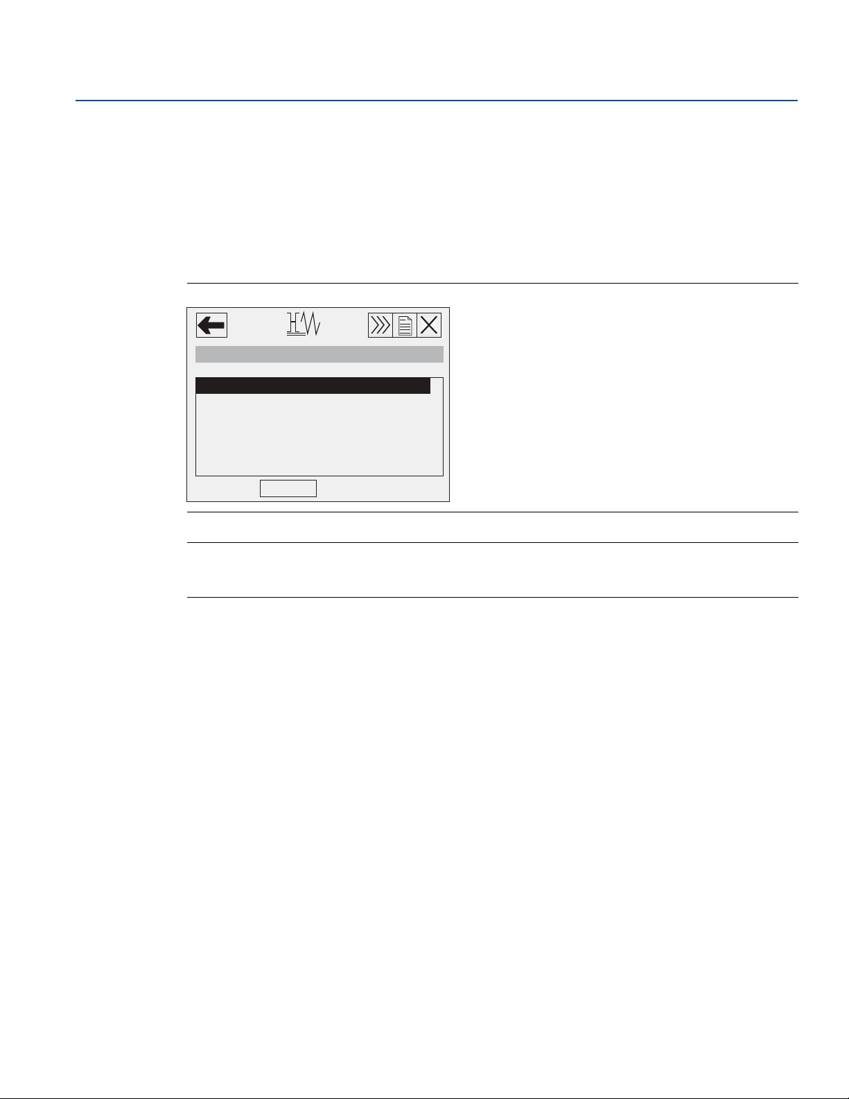
2.4.1 Field Communicator user interface
Figure 2-2. HART 5 with Diagnostics Dashboard
3051S DIAG: HDT 93207
Online
1 Overview
2 Configure
3 Service Tools
Reference Manual
00809-0100-801, Rev HA
SAVE
Note
The corresponding menu tree can be viewed on page 9.
The Fast Key sequence can be viewed on page 20.
8
Configuration
Page 19
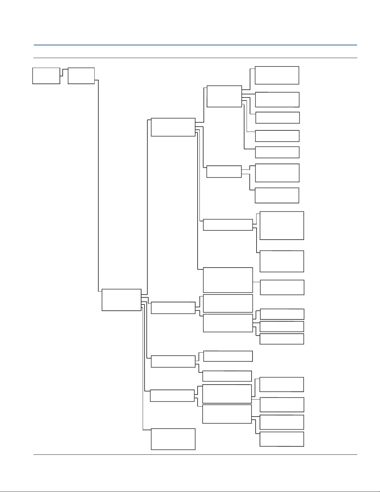
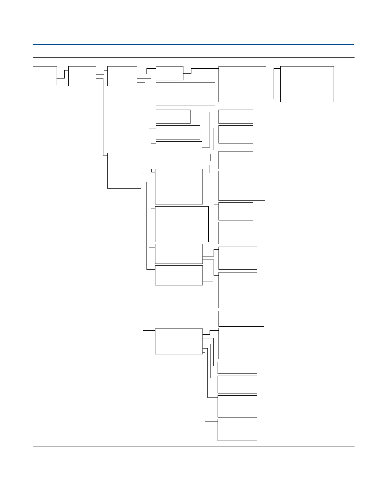
Reference Manual
Home
Overview
1 Device Status
2 Comm Status
3 Pressure
4 PV Loop Current
5 Pressure URV
6 Pressure LRV
7 Device Information
Device Information
1 Identification
2 Revisions
3 Material of Construction
4 RS Material of Construction
5 Analog Alarm
6 Security
Identification
1 Tag
2 Model
3 Transmitter S/N
4 Date
5 Description
6 Message
7 Model Number 1
8 Model Number 2
9 Model Number 3
Revisions
1 Universal Revision
2 Field Device Revision
3 Software Revision
4 Hardware Revision
5 Device Driver Revision
Materials of Construction
1 Module Configuration
2 Sensor Range
3 Upper Sensor Limit
4 Lower Sensor Limit
5 Isolator Materials
6 Fill Fluid
7 Process Connection
8 Process Connection Material
9 O-Ring Material
10 Drain Vent Material
RS Material of Construction
1 # of Remote Seals
2 RS Seal Type
3 RS Fill Fluid
4 RS Isolator Material
Analog Alarm
1 Alarm Direction
2 High Alarm
3 High Saturation
4 Low Saturation
5 Low Alarm
Security
1 Write Protect Status
2 Local Zero/Span
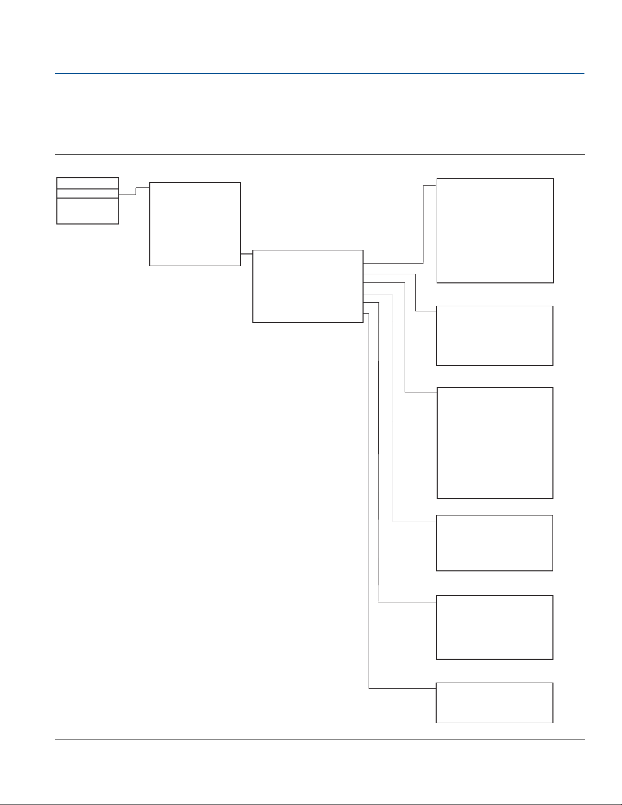
1 Overview
2 Configure
3 Service Tools
00809-0100-801, Rev HA
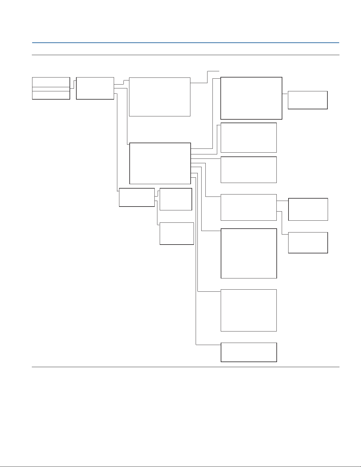
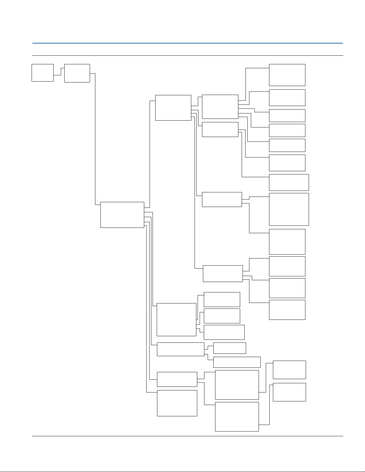
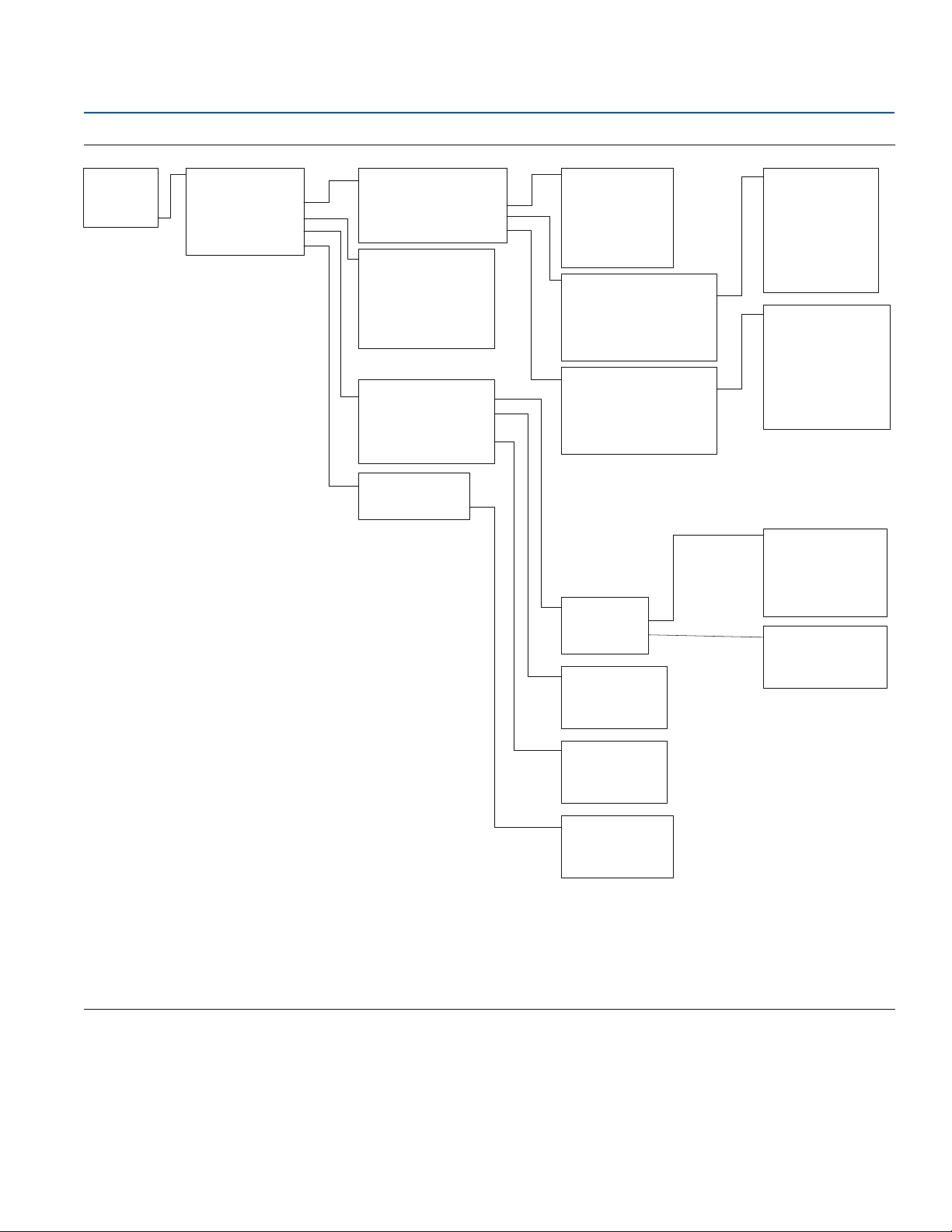
2.5 Field Communicator menu trees
2.5.1 Device Dashboard menu tree
Figure 2-3. Overview
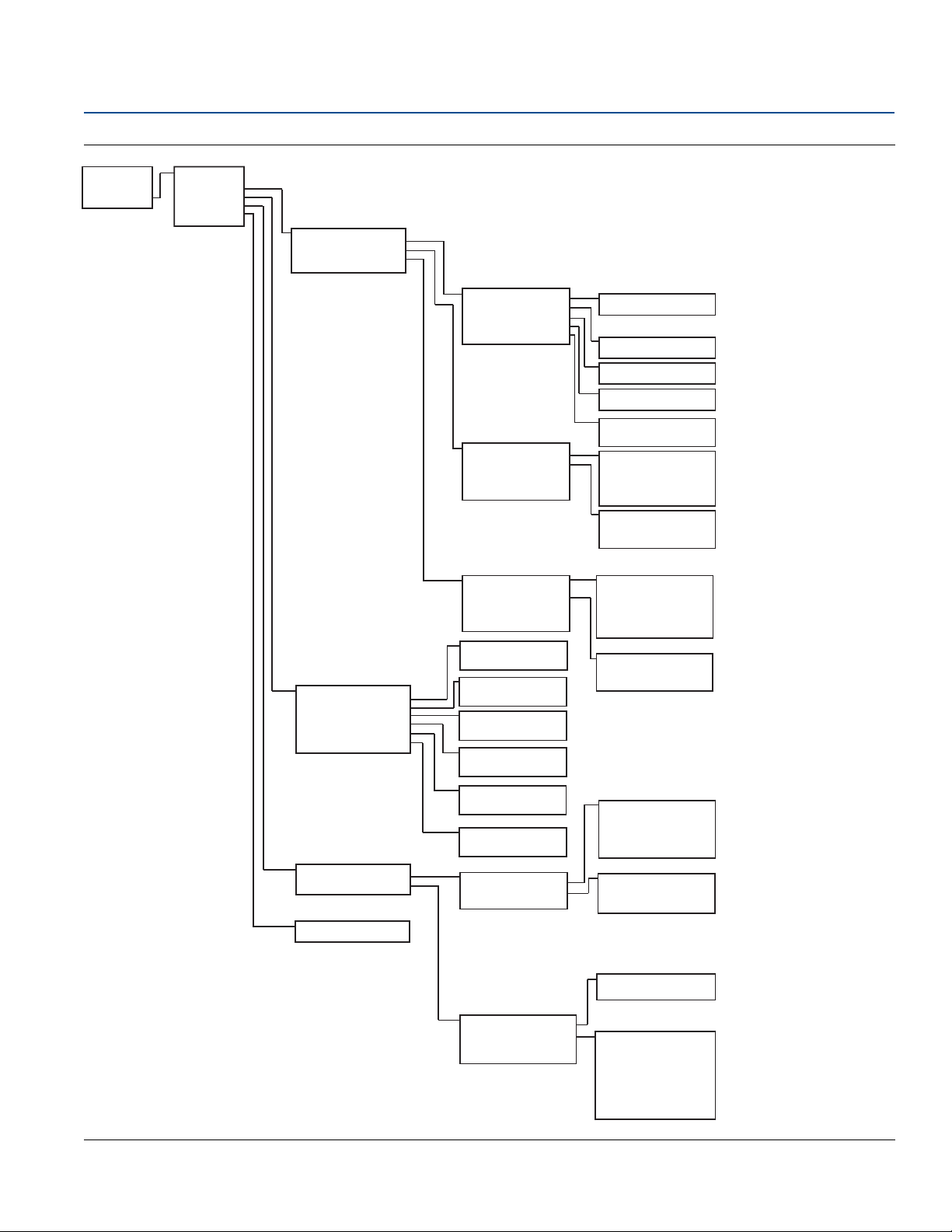
Configuration
October 2018
Config uration
9
Page 20
Home
1 Overview
2 Configure
3 Service Tools
1 Pressure Alert
2 Temperature Alert
Alert Setup
Configure
1 Guided Setup
2 Manual Setup
3 Alert Setup
Pressure Alert
1 Alert Mode
2 High Alert Value
3 Low Alert Value
Temperature Alert
1 Alert Mode
2 High Alert Value
3 Low Alert Value
Guided Setup
1 Basic Setup
2 Zero
3 Configure Display
4 Variable Mapping
5 Configure Alarm and Sat levels
6 Process Alerts
7 Scaled Variable
Manual Setup
1 Basic Setup
2 Scaled Variable
3 Display
4 HART
5 Device Information
6 Materials of Construction
7 Security
Basic Setup
1 Tag
2 Unit
3 Range Values
4 Transfer Function
5 Pressure Damping
6 Module Temperature Units
7 Configure Alarm and Sat Levels
8 Range by Applying Pressure
Scaled Variable
1 SV Data Points
2 SV Units
3 SV Transfer Function
4 SV Linear Offset
5 SV Config
Display
1 Pressure
2 Scaled Variable
3 Module Temperature
4 Percent of Range
HART
1 Variable Mapping
2 Polling Address
3 Burst Mode
4 Burst Option
Device Information
1 Tag
2 Model
3 Transmitter S/N
4 Date
5 Description
6 Message
7 Model Number 1
8 Model Number 2
9 Model Number 3
Range Values
1 Pressure URV
2 Pressure LRV
Variable Mapping
1 Primary Variable
2 Secondary Variable
3 Third Variable
Materials of Construction
1 Process Connection
2 Process Connection Material
3 Drain Vent Material
4 # of Remote Seals
5 RS Seal Type
6 RS Fill Fluid
7 RS Isolator Material
Security
1 Write Protect Status
2 Local Zero/Span
Burst Option
PV
% range/current
Dyn Vars/current
Tag, Description, Message, Date, Pressure Units,
Temperature Units, Transfer Function, URV, LRV
Configuration
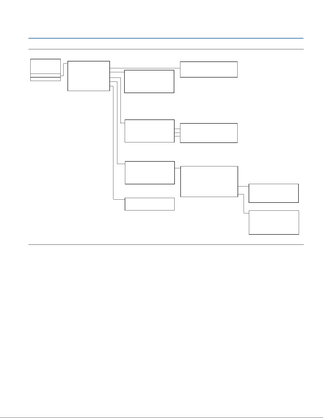
October 2018
Figure 2-4. Configure
Reference Manual
00809-0100-801, Rev HA
10
Configuration
Page 21
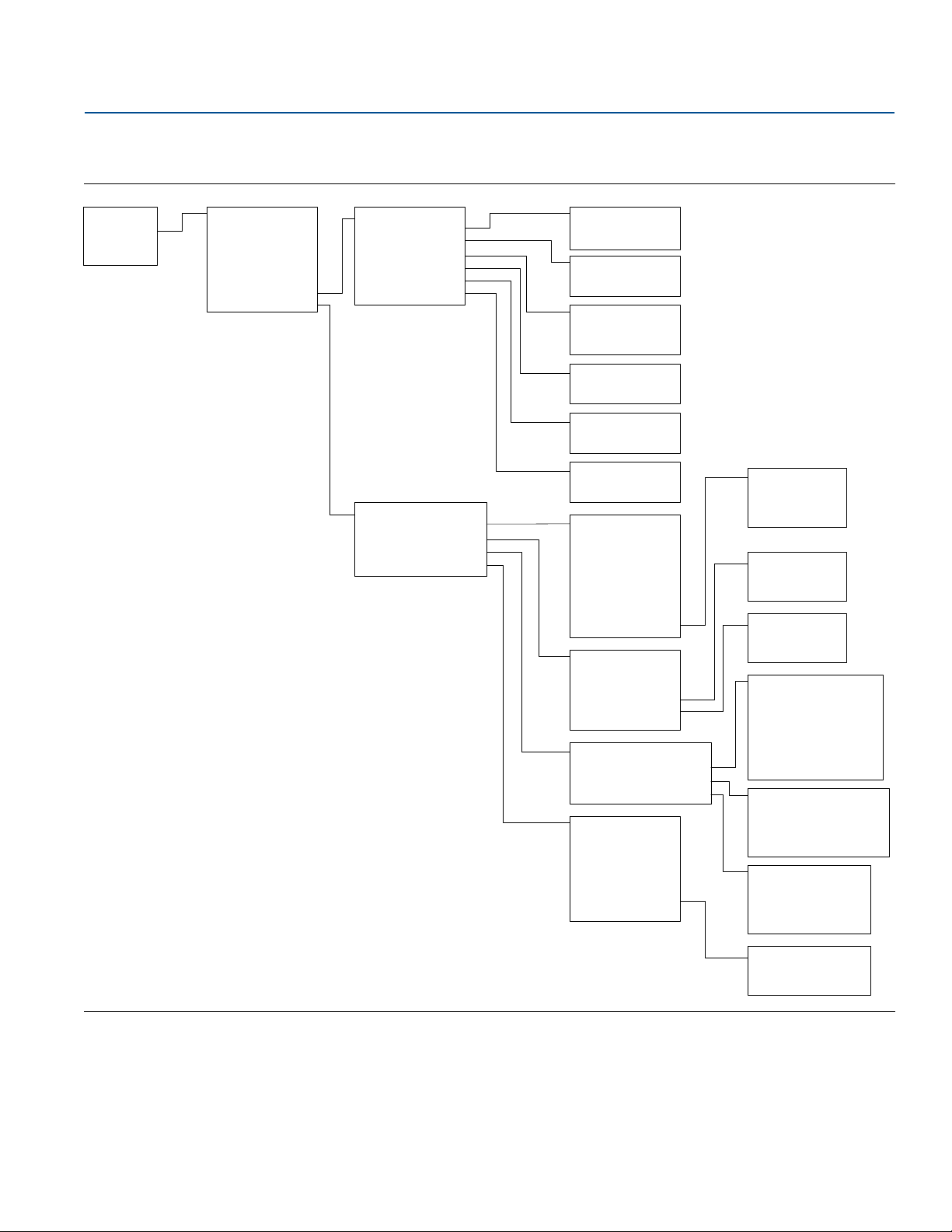
Reference Manual
Home
1 Overview
2 Configure
3 Service Tools
Service Tools
1 Device Alerts
2 Variables
3 Trends
4 Routine Maintenance
5 Simulate
Variables
1 Pressure
2 Scaled Variable
3 Module Temperature
Trends
1 Pressure
2 Scaled Variable
3 Module Temperature
Routine Maintenance
1 Pressure Calibration
2 Analog Output Calibration
3 Recall Factory Calibration
Simulate
1 Loop Test
Device Alerts
1 Refresh Alerts
2 Configuration Changed
Only Active Alerts show up
Trend Graph
Pressure Calibration
1 Upper Sensor Trim
2 Lower Sensor Trim
3 Zero
4 Last Calibration Points
5 Sensor Limits
Last Calibration Points
1 Upper Calibration Point
2 Lower Calibration Point
Sensor Limits
1 Upper
2 Lower
3 Minimum Span
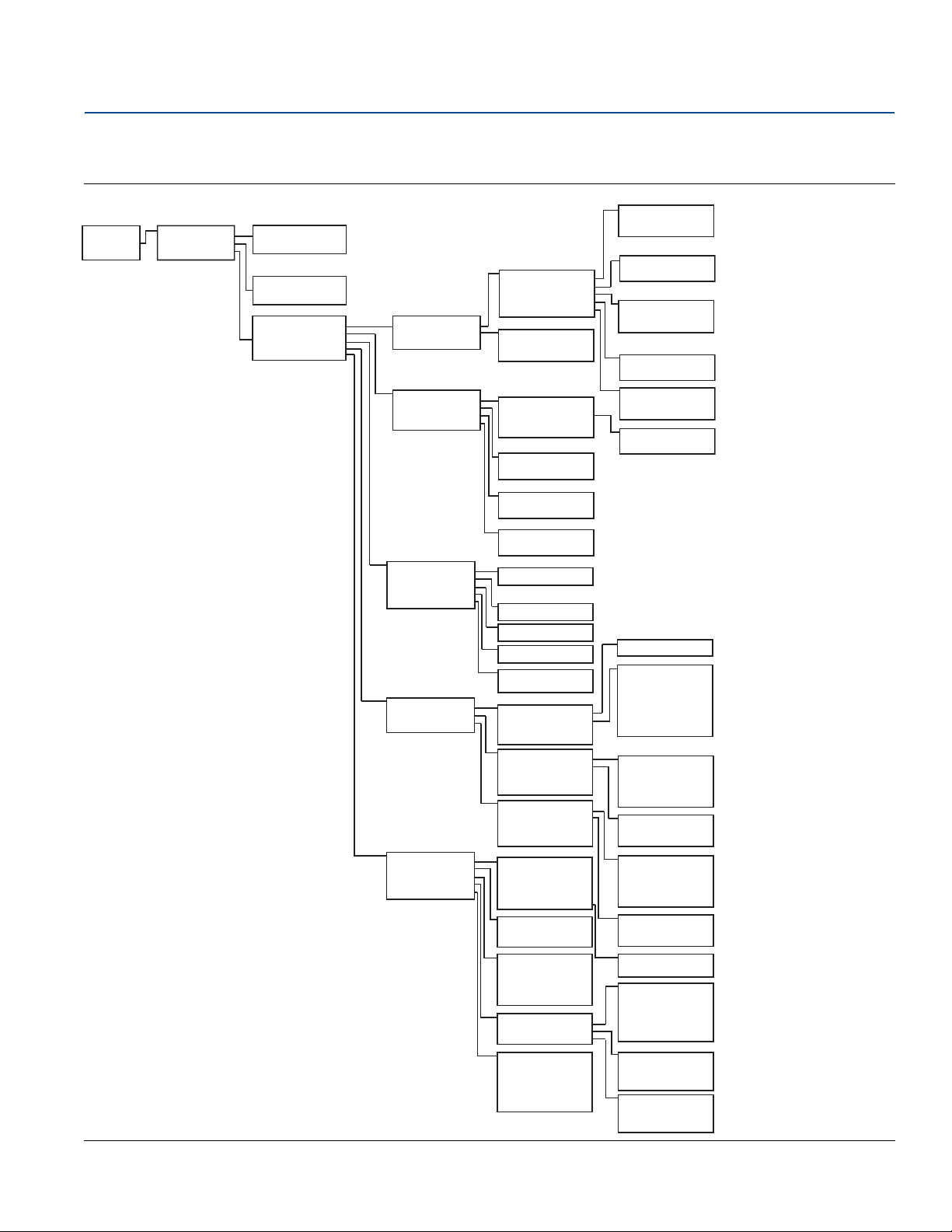
00809-0100-801, Rev HA
Figure 2-5. Service Tools
Configuration
October 2018
Config uration
11
Page 22
Home
1 Overview
2 Configure
3 Service Tools
Overview
1 Status
2 Primary Purpose Variable
3 Shortcuts
Status
1 Device Status: Good
2 Communications: Polled
Shortcuts
1 Calibration
2 SPM Status
3 All Variables
4 View Logs
5 Device Information
Calibration
1 Pressure
2 Analog Output
3 Restore Factory Calibration
Pressure
1 Sensor Calibration
2 Range Values
3 Current Measurement
4 Last Calibration Points
5 Sensor Limits
Primary Purpose Variable
1 Pressure
2 Analog Output
SPM Status
1 Detection Status
2 Statistical Values
3 Time Stamp
4 Trends
Analog Output
1 Analog Output
2 Percent of Range
3 Analog Calibration
Detection Status
1 SPM Status
2 SPM Status (cont.)
3 Standard Deviation Sensitivity*
4 Mean Sensitivity**
*If CV is selected, "Coefficient of Variation Sensitivity"
**If CV is selected, this is not shown
Statistical Values
1 Standard Deviation*
2 Mean
*Or Coefficient of Variation
Time Stamp
1 Time Since Detection
2 Total Operating Time
Trends
1 Standard Deviation*
2 Mean
*If CV is selected, "Coefficient of Variation"
All Variables
1 Primary Variable
2 2nd Variable
3 3rd Variable
4 4th Variable
5 Other Variables
Primary Variable
1 <Mapped variable>
2nd Variable
1 <Mapped variable>
3rd Variable
1 <Mapped variable>
4th Variable
1 <Mapped variable>
Other Variables
1 <Unmapped variable>
2 <Unmapped variable>
Device Information
1 General
2 Model Numbers
3 Revision Numbers
4 Materials of Construction
5 Alarm and Security
View Logs
1 Diagnostic Log
2 Pressure Variable Logging
3 Temperature Variable Logging
Diagnostic Log
1 Most Recent Status Event
2 View Other Status Events
3 Total Operating Time
4 Clear Log
Pressure Variable Logging
1 Pressure Variable Log
2 Time Outside Sensor Limits
3 Pressure
4 Total Operating Time
5 Reset All Pressure Events
Temperature Variable Logging
1 Temperature Variable Log
2 Time Outside Sensor Limits
3 Module Temperature
4 Total Operating Time
5 Reset All Temperature Events
Sensor Calibration
1 Upper Sensor Trim
2 Lower Sensor Trim
3 Zero
Range Values
1 Upper Range value (20 mA)
2 Lower Range Value (4 mA)
Current Measurement
1 Pressure
2 Damping
3 Transfer Function
Last Calibration Points
1 Upper
2 Lower
Sensor Limits
1 Upper
2 Lower
3 Minimum Span
SPM Status (cont.)
1 SPM Insufficient Variability
2 SPM Low Pressure Status
Most Recent Status Event
1 Event 1 - Time since
View Other Status Events
1 Event 2 - Time since
2 Event 3 - Time since
3 Event 4 - Time since
4 Event 5 - Time since
5 Event 6 - Time since
6 Event 7 - Time since
7 Event 8 - Time since
8 Event 9 - Time since
9 Event 10 - Time since
Pressure Variable Log
1 Minimum Pressure
2 Time Since Minimum Event
3 Reset Minimum
4 Maximum Pressure
5 Time Since Maximum Event
6 Reset Maximum
Time Outside Sensor Limits
1 Above Upper Sensor Limit
2 Below Lower Sensor Limit
3 Reset Time Since 1st Events
Temperature Variable Log
1 Minimum Temperature
2 Time Since Minimum Event
3 Reset Minimum
4 Maximum Temperature
5 Time Since Maximum Event
6 Reset Maximum
Time Outside Sensor Limits
1 Above Upper Sensor Limit
2 Below Lower Sensor Limit
3 Reset Time Since 1st Events
General
1 Tag
2 Model
3 Date
4 Descriptor
5 Message
6 Serial Number
Model Numbers
1 Model Number 1
2 Model Number 2
3 Model Number 3
Revision Numbers
1 HART Universal
2 Field Device
3 Electronics SW
4 Electronics HW
5 Sensor SW
6 Sensor HW
Materials of Construction
1 Sensor Module Information
2 Flange Information
3 Remote Seal Information
Alarm and Security
1 Alarm Direction
2 High Alarm
3 High Saturation
4 Low Saturation
5 Low Alarm
6 Write Protect Status
7 Local ZERO/SPAN Buttons
Serial Number
1 Transmitter
2 Electronics
Sensor Module Information
1 Serial Number
2 Type
3 Configuration
4 Sensor Range
5 Sensor Limits
6 Isolator Material
7 Fill Fluid
Flange Information
1 Process Connection
2 Process Connection Material
3 O-ring Material
4 Drain Vent Material
Remote Seal Information
1 Number
2 Type
3 Diaphragm Material
4 Fill Fluid
Configuration
October 2018
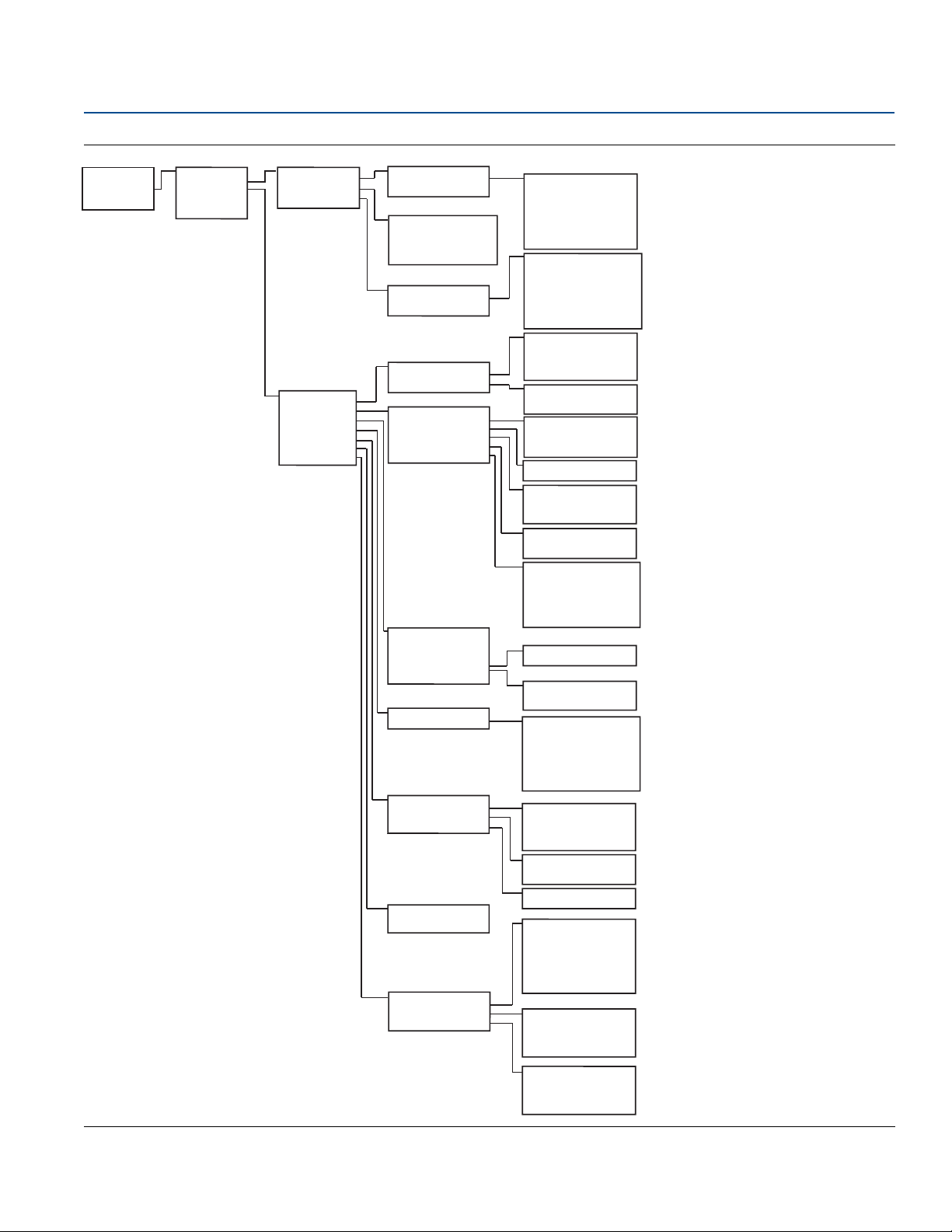
2.5.2 HART 5 with Diagnostic menu trees
Figure 2-6. Overview
12
Reference Manual
00809-0100-801, Rev HA
Configuration
Page 23
Reference Manual
Home
1 Overview
2 Configure
3 Service Tools
Configure
1 Guided Setup
2 Manual Setup
3 Alert Setup
(see Figure 7-33)
Guided Setup
1 Initial Setup
2 Diagnostics Setup
3 Optional Configuration
Manual Setup
1 Process Variables
2 Analog Output
3 Scaled Variable
4 Display Options
5 HART
6 Security
7 Device Information
Initial Setup
1 Basic Setup
2 Zero Trim
Diagnostics Setup
1 Statistical Process Monitoring
2 Power Advisory
3 Process Alerts
4 Service Alert
Optional Configuration
1 Configure Display
2 Configure Burst Mode
Basic Setup
1 Device Tagging
2 Units of Measure
3 Pressure Damping
4 Variable Mapping
5 Analog Output
6
Config Alarm & Saturation Levels
Display Options
1 Pressure: On or Off
2 Scaled Variable: On or Off
3 Module Temperature: On or Off
4 Percent of Range: On or Off
5 Standard Deviation: On or Off
6 Mean: On or Off
7 Coefficient of Variation: On or Off
Process Variables
1 Pressure Setup
2 Module Temperature Setup
Analog Output
1 Set Range Points
2 Set Range Points Manually
3 Sensor Limits
4 Readings
5 Alarm and Saturation Levels
Pressure Setup
1 Pressure
2 Units
3 Damping
4 Transfer Function
Module Temperature Setup
1 Module Temperature
2 Units
Set Range Points
1 PV Upper Range Value
2 PV Lower Range Value
3 Primary Variable
Set Range Points Manually
1 Range By Applying Pressure
Sensor Limits
1 Upper
2 Lower
3 Minimum Span
Readings
1 Analog Output
2 Percent of Range
Alarm and Saturation Levels
1 Alarm Direction
2 High Alarm
3 High Saturation
4 Low Saturation
5 Low Alarm
6 Config Alarm & Saturation Levels
Scaled Variable Setup
1 Scaled Variable
2 Units
3 Transfer Function
4 Linear Options*
5 Configure Scaled Variable
*If Square Root is selected for Transfer Function,
"Square Root Options"
Linear Options
1 Offset
Square Root Options
1 Cutoff Mode
2 Low Flow Cutoff
Display
1 Display Options
Display Options
1 Pressure: On or Off
2 Scaled Variable: On or Off
3 Module Temperature: On or Off
4 Percent of Range: On or Off
5 Standard Deviation: On or Off
6 Mean: On or Off
7 Coefficient of Variation: On or Off
HART
1 Variable Mapping
2 Burst Mode Configuration
3 Communication Settings
Variable Mapping
1 Primary Variable
2 2nd Variable
3 3rd Variable
4 4th Variable
Burst Mode Configuration
1 Mode
2 Option
Communication Settings
1 Polling Address
Security
1 Write Protect Status
2 Local ZERO/SPAN Buttons
Device Information
1 Identification
2 Flange Information
3 Remote Seal Information
Identification
1 Tag
2 Model
3 Date
4 Descriptor
5 Message
6 Transmitter Serial Number
7 Model Numbers
Flange Information
1 Process Connection
2 Process Connection Material
3 O-ring Material
4 Drain/Vent Material
Remote Seal Information
1 Number
2 Type
3 Diaphragm Material
4 Fill Fluid
00809-0100-801, Rev HA
Figure 2-7. Configure (Guided Setup and Manual Setup)
Configuration
October 2018
Config uration
13
Page 24
Configuration
Home
1 Overview
2 Configure
3 Service Tools
Configure
1 Guided Setup
2 Manual Setup
3 Alert Setup
Alert Setup
1 Statistical Process
Monitoring
2 Power Advisory Diagnostic
3 Device Diagnostics
4 Process Alerts
5 Service Alerts
Statistical Process Monitoring
Status
Baseline Configuration
Detection Configuration
Operational Values
Status
1 Detection Status
2 SPM Control
3 Statistical Values
4 Time Stamp
5 Trends
Detection Status
1 SPM Status
2 SPM Status (cont.)
3 Standard Deviation Sensitivity*
4 Mean Sensitivity**
*If CV is selected, "Coefficient of Variation Sensitivity"
**If CV is selected, this is not shown
SPM Control
1 Mode
2 Reset
3 Relearn
Statistical Values
1 Standard Deviation*
2 Mean
*Or Coefficient of Variation
Time Stamp
1 Time Since Detection
2 Total Operating Time
Trends
1 View Standard Deviation Trend*
2 View Mean Trend
*Or Coefficient of Variation
Baseline Configuration
1 Learn Settings
2 Verification Criteria
Learn Settings
1 SPM Variable
2 Learn/Monitor Period
3 Power Interruption Action
4 Low pressure Cut-off *
*Shown only when CV is selected
Verification Criteria
1 Insufficient Variability
2 Standard Deviation Difference
3 Mean Difference
Detection Configuration
1 Standard Deviation Detection Settings*
2 Mean Detection Settings**
*If CV is selected, "Coefficient of Variation
Detection Settings"
**If CV is selected, this is not shown
Standard Deviation Change*
1 Standard Deviation Sensitivity
2 Threshold Value**
3 Configure Sensitivity
4 Action
5 Alert Delay
6 High Detection Message
7 Low Detection Message
* If CV is selected, “Coefficient of Variation Change”
**Shown only if Sensitivity is set to "Custom"
Mean Change**
1 Mean Sensitivity
2 Threshold Value
3 Configure Sensitivity
4 Action
5 Mean Change Message
**If CV is selected, this is not shown
Operational Values
1 Standard Deviation
2 Mean
3 Coefficient of Variation
4 SPM Detection Values
5 Number of Relearns
6 Reset Relearn Counter
SPM Detection Values
1 Standard Deviation
2 Mean
3 Coefficient of Variation
Power Advisory Diagnostic
1 Power Advisory Diagnostic
2 Loop Power Characterization
Power Advisory Diagnostic
1 Terminal Voltage
2 Terminal Voltage Deviation Limit
3 Action
4 Reset Alert
Loop Power Characterization
1 Resistance
2 Power Supply
3 Characterization Time Stamp
4 Characterize Loop
Resistance
1 Previous Baseline
2 Baseline
Power Supply
1 Previous Baseline
2 Baseline
Characterization Time Stamp
1 Previous Characterization
2 Time Since Characterization
Device Diagnostics
1 mA Output Diagnostic
2 Transmitter Power Consumption
mA Output Diagnostic
1 Action
2 Reset Alert
Transmitter Power Consumption
1 Action
2 Reset Alert
Process Alerts
1 Pressure Alerts
2 Temperature Alerts
Pressure Alerts
1 View Trend
2 Pressure
3 Alert Settings
4 Pressure Alert Events
Temperature Alerts
1 View Trend
2 Module Temperature
3 Alert Settings
4 Module Temperature Alert Events
Service Alerts
1 Time Remaining
2 Message
3 Alert Mode
4 Configure
5 Reset Alert
Alert Settings
1 Alert Mode
2 High Alert Value
3 Low Alert Value
Pressure Alert Events
1 High Alert Events
2 Low Alert Events
3 Reset Alert Events
Alert Settings
1 Alert Mode
2 High Alert Value
3 Low Alert Value
Temperature Alert Events
1 High Alert Events
2 Low Alert Events
3 Reset Alert Events
October 2018
Figure 2-8. Configure (Alert Setup)
Reference Manual
00809-0100-801, Rev HA
14
Configuration
Page 25
Reference Manual
Home
1 Overview
2 Configure
3 Service Tools
Service Tools
1 Device Alerts
2 Variables
3 Trends
4 Maintenance
5 Simulate
View Variables
1 Primary Variable
2 2nd Variable
3 3rd Variable
4 4th Variable
5 Other Variables
Variables
1 All Variables
2 Pressure Variable Logging
3 Temperature Variable Logging
Pressure Variable Logging
1 Pressure Variable Log
2 Time Outside Sensor Limits
3 Pressure
4Total Operating Time
5 Reset All Pressure Events
Primary Variable
1 <Mapped variable>
2nd Variable
1 <Mapped variable>
3rd Variable
1 <Mapped variable>
4th Variable
1 <Mapped variable>
Other Variables
1 <Unmapped variable>
2 <Unmapped variable>
Pressure Variable Logging
1 Pressure Variable Log
2 Time Outside Sensor Limits
3 Pressure
4 Total Operating Time
5 Reset All Pressure Events
Time Outside Sensor Limits
1 Above Upper Sensor Limit
2 Below Lower Sensor Limit
3 Reset Time Since 1st Events
Temperature Variable Logging
1 Temperature Variable Log
2 Time Outside Sensor Limits
3 Module Temperature
4 Total Operating Time
5 Reset All Temperature Events
Temperature Variable Log
1 Minimum Temperature
2 Time Since Minimum Event
3 Reset Minimum
4 Maximum Temperature
5 Time Since Maximum Event
6 Reset Maximum
Time Outside Sensor Limits
1 Above Upper Sensor Limit
2 Below Lower Sensor Limit
3 Reset Time Since 1st Events
Trends
Pressure
Module Temperature
Scaled Variable
Standard Deviation
Mean
Coefficient of Variation
Maintenance
Calibration
Diagnostic Log
Pressure
1 View Trend
2 Pressure
Module Temperature
1 View Trend
2 Module Temperature
Scaled Variable
1 View Trend
2 Scaled Variable
Standard Deviation
1 View Trend
2 Standard Deviation
Mean
1 View Trend
2 Mean
Coefficient of Variation
1 View Trend
2 Coefficient of Variation
Simulate
Loop Test
Calibration
1 Pressure
2 Analog Output
3 Restore Factory Calibration
Pressure
1 Sensor Calibration
2 Range Values
3 Current Measurement
4 Last Calibration Points
5 Sensor Limits
Analog Output
1 Analog Output
2 Percent of Range
3 Analog Calibration
Diagnostic Log
1 Most Recent Status Event
2 View Other Status Events
3 Total Operating Time
4 Clear Log
Most Recent Status Event
1 Event 1 - Time since
View Other Status Events
1 Event 2 - Time since
2 Event 3 - Time since
3 Event 4 - Time since
4 Event 5 - Time since
5 Event 6 - Time since
6 Event 7 - Time since
7 Event 8 - Time since
8 Event 9 - Time since
9 Event 10 - Time since
00809-0100-801, Rev HA
Figure 2-9. Service Tools
Configuration
October 2018
Config uration
15
Page 26
Configuration
Home
1 Overv iew
2 Configure
3 Serv ic e Tools
Overview
1 Device Status: Good
2 Co mm Stat us: Bu rst
3 Pr essu re
4 Statu s
5 Analog Out pu t
6 All Variab les
7 Device Informat ion
All Variables
1 Primary Variable
2 Secondary Variable
3 Thir d Variable
4 Fou rt h Variable
5 Per cent o f Range
6 Analo g Out pu t
Device Information
1 Identification
2 Revisions
3 Materials of Construction
4 Ala rm an d Sec urit y
Primary Variable
1 <Mapped Variable>
2 Gau ge
Secondary Var iable
1 <Mapped Variable>
2 Gau ge
Thir d Variab le
1 <Mapped Variable>
2 Gau ge
Fourth Variable
1 <Mapped Variable>
2 Gau ge
Percent of Range
1 Per cen t o f Range
2 Gau ge
Anal og Ou tpu t
1 Analo g Out pu t
2 Gau ge
Identification
1 Tag
2 Lon g Tag
3 Mod el
4 Serial Nu mb er
5 Dat e
6 Desc rip tion
7 Message
8 Mod el Numb ers
Mod el Nu mbers
1 Mod el Numb er 1
2 Mod el Numb er 2
3 Mod el Numb er 3
Revisions
1 Universal Revision
2 Field Device Rev
3 Elect ro nic s
4 Sensor
5 DD Revision
Electronics
1 Softw are Rev ision
2 Har dware Revision
Sensor
1 Softw are Rev ision
2 Har dware Revision
Materials Of Construction
1 Sen sor Modu le Infor matio n
2 Flange Inform ation
3 Remot e Seal In formatio n
Sensor Module Informati on
1 Serial Nu mber
2 Typ e
3 Co nfigu r atio n
4 Sensor Range
5 Sensor Limits
6 Isolator Material
7 Fill Fluid
Flange Information
1 Process Connection
2 Process Connection Material
3 O-rin g Material
4 Drain/Vent Material
Remote Seal I nformati on
1Number
2 Typ e
3 Diaphragm Material
4 Fill Fluid
Alar m an d Secu rit y
1 Alarm Direc tio n
2 High Alarm
3 High Saturation
4 Low Satu ration
5 Low Alar m
6 Sec ur ity
7 HAR T Lock
Security
1 Write P ro tec t
2 ZERO/SP AN But ton s
October 2018
2.5.3 HART 7 menu trees
Figure 2-10. Overview
Reference Manual
00809-0100-801, Rev HA
16
Configuration
Page 27
Reference Manual
Home
1 Over view
2 Co nfig ur e
3 Ser vic e Too ls
Configure
1 Gu ided Setu p
2 Manu al Set up
3 Alert Setup
Guided Setup
1 Init ial Setu p
2 Diagn ostic s Setu p
3 Optional Setup
Initial Setup
1 Basic Setup
2 Zero
Basic Setup
1 Device Tagging
2 Pressure Setup
3 Mod ule Temp eratu re Setu p
4 Var iable Mapp ing
5 Ana log Outp ut
6 Co nfigu re Alar m/Sat
7 Dis play Opt ions
Di agnost ics Setup
1 Stat istical Proc ess Monito ring (SPM)
2 Power Advisory
3 Pr ocess Alert s
4 Ser vic e Alerts
Optional Setup
1 Con fig Sca led Var
2 Bur st Con figurat ion
Manua l Set up
1 Pr ocess Varia bles
2 Analo g Outp ut
3 Scaled Variab le
4 Disp lay Option s
5 HART
6 Secu rity
7 Devic e Info rmatio n
Process Variables
1 Pr essure Setu p
2 Mod ule Tempera tu re Set up
Display Options
1 Pr essure: On or Off
2 Sc aled Variab le : On or Off
3 Mo du le Temper atu re: On o r Off
4 Per cent of Range: On or Off
5 S tand ard Deviatio n: On o r Off
6 Mean: On or Off
7 C oeffic ient o f Variat ion : On or Off
Anal og Ou tp ut
1 Readin gs
2 Con figurat ion
3 Range by Applying Pressure
4 Senso r Limit s
5 Alarm and Sat urat ion Levels
Readin gs
1 Ana log Outp ut
2 Per cent of Rang e
Configuration
1 U pp er R ange Value
2 Low er Range Value
3 PV
Sensor Li mits
1 Up per
2 Low er
3 Minimum Span
Alarm and S aturat io n Level s
1 Alar m Dir ecti on
2 Hig h Alar m
3 High Saturation
4 Low Saturation
5 Low Alar m
6 Co nfigu re Alar m/Sat
Scaled Vari able
1 Scaled Variable
2 Un its
3 Tra nsf er Fun c tio n
4 Linea r Opt ion s
5 Sen sor Limit s
6 Data Points
7 C onf ig Sca led Var
Sensor Li mits
1 Up per
2 Low er
3 Minimum Span
Display Options
1 Pr essure: On o r Off
2 Sc aled Variable: On or Off
3 Module Temperature: On or Off
4 Percent of Range: On or Off
5 St andard Deviation: On or Off
6 Mean: On or Off
7 C oeffic ient of Variat ion : On or Off
HART
1 Var iabl e Mappin g
2 Communication Settings
3 Bu rst Con figu ratio n
Security
1 Writ e Pro tec t
2 ZER O/SP AN Bu t to ns
3 HAR T Lock
Device Information
1 Id ent ificat ion
2 Ser ial Num ber
3 Mod el Num ber s
4 Flange Infor matio n
5 Remot e Seal Infor matio n
Vari abl e Mapp ing
1 PV
2 SV
3 TV
4 QV
Communication Settings
1 Polling Address
2 C han ge Po ll Add ress
3 Un iver sal Revisio n
4 C han ge HAR T Rev
Burst Configuration
1 Bu rst Mo de
2 Bu rst Co mman d
3 Burst Variable 1
4 Burst Variable 2
5 Burst Variable 3
6 Burst Variable 4
7 Config Add’l Msgs
HART Lock
1 Device is Locked: On or Off
2 Loc k/Un loc k
Identification
1 Tag
2 Lon g Tag
3 Mod el
4 Dat e
5 Des cr ipt ion
6 Messa ge
Serial Nu mber
1 F inal Asse mbly Num
Mod el Num ber s
1 Mo del Nu mb er 1
2 Mo del Nu mb er 2
3 Mo del Nu mb er 3
Flan ge In format io n
1 Pr oc ess Con nec tio n
2 Pr oc ess Con nec tio n Mat
3 O- ring Material
4 Drain/V ent Material
Remot e Seal I nfor mati on
1 Nu mb er
2 Typ e
3 Diaphr agm Material
4 Fill Fluid
00809-0100-801, Rev HA
Figure 2-11. Configure (Guided Setup and Manual Setup)
Configuration
October 2018
Config uration
17
Page 28
Configuration
Home
1 Over view
2 Co nfig ur e
3 Ser vic e Tools
Configure
1 Guid ed Setup
2 Manual Setu p
3 Alert Setup
Alert Setup
1 S tat istic al Pr oces s Mon itor ing
2 Power Advisory Diagnostic
3 Device Diagnostics
4 Proc ess Alert s
5 Ser vic e Alerts
Statistical Process
Mon it or in g
1 SPM Status
2 Baseline Configu ratio n
3 Detection Configuration
4 Oper ation al Valu es
SPM Status
1 Det ectio n St atus
2 SP M Con tr ol
3 St atis tic al Valu es
4 Time St amp
5 Tren ds
Detection Status
1 SP M Stat us
2 In suff Varia bility
3 Std Dev Sensitivity
4 Mean Sensitivit y
SPM Contro l
1 SPM Mod e
2 Reset
3 Relea rn
Statisti cal Values
1 Standard Deviation
2 Mean
Time S tamp
1 Time Sinc e Det ected
2 Oper atin g Time
Trends
1 Standard Deviation
2 Mean
Baseline Configuration
1 Learn Settings
2 Veri fica tio n Crit eria
Learn Settings
1 SP M Variab le
2 Lrn/Monitor Period
3 Power Interrupt Act
Veri ficat ion Cri teri a
1 I nsu ff Varia bilit y: On or Off
2 Std Dev Differen ce
3 Mean Differ ence
Detection Configuration
1 St andard Deviation C hange
2 Mean Change
Operational Values
1 Stand ard Deviatio n
2 Mean
3 Coefficient of Variation
Standard Deviati on Change
1 Std Dev Sensitivity
2 Thr eshold Valu e
3 Conf ig Sensitivity
4 Act ion
5 Alert D elay
6 Hig h Det ect ion Msg
7 Low Detec tion Msg
Mean Cha nge
1 Mean Sensitivit y
2 Thr eshold Valu e
3 Conf ig Sensitivity
4 Act ion
5 Mean Change Msg
Standard Deviation
1 Standard Deviation
2 Base line
3 Upper Threshold
4 Lower Threshold
Mean
1 Mean
2 Base line
3 Upper Threshold
4 Lower Threshold
Coeffici ent of Vari ation
1 Coeff of Variation
2 Base line
3 Upper Threshold
4 Lower Threshold
Power Advisory Diagnostic
1 Terminal Voltage
2 Dev iati on Limi t
3 Act ion
4 Resistance
5 Power Supply
6 Time St amp
7 Charac terize Loop
Resistance
1 Baseline
2 Pr eviou s Bas eline
Power Supply
1 Baseline
2 Pr eviou s Bas eline
Time Stamp
1 Time Since Charac terizat ion
2 Previo us Char acterizatio n
Device Diagnostics
1 mA Output Diagnostic
2 Transmitter Power Consumption
mA Output Di agnostic
1 Act ion
Transmitter Power Consumption
1 Act ion
Pro cess Alerts
1 Pressur e Alerts
2 Temp eratur e Alert s
Pressure Alerts
1 Alert Mod e
2 High Alert Valu e
3 Low Aler t Value
4 Pressure
5 Alert Events
6 View Trend
Temp eratu re Aler ts
1 Alert Mod e
2 High Alert Valu e
3 Low Aler t Value
4 Pressure
5 Alert Events
6 View Trend
Alert Events
1 H igh Aler t Ev ents
2 Lo w Alert Even ts
3 Reset Alert Events
Alert Events
1 H igh Aler t Ev ents
2 Lo w Alert Even ts
3 Reset Alert Events
Service Alerts
1 Time Remainin g
2 Message
3 Alert Mode
4 Configure
5 Reset Alert
October 2018
Figure 2-12. Configure (Alert Setup)
Reference Manual
00809-0100-801, Rev HA
18
Configuration
Page 29
Reference Manual
Home
1 Over v iew
2 Co nfigu r e
3 Ser vic e Too ls
Service Tools
1 Alert s
2 Variables
3 Trends
4 Maintenance
5 Simulate
Vari ables
1 Var iable Su m mar y
2 All Variab les
3 Pr essu re Var iab le Logging
4 Temperat ur e Variable Logging
Trends
1 Pr essu re
2 Module Temperature
3 Sc aled Variab le
4 Standard Deviation
5 Mean
6 Coefficient of Variat ion
Mai nten ance
1 Calib ration
2 Sec urit y
3 Locate Device
4 Diagno st ic Log
5 Reset/Restore
Simul ate
1 Loop Test
2 Dev ice Variab les
Calibration
1 Pr essu re
2 Analog Output
3 Rest ore
All Vari abl es
1 Primary Variable
2 Secondary Variable
3 Thir d Variable
4 Four th Variab le
5 Per cent of Range
6 Analog Output
Pressure
1 Sensor Calibration
2 Range Valu es
3 Current Measu rem ent
4 Last Calibration Points
5 Sen so r Lim it s
Analog Output
1 Analog Out put
2 Per cent of Rang e
3 Analog Calib ra tion
Security
1 Write Protect
2 ZERO/SP AN Bu t tons
3 HAR T Lock
Diagnostic Log
1 Status Even ts
2 Oper at ing Time
3 Clear Log
Device Variables
1 Pr essu re
2 Module Temperature
3 Scaled Variable
Pressure Variable Logging
1 Pr essu re Variab le Log
2 Time Above Upper Sensor Limit
3 Time Below Lower Sensor Limit
4 R eset Tim e Sinc e 1
st
Event s
5 R eset All Pr essur e Ev ents
Temp eratu re Var iabl e Lo ggin g
1 Tem pera ture V ariable Lo g
2 Time Above Upper Sensor Limit
3 Time Below Lower Sensor Limit
4 R eset Tim e Sinc e 1
st
Event s
5 R eset All Pr essur e Ev ents
Pressure Variable Log
1 Minimu m Pressure
2 Time Since Even t
3 Reset Minimu m
4 Max imum Pressu re
5 Time Since Even t
6 Reset Max imum
7 Pr essur e
8 Operating Tim e
Temp eratu re Variabl e Log
1 Minimum Temperature
2 Time Since Even t
3 Reset Minimu m
4 Maximum Temperature
5 Time Since Even t
6 Reset Max imum
7 Modu le Temp erat ur e
8 Operating Tim e
00809-0100-801, Rev HA
Figure 2-13. Service Tools
Configuration
October 2018
Config uration
19
Page 30

Configuration
October 2018
2.5.4 Device Dashboard Fast Key sequence
The following menu indicates Fast Key sequences for common functions. A check () indicates the basic
configuration parameters. At minimum, these parameters should be verified as part of the configuration
and startup procedure.
Function Fast Key sequence
Alarm and Saturation Levels 1, 4, 5
Alarm Level Configuration 1, 7, 5
Analog Output Alarm Direction 1, 7, 5, 1
Burst Mode Control 2, 2, 4, 3
Burst Option 2, 2, 4, 4
Custom Display Configuration 2, 1, 3
Damping 2, 2, 1, 5
Date 2, 2, 5, 4
Descriptor 2, 2, 5, 5
Digital to Analog Trim (4 - 20 mA Output) 3, 4, 2
Disable Zero & Span Adjustment 2, 2, 7, 2
Field Device Information 1, 7
LCD Display Configuration 2, 2, 3
Loop Test 3, 5, 1
Lower Sensor Trim 3, 4, 1, 2
Message 2, 2, 5, 6
Mod ule Temperature/Tr end 3, 3, 3
Poll Address 1, 2, 2
Pressure Alert Configuration 2, 3, 1
Range Values 2, 2, 1, 3
Re-mapping 2, 2, 4, 1
Rerange - Keypad Input 1, 5
Rerange with Keypad 2, 2, 1, 3
Saturation Level Configuration 2, 2, 1, 7
Scaled D/A Trim (4–20 mA Output) 3, 4, 2
Scaled Variable Configuration 2, 2, 2
Sensor Information (Materials of Construction) 1, 7, 3
Sensor Trim 3, 4, 1
Sensor Trim Points 3, 4, 1, 4
Ta g 2, 2, 5, 1
Temperature Alert Configuration 2, 3, 2
Transfer Function (Setting Output Type) 2, 2, 1, 4
Transmitter Security (Write Protect) 2, 2, 7, 1
Units (Process Variable) 2, 2, 1, 2
Upper Sensor Trim 3, 4, 1, 1
Zero Trim 3, 4, 1, 3
Reference Manual
00809-0100-801, Rev HA
20
Configuration
Page 31

Reference Manual
00809-0100-801, Rev HA
2.5.5 HART 5 with Diagnostics Fast Key sequence
The following menu indicates Fast Key sequences for common functions. A check () indicates the basic
configuration parameters. At minimum, these parameters should be verified as part of the configuration
and startup procedure.
Function Fast Key sequence
Alarm and Saturation Levels 2, 2, 2, 5
Alarm Level Configuration 2, 1, 1, 1, 6
Analog Output Alarm Direction 2, 2, 2, 5, 5, 1
Burst Mode On/Off 2, 2, 5, 2, 1
Burst Option 2, 2, 5, 2, 2
Damping
Date 2, 2, 7, 1, 3
Descriptor 2, 2, 7, 1, 4
Digital to Analog Trim (4–20 mA Output) 3, 4, 1, 2, 3
Field Device Information 1, 3, 5
LCD Display Configuration 2, 2, 4
Loop Test 3, 5
Lower Sensor Trim 3, 4, 1, 1, 1, 2
Message 2, 2, 7, 1, 5
Module Temperature 2, 2, 1, 2
Poll Address 2, 2, 5, 3, 1
Pressure Alert Configuration 2, 3, 4, 1, 3
Range Values 3, 4, 1, 1, 2
Re-mapping 2, 2, 5, 1
Rerange - Keypad Input 2, 2, 2, 1
Rerange with Pressure Source 2, 2, 2, 2
Saturation Level Configuration 2, 1, 1, 1, 6
Scaled Variable Configuration 2, 2, 3, 5
Sensor Information 1, 3, 5, 4, 1
Sensor Trim Points 1, 3, 1, 1, 4
Ta g
Temperature Alert Configuration
Transfer Function (Setting Output Type)
Transmitter Security (Write Protect) 1, 3, 5, 5, 6
Units (Process Variable)
Upper Sensor Trim 3, 4, 1, 1, 1, 1
Zero Trim 3, 4, 1, 1, 1, 3
2, 2, 1, 1, 3
2, 2, 7, 1, 1
2, 3, 4, 2, 3
2, 2, 1, 1, 4
2, 2, 1, 1, 2
Configuration
October 2018
Config uration
21
Page 32

Configuration
October 2018
2.5.6 HART 7 Fast Key sequence
Function Fast Key sequence
Alarm and Saturation Levels 2, 2, 2, 5
Alarm Level Configuration 2, 2, 2, 5, 6
Analog Output Alarm Direction 2, 2, 2, 5, 1
Burst Mode Control 2, 2, 5, 3
Burst Option 2, 2, 5, 3, 1
Damping 2, 2, 1, 1, 3
Date 2, 2, 5, 4
Descriptor 2, 2, 7, 1, 4
Digital to Analog Trim (4–20 mA Output) 3, 4, 1, 2, 3, 1
Disable Zero & Span Adjustment 2, 2, 6, 4
Field Device Information 1, 7
LCD Display Configuration 2, 2, 4
Loop Test 3, 5, 1
Lower Sensor Trim 3, 4, 1, 2
Message 2, 2, 7, 1, 6
Mod ule Temperature/Tr end 3, 3, 2
Poll Address 2, 2, 5, 2, 1
Pressure Alert Configuration 2, 3, 4, 1
Range Values 2, 2, 2, 2
Re-mapping 2, 2, 5, 1
Rerange - Keypad Input 2, 2, 2, 2, 1
Rerange with Keypad 2, 2, 2, 3
Saturation Level Configuration 2, 2, 2, 5, 6
Scaled D/A Trim (4–20 mA Output) 3, 4, 1, 2, 3, 2
Scaled Variable Configuration 2, 2, 3, 7
Sensor Information (Materials of Construction) 1, 7, 3, 1
Sensor Trim 3, 4, 1, 1, 1
Sensor Trim Points 3, 4, 1, 1, 4
Ta g 2, 2, 7, 1, 1
Temperature Alert Configuration 2, 3, 4, 2
Transfer Function (Setting Output Type) 2, 2, 3, 3
Transmitter Security (Write Protect) 1, 7, 4, 6, 1
Units (Process Variable) 2, 2, 1, 1, 2
Upper Sensor Trim 3, 4, 1, 1
Zero Trim 3, 4, 1, 3
Reference Manual
00809-0100-801, Rev HA
2.6 Check output
Before performing other transmitter on-line operations, review the digital output parameters to ensure
that the transmitter is operating properly and is configured to the appropriate process variables.
22
Configuration
Page 33

Reference Manual
00809-0100-801, Rev HA
2.6.1 Process variables
The process variables for the Rosemount 3051S provide transmitter output, and are continuously
updated. The pressure reading in both engineering units and percent of range will continue to track with
pressures outside of the defined range from the lower to the upper range limit of the SuperModule
Field Communicator
Configuration
October 2018
™
.
Device Dashboard Fast Keys
HART 5 with Diagnostics Fast Keys
HART 7 Fast Keys
Enter the Fast Key sequence “Process Variables” to view the process variables.
Note
Regardless of the range points, the Rosemount 3051S will measure and report all readings within the
digital limits of the sensor. For example, if the 4 and 20 mA points are set to 0 and 10 inH
transmitter detects a pressure of 25 inH
of span reading.
AMS Device Manager
1. Right click on the device and select Overview from the menu.
2. Select the All Variables button to display the primary, secondary, tertiary, and quaternary variables.
2.6.2 Module temperature
The Rosemount 3051S contains a temperature sensor near the pressure sensor in the SuperModule.
When reading this temperature, keep in mind module temperature is not a process temperature
reading.
3, 2
3, 2, 1
3, 2, 2
O, and the
O, it digitally outputs the 25 inH2O reading and a 250 percent
2
2
Config uration
Field Communicator
Device Dashboard Fast Keys
HART 5 with Diagnostics Fast Keys
HART 7 Fast Keys
Enter the Fast Key sequence “Module Temperature” to view the module temperature reading.
3, 2, 3
3, 2, 1, 2
3, 2, 2, 2
AMS Device Manager
1. Right click on the device and select Overview from the menu.
2. Click the All Variables button.
23
Page 34

Configuration
October 2018
2.7 Basic setup
2.7.1 Set process variable units
The PV Unit command sets the process variable units to allow you to monitor your process using the
appropriate units of measure.
Field Communicator
Reference Manual
00809-0100-801, Rev HA
Device Dashboard Fast Keys
HART 5 with Diagnostics Fast Keys
HART 7 Fast Keys
2, 2, 1, 2
2, 2, 1, 1, 2
2, 2, 1, 1, 2
Enter the Fast Key sequence “Set Process Variable Units.” Select from the following engineering units:
inH
O bar torr
2
inHg mbar atm
ftH
O g/cm
2
mmH
mmHg Pa mmH
psi kPa
O kg/c m
2
2
2
AMS Device Manager
1. Right click on the device and select Configure from the menu.
2. Select Manual Setup from the left window pane.
3. Select the Process Variables tab.
4. Click the Unit drop down menu to select units.
2.7.2 Set output (transfer function)
The Rosemount 3051S has two output settings: linear and square root. Activate the square root output
option to make analog output proportional to flow. As input approaches zero, the pressure transmitter
automatically switches to linear output in order to ensure a more smooth, stable output near zero (see
Figure 2-14).
MPa
inH
O at 4 °C
2
O at 4 °C
2
24
From 0 to 0.6 percent of the ranged pressure input, the slope of the curve is unity (y = x). This allows
accurate calibration near zero. Greater slopes would cause large changes in output (for small changes at
input). From 0.6 to 0.8 percent , curve slope equals 42 (y = 42x) to achieve continuous transition from
linear to square root at the transition point.
Note
If low flow cutoff configuration is desired, use “Scaled variable configuration” on page 33 to configure
square root and “Re-mapping” on page 36 to map scaled variable as the primary variable.
If scaled variable is mapped as the primary variable and square root mode is selected, ensure transfer
function is set to linear. Do not set the transfer function to square root if square root mode is selected for
the primary variable as this would cause the square root function to be performed twice.
Configuration
Page 35

Reference Manual
Slope=1
Slope=42
Transition Point
Sq. Root Curve
Full Scale
Flow (%)
Full Scale
Output
(mA dc)
Sq. Root
Curve
Transition Point
Linear Section
% Pressure Input
00809-0100-801, Rev HA
Field Communicator
Configuration
October 2018
Device Dashboard Fast Keys
HART 5 with Diagnostics Fast Keys
HART 7 Fast Keys
2, 2, 1, 4
2, 2, 1, 1, 4
2, 2, 1, 1, 4
1. Enter the Fast Key sequence “Set Output (Transfer Function)”.
2. Select Send.
AMS Device Manager
1. Right click on the device and select Configure from the menu.
2. Select Manual Setup from the left window pane.
3. Select the Process Variables tab.
4. Select the Transfer Fun ction drop down menu to select output.
Figure 2-14. Square Root Output Transition Point
Config uration
Note
For a flow turn down of greater than 10:1 it is not recommended to perform a square root extraction in
the transmitter. Instead, perform the square root extraction in the system. Alternatively, you can
configure scaled variable for square root output. This configuration allows you to select a low flow cutoff
value, which will work best for the application. If low flow cutoff configuration is desired, use “Scaled
variable configuration” on page 33 to configure square root and “Re-mapping” on page 36 to map scaled
variable as the primary variable.
25
Page 36

Configuration
October 2018
2.7.3 Rerange
The “Range Values” command sets each of the lower and upper range analog values (4 and 20
mA points) to a pressure. The lower range point represents 0 percent of range and the upper
range point represents 100 percent of range. In practice, the transmitter range values may be
changed as often as necessary to reflect changing process requirements. For a complete listing
of range and sensor limits, refer to the Specifications section of the Rosemount 3051S Series of
Instrumentation Product Data Sheet
Note
Transmitters are shipped from Emerson fully calibrated per request or by the factory default of
full scale (zero to upper range limit.)
Select from one of the methods below to rerange the transmitter. Each method is unique;
examine all options closely before deciding which method works best for your process.
Rerange with a Field Communicator or AMS Device Manager only.
Rerange with a pressure input source and a Field Communicator or AMS Device Manager.
Rerange with a pressure input source and the local zero and span buttons (option D1).
Reference Manual
00809-0100-801, Rev HA
.
Note
If the transmitter security jumper/switch is ON, adjustments to the zero and span cannot be
made. Refer to “Wiring the device” on page 59 for security information.
Rerange with a Field Communicator or AMS Device Manager
only
The easiest and most popular way to rerange is to use the Field Communicator only. This
method changes the range values of the analog 4 and 20 mA points independently without a
pressure input. This means that when you change either the 4 or 20 mA setting, you also change
the span.
An example for the 4–20 mA HART output:
If the transmitter is ranged so that
4 mA = 0 inH
20 mA = 100 inH
and you change the 4 mA setting to 50 inH
are:
4 mA = 50 inH
20 mA = 100.
Note that the span was also changed from 100 inH
remained at 100 inH
O, and
2
O, and
2
O,
2
O using the communicator only, the new settings
2
O to 50 inH2O, while the 20 mA setpoint
2
O.
2
26
To obtain reverse output, simply set the 4 mA point at a greater numerical value than the 20 mA
point. Using the above example, setting the 4 mA point at 100 inH
O will result in reverse output.
inH
2
O and the 20 mA point at 0
2
Configuration
Page 37

Reference Manual
00809-0100-801, Rev HA
Field Communicators
Configuration
October 2018
Device Dashboard Fast Keys
HART 5 with Diagnostics Fast Keys
HART 7 Fast Keys
From the HOME screen, enter the Fast Key sequence “Rerange with a Field Communicator Only”.
1. From Keypad Input, select 2 and use the keypad to enter lower range value.
2. From Keypad Input, select 1 and use the keypad to enter upper range value.
3. Select Send to complete reranging the transmitter.
1, 5
2, 2, 2, 1
2, 2, 2, 4
AMS Device Manager
1. Right click on the device and select Configure from the menu.
2. Select Manual Setup from the left window pane.
3. In the Analog Output tab, locate the Configuration box and perform the following procedure:
i. Enter the lower range value (LRV) and the upper range value (URV) in the fields provided.
ii. Select Send.
iii. After carefully reading the warning provided, select Yes.
Rerange with a pressure input source and a Field Communicator
or AMS Device Manager
Reranging using the Field Communicator and applied pressure is a way of reranging the
transmitter when specific 4 and 20 mA points are not calculated.
Note
The span is maintained when the 4 mA point is set. The span changes when the 20 mA point is
set. If the lower range point is set to a value that causes the upper range point to exceed the
sensor limit, the upper range point is automatically set to the sensor limit, and the span is
adjusted accordingly.
Field Communicator
Device Dashboard Fast Keys
HART 5 with Diagnostics Fast Keys
HART 7 Fast Keys
From the HOME screen, enter the Fast Key sequence “Rerange with a pressure input source and a
Field Communicator or AMS Device Manager”. Follow the on-screen instructions.
2, 2, 1, 8
2, 2, 2, 2, 1
2, 2, 2, 3
Config uration
27
Page 38

Configuration
AB
AB
October 2018
Reference Manual
00809-0100-801, Rev HA
AMS Device Manager
1. Right click on the device, select Calibrate, then Apply Values from the menu.
2. Select Next after the control loop is set to manual.
3. From the Apply Values menu, follow the on-line instructions to configure lower and upper range
values.
4. Select Exit to leave the Apply Values screen.
5. Select Next to acknowledge the loop can be returned to automatic control.
6. Select Finish to acknowledge the method is complete.
Rerange with a pressure input source and the local zero and span
buttons (option D1)
Reranging using the local zero and span adjustments and a pressure source is a way of reranging the
transmitter when specific 4 and 20 mA points are not known and a communicator is not available.
Note
The span is maintained when the 4 mA point is set. The span changes when the 20 mA point is set. If the
lower range point is set to a value that causes the upper range point to exceed the sensor limit, the upper
range point is automatically set to the sensor limit, and the span is adjusted accordingly.
To rerange the transmitter using the span and zero buttons, perform the following procedure:
1. Using a pressure source with an accuracy at least four times the desired calibrated accuracy, apply a
pressure equivalent to the lower range value to the high side of the transmitter.
2. Push and hold the zero adjustment button for at least two seconds but no longer than 10 seconds.
3. Apply a pressure equivalent to the upper range value to the high side of the transmitter.
4. Push and hold the span adjustment button for at least two seconds but no longer than 10 seconds.
Plantweb Junction Box
A. Zero
B. Span
2.7.4 Damping
Damping changes the response time of the transmitter; higher values can smooth variations in output
readings caused by rapid input changes. Determine the appropriate damp setting based on the
necessary response time, signal stability, and other requirements of the loop dynamics of your system.
The damping value of your device is user selectable from 0 to 60 seconds.
28
Configuration
Page 39

Reference Manual
00809-0100-801, Rev HA
Field Communicator
Configuration
October 2018
Device Dashboard Fast Keys
HART 5 with Diagnostics Fast Keys
HART 7 Fast Keys
Enter the Fast Key sequence “Damping”.
2, 2, 1, 5
2, 2, 1, 1, 3
2, 2, 1, 1, 3
AMS Device Manager
1. Right click on the device and select Configure from the menu.
2. Select Manual Setup from the left window pane.
3. In the Process Variables tab, locate Damping and set to desired value.
2.8 LCD display (Optional Order Code)
The LCD display connects directly to the interface/electronics board which maintains direct access to the
signal terminals. The display indicates output and abbreviated diagnostic messages. A display cover is
provided to accommodate the display.
The LCD display features a four-line display and a 0–100% scaled bar graph. The first line of five
characters displays the output description, the second line of seven digits displays the actual value, the
third line of six characters displays engineering units and the fourth line displays “Error” when the
transmitter is in alarm. The LCD display can also display diagnostic messages.
The LCD display configuration command allows customization of the LCD display to suit application
requirements. The LCD display will alternate between the selected items.
Field Communicator
Device Dashboard Fast Keys
HART 5 with Diagnostics Fast Keys
HART 7 Fast Keys
To configure the LCD display, enter the Fast Key sequence.
2, 2, 3
2, 2, 4
2, 2, 4
AMS Device Manager
1. Right click on the device and select Configure from the menu.
2. Select Manual Setup from the left window pane.
3. In the Display tab, select which parameters to show.
2.9 Detailed setup
2.9.1 Failure mode alarm and saturation
Rosemount 3051S Transmitters automatically and continuously perform self-diagnostic routines. If the
self-diagnostic routines detect a failure, the transmitter drives the output to configured alarm values.
Config uration
29
Page 40

Configuration
October 2018
Reference Manual
00809-0100-801, Rev HA
The transmitter will also drive the output to configured saturation values if the applied pressure goes
outside the 4–20 mA range values.
The transmitter will drive its output low or high based on the position of the alarm switch. See “Wiring
the device” on page 59.
Note
The failure mode alarm direction can also be configured using the Field Communicator or AMS Device
Manager if hardware switches are not present. See “Alarm and saturation level configuration” on
page 31.
Rosemount 3051S Transmitters have three configurable options for failure mode alarm and saturation
levels:
Rosemount (Standard), see Ta bl e 2 -1 .
NAMUR, see Tab l e 2- 2 .
Custom, see Tab l e 2- 3 .
Table 2-1. Rosemount (Standard) Alarm and Saturation Values
Level 4–20 mA saturation 4–20 mA alarm
Low 3.9 mA ≤ 3.75 mA
High 20.8 mA ≥ 21.75 mA
Table 2-2. NAMUR-Compliant Alarm and Saturation Values
Level 4–20 mA saturation 4–20 mA alarm
Low 3.8 mA ≤ 3.6 mA
High 20.5 mA ≥ 22.5 mA
Table 2-3. Custom Alarm and Saturation Values
Level 4–20 mA saturation 4–20 mA alarm
Low 3.7 — 3.9 mA 3.4 — 3.8 mA
High 20.1 — 21.5 mA 20.2 — 23.0 mA
Per Ta bl e 2 -3 , custom alarm and saturation levels can be configured between 3.4 and 3.9 mA for low
values and between 20.1 and 23.0 mA for high values. The following limitations exist for custom levels:
Low alarm level must be less than the low saturation level
High alarm level must be higher than the high saturation level
High saturation level must not exceed 21.5 mA
Alarm and saturation levels must be separated by at least 0.1 mA
The Field Communicator or AMS Device Manager will provide an error message if a configuration rule is
violated.
30
Configuration
Page 41

Reference Manual
00809-0100-801, Rev HA
2.9.2 Alarm and saturation level configuration
To configure alarm and saturation levels with a Field Communicator or AMS Device Manager, perform
the following procedure:
Field Communicator
Configuration
October 2018
Device Dashboard Fast Keys
HART 5 with Diagnostics Fast Keys
HART 7 Fast Keys
2, 2, 1, 7
2, 2, 2, 5
2, 2, 2, 5
1. From the HOME screen, follow the Fast Key sequence.
2. Select 6: Config. Alarm and Sat. Levels to configure alarm levels.
3. Select desired setting; if OTHER is selected, enter HI and LO custom values.
AMS Device Manager
1. Right click on the device and select Configure from the menu.
2. Select Manual Setup from the left window pane.
3. In the Analog Output tab, locate and select the Configure Alarm and Saturation Levels button.
4. Follow instructions presented on the screen.
2.9.3 Alarm and saturation levels for burst mode
Transmitters set to burst mode handle saturation and alarm conditions differently.
Alarm conditions
Analog output switches to alarm value
Primary variable is burst with a status bit set
Percent of range follows primary variable
Temperature is burst with a status bit set
Saturation
Analog output switches to saturation value
Primary variable is burst normally
Temperature is burst normally
2.9.4 Alarm and saturation values for multidrop mode
Transmitters set to multidrop mode handle saturation and alarm conditions differently.
Alarm conditions
Primary variable is sent with a status bit set
Percent of range follows primary variable
Module temperature is sent with a status bit set
Saturation
Primary variable is sent normally
Temperature is sent normally
Config uration
31
Page 42

Configuration
October 2018
2.9.5 Alarm level verification
The transmitter alarm level should be verified before returning the transmitter to service if the following
changes are made:
Replacement of electronics board, SuperModule, or LCD display
Alarm and saturation level configuration
This feature is also useful in testing the reaction of the control system to a transmitter in an alarm state.
To verify the transmitter alarm values, perform a loop test and set the transmitter output to the alarm
value (see Ta bl e 2 -1 , Ta b le 2 - 2, and Ta b l e 2- 3 on page 30, and “Loop Test” on page 38).
2.9.6 Process Alerts
Process Alerts allow the user to configure the transmitter to output a HART message when the
configured data point is exceeded. Process Alerts can be set for pressure, module temperature, or both.
A process alert will be transmitted continuously if the pressure or module temperature set points are
exceeded and the alert mode is ON. An alert will be displayed on a Field Communicator, AMS Device
Manager status screen, and in the error section of the LCD display. The alert will reset once the value
returns within range.
Reference Manual
00809-0100-801, Rev HA
Note
HI alert value must be higher than the LO alert value. Both alert values must be within the pressure or
module temperature sensor limits.
Field Communicator
Device Dashboard Fast Keys
HART 5 with Diagnostics Fast Keys
HART 7 Fast Keys
To configure the process Alerts with a Field Communicator, perform the following procedure:
1. From the HOME screen, follow the Fast Key sequence Process Alerts.
2. Select 1, Pressure Alerts to configure the pressure alert.
Select 2, Temperature Alerts to configure the temperature alerts.
3. Select 2, High Alert Value to configure the high alert value.
Select 3, Low Alert Value to configure the low alert value.
4. Select Send to enable changes.
2, 3
2, 3, 4
2, 3, 4
32
Configuration
Page 43

Reference Manual
00809-0100-801, Rev HA
AMS Device Manager
1. Right click on the device and select Configure from the menu.
2. Select Alert Setup from the left window pane and Process Alerts from the sub-menu.
3. In the Analog Output tab, enter High Alert Value and Low Alert Value to configure the pressure
alerts.
4. Configure pressure alert mode using the drop down menu.
5. Click the Send button.
6. In the Temperature Alerts tab, enter High Alert Value and Low Alert Value to configure the
temperature alerts.
7. Configure temperature alert mode using the drop down menu.
8. Click the Send button.
2.9.7 Scaled variable configuration
The scaled variable configuration allows the user to create a relationship/conversion between the
pressure units and user-defined/custom units. There are two use cases for scaled variable. The first use
case is to allow custom units to be displayed on the transmitter's LCD display. The second use case is to
allow custom units to drive the transmitter's 4–20 mA output.
Configuration
October 2018
If the user desires custom units to drive the 4–20 mA output, scaled variable must be re-mapped as the
primary variable. Refer to “Re-mapping” on page 36.
The scaled variable configuration defines the following items:
Scaled variable units - custom units to be displayed
Scaled data options - defines the transfer function for the application
a. Linear
b. Square root
Pressure value position 1 - lower known value point (possible 4 mA point) with consideration of linear
offset
Scaled variable value position 1 - custom unit equivalent to the lower known value point (lower known
value point may or may not be the 4 mA point)
Pressure value position 2 - upper known value point (possible 20 mA point)
Scaled variable value position 2 - custom unit equivalent to the upper known value point (possible 20
mA point)
Linear offset - value required to zero out pressures affecting the desired pressure reading
Low flow cutoff - point at which output is driven to zero to prevent problems caused by process noise. It
is highly recommended to use the low flow cutoff function in order to have a stable output and avoid
problems due to process noise at a low flow or no flow condition. A low flow cutoff value that is
practical for the flow element in the application should be entered.
Note
If scaled variable is mapped as the primary variable and square root mode is selected, ensure transfer
function is set to linear. Refer to “Set output (transfer function)” on page 24.
Config uration
33
Page 44

Configuration
October 2018
Reference Manual
00809-0100-801, Rev HA
Field Communicator
Device Dashboard Fast Keys
HART 5 with Diagnostics Fast Keys
HART 7 Fast Keys
To configure the scaled variable with a Field Communicator, perform the following procedure:
1. From the HOME screen, follow the Fast Key sequence “Scaled Variable Configuration”.
2. Select SV Config to configure scaled variable.
– Units can be up to five characters long and include A—Z, 0—9, –, /,%, and *. Default unit is
DEFLT.
– The first character is always an asterisk (*), which identifies the units displayed are scaled
variable units.
3. Select scaled data options.
a. Select Linear if the relationship between PV and scaled variable units is linear. Linear
prompts for two data points, which results in four values to enter.
b. Select Square Root if the relationship between PV and scaled variable is square root
(flow applications). Square root will prompt for one data point, requiring two values to
be entered.
4. Enter Pressure Value Position 1. Pressure values must be within the range of the transmitter.
a. (If performing a Linear Function) enter the lower known value point considering any
linear offset.
b. (If performing a Square Root Function) select OK to acknowledge pressure value is set to
zero.
2, 2, 2
2, 2, 3
2, 2, 3
5. Enter Scaled Variable Position 1.
a. (If performing a Linear Function) enter the lower known value point in terms of the
scaled variable; this value must be no longer than seven digits.
b. (If performing a Square Root Function) select OK to acknowledge scaled variable value is
set to zero.
6. Enter Pressure Value Position 2. Pressure values must be within the range of the transmitter.
a. Enter the upper known value point in terms of pressure.
7. Enter Scaled Variable Position 2.
a. (If performing a Linear Function) enter custom unit equivalent to the upper known value
point; this value must be no longer than seven digits.
b. (If performing a Square Root Function) enter the maximum scaled variable unit that is
equated to the high pressure from step 6; this value must be no longer than seven digits.
Skip to Step 9.
8. Enter linear offset value in pressure units (if performing a Linear Function). Skip to Step 10.
9. (If performing a Square Root Function) enter Low Flow cutoff mode.
a. Select OFF if a low flow cutoff value is not desired.
b. Select ON if a low flow cutoff value is desired and enter this value in scaled variable
(custom) units on the next screen.
10. Select OK to acknowledge that the loop can be returned to automatic control.
34
Configuration
Page 45

Reference Manual
H
L
230 in.
200 in.
20 mA
12 in.
0.94 sg
00809-0100-801, Rev HA
AMS Device Manager
1. Right click on the device and select Configure from the menu.
2. Select Manual Setup from the left window pane.
3. In the Scaled Variable tab, locate and select the Configure Scaled Variable button.
4. Follow instructions presented on the screen.
DP Level example of scaled variable
Below is an example of scaled variable in a DP Level application. The Rosemount 3051S reads the
DP in units of inH
inches.
Figure 2-15. Example Tank
Configuration
October 2018
O, but the output scaled variable is the height of the liquid in the tank in
2
Config uration
A differential transmitter is used in a level application where the span is 188 inH2O
(200-in. 0.94 sg). Once installed on an empty tank and taps vented, the process variable reading
is –209.4 inH
O. The process variable reading is the head pressure created by fill fluid in the
2
capillary. Based on Figure 2-15, the scaled variable configuration would be as follows:
Scaled Variable Units: inches
Scaled Data Options: linear
Pressure Value Position 1: 0 inH2O (0 mbar)
Scaled Variable Position 1: 12 in. (305 mm)
Pressure Value Position 2: 188 inH2O (0.47 bar)
Scaled Variable Position 2: 212 in. (5385 mm)
Linear Offset: –209.4 inH2O (–0.52 bar)
35
Page 46

Reference Manual
00809-0100-801, Rev HA
DP Flow example of scaled variable
This DP Flow example of scaled variable takes the DP reading of inH2O, and outputs the resulting flow in
gal/h. Output is scaled with a square root operation internally. The DP transmitter is used in conjunction
with an orifice plate in a flow application where the differential pressure at full scale flow is 125 inH
this particular application, the flow rate at full scale flow is 20,000 gallons of water per hour. It is highly
recommended to use the low flow cutoff function in order to have a stable output and avoid problems
due to process noise at a low flow or no flow condition. A low flow cutoff value that is practical for the
flow element in the application should be entered. In this particular example, the low flow cutoff value is
1000 gallons of water per hour. Based on this information, the scaled variable configuration would be as
follows:
Scaled Variable Units: gal/h
Scaled Data Options: square root
Pressure Value Position 2: 125 inH2O (311 mbar)
Scaled Variable Position 2: 20,000 gal/h (75,708 lt/hr)
Low Flow Cutoff: 1000 gal/h (ON)
Configuration
October 2018
O. In
2
Note
Pressure Value Position 1 and Scaled Variable Position 1 are always set to zero for a flow application. No
configuration of these values is required.
2.9.8 Re-mapping
The re-mapping function allows the transmitter primary, secondary, tertiary, and quaternary variables to
be configured as desired. Default configuration for transmitter variables is as shown below:
Primary Variable (PV) Pressure
Secondary Variable (SV) Module Temperature
Tertiary Variable (TV) Scaled Variable Standard Deviation Scaled Variable
Quaternary Variable (QV) Coefficient of Variation Standard Deviation
Note
The variable assigned as the primary variable drives the 4–20 mA analog output. The scaled variable can
be remapped as the primary variable if desired.
Field Communicator
HART 5 HART 5 with Diagnostics HART 7
Config uration
Device Dashboard Fast Keys
HART 5 with Diagnostics Fast Keys
HART 7 Fast Keys
2, 2, 4, 1
2, 2, 5, 1
2, 2, 5, 1
From the HOME screen, enter the Fast Key sequence Re-mapping.
1. Set the control loop to manual (see “Setting the loop to manual” on page 6).
36
Page 47

Reference Manual
00809-0100-801, Rev HA
2. Select desired primary variable and select Enter.
3. Select desired secondary variable and select Enter.
4. Select desired tertiary variable and select Enter.
5. If using 3051S HART 5 with Diagnostics or 3051S with HART 7, select desired quaternary variable and
select Enter. If using 3051S with HART 5, continue to Step 6.
6. Select Send to complete the changes, then return the loop to automatic control.
7. Select OK to acknowledge that the loop can be returned to automatic control.
AMS Device Manager
1. Set the control loop to manual (see “Setting the loop to manual” on page 6).
2. Right click on the device and select Configure from the menu.
3. Select Manual Setup from the left window pane.
4. In the HART tab, locate the Variable Mapping box.
5. Select desired primary variable.
6. Select desired secondary variable.
Configuration
October 2018
7. Select desired tertiary variable.
8. If using 3051S HART 5 with Diagnostics or 3051S with HART 7, select desired quaternary variable and
select Enter. If using 3051S with HART 5, continue to Step 9.
9. Select Send button.
2.9.9 Module temperature unit
The sensor temperature unit command selects between Celsius and Fahrenheit units for the module
temperature. The module temperature output is accessible via HART only.
Field Communicator
Device Dashboard Fast Keys
HART 5 with Diagnostics Fast Keys
HART 7 Fast Keys
Enter the Fast Key sequence “Module Temperature Unit” and select degC for Celsius or degF for
Fahrenheit.
AMS Device Manager
1. Right click on the device and select Configure from the menu.
2. Select Manual Setup from the left window pane.
2, 2, 1, 6
2, 2, 1, 2, 2
2, 2, 1, 2, 2
Config uration
3. In the Process Variables tab, locate the Module Temperature Setup box.
4. Use the Units drop down menu to select degF (Fahrenheit) or degC (Celsius).
5. Select Send button.
37
Page 48

Reference Manual
00809-0100-801, Rev HA
2.10 Diagnostics and service
Diagnostics and service functions listed below are primarily for use after field installation. The
transmitter test feature is designed to verify that the transmitter is operating properly, and can be
performed either on the bench or in the field. The loop test feature is designed to verify proper loop
wiring and transmitter output, and should only be performed after you install the transmitter.
2.10.1 Loop test
The loop test command verifies the output of the transmitter, the integrity of the loop, and the
operations of any recorders or similar devices installed in the loop.
Field Communicator
Configuration
October 2018
Device Dashboard Fast Keys
HART 5 with Diagnostics Fast Keys
HART 7 Fast Keys
To initiate a loop test, perform the following procedure:
1. Connect a reference meter to the transmitter by either connecting the meter to the test terminals on
the terminal block, or shunting transmitter power through the meter at some point in the loop.
2. From the HOME screen, enter the Fast Key sequence Loop Test to verify the output of the transmitter.
3. Select OK after the control loop is set to manual (see “Setting the loop to manual” on page 6).
4. Select a discrete milliamp level for the transmitter to output. At the CHOOSE ANALOG OUTPUT prompt,
select 1: 4mA, 2: 20mA, or 3: “Other” to manually input a value.
a. If you are performing a loop test to verify the output of a transmitter, enter a value between 4 and
20 mA.
b. If you are performing a loop test to verify alarm levels, enter the milliamp value representing an
alarm state (see Tab l e 2- 1 , Ta bl e 2 -2 , and Ta b le 2 - 3).
5. Check the reference meter installed in the test loop to verify it displays the commanded output value.
a. If the values match, the transmitter and the loop are configured and functioning properly.
b. If the values do not match, the current meter may be attached to the wrong loop, there may be a
fault in the wiring, the transmitter may require an output trim, or the reference meter may be
malfunctioning.
3, 5, 1
3, 5, 1
3, 5, 1
Config uration
After completing the test procedure, the display returns to the loop test screen to choose another
output value or to end loop testing.
AMS Device Manager
1. Right click on the device and select Service Tools from the menu.
2. Select Simulate form the left window pane.
3. In the Simulate tab, locate and select the Loop Test button.
4. Follow instructions presented on the screen.
38
Page 49

Reference Manual
00809-0100-801, Rev HA
2.10.2 Simulate device variables
It is possible to temporarily set the pressure, module temperature, or scaled variable to a user-defined
fixed value for testing purposes. Once the simulated variable method is left, the process variable will be
automatically returned to a live measurement. Simulate device variables is only available with HART
Revision 7.
Field Communicator
Configuration
October 2018
Device Dashboard Fast Keys
HART 5 with Diagnostics Fast Keys
HART 7 Fast Keys
From the HOME screen, enter the Fast Key sequence “Simulate digital signal with a Field
Communicator”.
N/A
N/A
3, 5, 2
AMS Device Manager
1. Right click on the device and select Service Tools from the menu.
2. Select Simulate from the left window pane.
3. Under Device Variables select a digital value to simulate.
a. Pressure
b. Sensor Temperature
c. Scaled Variable
4. Follow the screen prompts to simulate selected digital value.
2.11 Advanced functions
2.11.1 Saving, recalling, and cloning configuration data
Config uration
Use the cloning feature of the Field Communicator or the AMS Device Manager “User Configuration”
feature to configure several Rosemount 3051S Transmitters similarly. Cloning involves configuring a
transmitter, saving the configuration data, then sending a copy of the data to a separate transmitter.
Several possible procedures exist when saving, recalling, and cloning configuration data or AMS Device
Manager online guides. One common method is as follows:
Field Communicator
Device Dashboard Fast Keys
HART 5 with Diagnostics Fast Keys
HART 7 Fast Keys
1. Confirm and apply configuration changes to the first transmitter.
Note
If transmitter configuration has not been modified, SAVE option in Step 2 will be disabled.
2. Save the configuration data.
N/A
left arrow, 1, 2
left arrow, 1, 2
39
Page 50

Configuration
October 2018
Reference Manual
00809-0100-801, Rev HA
a. Select SAVE from the bottom of the Field Communicator screen.
b. Select to save your configuration in either the Internal Flash (default) or the System Card.
c. Enter the name for this configuration file.
d. Select SAVE.
3. Power the receiving transmitter and connect with Field Communicator.
4. Access the HART Application menu by pressing the LEFT ARROW from the HOME/ONLINE screen.
5. Locate the saved transmitter configuration file.
a. Select Offline.
b. Select Saved Configuration.
c. Select either Internal Flash Contents or System Card Contents depending on where the
configuration was stored per step 2b.
6. Use the down arrow to scroll through the list of configurations in the memory module, and use the
right arrow to select and retrieve the desired configuration.
7. Select Send to transfer the configuration to the receiving transmitter.
8. Select OK after the control loop is set to manual.
9. After the configuration has been sent, select OK to acknowledge that the loop can be returned to
automatic control.
When finished, the Field Communicator informs you of the status. Repeat Step 3 through Step 9 to
configure another transmitter.
Note
The transmitter receiving cloned data must have the same software version (or later) as the original
transmitter.
Creating a Reusable Copy in AMS Device Manager
To create a reusable copy of a configuration, perform the following procedure:
1. Completely configure the first transmitter.
2. Select View then User Configurations from the menu bar (or select the toolbar button).
3. In the User Configurations window, right click and select New from the context menu.
4. In the New window, select a device from the list of templates shown, and select OK.
5. The template is copied into the User Configurations window with the tag name highlighted; rename it
as appropriate and select Enter.
Note
A device icon can also be copied by dragging and dropping a device template or any other device icon
from Wireless Explorer or Device Connection View into the User Configurations window.
40
6. Right click on the copied device and select Configure/Setup from the User Configurations window.
7. Select Compare from the bottom left window pane.
8. Transfer values from the current configuration to the user configuration as appropriate or enter values
by typing them into the available fields.
9. Select Save to apply the values.
Configuration
Page 51

Reference Manual
00809-0100-801, Rev HA
Applying a User Configuration in AMS Device Manager
Any amount of user configurations can be created for the application. They can also be saved, and
applied to connected devices or to devices in the device list or plant database.
Note
When using AMS Device Manager Revision 6.0 or later, the device to which the user configuration is
applied must be the same model type as the one created in the user configuration.
To apply a user configuration, perform the following procedure:
1. In the User Configurations window, select the desired user configuration.
2. Drag the icon onto a like device in Wireless Explorer or Device Connection View. The Compare
Configurations window opens, showing the parameters of the target device on one side and the
parameters of the user configuration on the other.
3. Transfer parameters from the user configuration to the target device as desired. Select the Tr an sfe r
Multiple button to send the configuration and close the window.
2.11.2 Burst mode
Configuration
October 2018
When configured for burst mode, the Rosemount 3051S provides faster digital communication from the
transmitter to the control system by eliminating the time required for the control system to request
information from the transmitter. Burst mode is compatible with the analog signal. Because the HART
protocol features simultaneous digital and analog data transmission, the analog value can drive other
equipment in the loop while the control system is receiving the digital information. Burst mode applies
only to the transmission of dynamic data (pressure and module temperature in engineering units,
pressure in percent of range, and/or analog output), and does not affect the way other transmitter data
is accessed.
Access to information other than dynamic transmitter data is obtained through the normal
poll/response method of HART communication. A Field Communicator, AMS Device Manager or the
control system may request any of the information that is normally available while the transmitter is in
burst mode. Between each message sent by the transmitter, a short pause allows the Field
Communicator, AMS Device Manager or a control system to initiate a request. The transmitter will
receive the request, process the response message, and then continue “bursting” the data
approximately three times per second.
Selecting burst mode options in HART 5
Message content options:
PV only
Percent of range/current
PV, 2V, 3V, 4V
Process variables
Config uration
41
Page 52

Configuration
October 2018
Reference Manual
00809-0100-801, Rev HA
Selecting burst mode options in HART 7
Message content options:
PV only
Percent of range/current
PV, 2V, 3V, 4V
Process variables and status
Process variables
Device status
All dynamic variables
Selecting a HART 7 trigger mode
When in HART 7 mode, the following trigger modes can be selected.
Continuous (same as HART5 burst mode)
Rising
Falling
Windowed
On change
Note
Consult host system manufacturer for burst mode requirements.
Field Communicator
Device Dashboard Fast Keys
HART 5 with Diagnostics Fast Keys
HART 7 Fast Keys
Enter the Fast Key sequence “Burst Mode” to configure the transmitter for burst mode.
2, 2, 4, 3
2, 2, 5, 2
2, 2, 5, 3
AMS Device Manager
1. Right click on the device and select Configure from the menu.
2. Select Manual Setup from the left window pane.
3. Select the HART tab.
4. Enter the configuration in Burst Mode Configuration fields.
2.12 Multidrop communication
Multidropping transmitters refers to the connection of several transmitters to a single communications
transmission line. Communication between the host and the transmitters takes place digitally with the
analog output of the transmitters deactivated.
42
Multidrop installation requires consideration of the update rate necessary from each transmitter, the
combination of transmitter models, and the length of the transmission line. Communication with
transmitters can be accomplished with Bell 202 modems and a host implementing HART protocol.
Configuration
Page 53

Reference Manual
00809-0100-801, Rev HA
Each transmitter is identified by a unique address and responds to the commands defined in the HART
protocol. Field Communicators and AMS Device Manager can test, configure, and format a multidropped
transmitter the same way as a transmitter in a standard point-to-point installation.
Note
A transmitter in multidrop mode has the analog output fixed at 4 mA. If a meter is installed to a
transmitter in multidrop mode, it will alternate the display between “current fixed” and the specified
meter output(s).
The Rosemount 3051S is set to address zero (0) at the factory, which allows operation in the standard
point-to-point manner with a 4–20 mA output signal. To activate multidrop communication, the
transmitter address must be changed to a number from 1 to 15 for HART Revision 5 or 1 to 63 for HART
Revision 7. This change deactivates the 4–20 mA analog output, setting it to 4 mA. It also disables the
failure mode alarm signal, which is controlled by the upscale/downscale switch/jumper position. Failure
signals in multidropped transmitters are communicated through HART messages.
2.12.1 Changing a transmitter address
To activate multidrop communication, the transmitter poll address must be assigned a number from 1
to 15, and each transmitter in a multidropped loop must have a unique poll address.
Configuration
October 2018
Field Communicator
Device Dashboard Fast Keys
HART 5 with Diagnostics Fast Keys
HART 7 Fast Keys
1. From the HOME screen, enter the Fast Key sequence Changing a Transmitter Address and select OK.
2. After removing loop from automatic control, select OK again and enter the address.
1, 2, 2
2, 2, 5, 3, 1
2, 2, 5, 2, 1
AMS Device Manager
1. Right click on the device and select Configure from the menu.
2. For HART Revision 5 devices:
i. Select Manual Setup and select the HART tab.
ii. In the Communications Settings box, enter polling address in the Polling Address box. Select
Send.
3. For HART Revision 7 devices:
i. Select Manual Setup and select the HART tab.
ii. Select the Change Polling Address button and follow instructions presented on the screen.
4. Carefully read the warning and select Yes if it is safe to apply the changes.
2.12.2 Communicating with a multidropped transmitter
To communicate with a multidropped transmitter, the Field Communicator of AMS Device Manager has
to be set up for polling.
Config uration
43
Page 54

Configuration
October 2018
Reference Manual
00809-0100-801, Rev HA
Field Communicator
Device Dashboard Fast Keys
HART 5 with Diagnostics Fast Keys
HART 7 Fast Keys
1. Select Utility and Configure HART Application.
2. Select Polling Addresses.
3. Enter address 0–15 for HART Revision 5 devices and 0–63 for HART Revision 7 devices.
3, 1, 2
Left arrow, 3, 1, 2
Left arrow, 3, 1, 2
AMS Device Manager
1. Select the HART modem icon.
2. Select Scan All Devices.
44
Configuration
Page 55

Reference Manual
00809-0100-4801, Rev HA
Section 3 Hardware Installation
Overview . . . . . . . . . . . . . . . . . . . . . . . . . . . . . . . . . . . . . . . . . . . . . . . . . . . . . . . . . . . . . . . . . . . . . . . . . . . . page 41
Safety messages . . . . . . . . . . . . . . . . . . . . . . . . . . . . . . . . . . . . . . . . . . . . . . . . . . . . . . . . . . . . . . . . . . . . . . page 41
Considerations . . . . . . . . . . . . . . . . . . . . . . . . . . . . . . . . . . . . . . . . . . . . . . . . . . . . . . . . . . . . . . . . . . . . . . . page 42
Installation procedures . . . . . . . . . . . . . . . . . . . . . . . . . . . . . . . . . . . . . . . . . . . . . . . . . . . . . . . . . . . . . . . . page 45
Rosemount 305, 306, and 304 Manifolds . . . . . . . . . . . . . . . . . . . . . . . . . . . . . . . . . . . . . . . . . . . . . . . . page 54
3.1 Overview
The information in this section covers installation considerations for HART® Protocol. The Rosemount™
3051S Quick Start Guide
and startup procedures. Dimensional drawings for each Rosemount 3051S Pressure Transmitter
variation and mounting configuration are included in the Rosemount 3051S Series of
Instrumentation Product Data Sheet
for HART is shipped with every transmitter to describe basic installation, wiring,
.
Installation
October 2018
Note
The following sections contain installation instructions for many optional features. Only follow a
section's directions if the transmitter being installed comes with the features described.
3.2 Safety messages
Procedures and instructions in this section may require special precautions to ensure the safety of the
personnel performing the operation. Information that raises potential safety issues is indicated by a
warning symbol ( ). Refer to the following safety messages before performing an operation preceded
by this symbol.
Installation
41
Page 56

Installation
October 2018
Reference Manual
00809-0100-4801, Rev HA
Explosions could result in death or serious injury.
Installation of this transmitter in an explosive environment must be in accordance with the appropriate
local, national, and international standards, codes, and practices. Review the approvals section of this
manual for any restrictions associated with a safe installation.
Before connecting a Field Communicator in an explosive atmosphere, ensure the instruments in the
loop are installed in accordance with intrinsically safe or non-incendive field wiring practices.
In an Explosion-Proof/Flameproof installation, do not remove the transmitter covers when power is
applied to the unit.
Process leaks may cause harm or result in death.
Install and tighten process connectors before applying pressure.
Electrical shock can result in death or serious injury.
Avoid contact with the leads and terminals. High voltage that may be present on leads can cause
electrical shock.
Replacement equipment or spare parts not approved by Emerson
reduce the pressure retaining capabilities of the transmitter and may render the instrument
dangerous.
Use only bolts supplied or sold by Emerson as spare parts.
Improper assembly of manifolds to traditional flange can damage SuperModule
For safe assembly of manifold to traditional flange, bolts must break black plane of flange web (i.e., bolt
hole) but must not contact module housing.
SuperModule and electronics housing must have equivalent approval labeling in order to
maintain hazardous location approvals.
When upgrading, verify SuperModule and electronics housing certifications are equivalent. Differences
in temperature ratings may exist, in which case the complete assembly takes the lowest of the
individual component temperature classes (for example, a T4/T5 rated electronics housing assembled
to a T4 rated SuperModule is a T4 rated transmitter).
™
for use as spare parts could
™
Platform.
3.3 Considerations
3.3.1 Installation considerations
Measurement accuracy depends upon proper installation of the transmitter and impulse piping. Mount
the transmitter close to the process and use minimal piping to achieve best performance. Keep in mind
the need for easy access, personnel safety, practical field calibration, and a suitable transmitter
environment. Install the transmitter to minimize vibration, shock, and temperature fluctuation.
Important
Install the enclosed pipe plug (found in the box) in unused housing conduit opening with a minimum of
five threads of engagement to comply with explosion-proof requirements.
For material compatibility considerations, see Material Selection Tech nic al Note.
42
Installation
Page 57

Reference Manual
Flow
00809-0100-4801, Rev HA
3.3.2 Environmental considerations
Best practice is to mount the transmitter in an environment that has minimal ambient temperature
change. The transmitter electronics temperature operating limits are –40 to 185 °F (–40 to 85 °C). Refer
to Rosemount 3051S Series of Instrumentation Product Data Sheet,
operating limits. Mount the transmitter so that it is not susceptible to vibration and mechanical shock
and does not have external contact with corrosive materials.
3.3.3 Mechanical considerations
Access requirements and cover installation can help optimize transmitter performance. See the
Rosemount 3051S Series of Instrumentation Product Data Sheet
Be sure the transmitter is securely mounted. Tilting of the transmitter may cause a zero shift in the
transmitter output.
Side mounted
When the transmitter is mounted on its side, position the coplanar flange to ensure proper venting or
draining. Mount the flange as shown in Figure 3-1 and Figure 3-2, keeping drain/vent connections on the
bottom for gas service and on the top for liquid service.
Installation
October 2018
which lists the sensing element
for lists temperature operating limits.
Figure 3-1. Coplanar Installation Examples
Liquid service Gas service Steam service
Flow
Flow
Figure 3-2. In-line Installation Examples
Liquid service Gas service Steam service
Installation
43
Page 58

Installation
October 2018
3.3.4 Draft range considerations
Installation
For the Rosemount 3051S_CD0 Draft Range Pressure Transmitter, it is best to mount the transmitter
with the isolators parallel to the ground. Installing the transmitter in this way reduces oil mounting effect
and provides for optimal temperature performance.
There are two recommended methods of reducing process noise:
“Damping” on page 28
Reference side filtering in gage applications
Reference side filtering
In gage applications it is important to minimize fluctuations in atmospheric pressure to which the low
side isolator is exposed. One method of reducing fluctuations in atmospheric pressure is to attach a
length of tubing to the reference side of the transmitter to act as a pressure buffer.
Another method is to plumb the reference side to a chamber that has a small vent to atmosphere. If
multiple draft transmitters are being used in an application, the reference side of each device can be
plumbed to a chamber to achieve a common gage reference.
Reference Manual
00809-0100-4801, Rev HA
44
Installation
Page 59

Reference Manual
00809-0100-4801, Rev HA
3.4 Installation procedures
An overview of the installation steps for a Rosemount 3051S Pressure Transmitter is depicted in
Figure 3-3. These steps are described in more detail in the following sections.
Figure 3-3. HART Installation Flowchart
Installation
October 2018
Installation
45
Page 60

Installation
A
October 2018
3.4.1 Mount the transmitter
Process flange orientation
Mount the process flanges with sufficient clearance for process connections. For safety reasons, place
the drain/vent valves so the process fluid is directed away from possible human contact when the vents
are used. In addition, consider the need for a testing or calibration input.
Housing rotation
To improve field access to wiring or to better view the optional LCD display:
1. Loosen the housing rotation set screw.
2. First rotate the housing clockwise to the desired location. If the desired location cannot be achieved
due to thread limit, rotate the housing counter clockwise to the desired location (up to 360° from
thread limit).
3. Re-tighten the housing rotation set screw.
Figure 3-4. Housing Rotation
Reference Manual
00809-0100-4801, Rev HA
Plantweb housing Junction Box housing
A. Housing rotation set screw
LCD display
The LCD display requires a Plantweb housing. In addition to housing rotation, the optional display can be
rotated in 90 degree increments by squeezing the two tabs, pulling out, rotating and snapping back into
place. If the LCD display pins are inadvertently removed from the interface board when the display is
pulled from the housing, carefully remove the pins from the back of the display, and then re-insert the
pins into the interface board. Once the pins are back in place, snap the display into place.
Transmitters ordered with the LCD display will be shipped with the display installed. Installing a display
on an existing Rosemount 3051S Transmitter requires a small instrument screwdriver and the display kit.
46
Use the following procedure and Figure 3-5 to replace an LCD display:
1. If the transmitter is installed in a loop, secure the loop and disconnect power.
2. Remove the transmitter cover opposite the field terminal side. Do not remove the instrument covers
in explosive environments when the circuit is live.
3. Remove hardware adjustment module if installed. Engage the four-pin connector into the LCD display
and snap into place.
Installation
Page 61

Reference Manual
00809-0100-4801, Rev HA
4. Install the meter cover and tighten to ensure metal to metal contact.
Figure 3-5. Optional LCD Display
A. Housing
B. Interface board
C. Connector pins
D. LCD display
E. Meter cover
Installation
October 2018
A
B
C
D
E
Electronics housing clearance
Mount the transmitter so the terminal side and the LCD display are accessible. Clearance of 0.75-in. (19
mm) is required for cover removal on the terminal side. Three inches of clearance is required for cover
removal if a LCD display is installed.
Flange adapters
Flange adapters are not required for use on an in line transmitter; they are generally used for coplanar
and traditional style transmitters. Rosemount 3051S transmitter flange process connection size is
18 NPT. Flange adapters with
1
/2–14 NPT connections are available as the D2 option. Use your
plant-approved lubricant or sealant when making the process connections. The process connections on
the transmitter flange are on 2
1
/8-in. (54 mm) centers to allow direct mounting to a three-valve or
five-valve manifold. Rotate one or both of the flange adapters to attain connection centers of 2-in.
(51 mm), 2
1
/8-in. (54 mm), or 21/4-in. (57 mm).
To install adapters to a coplanar flange, perform the following procedure:
1. Remove the flange bolts.
2. Leaving the flange in place, move the adapters into position with the O-ring installed.
3. Clamp the adapters and the coplanar flange to the transmitter module using the longer of the bolts
supplied.
4. Tighten the bolts (reference Table 3-1 on page 49 for torque specifications).
1
/4–
Installation
47
Page 62

Installation
Rosemount 3051S/3051/2051/3095
A
B
C
D
B7M
316 B8M
660
CL A
F593_
(1)
KM
October 2018
Reference Manual
00809-0100-4801, Rev HA
Failure to install proper flange adapter O-rings may cause process leaks, which can result in death or
serious injury. The two flange adapters are distinguished by unique O-ring grooves. Only use the O-ring
that is designed for its specific flange adapter, as shown below.
A. Flange Adapter
B. O-ring
C. PTFE Based
D. Elastomer
Whenever you remove flanges or adapters, visually inspect the PTFE O-rings. Replace them if there are
any signs of damage, such as nicks or cuts. If you replace the O-rings, re-torque the flange bolts after
installation to compensate for cold flow. Refer to the process sensor body reassembly procedure in
“Reassembly procedures” on page 87.
Flange bolts
If the transmitter installation requires assembly of the process flanges, manifolds, or flange adapters,
follow these assembly guidelines to ensure a tight seal for optimal performance characteristics of the
transmitters. Use only bolts supplied with the transmitter or sold by Emerson as spare parts. Figure 3-6
on page 49 illustrates common transmitter assemblies with the bolt length required for proper
transmitter assembly.
The Rosemount 3051S can be shipped with a coplanar flange or a traditional flange installed with four
1.75-in. flange bolts. Stainless steel bolts supplied by Emerson are coated with a lubricant to ease
installation. Carbon steel bolts do not require lubrication. No additional lubricant should be applied
when installing either type of bolt. Bolts supplied by Emerson are identified by their head markings:
1.The last digit in the F593_ head marking may be any letter between A and M.
Carbon Steel (CS)
head markings
Stainless Steel (SST)
head markings
Alloy K-500 head
marking
48
Installation
Page 63

Reference Manual
1.75 (44) x 4
2.88 (73) x 4
00809-0100-4801, Rev HA
Bolt installation
Only use bolts supplied with the Rosemount 3051 or sold by Emerson as parts for the Rosemount 3051
Transmitter. The use of non approved bolts could reduce pressure. Use the following bolt installation
procedure:
1. Finger-tighten the bolts.
2. Torque the bolts to the initial torque value using a crossing pattern.
3. Torque the bolts to the final torque value using the same crossing pattern.
Initial and final torque values for the flange and manifold adapter bolts are as follows:
Table 3-1. Flange and Flange Adapter Bolt Installation Torque Values
ASTM-A-193-B7M—Option L5 300 in-lb (34 N-m) 650 in-lb (73 N-m)
Installation
October 2018
Bolt material Initial torque value Final torque value
CS-ASTM-A449 Standard 300 in-lb (34 N-m) 650 in-lb (73 N-m)
316 SST—Option L4 150 in-lb (17 N-m) 300 in-lb (34 N-m)
Alloy K-500 —Option L6 300 in-lb (34 N-m) 650 in-lb (73 N-m)
ASTM-A-453-660—Option L7 150 in-lb (17 N-m) 300 in-lb (34 N-m)
ASTM-A-193-B8M—Option L8 150 in-lb (17 N-m) 300 in-lb (34 N-m)
When installing the transmitter to one of the optional mounting brackets, torque the mounting bolts to
125 in-lb (14.1 N-m).
Figure 3-6. Flange Bolts and Adapters
Transmitter with flange bolts
Transmitter with flange adapters and
flange/adapter bolts
Installation
Dimensions are in inches (millimeters).
49
Page 64

Installation
October 2018
Reference Manual
00809-0100-4801, Rev HA
Mounting brackets
Facilitate mounting transmitter to a 2-in. pipe, or to a panel. The B4 Bracket (SST) option is standard for
use with the coplanar and in-line process connections. See Rosemount 3051S Series of Instrumentation
Product Data Sheet
Options B1–B3 and B7–B9 are sturdy, epoxy/polyester-painted brackets designed for use with the
traditional flange. The B1–B3 brackets have carbon steel bolts, while the B7–B9 brackets have stainless
steel bolts. The BA and BC brackets and bolts are stainless steel. The B1/B7/BA and B3/B9/BC style
brackets support 2-in. pipe-mount installations, and the B2/B8 style brackets support panel mounting.
for bracket dimensions and mounting configurations for the B4 option.
Panel mount Pipe mount
Coplanar flange
Traditional flange
In-line
50
Installation
Page 65

Reference Manual
AB
AB
00809-0100-4801, Rev HA
3.4.2 Configure alarm and security switch
Note
If alarm and security adjustments are not installed, the transmitter will operate normally with the default
alarm condition alarm high and the security off.
Configure alarm direction
The transmitter alarm direction is set by repositioning the Plantweb housing switch or Junction Box
housing jumper. Position the switch/jumper in the “HI” position for fail high and in the “LO” position for
fail low. See “Failure mode alarm and saturation” on page 29 for more information.
Configure security (write protect)
Changes can be prevented to the transmitter configuration data with the write protection Plantweb
housing switches and Junction Box housing jumpers. Securit y is controlled by the security (write protect)
switch/jumper located on the interface assembly or terminal block. Position the switch/jumper in the
“ON” position to prevent accidental or deliberate change of configuration data.
If the transmitter write protection switch/jumper is in the “ON” position, the transmitter will not accept
any “writes” to its memory. Configuration changes, such as digital trim and reranging, cannot take place
when the transmitter security is on.
Installation
October 2018
Reposition the switches/jumpers
1. Do not remove the transmitter covers in explosive atmospheres when the circuit is live. If the
transmitter is live, set the loop to manual and remove power.
2. Remove the electronics compartment cover, opposite the field terminal side on the Plantweb housing
or the terminal block cover on the Junction Box housing. Do not remove the transmitter covers in
explosive atmospheres when the circuit is live.
3. Reposition the switches/jumpers as desired for the specific housing compartment. See Figure 3-7.
a. For Plantweb housing, slide the security and alarm switches into the preferred position by using a
small screwdriver. (An LCD display or an adjustment module must be in place to activate the
switches.)
b. For Junction Box housing, pull the pins out and rotate 90° into desired position to set the security
and alarm.
4. Re-install the transmitter cover. Transmitter covers must be fully engaged to meet explosion-proof
requirements.
Figure 3-7. Switch and Jumper Configuration (Option D1)
Plantweb housing switches Junction Box housing jumpers
A. Security
B. Alarm
Installation
51
Page 66

Installation
October 2018
Reference Manual
00809-0100-4801, Rev HA
Usage note
The Field Communicator can be used to configure the security on and off. Otherwise, if the transmitter
contains the D1 option, the switch/jumper will override software write protect. To disable the zero and
span buttons (local keys), for transmitters with the D1 option, enter the Fast Key sequence “Disable Zero
and Span Adjustment:
Device Dashboard Fast Keys
HART 5 with Diagnostics Fast Keys
HART 7 Fast Keys
3.4.3 Impulse piping
Systems that will use impulse piping should follow the guidance in the following section. Not all
Rosemount 3051S measurement systems will use impulse piping, especially systems with remote seals,
and Rosemount Annubar, compact orifice plates, or an integral orifice plate. Each of these systems has
their own manual to assist with installation.
Mounting requirements
Impulse piping configurations depend on specific measurement conditions. Refer to Figure 3-1 and
Figure 3-2 on page 43 for examples of the following mounting configurations:
Liquid measurement
Place taps to the side of the line to prevent sediment deposits on the transmitter’s process isolators.
Mount the transmitter beside or below the taps so gases can vent into the process line.
Mount drain/vent valve upward to allow gases to vent.
Gas measurement
Place taps in the top or side of the line.
Mount the transmitter beside or above the taps so liquid will drain into the process line.
2, 2, 6, 2
2, 2, 6, 2
2, 2, 6, 2
52
Steam measurement
Place taps to the side of the line.
Mount the transmitter below the taps to ensure that the impulse piping will stay filled with
condensate.
In steam service above 250 °F (121 °C), fill impulse lines with water to prevent steam from contacting
the transmitter directly and to ensure accurate measurement start-up.
Note
For steam or other elevated temperature services, it is important that temperatures at the process
connection do not exceed the transmitter’s process temperature limits.
Steam service
For steam service or for applications with process temperatures greater than the limits of the
transmitter, do not blow down impulse piping through the transmitter. Flush lines with the blocking
valves closed and refill lines with water before resuming measurement. Refer to Figure 3-1 for correct
mounting orientation.
Installation
Page 67

Reference Manual
00809-0100-4801, Rev HA
Best practices
The piping between the process and the transmitter must accurately transfer the pressure to obtain
accurate measurements. These are some possible sources of error: pressure transfer, leaks, friction loss
(particularly if purging is used), trapped gas in a liquid line, liquid in a gas line, density variations between
the legs, and plugged impulse piping.
The best location for the transmitter in relation to the process pipe is dependent on the process. Use the
following guidelines to determine transmitter location and placement of impulse piping:
Keep impulse piping as short as possible.
For liquid service, slope the impulse piping at least 1 in./ft (8 cm/m) upward from the transmitter
toward the process connection.
For gas service, slope the impulse piping at least 1 in./ft (8 cm/m) downward from the transmitter
toward the process connection.
Avoid high points in liquid lines and low points in gas lines.
Make sure both impulse legs are the same temperature.
Use impulse piping large enough to avoid friction effects and blockage.
Vent all gas from liquid piping legs.
When using a sealing fluid, fill both piping legs to the same level.
When purging, make the purge connection close to the process taps and purge through equal lengths
of the same size pipe. Avoid purging through the transmitter.
Keep corrosive or hot (above 250 °F [121 °C]) process material out of direct contact with the sensor
module and flanges.
Prevent sediment deposits in the impulse piping.
Maintain equal leg of head pressure on both legs of the impulse piping.
Avoid conditions that might allow process fluid to freeze within the process flange.
Installation
October 2018
3.4.4 Process connections
Coplanar or traditional process connection
Install and tighten all four flange bolts before applying pressure, or process leakage will result. When
properly installed, the flange bolts will protrude through the top of the sensor module housing. Do not
attempt to loosen or remove the flange bolts while the transmitter is in service.
3.4.5 In-line process connection
In-line gage transmitter orientation
Interfering or blocking the atmospheric reference port will cause the transmitter to output
erroneous pressure values.
The low side pressure port (atmospheric reference) on the in-line gage transmitter is located under the
sensor module neck label. See Figure 3-8 on page 54.
Keep the vent path free of any obstruction, such as paint, dust, and lubrication by mounting the
transmitter so that any contaminants can drain away.
Installation
53
Page 68

Installation
A
October 2018
Figure 3-8. In-line Gage Low Side Pressure Port
A. Low side pressure port (under neck label)
3.5 Rosemount 305, 306, and 304 Manifolds
The Rosemount 305 Integral Manifold mounts directly to the transmitter and is available in two styles:
Traditional and Coplanar. The traditional Rosemount 305 can be mounted to most primary elements
with mounting adapters in the market today. The Rosemount 306 In-Line Manifold is used with in-line
transmitters to provide block-and-bleed valve capabilities of up to 10000 psi (690 bar). The Rosemount
304 comes in two basic styles: Traditional (flange x flange and flange x pipe) and Wafer. The Rosemount
304 Traditional Manifold comes in 2-, 3-, and 5-valve configurations. The 304 Wafer Manifold comes in
3- and 5-valve configurations.
Reference Manual
00809-0100-4801, Rev HA
Figure 3-9. Integral Manifold Designs
Conventional Coplanar Traditional In-line
Figure 3-10. Rosemount 305 Manifold Styles
Rosemount 305 Integral
Coplanar
Rosemount 305 Integral
Tra di tio na l
54
Installation
Page 69

Reference Manual
00809-0100-4801, Rev HA
Figure 3-11. Rosemount 304 Manifold Styles
Rosemount 304 Traditional Rosemount 304 Wafer
3.5.1 Rosemount 305 Integral Manifold installation procedure
To install a Rosemount 305 Integral Manifold to a Rosemount 3051S Transmitter:
Installation
October 2018
1. Inspect the PTFE sensor module O-rings. Undamaged O-rings may be reused. If the O-rings are
damaged (if they have nicks or cuts, for example), replace with O-rings designed for Rosemount
transmitter.
Important
If replacing the O-rings, take care not to scratch or deface the O-ring grooves or the surface of the
isolating diaphragm while you remove the damaged O-rings.
2. Install the Integral Manifold on the sensor module. Use the four 2.25-in. manifold bolts for alignment.
Finger tighten the bolts, then tighten the bolts incrementally in a cross pattern as seen in Figure 3-12
to final torque value. See “Flange bolts” on page 48 for complete bolt installation information and
torque values. When fully tightened, the bolts should extend through the top of the sensor
module housing.
Figure 3-12. Bolt Tightening Pattern
Installation
3. If the PTFE sensor module O-rings have been replaced, the flange bolts should be re-tightened after
installation to compensate for cold flow of the O-rings.
55
Page 70

Installation
See “Safety messages” on page 41 for complete warning information.
HL
Drain/Vent
valve
Drain/Vent
valve
Isolate
(open)
Isolate
(open)
Process
Equalize
(closed)
October 2018
Reference Manual
00809-0100-4801, Rev HA
3.5.2 Rosemount 306 Integral Manifold installation procedure
The Rosemount 306 Manifold is for use only with a Rosemount 3051S In-line Transmitter.
Assemble the Rosemount 306 Manifold to the Rosemount 3051S In-line Transmitter with a
thread sealant. The proper installation torque value for a Rosemount 306 Manifold is 425 in-lb.
3.5.3 Rosemount 304 Conventional Manifold installation procedure
To install a Rosemount 304 Conventional Manifold to a Rosemount 3051 Transmitter:
1. Align the Conventional Manifold with the transmitter flange. Use the four manifold bolts for
alignment.
2. Finger tighten the bolts, then tighten the bolts incrementally in a cross pattern to final torque value.
See “Flange bolts” on page 48 for complete bolt installation information and torque values. When
fully tightened, the bolts should extend through the top of the sensor module housing.
3. Leak-check assembly to maximum pressure range of transmitter.
3.5.4 Manifold operation
Improper installation or operation of manifolds may result in process leaks, which may cause death or
serious injury.
Always perform a zero trim on the transmitter/manifold assembly after installation to eliminate any shift
due to mounting effects. See “Sensor trim overview” on page 72.
Coplanar transmitters
3-valve and 5-valve manifolds
Performing zero trim at static line pressure
In normal operation the two isolate (block) valves
between the process ports and transmitter will be open
and the equalize valve will be closed.
1. To zero trim the transmitter, close the isolate
valve on the low side (downstream) side of the
transmitter.
Drain/Vent
valve
Isolate
(open)
HL
Drain/Vent
Equalize
(closed)
valve
Isolate
(closed)
56
Process
Installation
Page 71

Reference Manual
HL
Drain/Vent
valve
Isolate
(open)
Drain/Vent
valve
Isolate
(closed)
Process
Equalize
(closed)
HL
Drain/Vent
valve
Drain/Vent
valve
Isolate
(open)
Isolate
(open)
Process
Equalize
(closed)
HL
(Plugged)
Isolate
(open)
Isolate
(open)
(Plugged)
Equalize
(closed)
Equalize
(closed)
Process ProcessDrain vent
(closed)
00809-0100-4801, Rev HA
Installation
October 2018
2. Open the equalize valve to equalize the pressure
on both sides of the transmitter. The manifold is
now in the proper configuration for performing a
zero trim on the transmitter.
3. After performing a zero trim on the transmitter,
close the equalize valve.
4. Finally, to return the transmitter to service, open
the low side isolate valve.
Drain/Vent
valve
Isolate
(open)
HL
Drain/Vent
Equalize
(open)
Process
valve
Isolate
(closed)
Five-valve natural gas manifold
Performing zero trim at static line pressure
Five-valve natural gas configurations shown:
In normal operation, the two isolate (block) valves
between the process ports and transmitter will be open,
and the equalize valves will be closed. Vent valves may be
opened or closed.
Installation
57
Page 72

Installation
HL
(Plugged)
Isolate
(open)
Isolate
(closed)
(Plugged)
Process ProcessDrain vent
(closed)
Equalize
(closed)
Equalize
(closed)
(Plugged)
Isolate
(open)
Equalize
(open)
Equalize
(closed)
Process ProcessDrain vent
(closed)
Isolate
(closed)
(Plugged)
HL
(Plugged)
Isolate
(open)
Equalize
(open)
Equalize
(closed)
Process ProcessDrain vent
(closed)
Isolate
(closed)
(Plugged)
HL
October 2018
Reference Manual
00809-0100-4801, Rev HA
1. To zero trim the transmitter, first close the
isolate valve on the low pressure (downstream)
side of the transmitter and the vent valve.
2. Open the equalize valve on the high pressure
(upstream) side of the transmitter.
3. Open the equalize valve on the low pressure
(downstream) side of the transmitter. The
manifold is now in the proper configuration for
performing a zero trim on the transmitter.
4. After performing a zero trim on the transmitter,
close the equalize valve on the low pressure
(downstream) side of the transmitter.
(Plugged)
HL
Equalize
(open)
Isolate
(open)
Process ProcessDrain vent
Equalize
(open)
(closed)
(Plugged)
Isolate
(closed)
58
Installation
Page 73

Reference Manual
HL
(Plugged)
Isolate
(open)
Isolate
(closed)
(Plugged)
Process ProcessDrain vent
(closed)
Equalize
(closed)
Equalize
(closed)
HL
(Plugged)
Isolate
(open)
Isolate
(open)
(Plugged)
Equalize
(closed)
Equalize
(closed)
Process ProcessDrain vent
(closed)
00809-0100-4801, Rev HA
5. Close the equalize valve on the high pressure
6. Finally, to return the transmitter to service, open
Installation
October 2018
(upstream) side.
the low side isolate valve and vent valve. The vent
valve can remain open or closed during
operation.
In-line transmitter
Two-valve and block and bleed style manifolds
Isolating the transmitter
In normal operation the isolate (block) valve between the process
port and transmitter will be open and the test/vent valve will be
closed. On a block and bleed style manifold, a single block valve
provides transmitter isolation and a bleed screw provides drain/vent
capabilities.
1. To isolate the transmitter, close the isolate valve.
Installation
Transmitter
Vent
(closed)
Isolate
Process
(open)
Transmitter
Vent
(closed)
Isolate
Process
(closed)
59
Page 74

Installation
Transmitter
Isolate
Vent
(closed)
Process
(open)
October 2018
Reference Manual
00809-0100-4801, Rev HA
2. To bring the transmitter to atmospheric pressure, open the
vent valve or bleed screw.
Note
1
A
/4-in. male NPT pipe plug may be installed in the test/vent port
and will need to be removed with a wrench in order to vent the
manifold properly.
Always use caution when venting directly to atmosphere.
3. After venting to atmosphere, perform any required
calibration and then close the test/vent valve or replace the
bleed screw.
4. Open the Isolate (block) valve to return the transmitter to
service.
Transmitter
Vent
(open)
Isolate
Process
(closed)
Transmitter
Vent
(closed)
Isolate
Process
(closed)
3.6 Wiring the device
3.6.1 Remove orange conduit plugs
Use a conduit plug in the unused conduit opening. Thread sealing (PTFE) tape or paste on male threads
of conduit is required to provide a water/dust tight conduit seal and meets requirements of NEMA
4X, IP66, and IP68. Consult factory if other Ingress Protection ratings are required.
For M20 threads, install conduit plugs to full thread engagement or until mechanical resistance is met.
Remove orange plugs from the transmitter conduit openings. The orange plugs are used to keep the
housing free of debris during shipping. They are not meant to be in the conduit openings when the
transmitter is installed and in use.
60
®
Type
Installation
Page 75

Reference Manual
00809-0100-4801, Rev HA
Important
Install the enclosed pipe plug (found in the box) in the unused conduit opening. For straight threads, a
minimum of six threads must be engaged. For tapered threads, install the plug wrench-tight.
For material compatibility considerations, refer to Material Selection Technical Note.
3.6.2 Wire the device
Use twisted pairs to yield best results. To ensure proper communication, use 24 to 14 AWG wire, and do
not exceed 5000 ft. (1500 m).
Note
Determine local wiring and conduit requirements. Understand local wiring and conduit requirements
prior to installation and be sure to follow all regulations during the transmitter’s installation.
Figure 3-13. HART Terminal Blocks
Plantweb Junction Box
Installation
October 2018
Installation
To make connections, perform the following procedure:
1. Remove the housing cover on terminal compartment side. Do not remove the cover in explosive
environments when the circuit is live. Signal wiring supplies all power to the transmitter.
2. Connect the positive lead to the terminal marked (+) and the negative lead to the terminal marked
(PWR/COMM–). Avoid contact with leads and terminals. Do not connect powered signal wiring to the
test terminals. Power could damage the test diode.
3. Ensure full contact with Terminal Block screw and washer. When using a direct wiring method, wrap
wire clockwise to ensure it is in place when tightening the terminal block screw.
Note
The use of a pin or ferrule wire terminal is not recommended as the connection may be more susceptible
to loosening over time or under vibration.
4. Plug and seal the unused conduit connection on the transmitter housing to avoid moisture
accumulation in the terminal side. Install wiring with a drip loop. Arrange the drip loop so the bottom
is lower than the conduit connections and the transmitter housing.
61
Page 76

Installation
DP
C
A
B
B
D
E
October 2018
Reference Manual
00809-0100-4801, Rev HA
Surges/transients
The transmitter will withstand electrical transients of the energy level usually encountered in static
discharges or induced switching transients. However, high-energy transients, such as those induced in
wiring from nearby lightning strikes, can damage the transmitter.
Optional transient protection terminal block
The transient protection terminal block can be ordered as an installed option (Option Code T1 in the
transmitter model number) or as a spare part to retrofit existing Rosemount 3051S Transmitters in the
field. For a complete listing of spare part numbers for transient protection terminal blocks, refer to
page 82. A lightning bolt symbol on a terminal block identifies it as having transient protection.
Signal wiring grounding
Do not run signal wiring in conduit or open trays with power wiring, or near heavy electrical equipment.
Grounding terminations are provided on the sensor module and inside the terminal compartment.
These grounds are used when transient protect terminal blocks are installed or to fulfill local regulations.
See Step 2 below for more information on how the cable shield should be grounded.
1. Remove the field terminals housing cover.
2. Connect the wiring pair and ground as indicated in Figure 3-14.
a. The terminals are not polarity sensitive.
b. The cable shield should:
–Be trimmed close and insulated from touching the transmitter housing
–Continuously connect to the termination point
–Be connected to a good earth ground at the power supply end
Figure 3-14. Wiring
A. Insulate shield
B. Minimize distance
C. Connect shield back to the power supply ground
D. Trim shield and insulate
E. Safety ground
62
3. Replace the housing cover. It is recommended that the cover be tightened until there is no gap
between the cover and the housing.
4. Plug and seal unused conduit connections.
Installation
Page 77

Reference Manual
00809-0100-4801, Rev HA
Note
A minimum loop resistance of 250 ohms is required to communicate with a Field Communicator. If a
single power supply is used to power more than one Rosemount 3051S Transmitter, the power supply
used, and circuitry common to the transmitters, should not have more than 20 ohms of impedance at
1200 Hz.
Electrical considerations
Proper electrical installation is necessary to prevent errors due to improper grounding and electrical
noise. For Junction Box housing, shielded signal wiring should be used in high EMI/RFI environments.
Note
Verify transmitter zero point after installation. To reset zero point, refer to “Sensor trim overview” on
page 72.
Cover installation
Always ensure a proper seal by installing the electronics housing cover(s) so that metal contacts metal.
Use Rosemount O-rings.
Installation
October 2018
3.6.3 Ground the transmitter housing
Transmitter case
Always ground the transmitter case in accordance with national and local electrical codes. The most
effective transmitter case grounding method is a direct connection to earth ground with minimal
impedance. Methods for grounding the transmitter case include an internal ground connection.
The internal ground connection screw is inside the terminal side of the electronics housing. The screw is
identified by a ground symbol ( ), and is standard on all Rosemount 3051S Transmitters.
Table 3-2. Option Codes with External Ground Screw Included
Option
code
E1 ATE X Fla mep roof
N1 ATEX Type n
ND ATEX Dust
E4 TIIS Flameproof
K1 ATEX Flameproof, Intrinsic Safety, Type n, Dust (combination of E1, I1, N1, and ND)
E7 IECEx Flameproof, Dust ignition-proof
N7 IECEx Type n
K7 IECEx Flameproof, Dust ignition-proof, Intrinsic Safety, and Type n (combination of E7, I7, and N7)
Description
Installation
KA ATEX and CSA Explosion-proof, Intrinsically Safe, Division 2 (combination of E1, E6, I1, and I6)
KC FM and ATEX Explosion-proof, Intrinsically Safe, Division 2 (combination of E5, E1, I5, and I1)
T1 Transient terminal block
D4 External ground screw assembly
63
Page 78

Installation
October 2018
Note
Grounding the transmitter case using the threaded conduit connection may not provide a sufficient
ground. The transient protection terminal block (option code T1) will not provide transient protection
unless the transmitter case is properly grounded. Use the above guidelines to ground the transmitter
case. Do not run transient protection ground wire with signal wiring; the ground wire may carry
excessive current if a lightning strike occurs.
3.6.4 Remote display wiring and power up
The remote mount display and interface system consists of a local transmitter and a remote mount LCD
display assembly. The local Rosemount 3051S Transmitter assembly includes a Junction Box housing with
a three position terminal block integrally mounted to a SuperModule. The remote mount LCD display
assembly consists of a dual compartment Plantweb housing with a seven position terminal block. See
Figure 3-15 on page 65 for complete wiring instructions. The following is a list of necessary information
specific to the remote mount display system:
Each terminal block is unique for the remote display system.
A 316 SST housing adapter is permanently secured to the remote mount LCD display Plantweb housing
providing an external ground and a means for field mounting with the provided mounting bracket.
A cable is required for wiring between the transmitter and remote mount LCD display. The cable length
is limited to 100 ft.
50 ft. (option M8) or 100 ft. (option M9) cable is provided for wiring between the transmitter and
remote mount LCD display. Option M7 does not include cable. Other comparable cable may be used as
long as it has independent dual twisted shielded pair wires with an outer shield. The power wires must
be 22 AWG minimum and the CAN communication wires must be 24 AWG minimum.
Reference Manual
00809-0100-4801, Rev HA
Note
Cable length may be up to 100 ft. (31 m), depending on cable capacitance. The capacitance as wired
must be less than 5000 picofarads total. This allows up to 50 picofarads per 1 ft. (0.3 m) for a
100 ft. (31 m) cable.
Intrinsic Safety Consideration: The transmitter assembly with remote display has been approved with
Madison AWM Style 2549 cable. Alternate cable may be used as long as the transmitter with remote
display and cable is configured according to the installation control drawing or certificate. Refer to
appropriate approval certificate or control drawing in Appendix A: Specifications and Reference Data for
remote cable IS requirements.
Important
Do not apply power to the remote communications terminal. Follow wiring instructions carefully to
prevent damage to system components.
Important
For ambient temperatures above 140 °F (60 °C), cable wiring must be rated at least 9 °F (5 °C) above the
maximum ambient temperature.
64
Installation
Page 79

Reference Manual
(white) 24 AWG
(blue) 24 AWG
(black) 22 AWG
(red) 22 AWG
4-20 mA
00809-0100-4801, Rev HA
Figure 3-15. Remote Mount Display Wiring Diagram
Installation
October 2018
Junction Box housing Remote mount display
Note
Wire colors provided above are per Madison AWM Style 2549 cable. Wire color may vary depending on
cable selected.
Madison AWM Style 2549 cable includes a ground shield. This shield must be connected to earth ground
at either the SuperModule or the Remote Display, but not both.
3.6.5 eurofast®/minifast® connection
For Rosemount 3051S Transmitters with conduit electrical connectors GE or GM, refer to the cordset
manufacturer’s installation instructions for wiring details. For FM Intrinsically Safe, non-incendive or FM
FISCO Intrinsically Safe hazardous locations, install in accordance with Rosemount drawing 03151-1009
Installation
to maintain outdoor rating (NEMA
®
4X and IP66).
65
Page 80

Installation
A
B
C
D
E
F
October 2018
Reassembly of conduit receptacles
If the conduit receptacle is removed or replaced, follow the instructions below to re-wire the GE or GM
conduit receptacle to the terminal block:
1. Connect the green/yellow lead wire to the internal ground screw.
2. Connect the brown lead wire to the terminal marked (+).
3. Connect the blue lead wire to the terminal marked (pwr/comm-).
3.6.6 Quick Connect wiring
As standard, the Rosemount 3051S Quick Connect arrives properly assembled to the SuperModule and
is ready for installation. Cordsets and field wireable connectors (in shaded area) are sold separately.
Figure 3-16. Quick Connect Exploded View
Reference Manual
00809-0100-4801, Rev HA
A. Quick Connect housing
B. Straight field wireable connector
C. Right angle field wireable connector
1. Order part number 03151-9063-0001.
2. Order part number 03151-9063-0002.
3. Field wiring supplied by customer.
4. Supplied by cordset vendor.
(1)(3)
(2)(3)
D. Cordset
E. Cordset/field wireable coupling nut
F. Quick Connect coupling nut
(4)
Important
If Quick Connect is ordered as a 300S spare housing or is removed from the SuperModule, follow the
instructions below for proper assembly prior to field wiring.
1. Place the Quick Connect onto the SuperModule. To ensure proper pin alignment, remove coupling
nut prior to installing quick Connect onto SuperModule.
2. Place coupling nut over quick connect and wrench tighten to a maximum of 300 in-lb (34 N-m).
3. Tighten the set screw using a
4. Install cordset/field wireable connectors onto the Quick Connect. Do not over tighten.
3
/32-in. hex wrench.
66
Installation
Page 81

Reference Manual
00809-0100-4801, Rev HA
Figure 3-17. Quick Connect Housing Pin-Out
+
-
A
B
A. Ground
B. No connection
For other wiring details, refer to pin-out drawing and the cordset manufacturer’s installation
instructions.
3.6.7 Power the transmitter
Power supply 4–20 mA transmitters
Installation
October 2018
The dc power supply should provide power with less than two percent ripple. Total resistance load is the
sum of resistance from signal leads and the load resistance of the controller, indicator, and related
pieces. Note the resistance of intrinsic safety barriers, if used, must be included.
3.6.8 Cover jam screw
For transmitter housings shipped with a cover jam screw, as shown in Figure 3-18, the screw should be
properly installed once the transmitter has been wired and powered up. The cover jam screw is intended
to disallow the removal of the transmitter cover in flameproof environments without the use of tooling.
Follow these steps to install the cover jam screw:
1. Verify the cover jam screw is completely threaded into the housing.
2. Install the transmitter housing cover and verify the cover is tight against the housing.
3. Using an M4 hex wrench, loosen the jam screw until it contacts the transmitter cover.
4. Turn the jam screw an additional
Note
Application of excessive torque may strip the threads.
5. Verify the cover cannot be removed.
1
/2 turn counterclockwise to secure the cover.
Installation
67
Page 82

Installation
A
B
October 2018
Reference Manual
00809-0100-4801, Rev HA
Figure 3-18. Cover Jam Screw
Plantweb housing Junction Box housing
A. 2x cover jam screw (1 per side)
B. Cover jam screw
68
Installation
Page 83

Reference Manual
00809-0100-4801, Rev HA
Operation and Maintenance
Section 4 Operation and Maintenance
Overview . . . . . . . . . . . . . . . . . . . . . . . . . . . . . . . . . . . . . . . . . . . . . . . . . . . . . . . . . . . . . . . . . . . . . . . . . . . . page 73
Calibration for HART
Field upgrades . . . . . . . . . . . . . . . . . . . . . . . . . . . . . . . . . . . . . . . . . . . . . . . . . . . . . . . . . . . . . . . . . . . . . . . page 85
4.1 Overview
This section contains information on commissioning and operating Rosemount™ 3051S Pressure
Transmitters. Tasks that should be performed on the bench prior to installation are explained in
this section.
Field Communicator and AMS Device Manager instructions are given to perform configuration
functions. For convenience, Field Communicator Fast Key sequences are labeled “Fast Keys” for each
software function below the appropriate headings.
®
Protocol . . . . . . . . . . . . . . . . . . . . . . . . . . . . . . . . . . . . . . . . . . . . . . . . . . . . . . . . . page 73
October 2018
4.2 Calibration for HART® Protocol
Calibrating a Rosemount 3051S Transmitter may include the following procedures:
Rerange: Sets the 4 and 20 mA points at required pressures.
Sensor trim: Adjusts the position of the factory sensor characterization curve to optimize performance
over a specified pressure range, or to adjust for mounting effects.
Analog output trim: Adjusts the analog output to match the plant standard or the control loop.
The Rosemount 3051S SuperModule
sensor’s specific characteristics in response to pressure and temperature inputs. A smart transmitter
compensates for these sensor variations. The process of generating the sensor performance profile is
called factory sensor characterization. Factory sensor characterization also provides the ability to
readjust the 4 and 20 mA points without applying pressure to the transmitter.
Trim and rerange functions also differ. Reranging sets analog output to the selected upper and lower
range points and can be done with or without an applied pressure. Reranging does not change the
factory sensor characterization curve stored in the microprocessor. Sensor trimming requires an
accurate pressure input and adds additional compensation that adjusts the position of the factory sensor
characterization curve to optimize performance over a specific pressure range.
Note
Sensor trimming adjusts the position of the factory sensor characterization curve. It is possible to
degrade performance of the transmitter if the trim is done improperly or with inaccurate equipment.
™
uses a microprocessor that contains information about the
Operation and Maintenance
73
Page 84

Operation and Maintenance
October 2018
Table 4-1. Recommended Calibration Tasks
Tra ns mitt er Bench calibration tasks Field calibration tasks
1. Reconfigure parameters if necessary.
2. Zero trim the transmitter to compensate for
mounting effects or static pressure effects.
1. Reconfigure parameters if necessary.
2. Perform low trim value section of the sensor
trim procedure to correct for mounting
position effects.
Rosemount
3051S_ CD,
3051S_ CG,
3051S_SAL,
3051S_SAM,
3051S_TG, Range 1–4
Rosemount
3051S_ CA,
3051S_ TA,
3051S_ TG, Range 5
1. Set output configuration parameters:
a. Set the range points.
b. Set the output units.
c. Set the output type.
d. Set the damping value.
2. Optional: Perform a sensor trim (accurate pressure
source required).
3. Optional: Perform an analog output trim (accurate
multimeter required).
1. Set output configuration parameters:
a. Set the range points.
b. Set the output units.
c. Set the output type.
d. Set the damping value.
2. Optional: Perform a sensor trim if equipment
available (accurate absolute pressure source
required). Otherwise, perform the low trim value
section of the sensor trim procedure.
3. Optional: Perform an analog output trim (accurate
multimeter required).
Reference Manual
00809-0100-4801, Rev HA
Note:
A Field Communicator is required for all sensor and output trim procedures.
Rosemount 3051S_C Range 4 and Range 5 Transmitters require a special calibration procedure when
used in differential pressure applications under high static line pressure (see “Compensating for
line pressure (Range 4 and 5)” on page 81).
Rosemount 3051S_TG Range 5 Transmitters use an absolute sensor that requires an accurate absolute
pressure source to perform the optional sensor trim.
4.2.1 Calibration overview
Complete calibration of the Rosemount 3051S involves the following tasks:
Configure the analog output parameters
Set Process Variable Units (page 24)
Set Output Type (page 24)
Rerange (page 26)
Set Damping (page 28)
Calibrate the sensor
Sensor Trim (page 77)
Zero Trim (page 77)
74
Operation and Maintenance
Page 85

Reference Manual
ReferenceAccuracy()
2
TemperatureEffect()
2
StaticPressureEffect()
2
++
00809-0100-4801, Rev HA
Calibrate the 4–20 mA output
4–20 mA Output Trim (page 79); or
4–20 mA Output Trim Using Other Scale (page 80)
Data flow can be summarized in four major steps:
1. A change in pressure is measured by a change in the sensor output (sensor signal).
2. The sensor signal is converted to a digital format that is understood by the microprocessor
(Analog-to-Digital signal conversion).
3. Corrections are performed in the microprocessor to obtain a digital representation of the process
input (Digital PV).
4. The Digital PV is converted to an analog value (Digital-to-Analog signal conversion).
Not all calibration procedures should be performed for each transmitter. Some procedures are
appropriate for bench calibration, but should not be performed during field calibration. Ta b l e 4- 1
identifies the recommended calibration procedures for each type of transmitter for bench or field
calibration.
4.2.2 Determining calibration frequency
Operation and Maintenance
October 2018
Calibration frequency can vary greatly depending on the application, performance requirements, and
process conditions. Use the following procedure to determine calibration frequency that meets the
needs of your application.
1. Determine the performance required for your application.
2. Determine the operating conditions.
3. Calculate the Total Probable Error (TPE).
4. Calculate the stability per month.
5. Calculate the calibration frequency.
Sample calculation
Step 1: Determine the performance required for your application.
Required performance: 0.30% of span
Step 2: Determine the operating conditions.
Tra n sm it te r:
Calibrated span: 150 inH
Ambient temperature change: ± 50 °F (28 °C)
Line pressure: 500 psig (34.5 bar)
Step 3: Calculate TPE.
(1)
Rosemount 3051S_CD, range 2A
[URL= 250 inH
O(623 mbar)], classic performance
2
O (374 mbar)
2
Operation and Maintenance
TPE = = 0.112% of span
Where:
75
Page 86

Operation and Maintenance
0.0125 URL×
Span
------------------------------- ----- 0.0625+
per 50 °F 0.0833% of span±=±
0.1% reading per 1000 psi (69 bar) 0.05% of span at maximum span±=
Stability
0.125 URL×
Span
----------------------------- ---
% of span for 5 years 0.0035% of span per month±=±=
Cal. Freq.
Req. performance TPE–()
Stability per month
------------------------------ ------------- ---------- ------------- ----
0.3 0.112%–()
0.0035%
----------------------------- ----------- 54 months===
October 2018
Reference accuracy = ± 0.055% of span
Ambient temperature effect =
Reference Manual
00809-0100-4801, Rev HA
Span static pressure effect
(1)
=
Step 4: Calculate the stability per month.
Step 5: Calculate calibration frequency.
4.2.3 Selecting a trim procedure
To decide which trim procedure to use, you must first determine whether the analog-to-digital section
or the digital-to-analog section of the transmitter electronics needs trimming. Perform the following
procedure:
1. Connect a pressure source, a Field Communicator or AMS Device Manager, and a digital readout
device to the transmitter.
2. Establish communication between the transmitter and the Field Communicator.
3. Apply pressure equal to the upper range point pressure.
4. Compare the applied pressure to the pressure process variable value on the Process Variables menu on
the Field Communicator or the Process Variables screen in AMS Device Manager. For instructions on
how to access process variables, see “Process variables” on page 23.
a. If the pressure reading does not match the applied pressure (with high-accuracy test
equipment), perform a sensor trim. See “Sensor trim overview” on page 76 to determine which
trim to perform.
4.2.4 Sensor trim overview
1. Zero static pressure effect removed by zero trimming at line pressure.
76
5. Compare the Analog Output (AO) line, on the Field Communicator or AMS Device Manager, to the
digital readout device.
a. If the AO reading does not match the digital readout device (with high-accuracy test equipment),
perform an analog output trim. See “Analog output trim” on page 79.
Trim the sensor using either sensor or zero trim functions. Trim functions vary in complexity and are
application-dependent. Both trim functions alter the transmitter’s interpretation of the input signal.
Zero trim is a single-point offset adjustment. It is useful for compensating for mounting position effects
and is most effective when performed with the transmitter installed in its final mounting position. Since
this correction maintains the slope of the characterization curve, it should not be used in place of a
sensor trim over the full sensor range.
When performing a zero trim with a manifold, refer to “Manifold operation” on page 56.
Operation and Maintenance
Page 87

Reference Manual
00809-0100-4801, Rev HA
Note
Do not perform a zero trim on Rosemount 3051S Absolute Pressure Transmitters. Zero trim is zero
based, and absolute pressure transmitters reference absolute zero. To correct mounting position effects
on an absolute pressure transmitter, perform a low trim within the sensor trim function. The low trim
function provides an offset correction similar to the zero trim function, but it does not require
zero-based input.
Sensor trim is a 2-point sensor calibration where two end-point pressures are applied, and all output is
linearized between them. Always adjust the low trim value first to establish the correct offset.
Adjustment of the high trim value provides a slope correction to the characterization curve based on the
low trim value. The trim values allow you to optimize performance over your specified measuring range
at the calibration temperature.
4.2.5 Zero trim
Operation and Maintenance
October 2018
Device Dashboard Fast Keys
HART 5 with Diagnostics Fast Keys
HART 7 Fast Keys
Note
The transmitter must be within three percent of true zero (zero-based) in order to calibrate with zero
trim function.
3, 4, 1, 3
3, 4, 1, 1, 1, 3
3, 4, 1, 1, 1, 3
Field Communicator
Calibrate the sensor with a Field Communicator using the zero trim function as follows:
1. Vent the transmitter and attach a Field Communicator to the measurement loop.
2. From the HOME screen, follow the Fast Key sequence Zero Trim.
3. Follow the commands provided by the Field Communicator to complete the zero trim adjustment.
AMS Device Manager
1. Right click on the device and select Methods, then Calibrate, then Zero trim from the menu.
2. Follow the on-screen prompts.
3. Select Finish to acknowledge the method is complete.
4.2.6 Sensor trim
Device Dashboard Fast Keys
HART 5 with Diagnostics Fast Keys
HART 7 Fast Keys
Note
Use a pressure input source that is at least four times more accurate than the transmitter, and allow the
input pressure to stabilize for ten seconds before entering any values.
Operation and Maintenance
3, 4, 1
3, 4, 1, 1, 1
3, 4, 1, 1, 1
77
Page 88

Operation and Maintenance
October 2018
Field Communicator
To calibrate the sensor with a Field Communicator using the sensor trim function, perform the
following procedure:
1. Assemble and power the entire calibration system including a transmitter, Field
Communicator, power supply, pressure input source, and readout device.
2. From the HOME screen, enter the Fast Key sequence “Sensor Trim”.
3. Select 2: Lower sensor trim. The lower sensor trim value should be the sensor trim point
that is closest to zero.
Note
Select pressure input values so that lower and upper values are equal to or outside the 4 and
20 mA points. Do not attempt to obtain reverse output by reversing the high and low points.
This can be done by going to “Rerange” on page 26 of Section 2: Configuration. The transmitter
allows approximately five percent deviation.
4. Follow the commands provided by the Field Communicator to complete the adjustment of
the lower value.
Reference Manual
00809-0100-4801, Rev HA
5. Repeat for the upper value. In step 3, select 3: Upper sensor trim.
AMS Device Manager
1. Right click on the device and select Methods, then Calibrate, then Sensor Trim from the
menu.
2. Select Lower Sensor Trim.
3. Follow on-screen prompts.
4. Select Finish to acknowledge the method is complete.
5. Right click on the device and select Methods, then Calibrate, then Sensor Trim from the
menu.
6. Select Upper Sensor Trim and repeat steps 3-4.
4.2.7 Recall factory trim–sensor trim
Device Dashboard Fast Keys
HART 5 with Diagnostics Fast Keys
HART 7 Fast Keys
The recall factory trim–sensor trim command allows the restoration of the as-shipped factory
settings of the sensor trim. This command can be useful for recovering from an inadvertent zero
trim of an absolute pressure unit or inaccurate pressure source.
3, 4, 3
3, 4, 1, 3, 1
3, 4, 1, 3, 1
78
Field Communicator
Enter the Fast Key sequence “Recall Factory Trim–Sensor Trim”.
Operation and Maintenance
Page 89

Reference Manual
00809-0100-4801, Rev HA
AMS Device Manager
1. Right click on the device and select Methods, then Calibrate, then Recall Factory Trim from the
menu
.
2. Set the control loop to manual, then select Next.
3. Select Sensor trim under Trim to reca ll and select Next.
4. Follow the on-screen prompts.
5. Select Finish to acknowledge the method is complete.
4.2.8 Analog output trim
The analog output trim commands allow you to adjust the transmitter’s current output at the 4 and
20 mA points to match the plant standards. This command adjusts the Digital-to-Analog signal
conversion.
4.2.9 Digital-to-Analog trim
Operation and Maintenance
October 2018
Device Dashboard Fast Keys
HART 5 with Diagnostics Fast Keys
HART 7 Fast Keys
3, 4, 2
3, 4, 1, 2, 3
3, 4, 1, 2, 3, 1
Field Communicator
To perform a digital-to-analog trim with a Field Communicator, perform the following procedure.
1. From the HOME screen, enter the Fast Key sequence Digital-to-Analog Trim.
2. Select OK after setting the control loop to manual. See “Setting the loop to manual” on page 6.
3. Connect an accurate reference milliamp meter to the transmitter at the CONNECT REFERENCE METER
prompt. Connect the positive lead to the positive terminal and the negative lead to the test terminal
in the transmitter terminal compartment, or shunt power through the reference meter at some
point.
4. Select OK after connecting the reference meter.
5. Select OK at the SETTING FLD DEV OUTPUT TO 4 MA prompt. The transmitter outputs 4.0 mA.
6. Record the actual value from the reference meter, and enter it at the ENTER METER VALUE prompt. The
Field Communicator prompts you to verify whether or not the output value equals the value on the
reference meter.
7. Select 1: Yes if the reference meter value equals the transmitter output value, or 2: No if it does not.
a. If 1: Yes is selected, proceed to Step 8.
b. If 2: No is selected, repeat Step 6.
8. Select OK at the SETTING FLD DEV OUTPUT TO 20 MA prompt, and repeat Step 5 and Step 6 until the
9. Select OK after the control loop is returned to automatic control.
Operation and Maintenance
reference meter value equals the transmitter output value.
79
Page 90

Operation and Maintenance
October 2018
AMS Device Manager
1. Right click on the device and select Methods, then Calibrate, then D/A Trim from the menu.
2. Follow the on-screen prompts.
3. Select Finish to acknowledge the method is complete.
4.2.10 Digital-to-Analog trim using other scale
Reference Manual
00809-0100-4801, Rev HA
Device Dashboard Fast Keys
HART 5 with Diagnostics Fast Keys
HART 7 Fast Keys
The scaled D/A trim command matches the 4 and 20 mA points to a user selectable reference scale other
than 4 and 20 mA (i.e., 1–5 volts if measuring across a 250 ohm load, or 0–100 percent if measuring
from a Distributed Control System [DCS]). To perform a scaled D/A trim, connect an accurate reference
meter to the transmitter and trim the output signal to scale, as outlined in the output trim procedure.
Note
Use a precision resistor for optimum accuracy. If you add a resistor to the loop, ensure that the power
supply is sufficient to power the transmitter to a 23 mA output (maximum alarm value) with additional
loop resistance.
3, 4, 2, 2
N/A
3, 4, 1, 2, 3, 2
Field Communicator
Enter the Fast Key sequence “Digital-to-Analog Trim Using Other Scale”.
AMS Device Manager
1. Right click on the device and select Methods, then Calibrate, then Scaled D/A trim from the menu.
2. Set the control loop to manual, select Next.
3. Select Change to change scale and select Next.
4. Follow the on-screen prompts.
5. Select Finish to acknowledge the method is complete.
4.2.11 Recall factory trim–analog output
Device Dashboard Fast Keys
HART 5 with Diagnostics Fast Keys
HART 7 Fast Keys
The recall factory trim–analog output command allows the restoration of the as-shipped factory
settings of the analog output trim. This command can be useful for recovering from an inadvertent trim,
incorrect Plant Standard or faulty meter.
Field Communicator
Enter the Fast Key sequence “Recall Factory Trim—Analog Output”.
80
3, 4, 3
3, 4, 1, 3, 2
3, 4, 1, 3, 2
Operation and Maintenance
Page 91

Reference Manual
00809-0100-4801, Rev HA
AMS Device Manager
1. Right click on the device and select Methods, then Calibrate, then Recall Factory Trim from the
menu
.
2. Set the control loop to manual, then select Next.
3. Select Analog output trim under Trim t o recall and select Next.
4. Follow the on-screen prompts.
5. Select Finish to acknowledge the method is complete.
4.2.12 Line pressure effect (Range 2 and 3)
The following specifications show the static pressure effect for the Rosemount 3051S Range 2 and 3
Pressure Transmitters used in differential pressure applications where line pressure exceeds 2000 psi
(138 bar).
Zero effect
Ultra and Ultra for Flow: ± 0.05% of the upper range limit plus an additional ± 0.1% of upper range limit
error for each 1000 psi (69 bar) of line pressure above 2000 psi (138 bar).
Classic: ± 0.1% of the upper range limit plus an additional ± 0.1% of upper range limit
error for each 1000 psi (69 bar) of line pressure above 2000 psi (138 bar).
Operation and Maintenance
October 2018
Example: Line pressure is 3000 psi (207 bar) for Ultra performance transmitter. Zero effect error
calculation:
± {0.05 + 0.1 x [3 – 2 kpsi]} = ± 0.15% of the upper range limit
Span effect
Refer to Rosemount 3051S Product Data Sheet.
4.2.13 Compensating for line pressure (Range 4 and 5)
The Rosemount 3051S Range 4 and 5 Pressure Transmitters require a special calibration procedure when
used in differential pressure applications. The purpose of this procedure is to optimize transmitter
performance by reducing the effect of static line pressure in these applications. The Rosemount 3051S
Differential Pressure Transmitters (Ranges 0, 1, 2, and 3) do not require this procedure because
optimization occurs in the sensor.
Applying high static pressure to the Rosemount 3051S Range 4 and 5 Pressure Transmitters causes a
systematic shift in the output. This shift is linear with static pressure; correct it by performing the
“Sensor trim” procedure on page 77.
The following specifications show the static pressure effect for the Rosemount 3051S Range 4 and 5
Transmitters used in differential pressure applications:
Zero effect
±0.1% of the upper range limit per 1000 psi (69 bar) for line pressures from 0 to 2000 psi (0 to 138 bar)
For line pressures above 2000 psi (138 bar), the zero effect error is ±0.2% of the upper range limit plus an
additional ±0.2% of upper range limit error for each 1000 psi (69 bar) of line pressure above 2000 psi
(138 bar).
Operation and Maintenance
81
Page 92

Operation and Maintenance
October 2018
Example: Line pressure is 3000 psi (207 bar). Zero effect error calculation:
± {0.2 + 0.2 x [3 kpsi – 2 kpsi]} = ±0.4% of the upper range limit
Span effect
Correctable to ±0.2% of reading per 1000 psi (69 bar) for line pressures from 0 to 3626 psi (0 to 250 bar)
The systematic span shift caused by the application of static line pressure is –0.85% of reading per
1000 psi (69 bar) for Range 4 transmitters, and –0.95% of reading per 1000 psi (69 bar) for
Range 5 transmitters.
Use the following example to compute corrected input values.
Example
A transmitter with model number 3051S_CD4 will be used in a differential pressure application where
the static line pressure is 1200 psi (83 bar). The transmitter output is ranged with 4 mA at 500 inH
(1.2 bar) and 20 mA at 1500 inH
To correct for systematic error caused by high static line pressure, first use the following formulas to
determine corrected values for the low trim and high trim.
O (3.7 bar).
2
Reference Manual
00809-0100-4801, Rev HA
O
2
LT = LRV + S x (LRV) x P
LT = Corrected low trim value
Where:
LRV = Lower range value
S = –(Span shift per specification)
P = Static line pressure
HT = URV + S x (URV) x P
HT = Corrected high trim value
Where:
In this example:
To calculate the low trim (LT) value:
URV = Upper range value
S = –(Span shift per specification)
P = Static line pressure
URV = 1500 inH
LRV = 500 inH
P = 1200 psi (82.74 bar)
S = ± 0.01/1000
LT = 500 + (0.01/1000)(500)(1200)
LT = 506 inH
O (3.74 bar)
2
O (1.25 bar)
2
O (1.26 bar)
2
82
To calculate the high trim (HT) value:
HT = 1500 + (0.01/1000)(1500)(1200)
HT = 1518 inH
O (3.78 bar)
2
Complete a sensor trim and enter the corrected values for low trim (LT) and high trim (HT), refer to
“Sensor trim” on page 77.
Enter the corrected input values for low trim and high trim through the Field Communicator keypad
after you apply the value of pressure as the transmitter input.
Operation and Maintenance
Page 93

Reference Manual
00809-0100-4801, Rev HA
Note
After sensor trimming Rosemount 3051S Range 4 and 5 Transmitters for high differential pressure
applications, verify the 4 and 20 mA points are at the correct values using the Field Communicator. For
the example above, this would be 500 and 1500 respectively. The zero effect can be eliminated by doing
a zero sensor trim at line pressure after installation without affecting the completed calibration.
4.2.14 Diagnostic messages
In addition to output, the LCD displays abbreviated operation, error, and warning messages for troubleshooting. Messages appear according to their priority; normal operating messages appear last. To
determine the cause of a message, use a Field Communicator or AMS Device Manager to further
interrogate the transmitter. A description of each LCD display diagnostic message follows.
Error indicator
An error indicator message appears on the LCD display to warn of serious problems affecting the
operation of the transmitter. The meter displays an error message until the error condition is corrected,
“ERROR” appears at the bottom of the display, and analog output is driven to the specified alarm level.
No other transmitter information is displayed during an alarm condition.
Operation and Maintenance
October 2018
Fail module
The SuperModule is malfunctioning. Possible sources of problems include:
Pressure or temperature updates are not being received in the SuperModule.
A non-volatile memory fault that will affect transmitter operation has been detected in the module by
the memory verification routine.
Some non-volatile memory faults are user-repairable. Use a Field Communicator or AMS Device Manager
to diagnose the error and determine if it is repairable. Any error message that ends in “Factory” is not
repairable. In cases of non-user-repairable errors, replace the SuperModule. See “Disassembly
procedures” on page 88.
Fail configuration
A memory fault has been detected in a location that could affect transmitter operation, and is
user-accessible. To correct this problem, use a Field Communicator or AMS Device Manager to
interrogate and reconfigure the appropriate portion of the transmitter memory.
Warnings
Warnings appear on the LCD display to alert you of user-repairable problems with the transmitter, or
current transmitter operations. Warnings appear alternately with other transmitter information until the
warning condition is corrected or the transmitter completes the operation that warrants the warning
message.
LCD update error
A communications error has occurred between the LCD display and the SuperModule. Verify the LCD
display is firmly seated by squeezing the two tabs, pulling the LCD display out, making sure the pins are
in the feature board and snapping the LCD display aback into place. If this does not clear the error,
replace the LCD display.
Operation and Maintenance
83
Page 94

Operation and Maintenance
October 2018
PV limit
The primary variable read by the transmitter is outside of the transmitter’s range.
NONPV limit
A non-primary variable read by the transmitter is outside of the transmitter’s range.
Curr sat
The primary variable read by the module is outside of the specified range, and the analog output has
been driven to saturation levels.
XMRT info
A non-volatile memory fault has been detected in the transmitter memory by the memory verification
routine. The memory fault is in a location containing transmitter information. To correct this problem,
use a Field Communicator or AMS Device Manager to interrogate and reconfigure the appropriate
portion of the transmitter memory. This warning does not affect the transmitter operation.
Press alert
Reference Manual
00809-0100-4801, Rev HA
A HART alert when the pressure variable read by the transmitter is outside of the user set alert limits.
Temp aler t
A HART alert when the sensor temperature variable read by the transmitter is outside of the user set alert
limits.
Operation
Normal operation messages appear on the LCD display to confirm actions or inform you of transmitter
status. Operation messages are displayed with other transmitter information and warrant no action to
correct or alter the transmitter settings.
Loop test
A loop test is in progress. During a loop test or 4–20 mA trim, the analog output is set to a fixed value.
The meter display alternates between the current selected in milliamps and “LOOP TEST.”
Zero pass
The zero value, set with the local zero adjustment button, has been accepted by the transmitter, and the
output should change to 4 mA.
Zero fail
The zero value, set with the local zero adjustment button, exceeds the maximum rangedown allowed for
a particular range, or the pressure sensed by the transmitter exceeds the sensor limits.
84
Span pass
The span value, set with the local span adjustment button, has been accepted by the transmitter, and the
output should change to 20 mA.
Span fail
The span value, set with the local span adjustment button, exceeds the maximum rangedown allowed
for a particular range, or the pressure sensed by the transmitter exceeds the sensor limits.
Operation and Maintenance
Page 95

Reference Manual
00809-0100-4801, Rev HA
Keys disable
This message appears during reranging with the integral zero and span buttons and indicates that the
transmitter local zero and span adjustments have been disabled. The adjustments have been disabled by
software commands from the Field Communicator or AMS Device Manager. Keys are disabled when
write protect jumper is “ON.” If alarm and security adjustments are not installed, the transmitter will
operate normally with the default alarm condition alarm high and the security off.
Stuck key
The zero or span button is stuck in the depressed state or pushed too long.
4.3 Field upgrades
4.3.1 Labeling
Each housing and each SuperModule is labeled individually, so it is imperative that the approval codes on
each label match exactly during upgrade. The label on the SuperModule reflects the replacement model
code for reordering an assembled unit. The housing labeling will only reflect the approvals and
communication protocol of the housing.
Operation and Maintenance
October 2018
4.3.2 Upgrading electronics
The Plantweb™ housing allows for electronics upgrades. Different electronics assemblies provide new
functionality and are easily interchanged for upgrade. Keyed slots guide the assemblies into place, and
assemblies are secured with two provided screws. If the transmitter you are intending to upgrade does
not have a Plantweb housing.
Hardware adjustments
The D1 option is available for local hardware adjustments. This option is available for both the Plantweb
and Junction Box housings. In order to use zero, span, alarm and security functions, replace the existing
Plantweb assembly with the Hardware Adjustment Interface Assembly (p/n 03151-9017-0001). Install
the LCD display or hardware adjustment module to activate the hardware adjustments.
Advanced HART diagnostics
The DA2 option is available for Advanced HART Diagnostics. This option requires the use of the Plantweb
housing. In order to gain full access to the Advanced HART Diagnostic capabilities, simply add the 3051S
HART Diagnostics Electronics assembly (p/n 03151-9071-0001). Before replacing the existing assembly
with the new 3051S Diagnostics Electronics assembly, record the transmitter configuration. Transmitter
configuration data must be reentered after adding the Advanced HART Diagnostics electronics assembly
and before putting the transmitter back into operation.
FOUNDATION™ Fieldbus
FOUNDATION Fieldbus Upgrade Kits are available for Plantweb housings. Each kit includes an electronics
assembly and terminal block. To upgrade to F
assembly with the F
replace the existing terminal block with the F
based on the kit selected). Tab l e 4 -2 shows the available kits.
OUNDATION Fieldbus Output Electronics assembly (P/N 03151-9020-0001) and
OUNDATION Fieldbus, replace the existing electronics
OUNDATION Fieldbus terminal block (part number will vary
Operation and Maintenance
85
Page 96

Operation and Maintenance
October 2018
Tabl e 4-2. FOUNDATION Fieldbus Upgrade Kits
Kit Part number
Standard FOUNDATION Fieldbus Upgrade kit 03151-9021-0021
Transient Protection FOUNDATION Fieldbus Upgrade kit 03151-9021-0022
FISCO FOUNDATION Fieldbus Upgrade kit 03151-9021-0023
Refer to “Disassembly procedures” on page 88 for information on assembly.
Reference Manual
00809-0100-4801, Rev HA
86
Operation and Maintenance
Page 97

Reference Manual
00809-0100-4801, Rev HA
Section 5 Troubleshooting
Overview . . . . . . . . . . . . . . . . . . . . . . . . . . . . . . . . . . . . . . . . . . . . . . . . . . . . . . . . . . . . . . . . . . . . . . . . . . . . page 85
Safety messages . . . . . . . . . . . . . . . . . . . . . . . . . . . . . . . . . . . . . . . . . . . . . . . . . . . . . . . . . . . . . . . . . . . . . . page 85
Disassembly procedures . . . . . . . . . . . . . . . . . . . . . . . . . . . . . . . . . . . . . . . . . . . . . . . . . . . . . . . . . . . . . . . page 86
Reassembly procedures . . . . . . . . . . . . . . . . . . . . . . . . . . . . . . . . . . . . . . . . . . . . . . . . . . . . . . . . . . . . . . . page 89
Service support . . . . . . . . . . . . . . . . . . . . . . . . . . . . . . . . . . . . . . . . . . . . . . . . . . . . . . . . . . . . . . . . . . . . . . . page 91
5.1 Overview
Table 5-1 on page 86 provides summarized maintenance and troubleshooting suggestions for the most
common operating problems.
If you suspect malfunction despite the absence of any diagnostic messages on the Field Communicator
display, follow the procedures described here to verify that transmitter hardware and process
connections are in good working order. Always deal with the most likely checkpoints first.
Troubleshooting
October 2018
5.2 Safety messages
Procedures and instructions in this section may require special precautions to ensure the safety of the
personnel performing the operations. Information that raises potential safety issues is indicated by a
warning symbol ( ). Refer to the following safety messages before performing an operation preceded
by this symbol.
Explosions can result in death or serious injury.
Do not remove the transmitter covers in explosive environments when the circuit is live.
Transmitter covers must be fully engaged to meet explosion proof requirements.
Before connecting a communicator in an explosive atmosphere, make sure that the instruments in
the loop are installed according to intrinsically safe or nonincendive field wiring practices.
Improper installation or repair of the SuperModule
in death or serious injury.
For safe assembly, the high pressure SuperModule must be installed with ASTM A193 Class 2 Grade B8M
Bolts and either a Rosemount
Static electricity can damage sensitive components.
Observe safe handling precautions for static-sensitive components.
™
with high pressure option (P0) could result
™
305 Manifold or a DIN-compliant traditional flange.
Troubleshooting
85
Page 98

Troubleshooting
October 2018
Table 5-1. Troubleshooting
Symptom Corrective actions
Verify power is applied to signal terminals
Transmitter milliamp reading is zero
Transmitter Not Communicating with
Field Communicator
Transmitter milliamp reading is low or high
Transmitter will not respond to changes in applied
pressure
Digital Pressure Variable reading is low or high
Digital Pressure Variable reading is erratic
Milliamp reading is erratic
Transmitter output is normal but LCD display is off
Diagnostics indicates an LCD display problem
Check power wires for reversed polarity
Verify terminal voltage is 10.5 to 42.4 Vdc
Check for open diode across test terminal
Verify the output is between 4 and 20 mA or saturation levels
Verify clean DC Power to transmitter (Max AC noise 0.2 volts peak to peak)
Check loop resistance, 250 Ω minimum (PS voltage -transmitter voltage/loop
current)
Check if unit is addressed properly
Verify applied pressure
Verify 4 and 20 mA range points
Verify output is not in alarm condition
Verify if 4–20 mA output trim is required
Check test equipment
Check impulse piping or manifold for blockage
Verify applied pressure is between the 4 and 20 mA set points
Verify output is not in alarm condition
Verify transmitter is not in Loop Test mode
Check test equipment (verify accuracy)
Check impulse piping for blockage or low fill in wet leg
Verify transmitter is calibrated properly
Verify pressure calculations for application
Check application for faulty equipment in pressure line
Verify transmitter is not reacting directly to equipment turning on/off
Verify damping is set properly for application
Verify power source to transmitter has adequate voltage and current
Check for external electrical interference
Verify transmitter is properly grounded
Verify shield for twisted pair is only grounded at one end
Replace LCD display
Reference Manual
00809-0100-4801, Rev HA
5.3 Disassembly procedures
Do not remove the instrument cover in explosive atmospheres when the circuit is live.
86
Troubleshooting
Page 99

Reference Manual
00809-0100-4801, Rev HA
5.3.1 Remove from service
Follow these steps:
1. Follow all plant safety rules and procedures.
2. Power down device.
3. Isolate and vent the process from the transmitter before removing the transmitter from service.
4. Remove all electrical leads and disconnect conduit.
5. Remove the transmitter from the process connection, if applicable.
a. The Rosemount 3051S Coplanar transmitter is attached to the process connection by four bolts
and two cap screws. Remove the bolts and screws and separate the transmitter from the process
connection. Leave the process connection in place and ready for re-installation.
b. The Rosemount 3051S In-Line transmitter is attached to the process by a single hex nut process
connection. Loosen the hex nut to separate the transmitter from the process. Do not wrench on
neck of transmitter.
6. Do not scratch, puncture, or depress the isolating diaphragms.
7. Clean isolating diaphragms with a soft rag and a mild cleaning solution, and rinse with clean water.
Troubleshooting
October 2018
8. For the Rosemount 3051S Coplanar transmitter, whenever you remove the process flange or flange
adapters, visually inspect the PTFE o-rings. Replace the o-rings if they show any signs of damage, such
as nicks or cuts. Undamaged o-rings may be reused.
5.3.2 Remove terminal block
Electrical connections are located on the terminal block (see Figure 5-1) in the compartment labeled
“FIELD TERMINALS.”
Plantweb™ housing
Loosen the two small screws located at the 10 o'clock and 4 o'clock positions, and pull the entire terminal
block out.
Junction Box housing
Loosen the two small screws located at the 8 o'clock and 4 o'clock positions, and pull the entire terminal
block out. This procedure will expose the SuperModule connector. See
Figure 5-1. Terminal Blocks
Plantweb Junction Box
Figure 5-2.
Troubleshooting
87
Page 100

Troubleshooting
October 2018
5.3.3 Remove interface assembly
Reference Manual
00809-0100-4801, Rev HA
The Standard Interface Assembly, Adjustment Interface Assembly, Safety Certified Electronics Assembly
(with yellow casing), or HART
located in the compartment opposite the terminal side in the Plantweb housing. To remove the
assembly, perform the following procedure.
1. Remove the housing cover opposite the field terminal side.
2. Remove the LCD display or adjustment module, if applicable. To do this, hold in the two clips and pull
outward. This will provide better access to the two screws located on the Standard Interface
Assembly, Adjustment Interface Assembly, Safety Certified Electronics Assembly, or HART
Diagnostics Electronics Assembly.
3. Loosen the two small screws located on the assembly in the 8 o’clock and 2 o’clock positions.
4. Pull out the assembly to expose and locate the SuperModule connector. See
5. Grasp the SuperModule connector and push in the two tabs at the point where they meet the
SuperModule and pull upwards (avoid pulling wires.) Housing rotation may be required to access
locking tabs (Plantweb housing only.)
Figure 5-2. SuperModule Connector View
Plantweb Junction Box
®
Diagnostics Electronics Assembly (black casing with white label) is
Figure 5-2.
5.3.4 Remove the SuperModule from the housing
Important
To prevent damage to the SuperModule cable, disconnect it from the Plantweb assembly or Junction Box
terminal block before you remove the SuperModule from the housing.
3
1. Loosen the housing rotation set screw with a
Figure 5-3.
88
/32-in. hex wrench, then rotate back one full turn. See
Troubleshooting
 Loading...