

Rosemount 3051SMV, 3051S, 3051SF Series Quick Installation Manual
Quick Installation Guide
Step 1: Mount the Transmitter
Step 2: Consider Housing Rotation
Step 3: Set Switches
Step 4: Connect Wiring and Power Up
Step 5: Flow Configuration
Step 6: Verify Device Configuration
Step 7: Trim the Transmitter
Product Certifications
Start
End
00825-0100-4803, Rev BA
April 2011
Rosemount 3051SMV
Rosemount 3051S MultiVariable™
Transmitter
Rosemount 3051SF Series Flowmeter
MultiVariable Transmitter
¢00825-0100-4801J¤
www.rosemount.com

Quick Installation Guide
IMPORTANT NOTICE
WARNING
00825-0100-4803, Rev BA
Rosemount 3051SMV
© 2011 Rosemount Inc. All rights reserved. All marks property of owner. Rosemount and the
Rosemount logotype are registered trademarks of Rosemount Inc.
Rosemount Inc.
8200 Market Boulevar d
Chanhassen, MN USA 55317
T (US) (800) 999-9307
T (Intnl) (952) 906-888 8
F (952) 949-7001
Emerson Process Management
Asia Pacific Private Limited
1 Pandan Crescent
Singapore 128461
T (65) 6777 8211
F (65) 6777 0947/65 6777 0743
This installation guide provides basic guidelines for the Rosemount 3051S MultiVariable
transmitter (reference manual document number 00809-0100-4803). It also provides the
basic 3051S MultiVariable transmitter configuration guidelines for the 3051SFA (reference
manual document number 00809-0100-4 809), 3051SFC (reference manual docume nt
number 00809- 0100-4810), and 3051SFP (refere nce manual document number
00809-0100-468 6). It does not provide ins tructions for diagno stics, mainten ance, service , or
troubleshooting. Refer to the 3051S MultiVariable transmitter reference manual for more
instruction. All documents are available electronically at
www.emersonprocess.com/rosemount.
Emerson Process Management
GmbH & Co. OHG
Argelsrieder Feld 3
82234 Wessling
Germany
T 49 (8153) 9390 , F49 (8153) 939172
Beijing Rosemount Far East Instrument
Co., Limited
No. 6 North Street, Hepingli, Dong Cheng District
Beijing 100013, China
T (86) (10) 6428 2233
F (86) (10) 6422 8586
April 2011
Explosions could result in death or serious injury:
Installation of this transmitter in an explosive environment must be in accordance with the
appropriate local, na tional, and internati onal sta ndards, codes, a nd practices. P lease review
the approvals sec tion of the 3051S MultiVariable transmitter reference manual
(00809-0100-4803) for any restrictions associated with a safe installation.
• Before connecting a Field communica tor in an explosive atmosphere, ensure the
instruments in the loop are installed in accordance with intrinsically safe or
non-incendive field wiring practices.
• In an Explosion-proof/Flameproof installation, do not remove the transmitter covers
when power is applied to the unit.
Process leaks may cause harm or result in death.
• Install and tighten process connectors before applying pressure.
Electrical shock can result in death or serious injury.
• Avoid contact with the leads and terminals. High voltage that may be present on leads
can cause electrical shock.
2
Quick Installation Guide
STEP 1: MOUNT THE TRANSMITTER
00825-0100-4803, Rev BA
April 2011
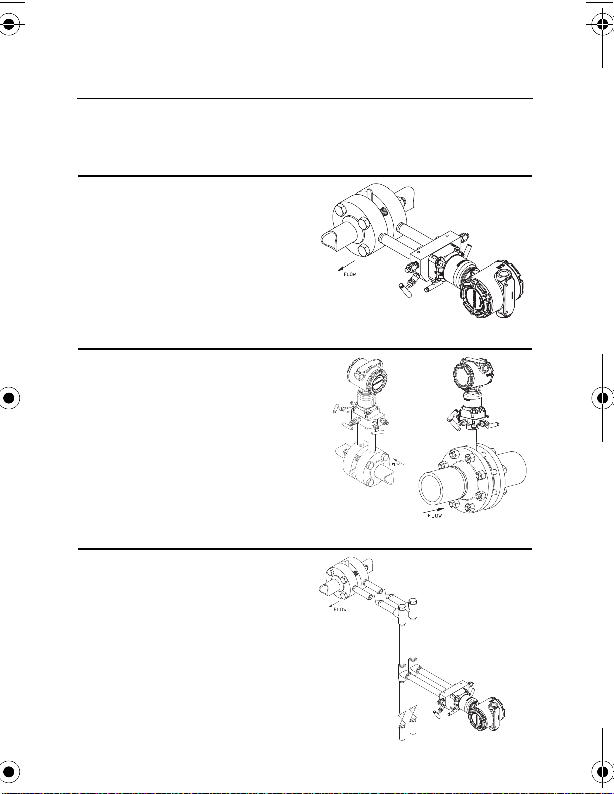
Liquid Flow Applications
1. Place taps to the side of the line.
2. Mount beside or below the taps.
3. Mount the transmitter so that the
drain/vent valves are oriented
upward.
Gas Flow Applications
1. Place taps in the top or side of
Rosemount 3051SMV
the line.
2. Mount beside or above the taps.
Steam Flow Applications
1. Place taps to the side of the line.
2. Mount beside or below the taps.
3. Fill impulse lines with water.
3
Quick Installation Guide
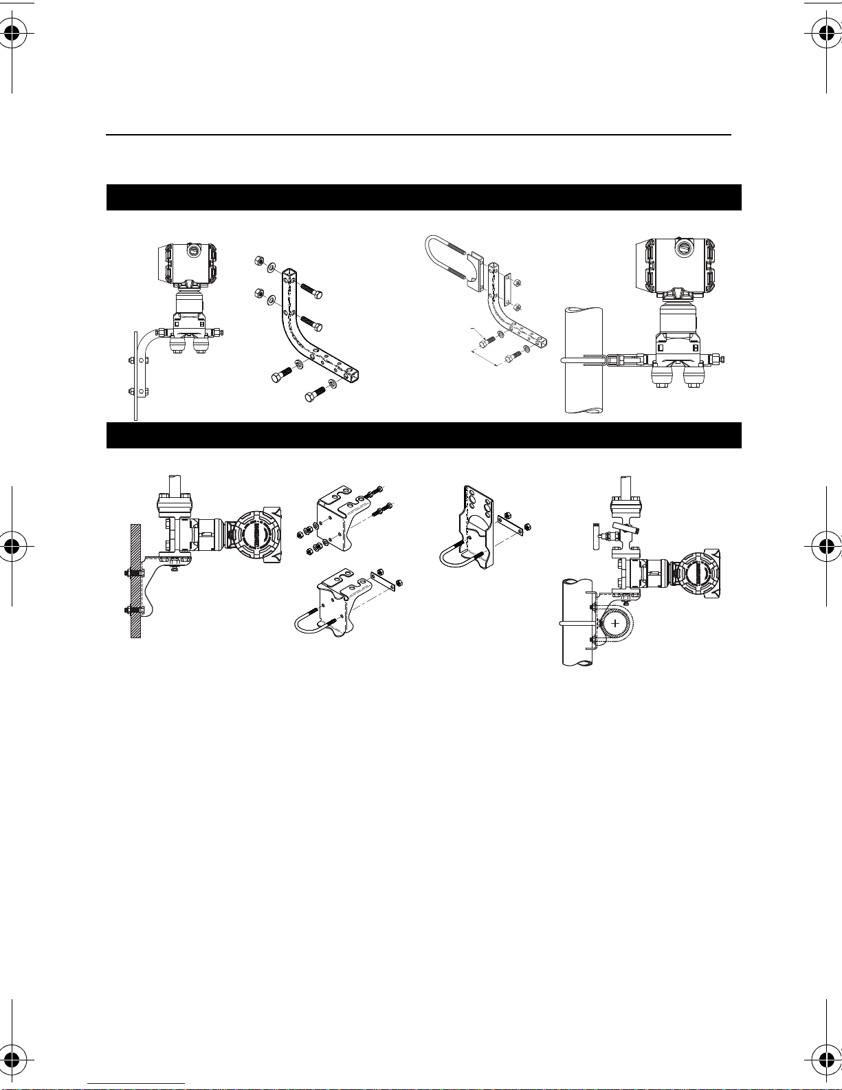
Pipe MountPanel Mount
Pipe Mount
Panel Mount
00825-0100-4803, Rev BA
Rosemount 3051SMV
Mounting Brackets
Coplanar™ Flange
Tr aditional Flange
April 2011
4
Quick Installation Guide
4 x 1.75-in.
(44 mm)
4 x 2.88-in.
(73 mm)
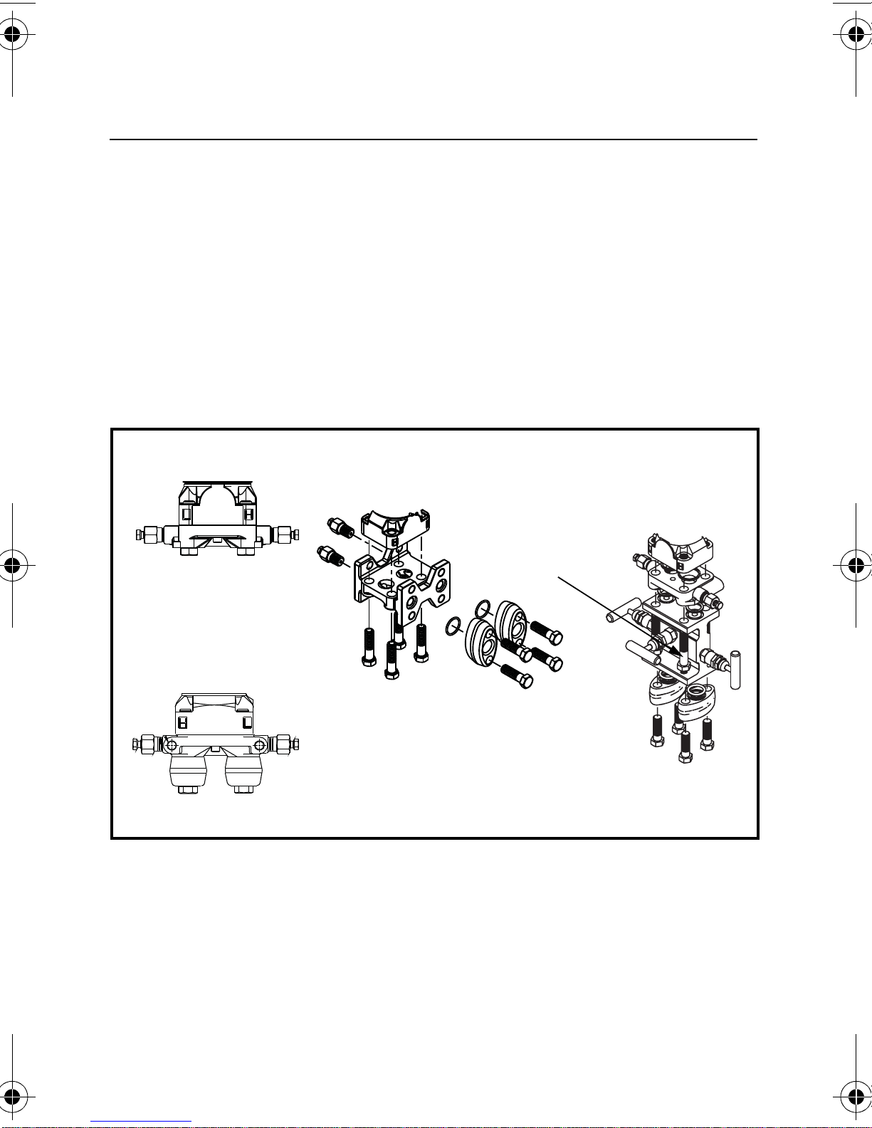
A. Transmitter with
Coplanar Flange
B. Transmitter with
Coplanar Flange and
Optional Flange
Adapters
C. Transmitter with
Traditional Flange and
Optional Flange
Adapters
D. Transmitter with
Coplanar Flange
and Optional
Manifold and Flange
Adapters
4 x 1.75-in.
(44 mm)
4 x 1.50-in.
(38 mm)
4 x 1.75-in.
(44 mm)
4 x 2.25-in.
(57 mm)
00825-0100-4803, Rev BA
April 2011
Rosemount 3051SMV
Bolting Considerations
If the transmitter installation requires assembly of a process flange,
manifold, or flange adaptors, follow these assembly guidelines to
ensure a tight seal for optimal performance characteristics of the
transmitter. Only use bolts supplied with the transmitter or sold by
Emerson Process Management as spare parts. Figure 1 illustrates
common transmitter assemblies with the bolt length required for
proper transmitter assembly.
Figure 1. Common Transmit ter Assemblies
5
Quick Installation Guide
Module Isolator Plate
Bolt
B7M
316
316
316
SW
316
STM
316
R
B8M
00825-0100-4803, Rev BA
Rosemount 3051SMV
April 2011
Bolts are typically carbon steel or stainless steel. Confirm the material
by viewing the markings on the head of the bolt and referencing
Figure 3. If bolt material is not shown in Figure 3, contact the local
Emerson Process Management representative for more information.
Use the following bolt installation procedure:
1. Carbon steel bolts do not require lubrication and the stainless steel
bolts are coated with a lubricant to ease installation. However, no
additional lubricant should be applied when installing either type of
bolt.
2. Finger-tighten the bolts.
3. Torque the bolts to the initial torque value using a crossing p attern.
See Figure 3 for initial torque value.
4. Torque the bolts to the final torque value using the same crossing
pattern. See Figure 3 for final torque value.
5. Verify that the flange bolts are protruding through the module
isolator plate before applying pressure.
Figure 2. Module Isolator Plate
Figure 3. Torque Values for the Flange and Flange Adap ter Bolts
Bolt Material Head Markings Initial T orque Final Torque
Carbon Steel
(CS)
Stainless Steel
(SST)
300 in.-lbs. 650 in.-lbs.
150 in.-lbs. 300 in.-lbs.
6
Quick Installation Guide
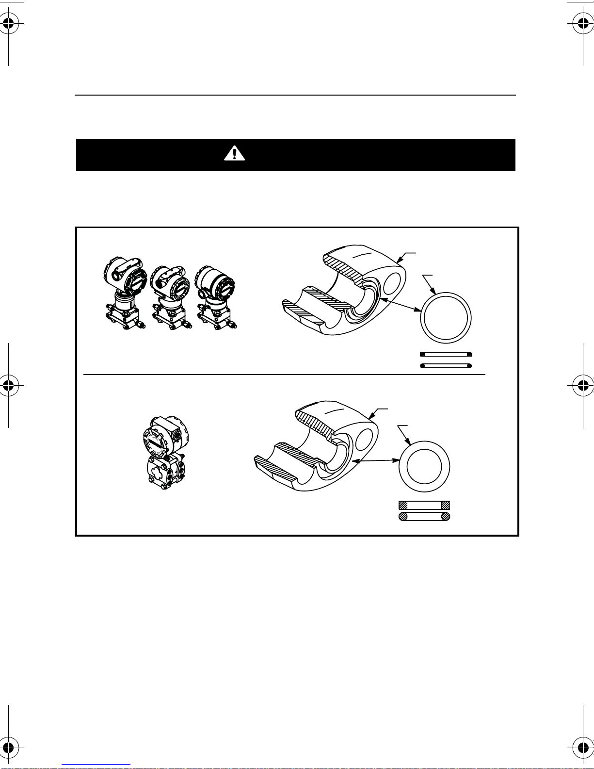
WARNING
Rosemount 3051S / 3051 / 2051 / 3095
Rosemount 1151
Flange Adapter
O-ring
Flange Adapter
O-ring
PTFE Based
Elastomer
PTFE
Elastomer
00825-0100-4803, Rev BA
April 2011
Rosemount 3051SMV
O-rings with Flange Adaptors
Failure to install proper flange adapter O-rings may cause process leaks, which
can result in death or serious injury. The two flange adapters are distinguished
by unique O-ring grooves. Only use the O-ring that is designed for its specific
flange adapter, as shown below.
Whenever the flange or adapters are removed, visually inspect the
o-rings. Replace them if there are any signs of damage, such as nicks
or cuts. If the o-rings are replaced, re-torque the flange bolts and
alignment screws after installation to compensate for seating of the
o-rings.
7

Quick Installation Guide
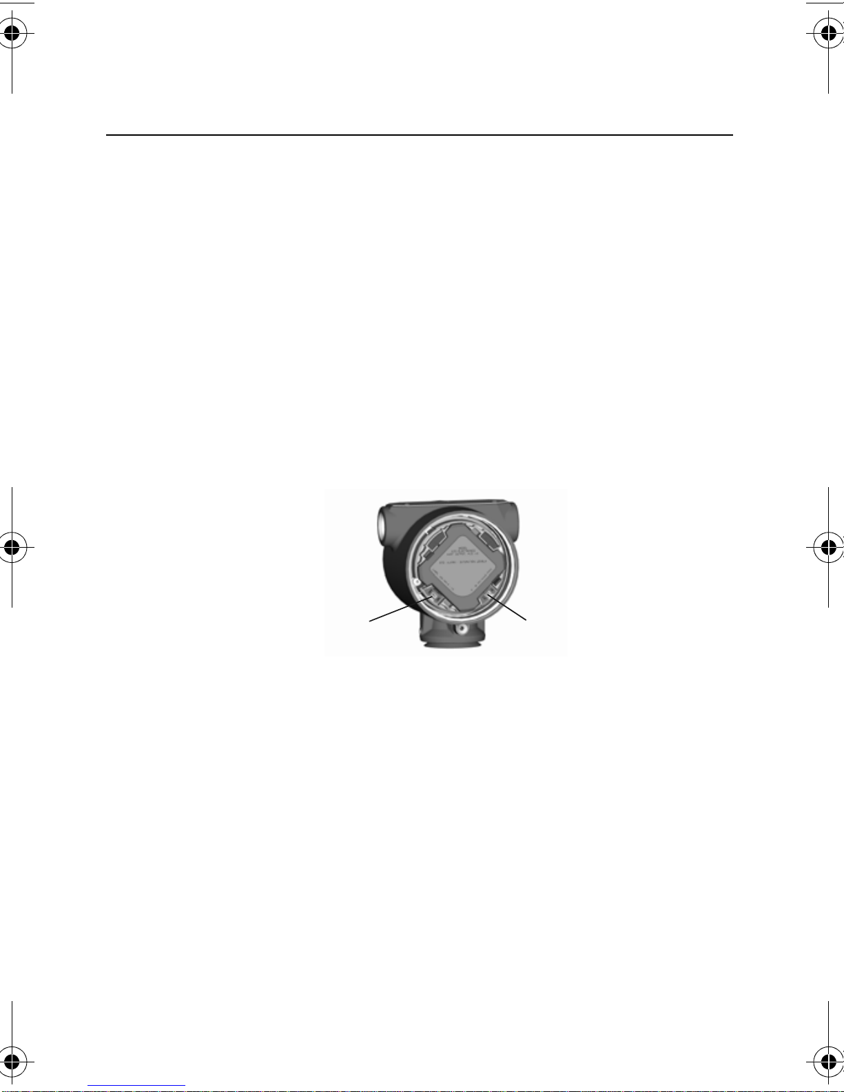
STEP 2: CONSIDER HOUSING ROTATION
Housing Rotation Set Screw
(3/32-in.)
Feature
Board
00825-0100-4803, Rev BA
Rosemount 3051SMV
To improve field access to wiring or to
better view the optional LCD display:
Figure 4. T ransmitter Housing
Set Screw
April 2011
1. Loosen the housing rotation set
screw.
2. Turn the housing up to 180° left or
right of its original (as shipped)
position.
3. Retighten the housing rotation set
screw.
NOTE
Do not rotate the housing more than 180° wit hout first performing a
disassembly procedure (see Section 4 of the 3051S MultiVariable transmitter
reference manual (00809-0100-4803) for more information). Over-rotation
may sever the electrical connection between the sensor module and the
feature board electronics.
8
Quick Installation Guide
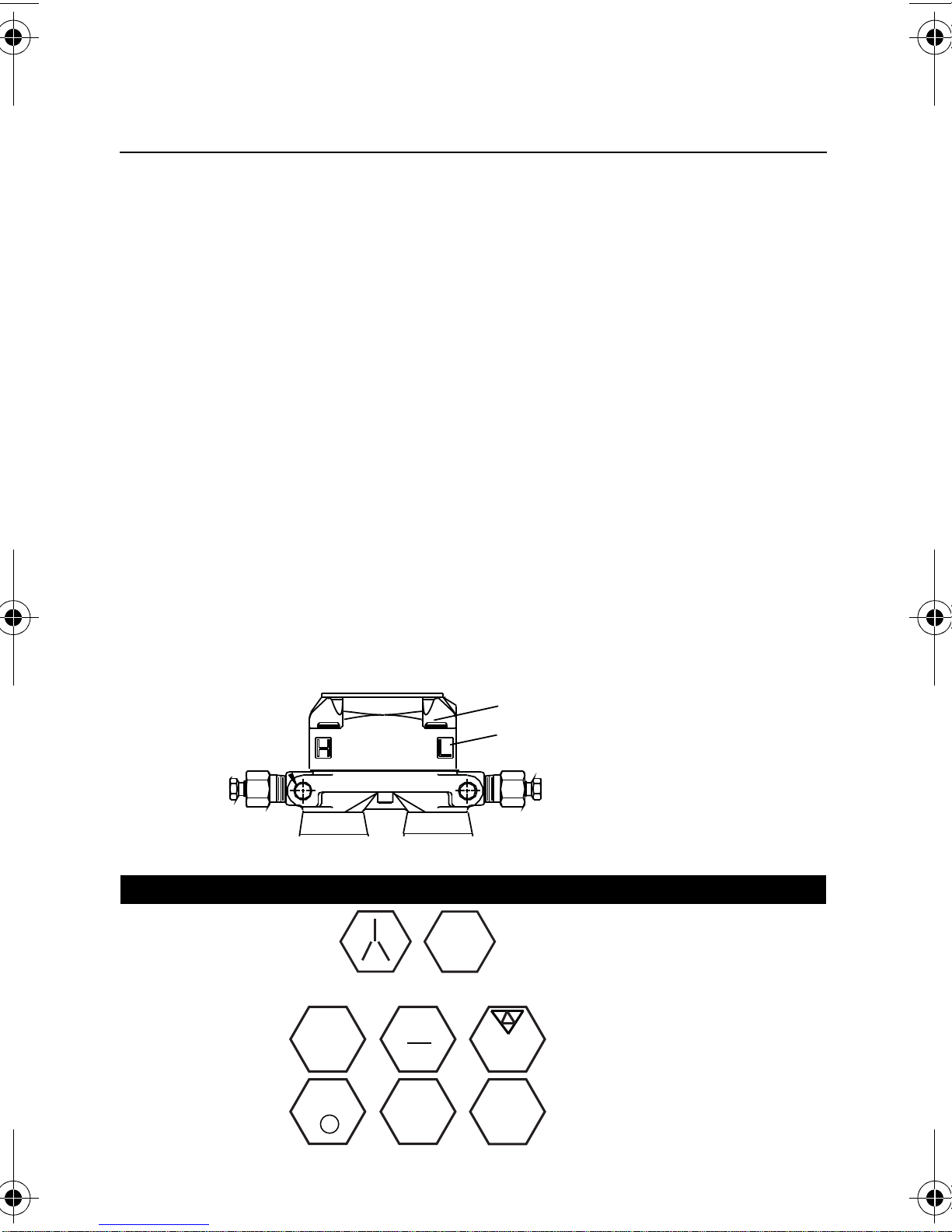
STEP 3: SET SWITCHES
Alarm
Security
00825-0100-4803, Rev BA
April 2011
The transmitter’s default configuration sets the alarm condition to high
(HI) and the security to off.
1. If the transmitter is installed, secure the loop and remove power.
2. Remove the housing cover opposite the field terminals side. Do not
remove the housing cover in explosive environments.
3. Slide the security and alarm switches into the preferred position by
using a small screwdriver.
4. Reinstall the housing cover so that metal contacts metal to meet
explosion-proof requirements.
Figure 5. Transmitter Switch Configuration
Rosemount 3051SMV
9
Quick Installation Guide
STEP 4: CONNECT WIRING AND POWER UP
IMPORTANT NOTICE
00825-0100-4803, Rev BA
Rosemount 3051SMV
NOTE
Do not connect the power across the test terminals. Power could damage the
test diode in the test connection. Twisted pa irs yield best result s. Use 24 A WG to
14 AWG wire and do not exceed 5,000 feet (1500 meters).
Use the following steps to wire the transmitter:
1. Remove the cover on the field terminals side of the housing.
2. Connect the positive lead to the “PWR/COMM +” terminal, and the
negative lead to the “PWR/COMM –” terminal.
3. If the optional process temperature input is not installed, plug and
seal the unused conduit connection. If the optional process
temperature input is being utilized, see “Install Optional Process
Temperature Input (Pt 100 RTD Sensor)” on page 13 for more
April 2011
information.
When the enclosed pipe plug is utilized in the conduit opening, it must be
installed with a minimum engagement of five threads in order to comply with
explosion-proof requirements. Refer to the 3051S MultiVariable transmitter
reference manual (document number 00809-0100-4803) for more information.
4. If applicable, install wiring with a drip loop. Arrange the drip loop
so the bottom is lower than the conduit connections and the
transmitter housing.
5. Reinstall the housing cover and tighten so that metal contacts
metal to meet explosion-proof requirements.
10
Quick Installation Guide
RL 250
Power
Supply
Power
Supply
RL 250
00825-0100-4803, Rev BA
April 2011
Rosemount 3051SMV
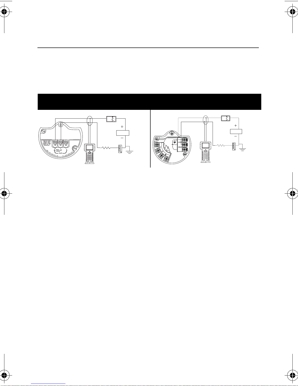
Figure 6 shows the wiring connections necessary to power a 3051S
MultiV ariable transmitter and enable communications with a hand-held
Field Communicator.
Figure 6. Transmitter Wiring
3051SMV without Optional Process
Temper at u r e C o nn e c t io n
3051SMV with Optional Process
Temperature Connection
NOTE
Installation of the tran sient protectio n terminal block does no t provide transient
protection unless the 3051S MultiVariable transmitter housing is properly
grounded.
Conduit Electrical Connector Wiring (Option GE or GM)
For 3051S MultiV ariable transmitters with conduit electrical connectors
GE or GM, refer to the cordset manufacturer’s installation instructions
for wiring details. For FM Intrinsically Safe, Division 2 hazardous
locations, install in accordance with Rosemount drawing 03151-1009
to maintain outdoor rating (NEMA 4X and IP66.) See Appendix B of
the 3051S MultiVariable transmitter reference manual
(00809-0100-4803).
11

Quick Installation Guide
Voltage (Vdc)
Load (Ohms)
Operating
Region
1322
1000
500
0
12.0 20 30
42.4
00825-0100-4803, Rev BA
Rosemount 3051SMV
April 2011
Power Supply
The dc power supply should provide power with less than two percent
ripple. The total resistance load is the sum of the resistance of the
signal leads and the load resistance of the controller, indicator , intrinsic
safety barriers, and related components.
Figure 7. Load Limitation
3051S MultiVariable Transmitter
Maximum Loop Resistance = 43.5 x (Power Supply Voltage – 12.0)
HART communication requires a minimum
12
loop resistance of 250.
Quick Installation Guide
RTD Cable Assembly
Wires
Red
White
Pt 100
RTD
Sensor
Ground Lug
00825-0100-4803, Rev BA
April 2011
Rosemount 3051SMV
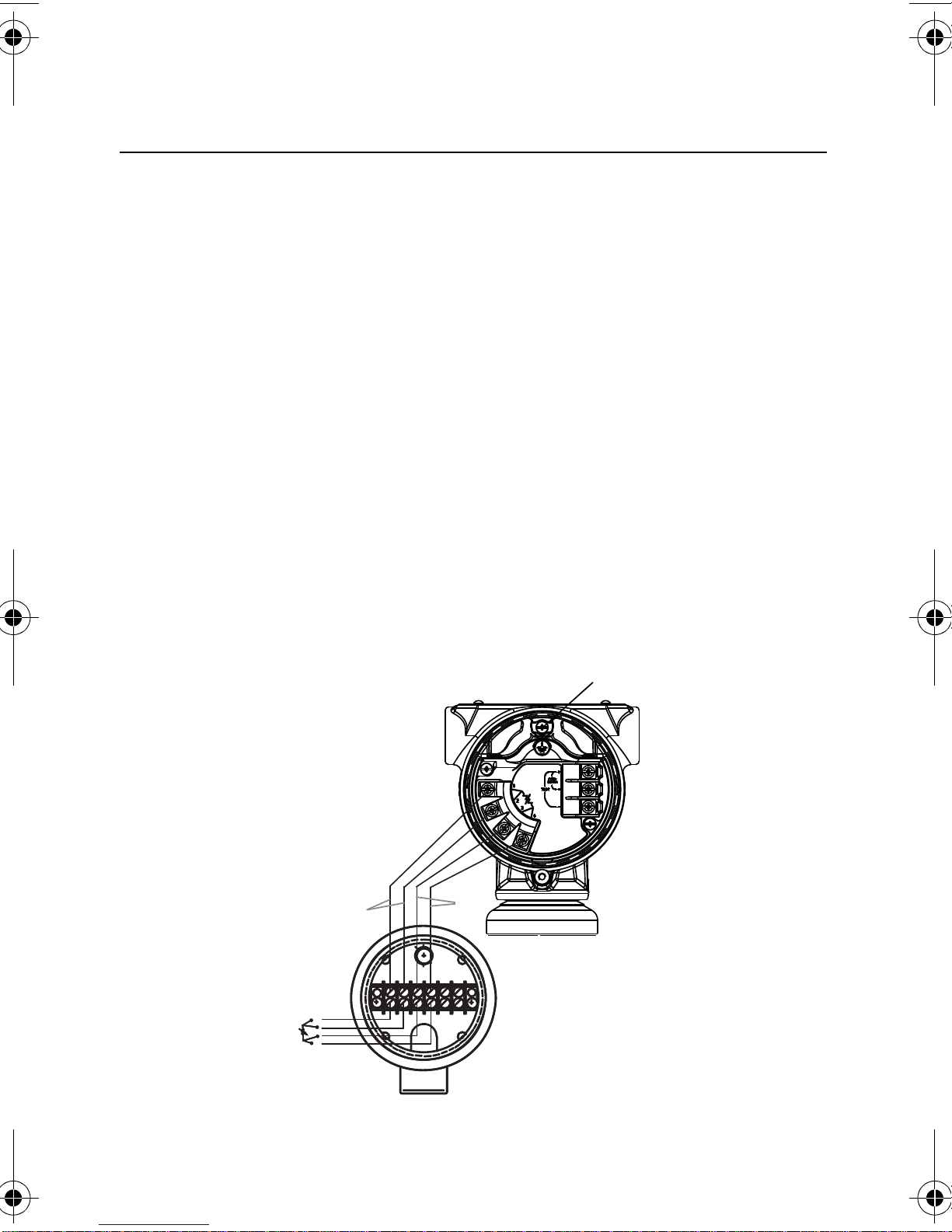
Install Optional Process Temperature Input
(Pt 100 RTD Sensor)
NOTE
To meet ATEX/IECEx Flameproof certification, only ATEX/IECEx Flameproof
Cables (Temperature Input Code C30, C32, C33, or C34) may be used.
1. Mount the Pt 100 RTD Sensor in the appropriate location.
NOTE
Use shielded four-wire cable for the process temperature connection.
2. Connect the RTD cable to the 3051S MultiVariable transmitter by
inserting the cable wires through the unused housing conduit and
connect to the four screws on the transmitter terminal block. An
appropriate cable gland should be used to seal the conduit opening
around the cable.
3. Connect the RTD cable shield wire to the ground lug in the
housing.
Figure 8. 3051S MultiVariable Transmitter RTD Wiring Connection
13

Quick Installation Guide
STEP 5: FLOW CONFIGURATION
00825-0100-4803, Rev BA
Rosemount 3051SMV
April 2011
Engineering Assistant 6.1 or Later
The 3051SMV Engineering Assistant 6.1 or later is PC-based software
that performs configuration, maintenance, diagnostic functions, and
serves as the primary communication interface to the 3051S
MultiVariable transmitter with the Fully Compensated Mass and
Energy Flow Feature Board.
The 3051SMV Engineering Assistant software is required to complete
the flow configuration.
Installation and Initial Setup
The following are the minimum system requirements to install the
3051SMV Engineering Assistant software:
• Pentium-grade Processor: 500 MHz or faster
• Operating System: Windows 2000(32-bit), Windows XP
Professional (32-bit), or Windows 7 (32-bit)
• 256 MB RAM
• 100 MB free hard disk space
• RS232 serial port or USB port (for use with HART modem)
• CD-ROM
14
 Loading...