

Page 1

Rosemount™ 3051S MultiVariable
Transmitter
Reference Manual
00809-0100-4803, Rev GB
October 2018
™
Page 2

Safety messages
NOTICE
Read this manual before working with the product. For personal and system safety, and for optimum product performance make
sure you thoroughly understand the contents before installing, using, or maintaining this product.
For technical assistance, contacts are listed below:
Customer Central
Technical support, quoting, and order-related questions. United States - 1-800-999-9307
(7:00 am to 7:00 pm CST) Asia Pacific- 65 777 8211Europe/Middle East/Africa - 49 (8153) 9390
North American Response Center
Equipment service needs.
1-800-654-7768 (24 hours—includes Canada)
Outside of these areas, contact your local Emerson™ representative.
CAUTION
The products described in this document are NOT designed for nuclear-qualified applications. Using non-nuclear qualified
products in applications that require nuclear-qualified hardware or products may cause inaccurate readings.For information on
Rosemount nuclear-qualified products, contact your local Emerson Sales Representative.
WARNING
Explosions could result in death or serious injury.
Installation of this transmitter in an explosive environment must be in accordance with the appropriate local, national, and
international standards, codes, and practices. Review the approvals section of this manual for any restrictions associated with a
safe
• — Before connecting a Field Communicator in an explosive atmosphere, ensure the instruments in the loop are installed in
accordance with intrinsically safe or non-incendive field wiring practices.
— In an explosion-proof/flameproof installation, do not remove the transmitter covers when power is applied to the unit.
Process leaks may cause harm or result in death.
• — Install and tighten process connectors before applying pressure.
— Do not attempt to loosen or remove flange bolts while the transmitter is in service.
Electrical shock can result in death or serious injury.
• Avoid contact with the leads and terminals. High voltage that may be present on leads can cause electrical shock.
2
Page 3

Warnings
WARNING
Explosions could result in death or serious injury.
Installation of this transmitter in an explosive environment must be in accordance with the appropriate local, national, and
international standards, codes, and practices. Please review the approvals section of the Rosemount 2051 Reference Manual for
any restrictions associated with a safe installation.
• Before connecting a HART® communicator in an explosive atmosphere, ensure the instruments in the loop are installed in
accordance with intrinsically safe or non-incendive field wiring practices.
• In an Explosion-Proof/Flameproof installation, do not remove the transmitter covers when power is applied to the unit.
Process leaks may cause harm or result in death.
• Install and tighten process connectors before applying pressure.
Electrical shock can result in death or serious injury.
• Avoid contact with the leads and terminals. High voltage that may be present on leads can cause electrical shock.
WARNING
Electrical shock can result in death or serious injury.
• Avoid contact with the leads and terminals.
Process leaks could result in death or serious injury.
• Install and tighten all four flange bolts before applying pressure.
• Do not attempt to loosen or remove flange bolts while the transmitter is in service.
Replacement equipment or spare parts not approved by Emerson Process Management for use as spare parts could reduce the
pressure retaining capabilities of the transmitter and may render the instrument dangerous.
• Use only bolts supplied or sold by Emerson Process Management as spare parts.
• Refer to page 208 for a complete list of spare parts.
Improper assembly of manifolds to traditional flange can damage sensor module.
• For safe assembly of manifold to traditional flange, bolts must break back plane of flange web (i.e., bolt hole) but must not
contact sensor module housing.
3
Page 4

4
Page 5

Reference Manual Contents
00809-0100-4803 October 2018
Contents
Chapter 1 Introduction ................................................................................................................. 7
1.1 Using this manual ............................................................................................................................ 7
1.2 Product recycling/disposal .............................................................................................................. 8
Chapter 2 Configuration ............................................................................................................... 9
2.1 Overview ......................................................................................................................................... 9
2.2 Unresolved topicref ......................................................................................................................... 9
2.3 Engineering Assistant installation .................................................................................................. 10
2.4 Flow configuration ........................................................................................................................ 12
2.5 Basic device configuration ............................................................................................................. 31
2.6 Detailed device configuration ....................................................................................................... 34
2.7 Variable configuration ................................................................................................................... 43
2.8 Menu trees and Field Communicator Fast Keys ............................................................................. 62
Chapter 3 Installation ................................................................................................................. 71
3.1 Overview ....................................................................................................................................... 71
3.2 Safety messages ........................................................................................................................... 71
3.3 Installation considerations ............................................................................................................ 72
3.4 Installation procedures ................................................................................................................. 73
3.5 Rosemount 305 and 304 Manifolds ............................................................................................... 91
Chapter 4 Operation and Maintenance ...................................................................................... 107
4.1 Overview ..................................................................................................................................... 107
4.2 Safety messages ......................................................................................................................... 107
4.3 Transmitter calibration ............................................................................................................... 108
4.4 Transmitter functional tests ........................................................................................................ 117
4.5 Process variables ......................................................................................................................... 118
4.6 Field upgrades and replacements ................................................................................................ 120
Chapter 5 Troubleshooting ....................................................................................................... 129
5.1 Overview ..................................................................................................................................... 129
5.2 Device diagnostics ...................................................................................................................... 129
5.3 Measurement quality and limit status ......................................................................................... 135
5.4 Engineering Assistant communication troubleshooting .............................................................. 137
5.5 Measurement troubleshooting ................................................................................................... 137
5.6 Service support ........................................................................................................................... 141
Chapter 6 Safety Instrumented Systems Requirements ............................................................. 143
6.1 Safety Instrumented Systems (SIS) Certification .......................................................................... 143
6.2 Rosemount 3051SMV safety certified identification .................................................................... 143
6.3 Installation in SIS applications ..................................................................................................... 143
Emerson.com/Rosemount 5
Page 6

Contents Reference Manual
October 2018 00809-0100-4803
6.4 Configuring in SIS applications .................................................................................................... 144
6.5 Rosemount 3051SMV SIS operation and maintenance ................................................................ 145
6.6 Inspection ................................................................................................................................... 147
Appendix A Appendix A ............................................................................................................... 149
A.1 Product Certifications ................................................................................................................. 149
A.2 Ordering Information, Specifications, and Dimensional Drawings ............................................... 149
6 Rosemount 3051S Multivariable Transmitter
Page 7

Reference Manual Introduction
00809-0100-4803 October 2018
1 Introduction
1.1 Using this manual
The sections in this manual provide information on installing, operating, and maintaining
the Rosemount™ 3051S MultiVariable™ Transmitter (Rosemount 3051SMV). The sections
are organized as follows:
• Configuration provides instruction on commissioning and operating Rosemount
3051SMV. Information on software functions, configuration parameters, and online
variables is also included.
• Installation contains mechanical and electrical installation instructions.
• Operation and Maintenance contains operation and maintenance techniques.
• Troubleshooting provides troubleshooting techniques for the most common operating
problems.
• Safety Instrumented Systems Requirements contains identification, commissioning,
maintenance, and operations information for the Rosemount 3051S MultiVariable
Safety Instrumented System (SIS) Safety Transmitter.
• Specifications and Reference Data supplies reference and specification data, as well as
ordering information.
• Contains intrinsic safety approval information, European ATEX directive information,
and approval drawings.
1.1.1
Models covered
The following Rosemount 3051SMV Transmitters are covered in this manual:
Table 1-1: Rosemount 3051SMV Measurement with Fully Compensated Mass and
Energy Flow Output
Measurement type Multivariable type - M
1 Differential pressure, static pressure, temperature
2 Differential pressure and static pressure
3 Differential pressure and temperature
4 Differential pressure
Table 1-2: Rosemount 3051SMV Measurement with Direct Process Variable Output
Measurement type Multivariable type - P
1 Differential pressure, static pressure, temperature
2 Differential pressure and static pressure
3 Differential pressure and temperature
5 Coplanar static pressure and temperature
6 In-line static pressure and temperature
Emerson.com/Rosemount 7
Page 8

Introduction Reference Manual
October 2018 00809-0100-4803
1.2 Product recycling/disposal
Recycling of equipment and packaging should be taken into consideration and disposed of
in accordance with local and national legislation/regulations.
8 Rosemount 3051S Multivariable Transmitter
Page 9

Reference Manual Configuration
00809-0100-4803 October 2018
2 Configuration
2.1 Overview
This section contains information for configuring the flow and device configuration for the
Rosemount™ 3051S MultiVariable™ Transmitter (Rosemount 3051SMV). Engineering
Assistant installation and Flow configuration instructions apply to Engineering Assistant
version 6.3 or later. Basic device configuration, Detailed device configuration , and
Variable configuration are shown for AMS Device Manager version 9.0 or later, but also
include Fast Key sequences for Field Communicator version 2.0 or later. Engineering
Assistant and AMS Device Manager screens are similar and follow the same instructions for
use and navigation. For convenience, Field Communicator Fast Key sequences are labeled
“Fast Keys” for each software function below the appropriate headings. The functionality
of each host as show in Table 2-1:
Note
Coplanar transmitter configurations measuring gage pressure and process temperature
(measurement 5) will report as the pressure as differential pressure. This will be reflected
on the LCD display, nameplate, digital interfaces, and other user interfaces.
Table 2-1: Host Functionality
• Available — Not available
Multivariable
type
Fully
compensated
mass and energy
flow (M)
Direct process
variable output
(P)
Functionality Rosemount 3051SMV
Flow Configuration • • —
Device Configuration • • •
Test Calculation • • •
Calibration • • •
Diagnostics • • •
Device Configuration — • •
Calibration — • •
Diagnostics — • •
2.2 Unresolved topicref
Unresolved topicref placeholder.
This is a placeholder for unresolved topicref links.
Engineering Assistant
AMS Device
Manager
Field Communicator
Emerson.com/Rosemount 9
Page 10

Configuration Reference Manual
October 2018 00809-0100-4803
2.3 Engineering Assistant installation
2.3.1 Engineering Assistant version 6.3 or later
The Rosemount 3051SMV Engineering Assistant 6.3 or later is PC-based software that
performs configuration, maintenance, diagnostic functions, and serves as the primary
communication interface to the Rosemount 3051SMV with the fully compensated mass
and energy flow feature board.
The Rosemount 3051SMV Engineering Assistant software is required to complete the flow
configuration.
2.3.2 Installation and initial setup
The following are the minimum system requirements to install the Rosemount 3051SMV
Engineering Assistant software:
• Pentium-grade Processor: 500 MHz or faster
• Operating system: Windows™ Professional 7, 8.1, 10
— 32-bit
— 64-bit
• 256 ΜΒ RΑΜ
• 100 ΜΒ free hard disk space
• RS232 serial port or USB port (for use with HART® modem)
• CD-ROM
Installing the Rosemount 3051SMV Engineering Assistant version 6.3 or later
About this task
Engineering Assistant is available with or without the HART modem and connecting
cables. The complete Engineering Assistant package contains the software CD and one
HART modem with cables for connecting the computer to the Rosemount 3051SMV (See
Ordering information.)
Procedure
1. Uninstall any existing versions of Engineering Assistant 6 currently installed on the
PC.
2. Insert the new Engineering Assistant disk into the CD-ROM.
3. Windows should detect the presence of a CD and start the installation program.
Follow the on-screen prompts to finish the installation. If Windows does not detect
the CD, use Windows Explorer or My Computer to view the contents of the CDROM, and then double select the SETUP.EXE program.
4. A series of screens (Installation Wizard) will appear and assist in the installation
process. Follow the on-screen prompts. It is recommended the default installation
settings are used.
10 Rosemount 3051S Multivariable Transmitter
Page 11
A
RL ≥ 250Ω
B
A
RL ≥ 250Ω
B
Reference Manual Configuration
00809-0100-4803 October 2018
Example
Note
Engineering Assistant version 6.3 or later requires the use of Microsoft® .NET Framework
version 4.0 or later. If .NET version 4.0 is not currently installed, the software will be
automatically installed during the Engineering Assistant installation. Microsoft .NET
version 4.0 requires an additional 200 MB of disk space.
Connecting to a PC
About this task
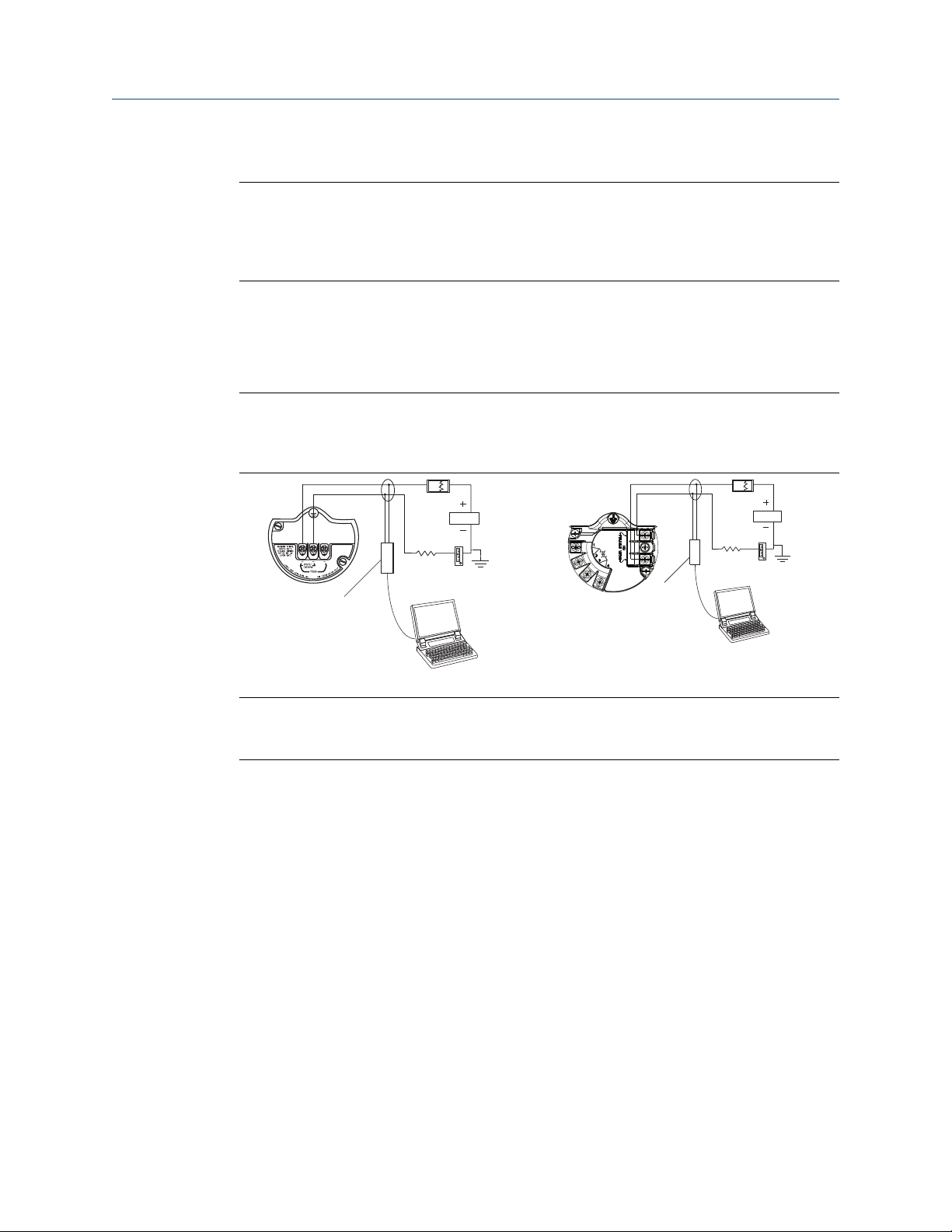
Figure 2-1 shows how to connect a computer to a Rosemount 3051SMV.
Figure 2-1: Connecting a PC to the Rosemount 3051SMV
Rosemount 3051SMV without optional
process temperature connection
Rosemount 3051SMV with optional process
temperature connection
A. Power supply
B. HART modem
Procedure
1. Remove the cover from the field terminals side of the housing.
2. Power the device as outlined in Connect wiring and power up.
3. Connect the HART modem cable to the PC.
4. On the side marked “Field Terminals,” connect the modem mini-grabbers to the
two terminals marked “PWR/COMM.”
5. Launch the Rosemount 3051SMV Engineering Assistant. For more information on
launching Engineering Assistant, see Launching Engineering Assistant.
6. Once the configuration is complete, replace cover and tighten until metal contacts
metal to meet flameproof/explosion-proof requirements. See Cover installation for
more information.
Emerson.com/Rosemount 11
Page 12
Start
Process fluid
selection
Natural gas Custom liquid
Custom gas
Custom gas or
custom liquid
fluid properties
Natural gas
composition
Fluid properties
(optional)
Database liquid
Database gas or
steam
Primary
element
selection
Save/Send
flow
configuration
Ideal gas
Configuration Reference Manual
October 2018 00809-0100-4803
2.4 Flow configuration
2.4.1 Rosemount 3051SMV Engineering Assistant 6.3 or later
The Rosemount 3051SMV Engineering Assistant is designed to guide the user through the
setup of the flow configuration of a Rosemount 3051SMV. The flow configuration screens
allow the user to specify the fluid, operating conditions, and information about the
primary element including the inside pipe diameter. This information will be used by the
Rosemount 3051SMV Engineering Assistant to create the flow configuration parameters
that can be sent to the transmitter or saved for future use.
NOTICE
To ensure correct operation, download the most current version of the Engineering
Assistant software at Emerson.com/en-us/catalog/rosemount-engineering-assistant-6.
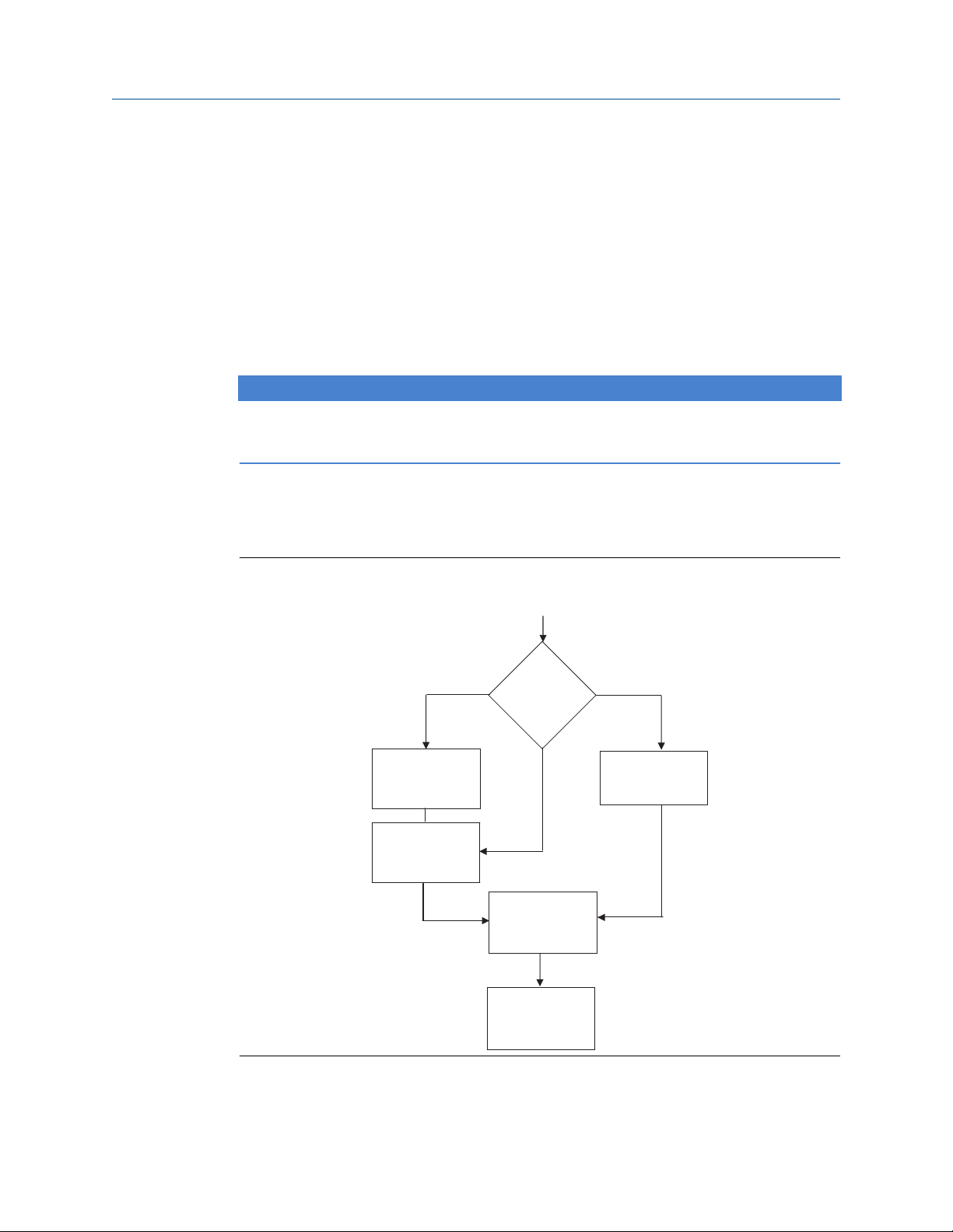
Figure 2-2 shows the path in which the Rosemount 3051SMV Engineering Assistant will
guide the user through a flow configuration. If a natural gas, custom liquid, or custom gas
option is chosen, an extra screen will be provided to specify the gas composition or fluid
properties.
Figure 2-2: Flow Configuration Flowchart
12 Rosemount 3051S Multivariable Transmitter
Page 13

Reference Manual Configuration
00809-0100-4803 October 2018
Online and offline mode
The Engineering Assistant software can be used in two modes: online and offline. In online
mode, the user can receive the configuration from the transmitter, edit the configuration,
send the changed configuration to the transmitter, or save the configuration to a file. In
offline mode, the user may create a new flow configuration and save the configuration to a
file or open and modify an existing file.
Emerson.com/Rosemount 13
Page 14
A
B C D E
G
H
F
Configuration Reference Manual
October 2018 00809-0100-4803
2.4.2 Basic navigation overview
Figure 2-3: Engineering Assistant Basic Navigation Overview
The Engineering Assistant software can be navigated in a variety of ways. The numbers
below correspond to the numbers shown in Figure 2-3.
A. The navigation tabs contain the flow configuration information. In offline mode, each
tab will not become active until the required fields on the previous tab are completed. In
online mode, these tabs will be functional unless a change on a preceding tab is made.
B. The Reset button will return each field within all of the flow configuration tabs (Fluid
Selection, Fluid Properties, and Primary Element Selection) to the values initially
displayed at the start of the configuration.
A. If editing a previously saved flow configuration, the values will return to those
that were last saved.
B. If starting a new flow configuration, all entered values will be erased.
C. The Back button is used to step backward through the flow configuration tabs.
D. The Next button is used to step forward through the flow configuration tabs. The Next
button will not become active until all required fields on the current page are completed.
E. The Help button may be selected at any time to get a detailed explanation of the
information required on the current configuration tab.
F. Any configuration information that needs to be entered or reviewed will appear in this
portion of the screen.
G. These menus navigate to the Configure Flow, Basic Setup, Device, Variables, Calibration,
and Save/Send tabs.
H. These buttons navigate to Config/Setup, Device Diagnostics, or Process Variables
sections.
14 Rosemount 3051S Multivariable Transmitter
Page 15
Reference Manual Configuration
00809-0100-4803 October 2018
2.4.3 Launching Engineering Assistant
About this task
Flow configuration for the Rosemount 3051SMV is achieved by launching the Engineering
Assistant Software from the START menu. The following steps show how to open the
Engineering Assistant Software, and connect to a device:
Procedure
1. Select the Start menu > All Programs > Engineering Assistant. Engineering
Assistant will open to screen as shown in Figure 2-4.
2. If working offline, select the Offline button located on the bottom of the screen as
shown in Figure 2-4.
Example
OR
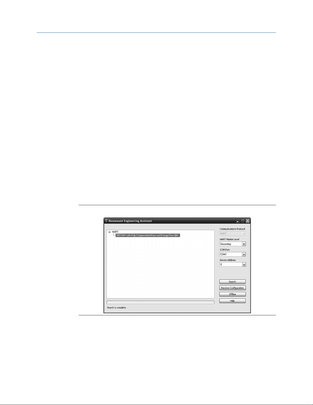
If working online, select the Search button located on the lower right corner of the screen
as shown in Figure 2-4. Engineering Assistant will begin to search for online devices. When
the search is completed, select the device to communicate with and select Receive
Configuration button.
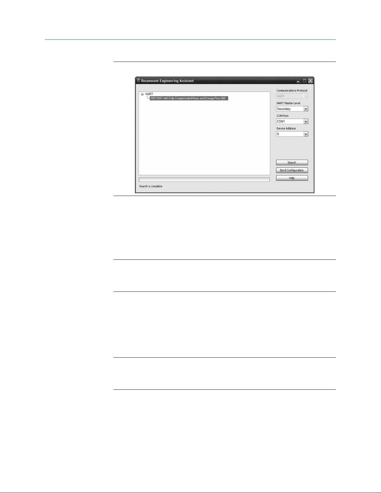
2.4.4
The HART Master Level can be set to either primary or secondary. Secondary is the default
and should be used when the transmitter is on the same segment as another HART
communication device. The COM Port and device address may also be edited as needed.
Figure 2-4: Engineering Assistant Device Connection Screen
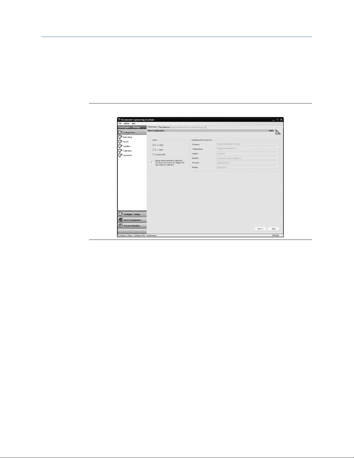
Preferences
The Preferences tab, shown in Figure 2-5, allows the user to select the preferred
engineering units to display and specify flow configuration information.
Emerson.com/Rosemount 15
Page 16
Configuration Reference Manual
October 2018 00809-0100-4803
• Select the preferred engineering units. If units are needed other than the default U.S.
or S.I. units, use the Custom Units setting. If Custom Units are selected, configure the
Individual Parameters using the drop-down menus.
• Unit preferences selected will be retained for future Engineering Assistant sessions.
Check the box to prevent the Preferences tab from being automatically shown in future
sessions. The Preferences are always available by select the Preferences tab.
Figure 2-5: Preferences Tab
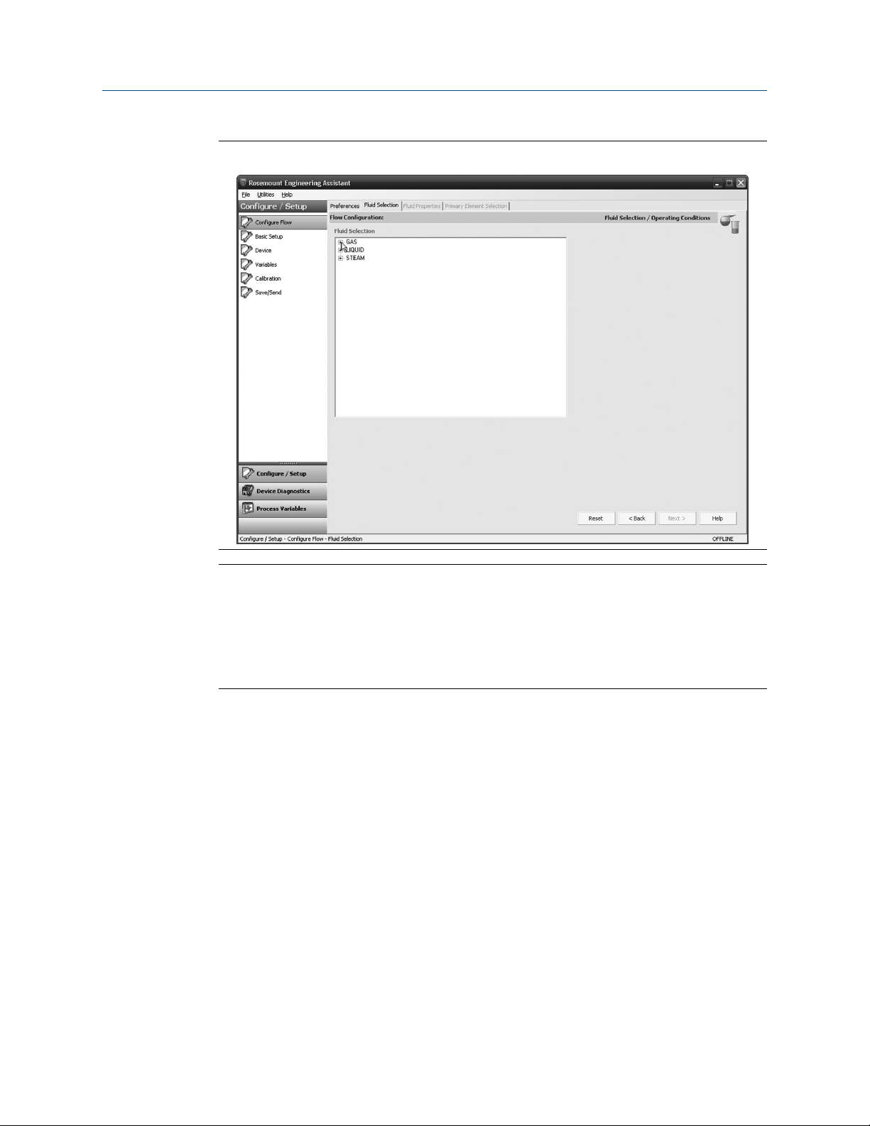
2.4.5 Fluid selection for database liquid/gas
About this task
The Fluid Selection tab (see Figure 2-6) allows the user to select the process fluid.
16 Rosemount 3051S Multivariable Transmitter
Page 17
Reference Manual Configuration
00809-0100-4803 October 2018
Figure 2-6: Fluid Selection Tab
Note
The following example will show a flow configuration for an application with database gas
air as the process fluid and a Rosemount 405C Conditioning Orifice Plate as the primary
element. The procedure to configure an application with other fluids and other primary
elements will be similar to this example. Natural gases, custom liquids, and custom gases
require additional steps during the configuration. See Other fluid configurations for more
information.
Procedure
1. Engineering Assistant may open to the Preferences tab. Using the tabs at the top of
the screen, navigate to the Fluid Selection tab.
2. Expand the Gas category (select the + icon).
3. Expand the Database Gas category.
4. Select the appropriate fluid (Air for this example) from the list of database fluids.
Emerson.com/Rosemount 17
Page 18
Configuration Reference Manual
October 2018 00809-0100-4803
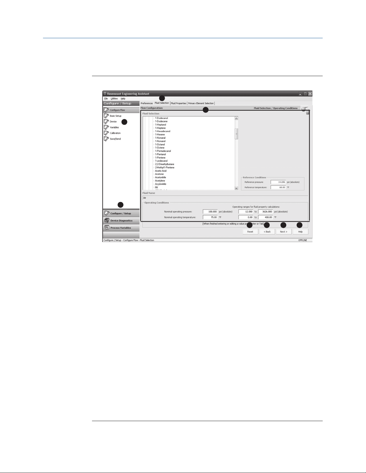
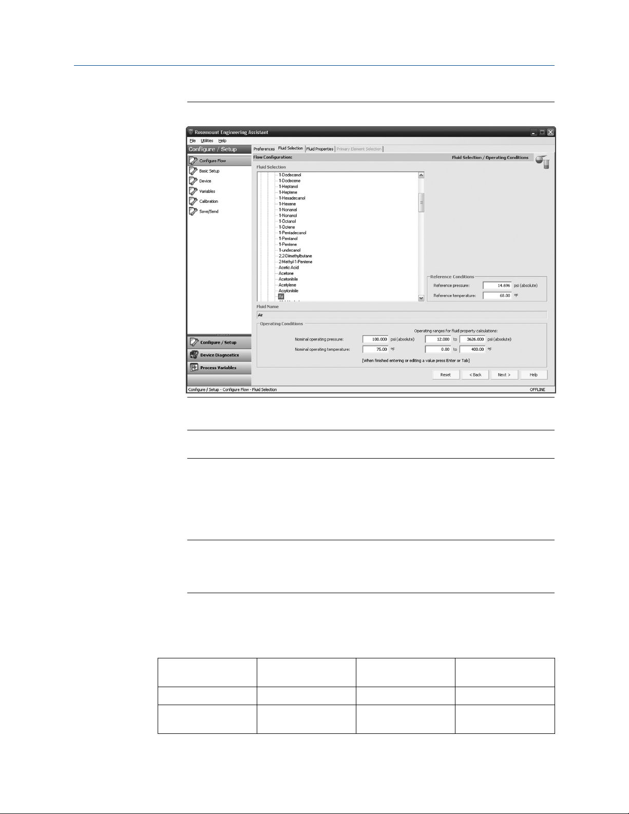
Figure 2-7: Fluid Selection Tab - Database Gas Air
5. Enter the Nominal Operating Pressure, select the Enter or Tab key.
Note
The nominal operating pressure must be entered in absolute pressure units.
6. Enter the Nominal Operating Temperature, select the Enter or Tab key. Engineering
Assistant will automatically fill in suggested operating ranges, as shown in . These
values may be edited as needed by the user.
7. Verify the Reference Conditions are correct for the application. These values may be
edited as needed.
Note
Reference pressure and temperature values are used by Engineering Assistant to
convert the flow rate from mass units to mass units expressed as standard or
normal volumetric units.
8. Select Next > to proceed to the Fluid Properties tab.
Example
Table 2-2: Liquids and Gases Database
1,1,2,2–
Tetrafluoroethane
1,1,2–Trichloroethane Air Formic Acid Nonanal
1,2,4–
Trichlorobenzene
Acrylonitrile Formaldehyde Nitrous Oxide
Allyl Alcohol Furan n–Butane
18 Rosemount 3051S Multivariable Transmitter
Page 19

Reference Manual Configuration
00809-0100-4803 October 2018
Table 2-2: Liquids and Gases Database (continued)
1,2–Butadiene Ammonia Helium–4 n–Butanol
1,2–Propylene Glycol Aniline Hydrazine n–Butyraldehyde
1,3–Propylene Glycol Argon Hydrogen n–Butyronitrile
1,3,5–
Trichlorobenzene
1,3–Butadiene Benzaldehyde Hydrogen Cyanide n–Dodecane
1,4–Dioxane Benzyl Alcohol Hydrogen Peroxide n–Heptadecane
1,4–Hexadiene Biphenyl Hydrogen Sulfide n-Heptane
1–Butene Bromine Isobutane n–Hexane
1–Decanol Carbon Dioxide Isobutylbenzene n-Nonane
1–Decene Carbon Monoxide Isohexane n–Octane
1–Dodecanol Carbon Tetrachloride Isoprene n–Pentane
1–Dodecene Chlorine Isopropanol Oxygen
1–Heptanol ChlorotrifluoroethyleneMelamine Pentafluoroethane
1–Heptene Chloroprene Methane Phenol
1–Hexadecanol Cycloheptane Methanol Propane
1–Hexene Cyclohexane Methyl Acrylate Propadiene
1–Octanol Cyclopentane Methyl Ethyl Ketone Pyrene
1–Octene Cyclopentene Methyl Vinyl Ether Propylene
1–Nonanol Cyclopropane m–
Benzene Hydrogen Chloride n–Decane
p-Nitroaniline
Chloronitrobenzene
1–Pentadecanol Decanal m–Dichlorobenzene Sorbitol
1–Pentanol Divinyl Ether Neon Styrene
1–Pentene Ethane Neopentane Sulfur Dioxide
1–Undecanol Ethanol Nitric Acid Toluene
2,2–Dimethylbutane Ethylamine Nitric Oxide Trichloroethylene
2–Methyl–1–Pentene Ethylbenzene Nitrobenzene Vinyl Acetate
Acetic Acid Ethylene Nitroethane Vinyl Chloride
Acetone Ethylene Glycol Nitrogen Vinyl Cyclohexane
Acetonitrile Ethylene Oxide Nitrogen Trifluoride Vinylacetylene
Acetylene Fluorene Nitromethane Water
Emerson.com/Rosemount 19
Page 20
Configuration Reference Manual
October 2018 00809-0100-4803
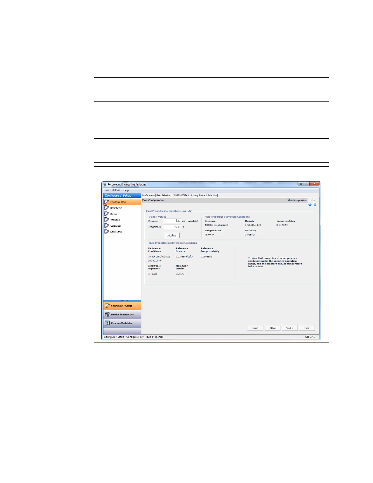
2.4.6 Fluid properties
Note
The Fluid Properties tab is an optional step and is not required to complete a flow
configuration.
The Fluid Properties tab for the database gas air is shown in Figure 2-8. The user may view
the properties of the chosen fluid. The fluid properties are initially shown at nominal
conditions. To view density, compressibility, and viscosity of the selected fluid at other
pressure and temperature values, enter a Pressure and Temperature and select Calculate.
Note
Changing the pressure and temperature values on the Fluid Properties tab does not affect
the flow configuration.
Figure 2-8: Fluid Properties Tab
2.4.7
20 Rosemount 3051S Multivariable Transmitter
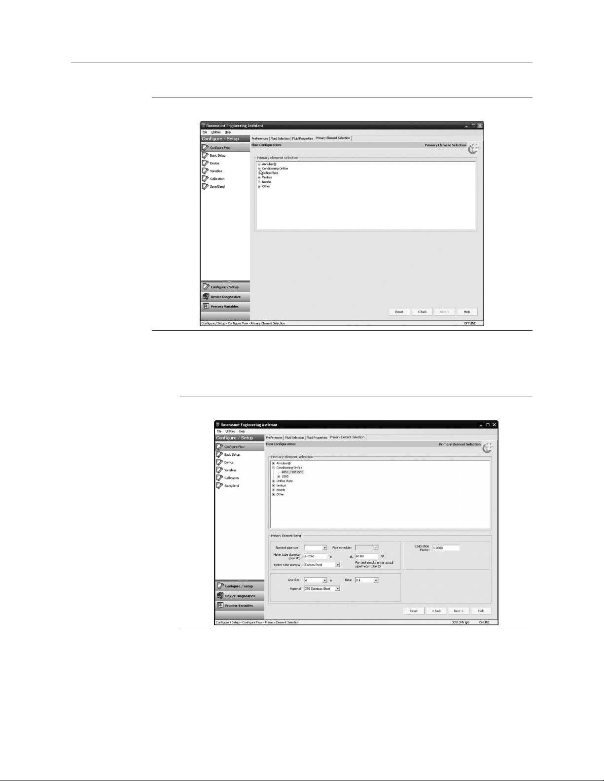
Primary element selection
About this task
The Primary Element Selection tab shown in Figure 2-9 allows the user to select the
primary element that will be used with the Rosemount 3051SMV. This database of primary
elements includes:
• Rosemount proprietary elements such as the Rosemount Annubar™ and the
conditioning orifice plate
• Standardized primary elements such as ASME, ISO, and AGA primary elements
• Other proprietary primary elements
Page 21
Reference Manual Configuration
00809-0100-4803 October 2018
Figure 2-9: Primary Element Selection Tab
Continuing with the example configuration:
Procedure
1. Expand the Conditioning Orifice category.
Figure 2-10: Primary Element Selection Tab - 405C/3051SFC
2. Select 405C/3051SFC.
3. Enter the Measured Meter Tube Diameter (pipe ID) at a Reference Temperature. If
the meter tube diameter cannot be measured, select a Nominal Pipe Size and Pipe
Schedule to input an estimated value for the meter tube diameter (U.S. units only).
4. If necessary, edit the Meter Tube Material.
Emerson.com/Rosemount 21
Page 22

Configuration Reference Manual
October 2018 00809-0100-4803
5. Enter the Line Size and select the Beta of the Conditioning Orifice Plate. The
required primary element sizing parameters will be different depending on what
primary element is selected.
6. If necessary, select a Primary Element Material from the drop-down menu.
7. A calibration factor may be entered if a calibrated primary element is being used.
Note
A Joule-Thomson Coefficient can be enabled to compensate for the difference in
process temperature between the orifice plate location and the process
temperature measurement point. The Joule-Thomson Coefficient is available with
ASME MFC-3M-2 (2004) or ISO 5167-2.2003 (E) orifice plates used with Database
Gases, Superheated Steam, or AGA DCM/ISO Molar Composition Natural Gas. For
more information on the Joule-Thomson Coefficient, reference the appropriate
orifice plate standard.
8. Select Next > to advance to the Save/Send Configuration tab.
Example
Note
To be in compliance with appropriate national or international standards, beta ratios and
differential producer diameters should be within the limits as listed in the applicable
standards. The Engineering Assistant software will alert the user if a primary element value
exceeds these limits, but will allow the user to proceed with the flow configuration.
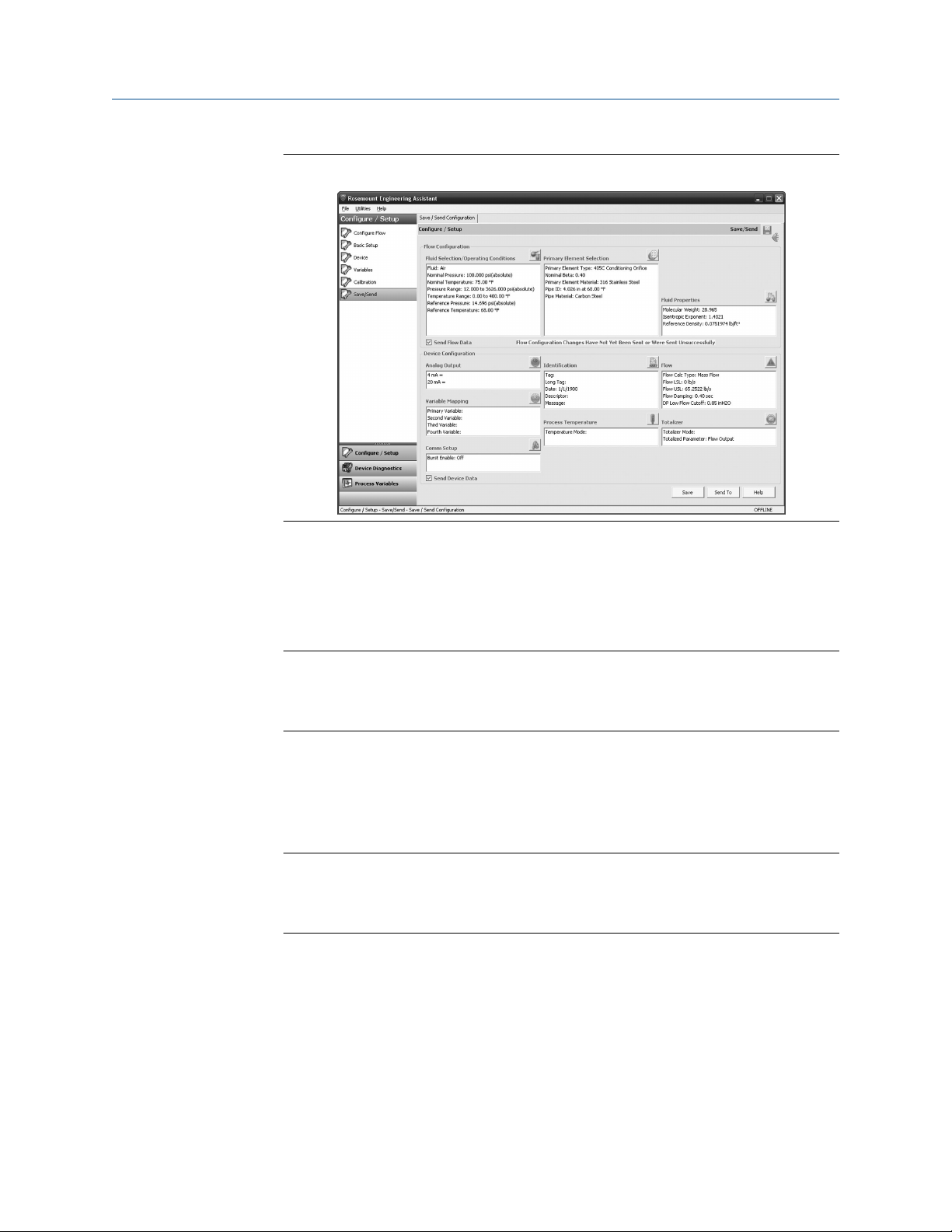
2.4.8
Save/send
About this task
The Save/Send Configuration tab shown in Figure 2-11 allows the user to view, save, and
send the configuration information to the Rosemount 3051SMV with the fully
compensated mass and energy flow feature board.
Procedure
1. Review the information under the Flow Configuration heading and Device
Configuration heading.
Note
For more information on device configuration, see Basic device configuration.
22 Rosemount 3051S Multivariable Transmitter
Page 23
Reference Manual Configuration
00809-0100-4803 October 2018
Figure 2-11: Save/Send Configuration Tab (Offline Mode)
2. Select the icon above each window to be taken to the appropriate screen to edit the
configuration information. To return to the Save/Send tab, select Save/Send in the
left menu.
3. When all information is correct, see Sending a configuration in offline mode or
Sending a configuration in online mode.
Note
The user will be notified if the configuration has been modified since it was last sent
to the transmitter. A warning message will be shown to the right of the Send Flow
Data and/or Send Device Data check boxes.
Sending a configuration in offline mode
Procedure
1. To send the configuration, select the Send To button.
Note
The Send Flow Data and/or Send Device Data check boxes can be used to select
what configuration data is sent to the transmitter. If the check box is unselected,
the corresponding data will not be sent.
2. The Engineering Assistant Device Connection screen will appear, see Figure 2-12.
Emerson.com/Rosemount 23
Page 24
Configuration Reference Manual
October 2018 00809-0100-4803
Figure 2-12: Engineering Assistant Device Connection Screen
3. Select the Search button located in the lower right corner of the screen.
Engineering Assistant will begin to search for connected devices.
4. When the search is completed, select the device to communicate with and select
Send Configuration button.
5. Once the configuration is finished being sent to the device, a notification appears.
6. If finished with the configuration process, close Engineering Assistant.
Note
After the configuration is sent to the device, saving the configuration file is
recommended. For more information on saving a configuration file, see Saving a
configuration.
Sending a configuration in online mode
Procedure
1. To send the configuration, select the Send button. Once the configuration is
finished being sent to the device, a notification appears.
2. If finished with the configuration process, close Engineering Assistant.
Note
After the configuration is sent to the device, saving the configuration file is
recommended. For more information on saving a configuration file, see Saving a
configuration.
Saving a configuration
Procedure
1. To save the configuration, select the Save button.
24 Rosemount 3051S Multivariable Transmitter
Page 25

Reference Manual Configuration
00809-0100-4803 October 2018
2. Navigate to the save location for the configuration file, give the file a name, and
select Save. The configuration will be saved as a “.smv” file type.
Sending a saved configuration
Procedure
1. To send a saved configuration, open Engineering Assistant in offline mode and
select File>Open.
2. Navigate to the saved .smv file to be sent. Select Open.
3. The Engineering Assistant Device Connection screen will appear, see Figure 2-12.
4. Select the Search button located in the lower right corner of the screen.
Engineering Assistant will begin to search for connected devices.
5. When the search is completed, select the device to communicate with and select
Send Configuration button.
6. Once the configuration is finished being sent to the device, a notification appears.
7. If finished with the configuration process, close Engineering Assistant.
2.4.9
Other fluid configurations
Natural gas AGA No. 8 detail characterization or ISO 12213, molar composition flow configuration
Procedure
1. Expand the Gas category.
2. Expand the Natural Gas category.
3. Select AGA Report No. 8 Detail Characterization Method or ISO 12213, Molar
Composition Method.
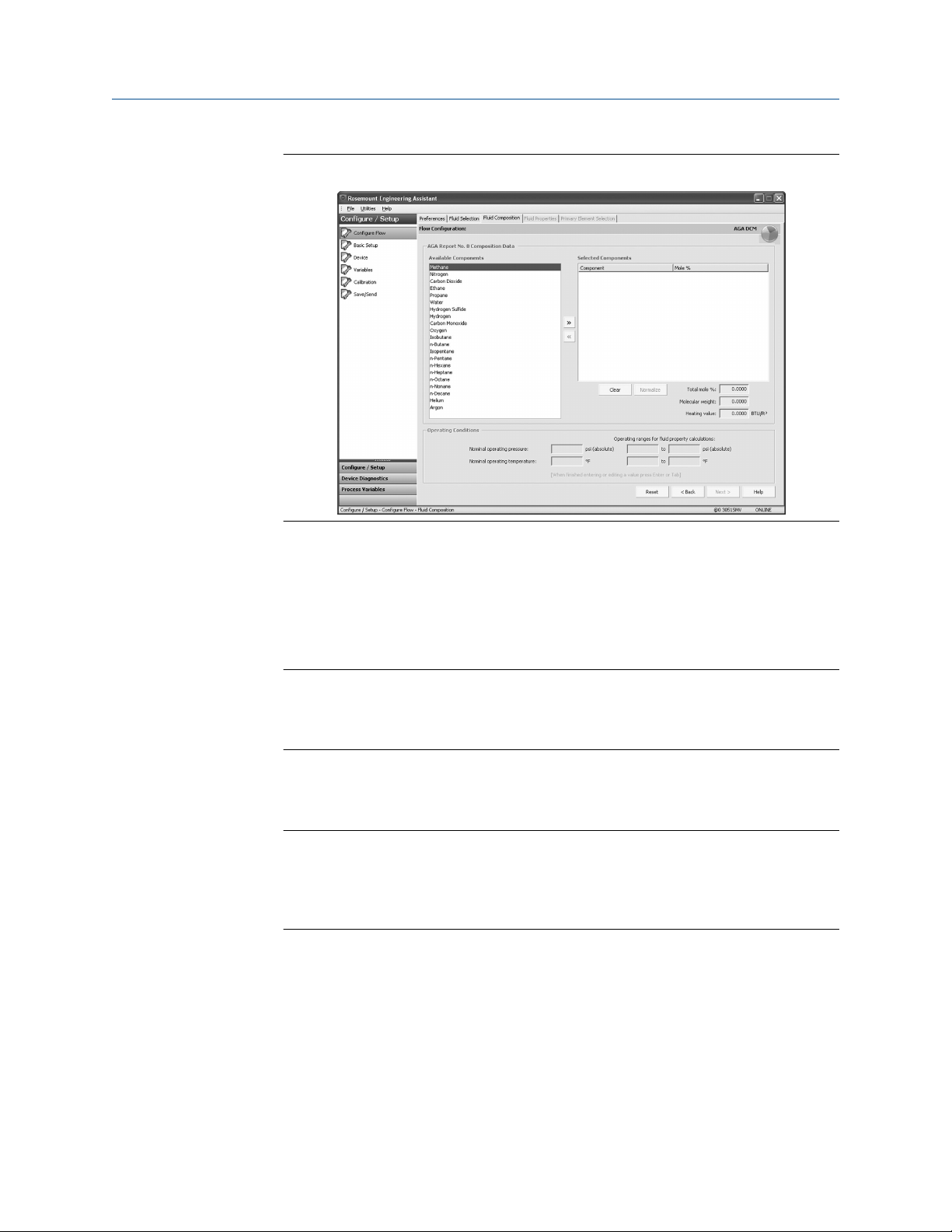
4. Select Next > to proceed to the Fluid Composition tab. Figure 2-13 shows an
example of the Fluid Composition tab for AGA Report No. 8 Detail Characterization
Method. The ISO 12213, Molar Composition Method Fluid Composition tab will
require the same information.
Emerson.com/Rosemount 25
Page 26
Configuration Reference Manual
October 2018 00809-0100-4803
Figure 2-13: Fluid Composition Tab
5. In the Available Components window, select the required components and move
them into the Selected Components window using the >> button. The << button
moves the components back to the Available Components window. The Clear
button moves all components back to the Available Components window.
6. After all required components are in the Selected Components window, begin
assigning the percent composition of each component in the Mole % column.
Note
These percent composition values should add to 100 percent. If they do not, select
the Normalize button. This will adjust the mole percentages proportionally to a
total of 100 percent.
7. Enter the Nominal Operating Pressure, then the Nominal Operating Temperature as
the entry blanks become available. Engineering Assistant will automatically fill in
suggested operating ranges. These values may be edited by the user.
Note
In order to comply with the AGA requirements the calculation accuracy must be
within ±50 ppm (±0.005%). This is stated in AGA Report No. 3, Part 4, Section 4.3.1.
The pressure and temperature operating ranges will be autofilled to comply with
the standard.
8. Select Next >. This will bring the user to the Fluid Properties tab.
9. Proceed with the steps in Fluid properties.
26 Rosemount 3051S Multivariable Transmitter
Page 27

Reference Manual Configuration
00809-0100-4803 October 2018
Natural gas AGA No. 8 gross characterization flow configuration method 1, method 2, and natural gas ISO 12213, physical properties (SGERG 88) flow configuration
Procedure
1. Expand the Gas category.
2. Select AGA No. 8 Gross Characterization Method 1, AGA No. 8 Gross
Characterization Method 2, or ISO 12213, Physical Properties (SGERG 88).
3. Select Next to proceed to the Fluid Composition tab.
4. Enter the required data for the Natural Gas Characterization Method that was
selected in Step 2. Required data for each method is listed in Table 2-3.
Table 2-3: Required and Optional Data for Natural Gas Characterization
Methods
Characterization
method
AGA Report No. 8 Gross
Characterization
Method 1
AGA Report No. 8 Gross
Characterization
Method 2
ISO 12213, Physical
Properties (SGERG 88)
(1) Reference conditions for the relative density are 60 °F (15.56 °C) and 14.73 psia (101.56
kPa).
(2) Reference conditions for the molar gross heating value are 60 °F (15.56 °C) and 14.73
psia (101.56 kPa) and reference conditions for molar density are 60 °F (15.56 °C) and
14.73 psia (101.56 kPa).
Required data Optional data
Relative Density
Volumetric Gross Heating Value
Relative Density
Mole Percent CO
Mole Percent Nitrogen
Relative Density
Volumetric Gross Heating Value
(1)
Mole Percent CO2
(1)
2
(1)
Mole Percent CO
(2)
(2)
Mole Percent CO Mole
Percent Hydrogen
Mole Percent CO Mole
Percent Hydrogen
Mole Percent CO Mole
2
Percent Hydrogen
5. If appropriate, enter the optional data for the Natural Gas Characterization Method
that was selected in Step 2. Optional data for each method is listed in Table 2-3.
6. Enter the Nominal Operating Pressure, then the Nominal Operating Temperature as
the entry blanks come available. Engineering Assistant will automatically fill in
suggested operating ranges. Note that these values may be edited by the user.
7. Select Next. This will open the Fluid Properties tab.
8. Proceed with the steps in Fluid properties.
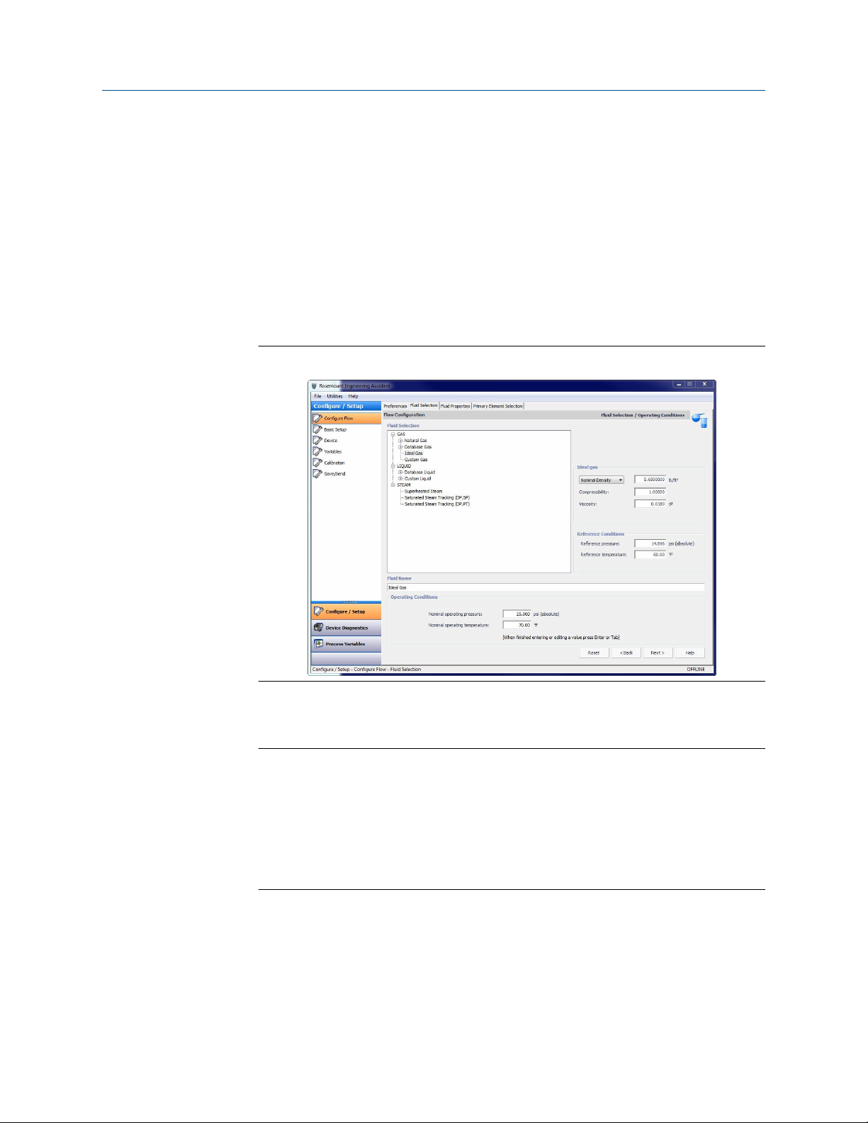
Ideal gas
The ideal gas option should be used when the fluid behavior can be modeled by the ideal
gas law. This option uses a modified version of the ideal gas law with a constant value of
compressibility. The default value for compressibility is 1.00 but it may be edited by the
user. To use an ideal gas enter in the operating pressure and temperature followed by
either the density, specific gravity, or molecular weight.
Emerson.com/Rosemount 27
Page 28
Configuration Reference Manual
October 2018 00809-0100-4803
Procedure
1. Expand the GAS category.
2. Select the Ideal Gas option.
3. Enter the Nominal Operating Pressure and Temperature Ranges. Engineering
Assistant will use these ranges to identify the pressure and temperature values at
which the fluid properties are required.
For the ideal gas being used the nominal density, specific gravity, or molecular
weight must now be entered using the drop-down menu. Once these are entered
the other data entry fields, compressibility and viscosity, are enabled as shown on
Figure 2-14.
Figure 2-14: Fluid Selection Ideal Gas
4. Adjust the compressibility and viscosity to fit the ideal gas of the process.
5. Select Next to proceed to the Fluid Properties tab.
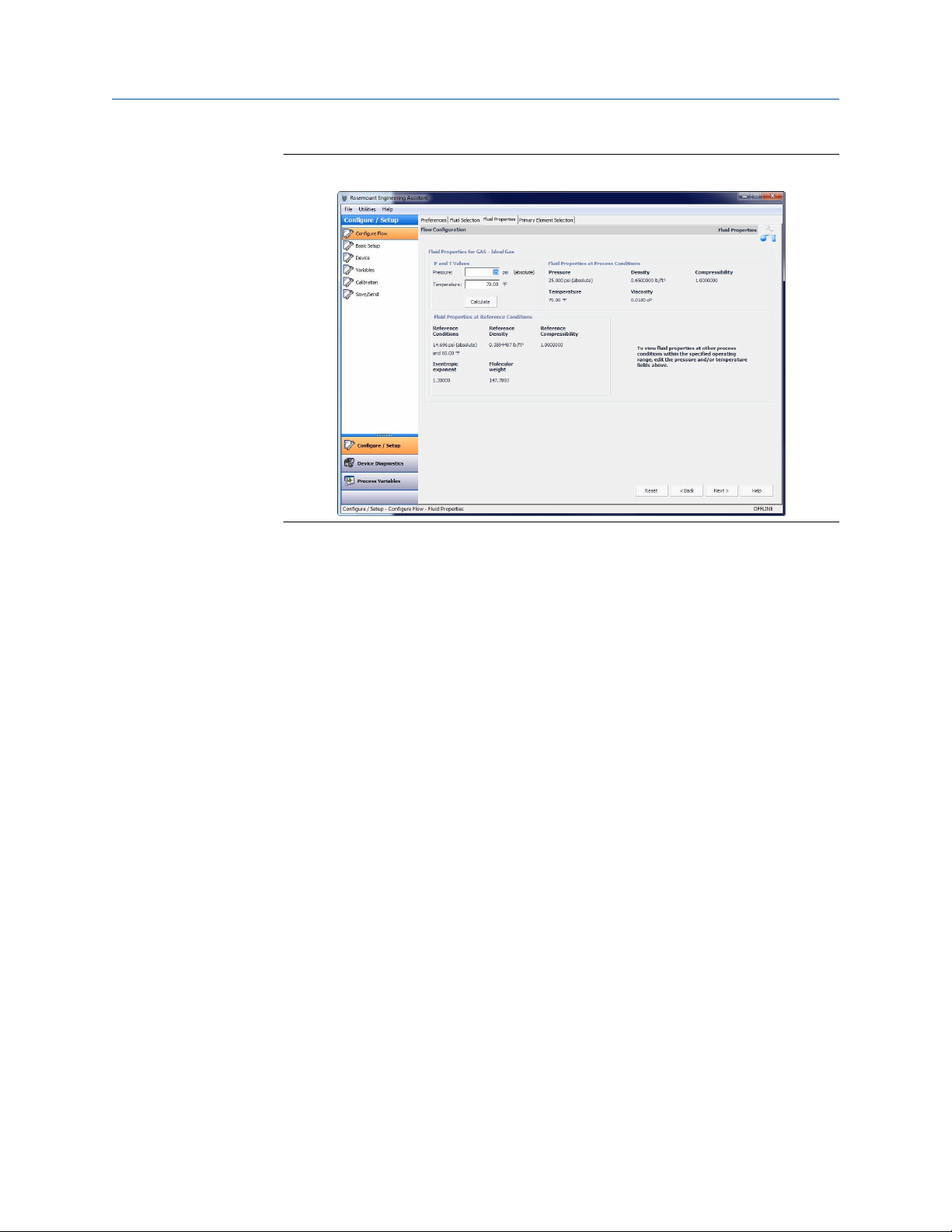
Note
The Fluid Properties tab is an optional step and is not required to complete a flow
configuration. The Fluid Properties tab for the database gas air is shown in Figure
2-15. The user may view the properties of the chosen fluid. The fluid properties are
initially shown at nominal conditions. To view density, compressibility, and viscosity
of the selected fluid at other pressure and temperature values, enter a Pressure and
Temperature and select Calculate. Changing the pressure and temperature values
on the Fluid Properties tab does not affect the flow configuration.
28 Rosemount 3051S Multivariable Transmitter
Page 29
Reference Manual Configuration
00809-0100-4803 October 2018
Figure 2-15: Fluid Properties Tab
6. Select Next to continue with the flow configuration on the Primary Element
Selection tab.
7. Proceed with the steps in Primary element selection.
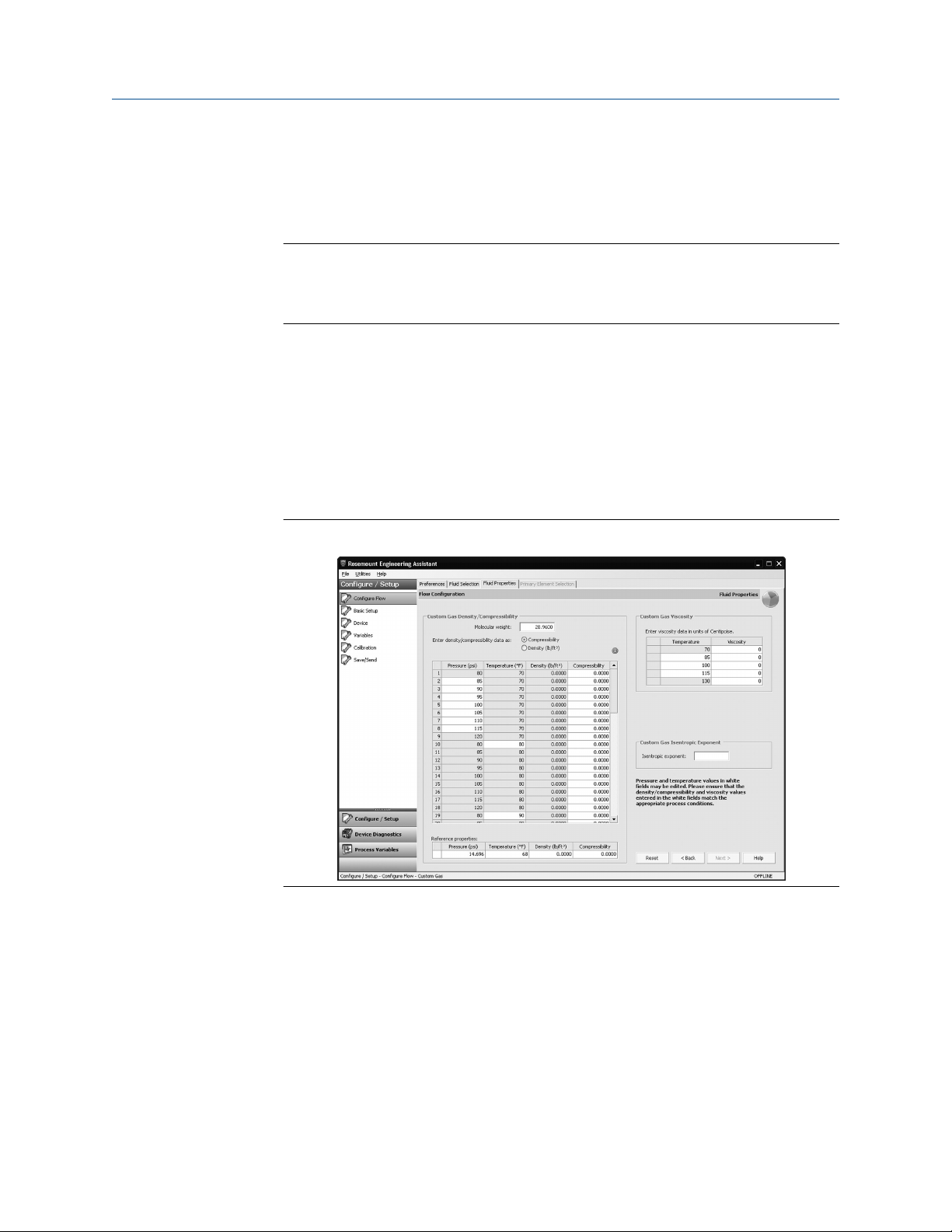
Custom gas
About this task
The custom gas option should be used for fluids not in the database such as proprietary
fluids or gas mixtures. To properly calculate the fluid properties, the compressibility factor
or density needs to be entered at specific pressure and temperature values based on the
operating ranges entered by the user. The pressure and temperature values may be edited
as needed. The editable values are shown in fields with white backgrounds. For best
performance, it is recommended that, whenever possible, the compressibility or density
values be entered at the suggested pressure and temperature values.
To ease entering the compressibility/density or viscosity values, data can be copied from a
spreadsheet and pasted into the grid. The recommended process is to copy the pressure
and temperature values from the table on the Engineering Assistant screen to assist in
computing the density or compressibility values. Once the compressibility or density
values are computed, they may then be copied from the spreadsheet and pasted into the
grid on the Custom Gas Fluid Properties tab.
Procedure
1. Expand the Gas category.
2. Select the Custom Gas option.
3. Enter the Nominal Operating Pressure and Temperature Ranges. Engineering
Assistant will use these ranges to identify the pressure and temperature values at
which the fluid properties are required.
4. Select Next to proceed to the Custom Gas Fluid Properties tab.
Emerson.com/Rosemount 29
Page 30
Configuration Reference Manual
October 2018 00809-0100-4803
5. Enter the Molecular Weight of the Custom Gas. When the molecular weight of the
gas is entered, the other data entry fields on the tab are enabled as shown in Figure
2-16.
6. Select either Density or Compressibility and enter data.
Note
All pressure and temperature values may be edited except the minimum and
maximum values. The minimum and maximum values were set on the Fluid
Selection tab.
7. Enter the Density or Compressibility at reference conditions.
8. Enter the Custom Gas Viscosity at the given temperatures. Note that all
temperature values may be edited except the minimum and maximum
temperatures.
9. Enter the Custom Gas Isentropic Exponent.
10. Select Next to continue with the flow configuration on the Primary Element
Selection tab.
11. Proceed with the steps in Primary element selection.
Figure 2-16: Custom Gas Fluid Properties Tab
Custom liquid (Density [T])
About this task
The Custom Liquid option should be used for fluids not in the database such as proprietary
fluids.
Procedure
1. Expand the Liquid category.
2. Expand the Custom Liquid category.
30 Rosemount 3051S Multivariable Transmitter
Page 31

Reference Manual Configuration
00809-0100-4803 October 2018
3. Select the Custom Liquid (Density [T]) option.
4. Enter the Nominal and Operating Temperature Range. Engineering Assistant will
use this range to identify the temperature values at which the fluid properties are
required.
5. Select Next to continue the flow configuration on the Fluid Properties tab.
6. Enter the Custom Liquid Density at the given temperatures.
Note
All temperature values may be edited except the minimum and maximum
temperatures.
7. Enter the Reference Density at the reference temperature.
8. Enter the Custom Liquid Viscosity at the given temperatures. Note that all
temperature values may be edited except the minimum and maximum
temperatures. The minimum and maximum values were set on the Fluid Selection
tab.
9. Proceed with the steps in Primary element selection.
Figure 2-17: Custom Liquid (Density [T]) Fluid Properties Tab
2.5 Basic device configuration
Mass and energy flow Fast Keys 1, 3
Direct process variable output Fast Keys 1, 3
This section provides procedures for configuring the basic requirements to commission
the Rosemount 3051SMV. The Basic Setup tab, shown in Figure 2-18, can be used to
perform all of the required transmitter configuration. The complete list of Field
Communicator Fast Keys for basic setup are shown in Field Communicator Fast Keys.
Emerson.com/Rosemount 31
Page 32

Configuration Reference Manual
October 2018 00809-0100-4803
Based on the configuration ordered, some measurements (i.e. static pressure, process
temperature) and/or calculation types (i.e. mass, volumetric, and energy flow) may not be
available for all fluid types. Available measurements and/or calculation types are
determined by the multivariable type and measurement type codes ordered. See Ordering
information for more information.
All screens in this section are shown for multivariable type M (fully compensated mass and
energy flow) with measurement type 1 (differential pressure, static pressure, and process
temperature). Field Communicator Fast Keys are given for both multivariable type M and P
(direct process variable output) with measurement type 1. Field Communicator Fast Keys
and screens for other multivariable types and measurement types may vary.
Note
All screen shots in this section will be shown using AMS Device Manager. Engineering
Assistant screens are similar and the instructions shown here apply to both AMS Device
Manager and Engineering Assistant.
When using Engineering Assistant, a Reset Page button will be shown. In online mode, the
Reset Page button will return all values on tab to the initial values received from the device
before the start of the configuration. If editing a previously saved configuration, the Reset
Page button will return all values on tab to those that were last saved. If starting a new
configuration, all entered values on tab will be erased.
CAUTION
When information is edited on any AMS Device Manager tab, it will be highlighted in
yellow. Edited information is not sent to the transmitter until the Apply or OK button is
selected.
32 Rosemount 3051S Multivariable Transmitter
Page 33

Reference Manual Configuration
00809-0100-4803 October 2018
2.5.1 Units of measure
If a unit of measure is edited and the Apply button is selected, the unit of measure will be
changed in the device memory and on screen, but the value may take up to 30 seconds to
be updated on the AMS Device Manager screen.
Figure 2-18: Basic Setup Tab
• Verify the Device Tag information. The tag information is used to identify specific
transmitters on the 4–20 mA loop. This tag information may be edited.
• Under the Flow Rate heading (fully compensated mass and energy flow feature board
only), the type of flow calculation (mass or volumetric) is displayed by the indicators on
the right side of the box. The Flow Calculation Type may be edited by selecting the
Configure Flow Calculation Type button. The Damping and Units of the Flow Rate may
also be edited under this heading.
Note
The flow calculation within the device uses undamped process variables. Flow rate
damping is set independently of measured process variables.
• Under the Energy Rate heading (fully compensated mass and energy flow feature
board only), the Units and Damping for the Energy Rate may be edited.
Note
Energy rate calculations are only available for steam and natural gas. The energy rate
calculation within the device uses undamped process variables. Energy rate damping is set
independently of flow rate damping or measured process variables.
• Under the Differential Pressure heading, the Units and Damping for the Differential
Pressure may be edited.
• Under the Static Pressure heading, the Units for both absolute and gage pressure and
static pressure Damping may be edited.
Note
Both absolute and gage pressure are available as variables. The type of transmitter ordered
will determine which variable is measured and which is calculated based on the user
Emerson.com/Rosemount 33
Page 34

Configuration Reference Manual
October 2018 00809-0100-4803
defined atmospheric pressure. For more information on configuring the atmospheric
pressure, see Static pressure. Since only one of the static pressures is actually being
measured, there is a single damping setting for both variables which may be edited under
the Static Pressure heading.
• Under the Process Temperature heading, the Units and Damping for the Process
Temperature may be edited.
• Under the Module Temperature heading, the Units for the sensor module temperature
may be set. The sensor module temperature measurement is taken within the module,
near the differential pressure and/or static pressure sensors and can be used to control
heat tracing or diagnose device overheating.
• Under the Analog Output heading, the primary variable can be selected from the drop
down menu and the upper and lower range values (4 and 20 mA points) for the primary
variable may be edited.
• Under the Totalizer heading (fully compensated mass and energy flow feature board
only), the Totalizer can be configured by selecting the Configure Totalizer button. This
button allows the user to select the variable to be totalized. The Totalizer Units may
also be edited under this heading.
2.6 Detailed device configuration
2.6.1 Model identification
Mass and energy flow Fast Keys 1, 3, 5
Direct process variable output Fast Keys 1, 3, 5
The Identification tab displays the device identification information on one screen. The
fields with white backgrounds may be edited by the user.
Figure 2-19: Device - Identification Tab
34 Rosemount 3051S Multivariable Transmitter
Page 35

Reference Manual Configuration
00809-0100-4803 October 2018
2.6.2 Alarm and saturation
The Rosemount 3051SMV automatically and continuously performs self-diagnostic
routines. If the self-diagnostic routines detect a failure, the transmitter drives the output
to the configured alarm value. The transmitter will also drive the output to configured
saturation values if the primary variable goes outside the 4–20 mA range values.
The alarm and saturation settings can be configured using Engineering Assistant, AMS
Device Manager, or a Field Communicator. See Alarm and saturation level configuration
for more information. The alarm direction can be configured using the hardware switch on
the feature board. See Configure security (write protect) for more information on the
hardware switch.
The Rosemount 3051SMV has three options for alarm and saturation levels:
• Rosemount (Standard), see Table 2-4
• NAMUR, see Table 2-5
• Custom (user-defined), see Table 2-6
Table 2-4: Rosemount (Standard) Alarm and Saturation Values
Level Saturation Alarm
Low 3.9 mA ≤ 3.75 mA
High 20.8 mA ≥ 21.75 mA
Table 2-5: NAMUR-Compliant Alarm and Saturation Values
Level Saturation Alarm
Low 3.8 mA ≤ 3.6 mA
High 20.5 mA ≥ 22.5 mA
Table 2-6: Custom Alarm and Saturation Values
Level Saturation Alarm
Low 3.7 mA — 3.9 mA 3.6 mA — 3.8 mA
High 20.1 mA — 22.9 mA 20.2 mA — 23.0 mA
The following limitations exist for custom levels:
• Low alarm level must be less than the low saturation level
• High alarm level must be higher than the high saturation level
• Alarm and saturation levels must be separated by at least 0.1 mA
Alarm and saturation level configuration
Mass and energy flow Fast Keys
Direct process variable output Fast Keys 1, 4, 2, 6, 6
1, 4, 2, 6, 6
The Alarm/Sat Levels tab allows the Alarm and Saturation Levels to be configured. To
change alarm/saturation level settings, select the Config Alarm/Sat Levels button.
Emerson.com/Rosemount 35
Page 36

Configuration Reference Manual
October 2018 00809-0100-4803
Figure 2-20: Device - Alarm/Sat Levels Tab
Alarm level verification
The transmitter alarm level should be verified before returning the transmitter to service if
alarm and saturation levels are changed.
This feature is also useful in testing the reaction of the control system to a transmitter in
an alarm state. To verify the transmitter alarm values, perform a loop test and set the
transmitter output to the alarm value (see Alarm and saturation and Analog output loop
test).
Variable saturation behavior
The analog output of the Rosemount 3051SMV may respond differently based on which
measurement goes outside the sensor limits. This response will also depend on the device
configuration. Table 2-7 lists the behaviors of the analog output under different
conditions.
Table 2-7: Variable Saturation Behavior
Primary variable Action Analog output behavior
Flow or Energy
Flow
Flow or Energy
Flow
Flow or Energy
Flow
Differential Pressure goes outside the
sensor limits
Absolute Pressure or Gage Pressure
goes outside the sensor limits
Process Temperature goes outside the
user defined sensor limits
Analog output goes to high or low
saturation
Analog output does not saturate
Temperature mode is Normal: Analog
output goes into high or low alarm.
Temperature Mode is Backup: The
Process Temp will go into backup
mode and be fixed at the user defined
value. Analog output will not saturate
or go into alarm.
36 Rosemount 3051S Multivariable Transmitter
Page 37

Reference Manual Configuration
00809-0100-4803 October 2018
Table 2-7: Variable Saturation Behavior (continued)
Primary variable Action Analog output behavior
DP Differential Pressure goes outside the
sensor limits
AP or GP Absolute Pressure or Gage Pressure
goes outside the sensor limits
Process Temp Process Temperature goes outside the
user defined sensor limits
2.6.3 Variable mapping
Mass and energy flow Fast Keys 1, 4, 3, 4
Direct process variable output Fast Keys 1, 4, 3, 4
The Variable Mapping tab is used to define which process variable will be mapped to each
HART variable. The primary variable represents the 4–20 mA analog output signal while
the 2nd, 3rd, and 4th variables are digital. To edit the variable assignments, select the
appropriate process variables from the drop-down menus and select Apply.
Figure 2-21: Device - Variable Mapping Tab
Analog output goes to high or low
saturation
Analog output goes to high or low
saturation
Direct process variable output: Analog
output goes to high or low saturation
Mass and Energy Flow: Analog output
goes to high or low alarm
2.6.4
LCD display
Mass and energy flow Fast Keys 1, 3, 8
Direct process variable output Fast Keys 1, 3, 8
The LCD display features a four-line display and a 0–100 percent scaled bar graph. The first
line of five characters displays the output description, the second line of seven digits
Emerson.com/Rosemount 37
Page 38

Configuration Reference Manual
October 2018 00809-0100-4803
displays the actual value, and the third line of six characters displays engineering units. The
fourth line displays “Error” when there is a problem detected with the transmitter. The
LCD display can also show diagnostic messages. These diagnostic messages are listed in
Table 5-1.
The LCD tab allows the user to configure which variables will be shown on the LCD display.
Select the check box next to each variable to select a variable for display. The transmitter
will scroll through the selected variables, showing each for three seconds.
Figure 2-22: Device - LCD Tab
2.6.5 Communication setup
Mass and energy flow Fast Keys 1, 4, 3, 3
Direct process variable output Fast Keys 1, 4, 3, 3
The Comm Setup tab allows the settings for burst mode and multidrop communications
to be configured.
38 Rosemount 3051S Multivariable Transmitter
Page 39

Reference Manual Configuration
00809-0100-4803 October 2018
Figure 2-23: Device - Comm Setup Tab
Burst mode
When Burst Mode Enable is set to on, the Rosemount 3051SMV sends up to four HART
variables to the control system without the control system polling for information from
the transmitter.
When operating with Burst Mode Enable set to on, the transmitter will continue to output
a 4–20 mA analog signal. Because the HART protocol features simultaneous digital and
analog data transmission, the analog value can drive other equipment in the loop while
the control system is receiving the digital information. Burst mode applies only to the
transmission of dynamic data (process variables in engineering units, primary variable in
percent of range, and/or analog output), and does not affect the way other transmitter
data is accessed.
Access to information that is not burst can be obtained through the normal poll/response
method of HART communication. A Field Communicator, AMS Device Manager,
Engineering Assistant, or the control system may request any of the information that is
normally available while the transmitter is in burst mode.
Enabling burst mode
Mass and energy flow Fast Keys
Direct process variable output Fast Keys 1, 4, 3, 3, 3
To enable burst mode, select On from the Burst Mode Enable drop-down menu under the
Burst Mode heading.
1, 4, 3, 3, 3
Choosing a burst option
Mass and energy flow Fast Keys
Direct process variable output Fast Keys 1, 4, 3, 3, 4
Emerson.com/Rosemount 39
1, 4, 3, 3, 4
Page 40

Configuration Reference Manual
October 2018 00809-0100-4803
This parameter selects the information to be burst. Make a selection from the Burst Option
drop-down menu under the Burst Mode heading. The Dyn vars/current option is the most
common, because it is used to communicate with the Rosemount 333 HART Tri-Loop™ .
Table 2-8: Burst Options
HART command Burst option Description
1 PV Primary variable
2 % range/current Percent of range and milliamp output
3 Dyn vars/current All process variables and milliamp output
9 Device vars w/ status Burst variables and status information
33 Device variables Burst variables
Choosing burst variable slot definition
Mass and energy flow Fast Keys
Direct process variable output Fast Keys 1, 4, 3, 3, 5
1, 4, 3, 3, 5
If the burst option Device vars w/ status or Device variables is selected, the user may select
the four variables that will be burst. These are defined in slots 1–4 under the Burst Variable
Slot Definitions heading. The variables defined in slots 1–4 can be different than the
variables mapped to the primary, 2nd, 3rd, and 4th variable outputs.
Multidrop communication
Multidropping transmitters refers to the connection of several transmitters to a single
communications transmission line.
Note
Figure 2-24 shows a typical multidrop network. This figure is not intended as an
installation diagram.
Communication between the host and the transmitters takes place digitally with the
analog output of the transmitters deactivated.
Note
A transmitter in multidrop mode with Loop Current Mode disabled has the analog output
fixed at 4 mA.
40 Rosemount 3051S Multivariable Transmitter
Page 41

Reference Manual Configuration
00809-0100-4803 October 2018
Figure 2-24: Typical Multidrop Network
A. Power supply
B. HART modem
Enable multidrop communication
2.6.6
Mass and energy flow Fast Keys
Direct process variable output Fast Keys 1, 4, 3, 3, 1
The Rosemount 3051SMV is set to address zero (0) at the factory, which allows operation
in the standard point-to-point manner with a 4–20 mA output signal. To activate
multidrop communication, the transmitter address must be changed to 1–15 for HART 5
hosts or 1–63 for HART 6 hosts. This change deactivates the 4–20 mA analog output,
sending it to a fixed value of 4 mA. It also disables the failure alarm signal, which is
controlled by the HI/LO alarm switch position on the feature board. Failure signals in
multidropped transmitters are communicated through HART messages.
1, 4, 3, 3, 1
Loop current mode
Mass and energy flow Fast Keys
Direct process variable output Fast Keys 1, 4, 3, 3, 2
When using multidrop communication, the loop current mode drop-down menu defines
how the 4–20 mA analog output behaves. When loop current mode is disabled, the analog
output will be fixed at 4 mA. When the loop current mode is enabled, the analog output
will follow the primary variable.
1, 4, 3, 3, 2
Materials of construction
Mass and energy flow Fast Keys 1, 4, 4, 2
Direct process variable output Fast Keys 1, 4, 4, 2
The Materials of Construction tab allows the materials of construction, remote seal, and
equipped sensor information to be viewed. The parameters shown in white boxes may be
edited by the user, but do not affect the operation of the device.
Emerson.com/Rosemount 41
Page 42

Configuration Reference Manual
October 2018 00809-0100-4803
Figure 2-25: Device - Materials of Construction Tab
2.6.7 Flow configuration parameters
Mass and energy flow Fast Keys 1, 4, 4, 3
(Fully compensated mass and energy flow feature board only)
The Flow Config Parameters tab allows the Process Fluid, Primary Element type and Pipe
Diameter used in the flow configuration to be viewed. These values may only be edited
using Engineering Assistant version 6.3 or later.
Figure 2-26: Device - Flow Config Parameters Tab
42 Rosemount 3051S Multivariable Transmitter
Page 43

Reference Manual Configuration
00809-0100-4803 October 2018
2.7 Variable configuration
2.7.1 Flow rate
About this task
Mass and energy flow Fast Keys 1, 4, 1, 1
(Fully compensated mass and energy flow feature board only)
The Flow tab is used to configure the settings associated with the Flow Variable. Fluid and
primary element information which defines the flow calculation is configured using
Engineering Assistant.
Figure 2-27: Variables - Flow Tab
• Under the Flow Rate Setup heading, the type of flow calculation is indicated by the
check boxes next to either Mass Flow Calculation or Volumetric Flow Calculation. To
edit the flow calculation type, select the Configure Flow Calculation Type button.
• Edit the Flow Rate Units and Damping value as needed. The flow calculation within the
device uses undamped process variables. Flow rate damping is set independently of
the measured process variables.
Note
If the flow calculation type is changed, the totalizer will be stopped and reset
automatically.
• Under the Low Flow Cutoff heading, edit the current Minimum DP Value as needed.
The unit for this value is the user-selected DP unit. If the measured DP value is less than
the minimum DP value, the transmitter will calculate the Flow Rate value to be zero.
• The Sensor Limits and Minimum Span can be viewed under the Flow Rate Sensor Limits
heading.
Emerson.com/Rosemount 43
Page 44

Configuration Reference Manual
October 2018 00809-0100-4803
Note
If the flow rate is configured as the primary variable and is being output via the 4–20 mA
signal, verify the 4–20 mA range (LRV and URV) after completing the custom unit
configuration. For more information on verifying the 4–20 mA range, see Basic device
configuration.
Follow these steps to configure a custom unit:
Procedure
1. Custom Unit: Enter the desired custom unit label to be displayed for the flow rate.
Up to five characters including letters, numbers, and symbols can be entered in the
custom unit field.
Note
It is recommended that the Custom Unit be entered in upper case letters. If lower
case letters are entered, the LCD display will show upper case letters. Additionally,
the following special characters are recognized by the LCD display: hyphens (“-”),
percent symbols (“%”), asterisks (“*”), forward slashes (“/”) and spaces. Any other
character entered for the Custom Unit will be displayed as an asterisk (“*”) on the
LCD display. The following warning will be returned indicating these changes:
“Custom Unit contains characters that will display in upper case or asterisks on LCD
display. The DCS will display as entered.”
2. Base Unit: From the drop-down menu, select a base unit to be used for the custom
unit relationship.
3. Base per Custom: Enter a numeric value that represents the number of base units
per one custom unit. The Rosemount 3051SMV uses the following convention: Base
per Custom =
Example
Custom Unit: kg Base Unit: g
Because:
1 kg (Kilogram) = 1000 g (Grams)
Base per Custom =
= = 1000
The values of Base per Custom for common flow units are shown in Table 2-9.
4. Select
Apply
.
5. Flow Rate Unit: From the drop-down menu, select the custom unit that was
created in Step 2.
Results
Note
The custom unit may not be available as a selection in the Flow Rate Unit drop-down menu
until the drop-down menu is refreshed. To refresh the drop- down menu, navigate to the
Basic Setup tab and then return to the Variables - Flow tab.
44 Rosemount 3051S Multivariable Transmitter
Page 45

Reference Manual Configuration
00809-0100-4803 October 2018
Table 2-9: Common Custom Units - Flow
Custom unit Base unit Base per custom
Barrels per Minute (BBL/M) bbl/h 60
Cubic Meters per Day (CUM/D) Cum/h 0.041667
Millions of Cubic Meters per Day (MMCMD) Cum/h 41666.7
Millions of Gallons per Day (MGD) gal/d 1000000
Millions of Liters per Day (MML/D) L/h 41666.7
Millions of Standard Cubic Feet per Day (MMCFD) StdCuft/min 694.444
Normal Cubic Meters per Day (NCM/D) NmlCum/h 0.041667
Normal Cubic Meters per Minute (NCM/M) NmlCum/h 60
Short Tons per Day (STOND) lb/d 2000
Short Tons per Hour (STONH) lb/h 2000
Standard Cubic Feet per Day (SCF/D) StdCuft/min 0.000694
Standard Cubic Feet per Hour (SCF/H) StdCuft/min 0.016667
Standard Cubic Feet per Second (SCF/S) StdCuft/min 60
Standard Cubic Meters per Day (SCM/D) StdCum/h 0.041667
Thousands of Gallons per Day (KGD) gal/d 1000
Thousands of Pounds per Hour (KLB/H) lb/h 1000
Thousands of Standard Cubic Feet per Day (KSCFD) StdCuft/min 0.694444
Thousands of Standard Cubic Feet per Hour (KSCFH) StdCuft/min 16.6666
If conversion factor tables or internet search engines are used to determine the Base per
Custom value, it is important to enter the Custom Unit in the “From” field and the Base
Unit in the “To” Field. An example of this is shown below:
To calculate the Base per Custom value for a custom unit not shown in Table 2-9, see one
of the following examples:
Emerson.com/Rosemount 45
Page 46

Configuration Reference Manual
October 2018 00809-0100-4803
• Mass/volume conversion example: Mass/volume conversion example
• Time conversion example: Time conversion example
• Mass/volume and time conversion example: Mass/volume and time conversion
example
Mass/volume conversion example
To find the Base per Custom relationship for a custom unit of kilograms per hour (kg/h)
and a base unit of grams per hour (g/h), input the following:
Custom Unit = kg/h Base Unit = g/h
Because:
1 kg (Kilogram) = 1000 g (Grams)
Then: 1 kg/h = × = 1000 g/h
1 kg/h = 1000 g/h
Therefore:
Base per Custom = = = 1000
Figure 2-28: Flow Rate Custom Units - Mass/Volume Conversion Example
Time conversion example
To find the Base per Custom relationship for a custom unit of standard cubic feet per hour
(scf/h) and a base unit of standard cubic feet per minute (StdCuft/min), input the
following:
Custom Unit = scf/h Base Unit = StdCuft/min
Because:
46 Rosemount 3051S Multivariable Transmitter
Page 47

Reference Manual Configuration
00809-0100-4803 October 2018
1 h (Hour) = 60 min (Minutes)
Then: 1 scf/h = × = 0.016667 StdCuft/min
1 scf/h = 0.016667 StdCuft/min
Therefore:
Base per Custom = = = 0.016667
Figure 2-29: Flow Rate Custom Units - Time Conversion Example
Mass/volume and time conversion example
To find the Base per Custom relationship for a custom unit of standard millions of standard
cubic feet per day (mmcfd) and a base unit of standard cubic feet per minute (StdCuft/
min), input the following:
Custom Unit = mmcfd Base Unit = StdCuft/min
Because:
1 mmcf (Millions of Standard Cubic Feet) = 1000000 StdCuft (Standard Cubic Feet) and
1 d (Day) = 1440 min (Minutes)
Then:
1 mmcfd = × × = 694.444 StdCuft/min
1 mmcfd = 694.444 StdCuft/min
Therefore:
Base per Custom = = = 694.444
Emerson.com/Rosemount 47
Page 48

Configuration Reference Manual
October 2018 00809-0100-4803
Figure 2-30: Flow Rate Custom Units - Mass/Volume and Time Conversion Example
Under the Custom Units Setup heading, the user may configure a custom unit for the flow
rate measurement. Custom units allow the flow rate to be displayed in units of measure
that are not standard in the Rosemount 3051SMV.
2.7.2
Energy rate
About this task
Mass and energy flow Fast Keys
(Fully compensated mass and energy flow feature board only)
Note
Energy Rate calculations are only available for certain fluid types.
The Energy tab allows the user to configure the settings associated with the energy flow.
• Under the Energy Rate Setup heading, edit the Energy Rate Units and Damping values
as needed. The energy rate calculation within the device uses undamped process
variables. Energy rate damping is set independently of flow rate damping and
measured process variables.
• Under the Custom Units Setup heading, the user may configure a custom unit for the
energy rate measurement. Custom units allow the energy rate to be displayed in units
of measure that are not standard in the Rosemount 3051SMV.
Note
If the energy rate is configured as the primary variable and is being output via the 4-20 mA
signal, verify the 4–20 mA range (LRV and URV) after completing the custom unit
configuration. For more information on verifying the 4–20 mA range, see Basic device
configuration.
1, 4, 1, 2
Follow these steps to configure a custom unit:
48 Rosemount 3051S Multivariable Transmitter
Page 49

Reference Manual Configuration
00809-0100-4803 October 2018
Procedure
1. Custom Unit: Enter the desired custom unit label to be displayed for the energy
rate. Up to five characters including letters, numbers, and symbols can be entered
in the custom unit field.
Note
It is recommended that the Custom Unit be entered in upper case letters If lower
case letters are entered, the LCD display will show upper case letters. Additionally,
the following special characters are recognized by the LCD display: hyphens (“-”),
percent symbols (“%”), asterisks (“*”), forward slashes (“/”) and spaces. Any other
character entered for the Custom Unit will be displayed as an asterisk (“*”) on the
LCD display. The following warning will be returned indicating these changes:
“Custom Unit contains characters that will display in upper case or asterisks on LCD
display. The DCS will display as entered.”
2. Base Unit: From the drop-down menu, select a base unit to be used for the custom
unit relationship.
3. Base per Custom: Enter a numeric value that represents the number of base units
per one custom unit. The Rosemount 3051SMV uses the following convention: Base
per Custom =
Example
Custom Unit: kg Base Unit: g
Because:
1 kg (Kilogram) = 1000 g (Grams)
Base per Custom = = = 1000 The values of
Base per Custom for common energy units are shown in Table 2-10.
4. Select Apply.
5. Energy Rate Unit: From the drop-down menu, select the custom unit that was
created in Step 2.
Example
Note
The custom unit may not be available as a selection in the Energy Rate Unit drop-down
menu until the drop-down menu is refreshed. To refresh the drop- down menu, navigate
to the Basic Setup tab and then return to the Variables - Energy tab.
Table 2-10: Common Custom Units - Energy Flow
Custom unit Base unit Base per custom
BTU per Day (BTU/D) Btu/h 0.041667
BTU per Minute (BTU/M) Btu/h 60
Megajoules per Day (MJ/D) MJ/h 0.041667
Emerson.com/Rosemount 49
Page 50

Configuration Reference Manual
October 2018 00809-0100-4803
Table 2-10: Common Custom Units - Energy Flow (continued)
Custom unit Base unit Base per custom
Megajoules per Minute (MJ/M) MJ/h 60
Thousands of BTU per Day (KBTUD) Btu/h 41.6667
Thousands of BTU per Hour (KBTUH) Btu/h 1000
If conversion factor tables or internet search engines are used to determine the Base per
Custom value, it is important to enter the Custom Unit in the “From” field and the Base
Unit in the “To” Field. An example of this is shown below:
To calculate the Base per Custom value for a custom unit not shown in Table 2-10, see one
of the following examples:
• Energy conversion example: Energy conversion example
• Time conversion example: Time conversion example
• Energy and time conversion example: Energy and time conversion example
Energy conversion example
To find the Base per Custom relationship for a custom unit of thousands of BTU per hour
(kBtuh) and a base unit of BTU per hour (Btu/h), input the following:
Custom Unit = kBtuh
Base Unit = Btu/h
Because:
1 kBtu (Thousands of BTU) = 1000 Btu
Then: 1 kBtuh = × = 1000 Btu/h
1 kBtuh = 1000 Btu/h
Therefore:
50 Rosemount 3051S Multivariable Transmitter
Page 51

Reference Manual Configuration
00809-0100-4803 October 2018
Base per Custom = = = 1000
Figure 2-31: Energy Rate Custom Units - Energy Conversion Example
Time conversion example
To find the Base per Custom relationship for a custom unit of standard cubic feet per hour
(scf/h) and a base unit of standard cubic feet per minute (StdCuft/min), input the
following:
Custom Unit = scf/h Base Unit = StdCuft/min
Because:
1 h (Hour) = 60 min (Minutes)
Then: 1 scf/h = × = 0.016667 StdCuft/min
1 scf/h = 0.016667 StdCuft/min
Therefore:
Base per Custom = = = 0.016667
Emerson.com/Rosemount 51
Page 52

Configuration Reference Manual
October 2018 00809-0100-4803
Figure 2-32: Flow Rate Custom Units - Time Conversion Example
Energy and time conversion example
To find the Base per Custom relationship for a custom unit of thousands of BTU per day
(kBtud) and a base unit of BTU per hour (Btu/h), input the following:
Custom Unit = kBtud Base Unit = Btu/h
Because:
1 kBtu (Thousands of BTU)= 1000 Btu and
1 d (Day) = 24 h (Hours)
Then:
1 kBtud = × × = 41.6667 Btu/h
1 kBtud = 41.6667 Btu/h
Therefore:
Base per Custom = = =
41.6667
52 Rosemount 3051S Multivariable Transmitter
Page 53

Reference Manual Configuration
00809-0100-4803 October 2018
Figure 2-33: Energy Rate Custom Units - Energy and Time Conversion Example
• Under the Low Flow Cutoff heading, edit the current Minimum DP Value as needed.
The unit for this value is the user-selected DP unit. If the measured DP value is less than
the minimum DP value, the transmitter will calculate the energy value to be zero.
• The Sensor Limits and Minimum Span can be viewed under the Energy Rate Sensor
Limits heading.
2.7.3
Totalizer
About this task
Mass and energy flow Fast Keys
(Fully compensated mass and energy flow feature board only)
The Totalizer tab is used to configure the settings associated with the totalizer
functionality within the transmitter.
1, 4, 1, 3
Emerson.com/Rosemount 53
Page 54

Configuration Reference Manual
October 2018 00809-0100-4803
Figure 2-34: Variables - Totalizer Tab
Procedure
1. To turn the totalizer functionality on or off, select Start or Stop from the Mode drop
down menu under the Totalizer Setup heading. The totalizer Units may also be
edited under this heading.
2. Verify the Totalized Parameter and the Totalizer Maximum value. To edit the
Totalized Parameter, select the Configure Totalizer button under the Totalizer
Control heading.
Note
When the totalizer reaches its maximum value, it automatically resets to zero and
continues totalizing. The default maximum is a value equivalent to 4.29 billion
pounds, actual cubic feet, or BTU. To edit the Totalizer Maximum value, select the
Set Totalizer Maximum button under the Totalizer Control heading.
3. To reset the Totalized Reading to zero, select the Reset Totalizer button under the
Totalizer Control heading.
4. Under the Custom Units Setup heading, the user may configure a custom unit for
the Totalized Reading. Custom units allow the totalizer rate to be displayed in units
of measure that are not standard in the Rosemount 3051SMV.
Note
If the totalizer rate is configured as the primary variable and is being output via the
4–20 mA signal, verify the 4–20 mA range (LRV and URV) after completing the
custom unit configuration. For more information on verifying the 4–20 mA range,
see Basic device configuration.
Follow these steps to configure a custom unit:
a) Custom Unit: Enter the desired custom unit label to be displayed for the
Totalized Reading. Up to five characters including letters, numbers, and
symbols can be entered in the custom unit field.
54 Rosemount 3051S Multivariable Transmitter
Page 55

Reference Manual Configuration
00809-0100-4803 October 2018
Note
It is recommended that the Custom Unit be entered in upper case letters. If
lower case letters are entered, the LCD display will show upper case letters.
Additionally, the following special characters are recognized by the LCD
display: hyphens (“-”), percent symbols (“%”), asterisks (“*”), forward slashes
(“/”) and spaces. Any other character entered for the Custom Unit will be
displayed as an asterisk (“*”) on the LCD display. The following warning will
be returned indicating these changes: “Custom Unit contains characters that
will display in upper case or asterisks on LCD display. The DCS will display as
entered.”
b) Base Unit: From the drop-down menu, select a base unit to be used for the
custom unit relationship.
c) Base per Custom: Enter a numeric value that represents the number of base
units per one custom unit. The Rosemount 3051SMV uses the following
convention: Base per Custom =
Example
Custom Unit: kg Base Unit: g
Because:
1 kg (Kilogram) = 1000 g (Grams)
Base per Custom = = = 1000 The values of
Base per Custom for common totalizer units are shown in Table 2-11.
d) Select Apply.
e) Totalizer Unit: From the drop-down menu, select the custom unit that was
created in 4.b.
Example
Note
The custom unit may not be available as a selection in the Totalizer Unit drop-down menu
until the drop-down menu is refreshed. To refresh the drop- down menu, navigate to the
Basic Setup tab and then return to the Variables - Totalizer tab.
Table 2-11: Common Custom Units - Totalizer
Custom unit Base unit Base per custom
Millions of Normal Cubic Meters (MMNCM) NmlCum 1000000
Millions of Standard Cubic Feet (MMSCF) StdCuft 1000000
Millions of Standard Cubic Meters (MMSCM) StdCum 1000000
Thousands of Metric Tons (KMTON) MetTon 1000
Thousands of Normal Cubic Meters (KNCM) NmlCum 1000
Thousands of Short Tons (KSTON) STon 1000
Thousands of Standard Cubic Feet (KSCF) StdCuft 1000
Emerson.com/Rosemount 55
Page 56

Configuration Reference Manual
October 2018 00809-0100-4803
Table 2-11: Common Custom Units - Totalizer (continued)
Custom unit Base unit Base per custom
Thousands of Standard Cubic Meters (KSCM) StdCum 1000
If conversion factor tables or internet search engines are used to determine the Base per
Custom value, it is important to enter the Custom Unit in the “From” field and the Base
Unit in the “To” Field.
To calculate the Base per Custom value for a custom unit not shown in Table 2-9, see the
example:
Totalizer conversion example
To find the Base per Custom relationship for a custom unit of millions of standard cubic
feet (mmscf) and a base unit of standard cubic feet (StdCuft), input the following:
Custom Unit = mmscf
Base Unit = StdCuft
Because:
1 mmscf (Millions of Standard Cubic Feet) = 1000000 StdCuft (Standard Cubic Feet)
Therefore:
Base per Custom =
Figure 2-35: Totalizer Custom Units - Totalizer Example
= = 1000000
2.7.4
56 Rosemount 3051S Multivariable Transmitter
Differential pressure
Mass and energy flow Fast Keys 1, 4, 1, 4
Direct process variable output Fast Keys 1, 4, 1, 1
Page 57

Reference Manual Configuration
00809-0100-4803 October 2018
Note
For differential pressure sensor calibration, see Differential pressure sensor calibration.
Figure 2-36: Variables - Differential Pressure Tab
2.7.5
• Under the Differential Pressure Setup heading, edit the DP Units and Damping value as
needed.
• The Sensor Limits and Minimum Span can be viewed under the Differential Pressure
Sensor Limits heading.
Static pressure
Mass and energy flow Fast Keys 1, 4, 1, 5
Direct process variable output Fast Keys 1, 4, 1, 2
Note
For static pressure sensor calibration, see Static pressure sensor calibration.
Emerson.com/Rosemount 57
Page 58

Configuration Reference Manual
October 2018 00809-0100-4803
Figure 2-37: Variables - Static Pressure Tab
• Under the Static Pressure Setup heading, edit the Absolute Pressure Units and Gage
Pressure Units as needed. The static pressure Damping may also be edited.
2.7.6
Note
The transmitter may be equipped with either an absolute or gage static pressure sensor
type depending on specified model code. The type of static pressure sensor equipped in
the transmitter can be determined by referring to the Static Pressure Sensor Type heading.
The static pressure type not being measured is a calculated value using the atmospheric
pressure value as specified under the User-Defined Atmospheric Pressure heading.
• The Sensor Limits and Minimum Span for the absolute and gage static pressure can be
viewed under the Sensor Limit headings.
Process temperature
Mass and energy flow Fast Keys 1, 4, 1, 6
Direct process variable output Fast Keys 1, 4, 1, 3
Note
For process teperature sensor calibration, see Process temperature sensor calibration . If a
transmitter was ordered with Fixed Process Temperature Only, the Fixed Temperature
Value and Units can be edited on the Fixed Temperature tab.
58 Rosemount 3051S Multivariable Transmitter
Page 59

Reference Manual Configuration
00809-0100-4803 October 2018
Figure 2-38: Variables - Process Temperature Tab
• Under the Process Temperature Setup heading, edit the Units and Damping value as
needed.
• Select the Temperature Mode under the Process Temperature Setup heading. See
Table 2-12.
Table 2-12: Temperature Modes
Temperature mode Description
Normal The transmitter will only use the actual measured Process Temperature value. If the
temperature sensor fails, the transmitter will put the analog signal into Alarm.
Backup The transmitter will use the actual measured Process Temperature value. If the
temperature sensor fails, the transmitter will use the value shown in the Fixed/
Backup Temperature field.
Fixed The transmitter will always use the temperature value shown in the Fixed/Backup
Temperature field.
Note
Process Temperature Mode Setup only applies to transmitters with fully compensated
mass and energy flow feature board.
• The Sensor Limits and Minimum Span can be viewed under the Process Temperature
Sensor Limits heading. The upper and lower sensor limits may be edited as needed.
The Rosemount 3051SMV accepts Callendar-Van Dusen constants from a calibrated RTD
schedule and generates a special custom curve to match that specific sensor Resistance
vs. Temperature performance. Matching the specific sensor curve with the transmitter
configuration enhances the temperature measurement accuracy.
Emerson.com/Rosemount 59
Page 60

Configuration Reference Manual
October 2018 00809-0100-4803
• Under the Sensor Matching heading, the Callendar-Van Dusen constants R0, A, B, and C
can be viewed. If the Callendar-Van Dusen constants are known for the user’s specific
Pt 100 RTD sensor, the constants R0, A, B, and C may be edited by selecting the
Callendar-Van Dusen Setup button and following the on-screen prompts. The user may
also view the α, β, and δ coefficients by selecting the View Alpha, Beta, Delta button.
The constants R0, α, β, and δ may be edited by selecting the Callendar-Van Dusen
Setup button and following the on-screen prompts. To reset the transmitter to the IEC
751 Defaults, select the Reset to IEC 751 Defaults button.
2.7.7 Module temperature
Mass and energy flow Fast Keys 1, 4, 1, 7
Direct process variable output Fast Keys 1, 4, 1, 4
The sensor module temperature variable is the measured temperature of the sensors and
electronics within the SuperModule assembly. The module temperature can be used to
control heat tracing or diagnose device overheating.
Figure 2-39: Variables - Module Temperature Tab
• Under the Module Temperature Setup heading, edit the Units as needed.
• The Sensor Limits can be viewed under the Module Temperature Sensor Limits
heading.
2.7.8
60 Rosemount 3051S Multivariable Transmitter
Analog output
About this task
Mass and energy flow Fast Keys
Direct process variable output Fast Keys 1, 4, 3, 2
1, 4, 3, 2
Page 61

Reference Manual Configuration
00809-0100-4803 October 2018
Note
For Analog calibration, see Analog calibration.
Figure 2-40: Variables - Analog Output Tab
Procedure
1. Select the Primary Variable under the Analog Output Setup heading. The Upper
Range Value and Lower Range Value may also be edited under this heading.
2. Verify the Upper Sensor Limit and Lower Sensor Limit and minimum span under the
Primary Variable Sensor Limits heading.
Transfer function (direct process variable output feature board only)
The Rosemount 3051SMV with direct process variable output feature board has two
analog output settings: Linear and Square Root. Activate the square root output option to
make analog output proportional to flow. As input approaches zero, the Rosemount
3051SMV automatically switches to linear output in order to ensure a smooth, stable
output near zero (see Figure 2-41).
From 0 to 0.6 percent of the ranged pressure input, the slope of the curve is unity (y = x).
This allows accurate calibration near zero. Greater slopes would cause large changes in
output (for small changes at input). From 0.6 to 0.8 percent, curve slope equals 41.72 (y =
41.72x) to achieve continuous transition from linear to square root at the transition point.
Note
Do not set both the analog output of the device and the control system to square root.
Emerson.com/Rosemount 61
Page 62

5.6
5.424
4.8
4.096
4
10
Full scale
flow (%)
Full scale output (mA dc)
8.9
5
0.6
0
0 0.6 0.8 1
Sq. root curve
Transition point
Slope = 41.72
Slope = 1
% Pressure input
20
16
12
7.2
5.4
4
100
90
80
70
60
50
40
30
20
10
0
0
20
40
60
80
100
Sq. root curve
Transition point
Linear section
Configuration Reference Manual
October 2018 00809-0100-4803
Figure 2-41: Square Root Output Transition Point
2.8 Menu trees and Field Communicator Fast Keys
62 Rosemount 3051S Multivariable Transmitter
Figure 2-41
only applies to the square root output for the Rosemount 3051SMV with the
direct process variable output feature board.
Note
For a flow turndown of greater than 10:1, it is not recommended to perform a square root
transfer function in the transmitter. Instead, perform the square root transfer function in
the control system.
Based on the configuration ordered, some measurements (i.e. static pressure, process
temperature) and/or calculation types (i.e. mass, volumetric, and energy flow) may not be
available for all fluid types. Available measurements and/or calculation types are
determined by the multivariable type and measurement type codes ordered. See Ordering
information for more information.
The menu trees and Field Communicator Fast Keys in this section are shown for the
following model codes:
• Multivariable type M (fully compensated mass and energy flow) with measurement
type 1 (differential pressure, static pressure, and process temperature)
• Multivariable type P (direct process variable output) with measurement type 1
(differential pressure, static pressure, and process temperature)
The menu trees and 475 Field Communicator Fast Keys for other model codes will vary.
Page 63

Reference Manual Configuration
00809-0100-4803 October 2018
Figure 2-42: Menu Tree for Fully Compensated Mass and Energy Flow
Emerson.com/Rosemount 63
Page 64

Configuration Reference Manual
October 2018 00809-0100-4803
64 Rosemount 3051S Multivariable Transmitter
Page 65

Reference Manual Configuration
00809-0100-4803 October 2018
Figure 2-43: Menu Tree for Direct Process Variable Output
Emerson.com/Rosemount 65
Page 66

Configuration Reference Manual
October 2018 00809-0100-4803
2.8.1 Field Communicator Fast Keys
Use Rosemount 3051SMV Engineering Assistant or any HART-compliant master to
communicate with and verify configuration of the Rosemount 3051SMV.
Table 2-13 shows the Field Communicator Fast Keys for the fully compensated mass and
energy flow. Table 2-14 shows the Fast Keys for the direct process variable output.
A check (✓) indicates the basic configuration parameters. At a minimum, these
parameters should be verified as part of the configuration and startup procedure.
Table 2-13: Fast Keys for Fully Compensated Mass and Energy Flow Output
Function Fast Key sequence
Absolute Pressure Reading and Status 1, 4, 2, 1, 5
66 Rosemount 3051S Multivariable Transmitter
Page 67

Reference Manual Configuration
00809-0100-4803 October 2018
Table 2-13: Fast Keys for Fully Compensated Mass and Energy Flow Output
(continued)
Function Fast Key sequence
Absolute Pressure Sensor Limits 1, 4, 1, 5, 8
Absolute Pressure Units 1, 3, 3, 5
Alarm and Saturation Level Configuration 1, 4, 2, 6, 6
Alarm and Saturation Levels 1, 4, 2, 6
Analog Output Trim Options 1, 2, 5, 2
Burst Mode Setup 1, 4, 3, 3, 3
Burst Mode Options 1, 4, 3, 3, 4
Callendar-van Dusen Sensor Matching 1, 2, 5, 5, 4
Configure Fixed Variables 1, 2, 4
Damping 1, 3, 7
Diaphragm Seals Information 1, 4, 4, 5
✓ Differential Pressure Low Flow Cutoff 1, 4, 1, 1, 6
Differential Pressure Reading and Status 1, 4, 2, 1, 4
Differential Pressure Sensor Trim Options 1, 2, 5, 3
✓ Differential Pressure Zero Trim 1, 2, 5, 3, 1
Differential Pressure Units 1, 3, 3, 4
Energy Rate Units 1, 3, 3, 2
Energy Reading and Status 1, 4, 2, 1, 2
Equipped Sensors 1, 4, 4, 4
Field Device Information 1, 4, 4, 1
Flow Calculation Type 1, 4, 1, 1, 2
✓ Flow Rate Units 1, 3, 3, 1
Flow Reading and Status 1, 4, 2, 1, 1
Gage Pressure Reading and Status 1, 4, 2, 1, 6
Gage Pressure Sensor Limits 1, 4, 1, 5, 9
Gage Pressure Units 1, 3, 3, 6
LCD Display Configuration 1, 3, 8
Loop Test 1, 2, 2
Module Temperature Reading and Status 1, 4, 2, 1, 8
Module Temperature Units 1, 3, 3, 8
Poll Address 1, 4, 3, 3, 1
Process Temperature Reading and Status 1, 4, 2, 1, 7
✓ Process Temperature Sensor Mode 1, 4, 1, 6, 8
Emerson.com/Rosemount 67
Page 68

Configuration Reference Manual
October 2018 00809-0100-4803
Table 2-13: Fast Keys for Fully Compensated Mass and Energy Flow Output
(continued)
Function Fast Key sequence
Process Temperature Sensor Trim Options 1, 2, 5, 5
Process Temperature Unit 1, 3, 3, 7
✓ Ranging the Analog Output 1, 2, 5, 1
Recall Factory Trim Settings 1, 2, 5, 2, 3
Sensor Information 1, 4, 4, 2
✓ Static Pressure Sensor Lower Trim (AP Sensor) 1, 2, 5, 4, 2
Static Pressure Sensor Trim Options 1, 2, 5, 4
✓ Static Pressure Sensor Zero Trim (GP Sensor) 1, 2, 5, 4, 1
✓ Status 1, 2, 1
✓ Tag 1, 3, 1
Test Flow Calculation 1, 2, 3
Totalizer Configuration 1, 4, 1, 3
Totalizer Reading and Status 1, 4, 2, 1, 3
Totalizer Units 1, 3, 3, 3
Variable Mapping 1, 4, 3, 4
Write Protect 1, 3, 5, 4
Table 2-14: Fast Keys for Direct Process Variable Measurement
Function Fast Key sequence
Absolute Pressure Reading and Status 1, 4, 2, 1, 2
Absolute Pressure Sensor Limits 1, 4, 1, 2, 8
✓ Absolute Pressure Units 1, 3, 3, 2
Alarm and Saturation Level Configuration 1, 4, 2, 6, 6
Alarm and Saturation Levels 1, 4, 2, 6
Analog Output Trim Options 1, 2, 4, 2
Burst Mode Setup 1, 4, 3, 3, 3
Burst Mode Options 1, 4, 3, 3, 4
Callendar-van Dusen Sensor Matching 1, 2, 4, 5, 4
Damping 1, 3, 7
Diaphragm Seals Information 1, 4, 4, 4
Differential Pressure Reading and Status 1, 4, 2, 1, 1
Differential Pressure Sensor Trim Options 1, 2, 4, 3
✓ Differential Pressure Zero Trim 1, 2, 4, 3, 1
68 Rosemount 3051S Multivariable Transmitter
Page 69

Reference Manual Configuration
00809-0100-4803 October 2018
Table 2-14: Fast Keys for Direct Process Variable Measurement (continued)
Function Fast Key sequence
✓ Differential Pressure Units 1, 3, 3, 1
Equipped Sensors 1, 4, 4, 3
Field Device Information 1, 4, 4, 1
Gage Pressure Reading and Status 1, 4, 2, 1, 3
Gage Pressure Sensor Limits 1, 4, 1, 2, 9
✓ Gage Pressure Units 1, 3, 3, 3
LCD Display Configuration 1, 3, 8
Loop Test 1, 2, 2
Module Temperature Reading and Status 1, 4, 2, 1, 5
Module Temperature Units 1, 3, 3, 5
Poll Address 1, 4, 3, 3, 1
Process Temperature Reading and Status 1, 4, 2, 1, 4
Process Temperature Sensor Trim Options 1, 2, 4, 5
✓ Process Temperature Unit 1, 3, 3, 4
✓ Ranging the Analog Output 1, 2, 4, 1
Recall Factory Trim Settings 1, 2, 4, 2, 3
Sensor Information 1, 4, 4, 2
✓ Static Pressure Sensor Lower Trim (AP Sensor) 1, 2, 4, 4, 2
Static Pressure Sensor Trim Options 1, 2, 4, 4
✓ Static Pressure Sensor Zero Trim (GP Sensor) 1, 2, 4, 4, 1
✓ Status 1, 2, 1
✓ Tag 1, 3, 1
✓ Transfer Function 1, 3, 6
Variable Mapping 1, 4, 3, 4
Write Protect 1, 3, 5, 4
Emerson.com/Rosemount 69
Page 70

Configuration Reference Manual
October 2018 00809-0100-4803
70 Rosemount 3051S Multivariable Transmitter
Page 71

Reference Manual Installation
00809-0100-4803 October 2018
3 Installation
3.1 Overview
This section contains information that covers installation considerations for Rosemount
3051S MultiVariable™ Transmitter (Rosemount 3051SMV). The Rosemount
3051SMV Quick Start Guide is shipped with every transmitter to describe basic
installation, wiring, configuration, and startup procedures. Dimensional drawings for each
Rosemount 3051SMV type and mounting configuration are included in .
3.2 Safety messages
Procedures and instructions in this section may require special precautions to ensure the
safety of personnel performing the operation.
WARNING
™
Explosions
Explosions could result in death or serious injury.
Installation of device in an explosive environment must be in accordance with
appropriate local, national, and international standards, codes, and practices.
Please review the Product certifications section in the Rosemount™ 3051 Product Data
Sheet for any restrictions associated with a safe installation.
Before connecting a handheld communicator in an explosive atmosphere, make sure
the instruments in the loop are installed in accordance with intrinsically safe or nonincendive field wiring practices.
In an explosion-proof/flameproof installation, do not remove the transmitter covers
when power is applied to the unit.
WARNING
Process leaks
Process leaks may cause harm or result in death.
Install and tighten process connectors before applying pressure.
Install and tighten all four flange bolts before applying pressure.
WARNING
Electrical shock
Electrical shock can result in death or serious injury.
Avoid contact with the leads and terminals. High voltage that may be present on leads can
cause electrical shock.
Emerson.com/Rosemount 71
Page 72

Installation
October 2018 00809-0100-4803
Reference Manual
WARNING
Spare parts
Replacement equipment or spare parts not approved by Emerson™ for use as spare parts
could reduce the pressure retaining capabilities of the transmitter and may render the
instrument dangerous.
Use only bolts supplied or sold by Emerson as spare parts.
CAUTION
Improper assembly
Improper assembly of manifolds to traditional flange can damage sensor module.
For safe assembly of manifold to traditional flange, bolts must break back plane of flange
web (i.e., bolt hole) but must not contact sensor module housing.
3.3 Installation considerations
3.3.1 General
Measurement performance depends upon proper installation of the transmitter, impulse
piping, and process temperature sensor. Mount the transmitter close to the process and
use minimum piping to achieve best performance. Also, consider the need for easy access,
personnel safety, practical field calibration, and a suitable transmitter environment. Install
the transmitter to minimize vibration, shock, and temperature fluctuation.
Note
Install the enclosed pipe plug (found in the box) in the unused conduit opening if optional
process temperature input is not used. For proper straight and tapered thread
engagement requirements, see the appropriate approvals drawings in Product
Certifications.
For material compatibility considerations, see the Material Selection Technical Note.
3.3.2
Mechanical
For steam service or for applications with process temperatures greater than the limits of
the transmitter, do not blow down impulse piping through the transmitter. Flush lines
with the blocking valves closed and refill lines with water before resuming measurement.
When the transmitter is mounted on its side, position the coplanar flange to ensure proper
venting or draining. Mount the flange as shown in Bolt installation, keeping drain/vent
connections on the bottom for gas service and on the top for liquid service.
3.3.3
72 Rosemount 3051S Multivariable Transmitter
Environmental
Access requirements and Cover installation can help optimize transmitter performance.
Mount the transmitter to minimize ambient temperature changes, vibration, mechanical
Page 73

A
B
C
Reference Manual
00809-0100-4803 October 2018
shock, and to avoid external contact with corrosive materials. lists temperature operating
limits.
Installation
3.4 Installation procedures
3.4.1 Configure security (write protect)
About this task
Changes to the transmitter configuration data can be prevented with the security (write
protect) switch located on the feature board. See Figure 3-1 for the location of the switch.
Position the switch in the ON position to prevent accidental or deliberate change of
configuration data.
If the transmitter write protection switch is in the ON position, the transmitter will not
accept any “writes” to its memory. Configuration changes, such as digital trim and
reranging, cannot take place when the transmitter security is on.
To reposition the switches, follow the procedure described below:
Procedure
1. Do not remove the transmitter covers in explosive atmospheres when the circuit is
live. If the transmitter is live, set the loop to manual and remove power.
2. Remove the housing cover opposite the field terminal side of the housing.
3. To reposition the switches as desired, slide the security and alarm switches into the
preferred position using a small screwdriver. See Figure 3-1.
Figure 3-1: Switch Configuration
A. Feature board
B. Security
C. Alarm
4. Re-install the transmitter cover. Transmitter covers must be fully engaged so that
metal contacts metal in order to meet flameproof/explosion-proof requirements.
Emerson.com/Rosemount 73
Page 74

A
B
Installation
October 2018 00809-0100-4803
Reference Manual
3.4.2 Configure alarm direction
The transmitter alarm direction is set by repositioning the alarm switch. Position the
switch in the HI position for fail high and in the LO position for fail low. See for more
information on alarm and saturation levels.
3.4.3 Mounting considerations
For dimensional drawing information refer to .
Housing rotation
The housing can be rotated to improve field access to wiring or to better view the optional
LCD display. To rotate the housing, perform the following procedure:
Procedure
1. Loosen the housing rotation set screw.
2. Turn the housing up to 180° to the left or right of its original (as shipped) position.
Note
Do not rotate the housing more than 180° without first performing a disassembly
procedure (see ). Over-rotation may sever the electrical connection between the
sensor module and the feature board.
3. Retighten the housing rotation set screw.
Figure 3-2: Housing
A. Feature board
B.3/32-in. housing rotation set screw
LCD display rotation
In addition to housing rotation, the optional LCD display can be rotated in 90° increments
by squeezing the two tabs, pulling out, rotating and snapping back into place.
Note
If LCD display pins are inadvertently removed from the feature board, re-insert the pins
before snapping the LCD display back into place.
74 Rosemount 3051S Multivariable Transmitter
Page 75

Reference Manual
00809-0100-4803 October 2018
Installation
Field terminal side of housing
Mount the transmitter so the terminal side is accessible. Clearance of 0.75-in. (19 mm) is
required for cover removal. Use a conduit plug in the unused conduit opening if the
optional Process Temperature Input is not installed.
Feature board side of housing
Provide 0.75-in. (19 mm) of clearance for units without an LCD display. Three inches of
clearance is required for cover removal if an LCD display is installed.
Cover installation
Always ensure a proper seal by installing the housing covers so that metal contacts metal
in order to prevent performance degradation due to environmental effects. For
replacement cover O-rings, use Rosemount O-rings (part number 03151-9040-0001).
Conduit entry threads
For NEMA® 4X, IP66, and IP68 requirements, use thread seal (PTFE) tape or paste on male
threads to provide a watertight seal.
Cover jam screw
About this task
For transmitter housings shipped with a cover jam screw, as shown in Figure 3-3, the screw
should be properly installed once the transmitter has been wired and powered up. The
cover jam screw is intended to prevent the removal of the transmitter cover in flameproof
environments without the use of tools. Follow these steps to install the cover jam screw:
Procedure
1. Verify the cover jam screw is completely threaded into the housing.
2. Install the transmitter housing covers and verify that metal contacts metal in order
to meet flameproof/explosion-proof requirements.
3. Using an M4 hex wrench, turn the jam screw counterclockwise until it contacts the
transmitter cover.
4. Turn the jam screw an additional turn counterclockwise to secure the cover.
Application of excessive torque may strip the threads.
5. Verify the covers cannot be removed.
Emerson.com/Rosemount 75
Page 76

A
Installation
October 2018 00809-0100-4803
Figure 3-3: Cover Jam Screw
A. Cover jam screw (one per side)
Reference Manual
Process flange orientation
Mount the process flanges with sufficient clearance for process connections. For safety
reasons, place the drain/vent valves so the process fluid is directed away from possible
human contact when the vents are used. In addition, consider the need for a testing or
calibration input.
3.4.4
Mount the transmitter
Figure 3-4 illustrates a typical Rosemount 3051SMV installation site measuring dry gas
with an orifice plate.
76 Rosemount 3051S Multivariable Transmitter
Page 77

Flow
A
B
C
D
Reference Manual Installation
00809-0100-4803 October 2018
Figure 3-4: Typical Rosemount 3051SMV Installation Site
A. Rosemount 3051SMV
B. RTD cable
C. Pt 100 RTD sensor
D. Process connections
Mounting brackets
The Rosemount 3051SMV can be mounted to a 2-in. pipe or to a panel using an optional
mounting bracket. The B4 Bracket (SST [Stainless steel]) option is for use with the coplanar
flange process connection. shows bracket dimensions and mounting configurations for
the B4 option. Other bracket options are listed in Table 3-1. When installing the
transmitter to one of the optional mounting brackets, torque the bolts to 125 in-lb (0,9 Nm).
Table 3-1: Mounting Brackets
Options Description Mounting type Bracket material Bolt material
B4 Coplanar flange
bracket
B1 Traditional flange
bracket
2-in. pipe/panel SST SST
2-in. pipe Painted CS (Carbon
steel)
CS
Emerson.com/Rosemount 77
Page 78

Installation
October 2018 00809-0100-4803
Reference Manual
Table 3-1: Mounting Brackets (continued)
Options Description Mounting type Bracket material Bolt material
B2 Traditional flange
bracket
B3 Traditional flange flat
bracket
B7 Traditional flange
bracket
B8 Traditional flange
bracket
B9 Traditional flange flat
bracket
BA Traditional flange
bracket
BC Traditional flange flat
bracket
Panel Painted CS CS
2-in. pipe Painted CS CS
2-in. pipe Painted CS SST
Panel Painted CS SST
2-in. pipe Painted CS SST
2-in. pipe SST SST
2-in. pipe SST SST
Flange bolts
The Rosemount 3051SMV can be shipped with a coplanar flange or a traditional flange
installed with four 1.75-in. flange bolts. Mounting bolts and bolting configurations for the
coplanar and traditional flanges can be found in Cover installation. SST bolts supplied by
Emerson are coated with a lubricant to ease installation. CS bolts do not require
lubrication. No additional lubricant should be applied when installing either type of bolt.
Bolts supplied by Emerson are identified by their head markings:
A. Carbon Steel (CS) Head Markings
B. Stainless Steel (SST) Head Markings
C. Alloy K-500 Head Marking
Note
The last digit in the F593_ head marking may be any letter between A and M.
78 Rosemount 3051S Multivariable Transmitter
Page 79

Reference Manual
00809-0100-4803 October 2018
Installation
Bolt installation
Only use bolts supplied with the 2051 or provided by Emerson Process Management as
spare parts. When installing the transmitter to one of the optional mounting brackets,
torque the bolts to 125 in-lb. (0,9 N-m). Use the following bolt installation procedure:
Procedure
1. Finger-tighten the bolts.
2. Torque the bolts to the initial torque value using a crossing pattern.
3. Torque the bolts to the final torque value using the same crossing pattern.
Example
Torque values for the flange and manifold adapter bolts are as follows:
Table 3-2: Bolt Installation Torque Values
Bolt material Initial torque value Final torque value
CS-ASTM-A449 Standard 300 in.-lb (34 N-m) 650 in.-lb (73 N-m)
316 SST—Option L4 150 in.-lb (17 N-m) 300 in.-lb (34 N-m)
ASTM-A-193-B7M—Option L5 300 in.-lb (34 N-m) 650 in.-lb (73 N-m)
ASTM-A-193 Class 2, Grade B8M—Option L8 150 in.-lb (17 N-m) 300 in.-lb (34 N-m)
Figure 3-5: Traditional Flange Bolt Configurations
A. Drain/vent
B. Plug
Dimensions are in inches (millimeters).
Emerson.com/Rosemount 79
Page 80

Installation
October 2018 00809-0100-4803
Figure 3-6: Mounting Bolts and Bolt Configurations for Coplanar Flange
Dimensions are in inches (millimeters).
Reference Manual
Description Size in inches (mm)
Flange Bolts 1.75 (44)
Flange/Adapter Bolts 2.88 (73)
Manifold/Flange Bolts 2.25 (57)
Note
Rosemount 2051T transmitters are direct mount and do not require bolts for
process connection.
Mounting requirements
Impulse piping configurations depend on specific measurement conditions. Refer to
Figure 3-7 for examples of the following mounting configurations:
Liquid flow measurement
• Place taps to the side of the line to prevent sediment deposits on the process isolators.
• Mount the transmitter beside or below the taps so gases vent into the process line.
• Mount drain/vent valve upward to allow gases to vent.
Gas flow measurement
• Place taps in the top or side of the line.
• Mount the transmitter beside or above the taps so to drain liquid into the process line.
Steam flow measurement
• Place taps to the side of the line.
• Mount the transmitter below the taps to ensure that impulse piping will remain filled
with condensate.
• In steam service above 250 °F (121 °C), fill impulse lines with water to prevent steam
from contacting the transmitter directly and to ensure accurate measurement start-up.
80 Rosemount 3051S Multivariable Transmitter
Page 81

FLOW
Reference Manual
00809-0100-4803 October 2018
Installation
Note
For steam or other elevated temperature services, it is important that temperatures at the
transmitter process connection do not exceed the transmitter’s operating limits.
Figure 3-7: Installation Examples
Liquid service Gas service Steam service
3.4.5 Process connections
About this task
The Rosemount 3051SMV flange process connection size is 1/4–18 NPT. Flange adapters
with a 1/4–18 NPT to 1/2–14 NPT connection are available with the D2 option. Use a plantapproved lubricant or sealant when making the process connections. The process
connections on the transmitter flange are on 2 1/8-in. (54 mm) centers to allow direct
mounting to a 3- or 5-valve manifold. Rotate one or both of the flange adapters to attain
connection centers of 2-in. (51 mm), 2 1/8-in. (54 mm), or 2 1/4-in. (57 mm).
CAUTION
Install and tighten all four flange bolts before applying pressure to avoid leakage. When
properly installed, the flange bolts will protrude through the top of the SuperModule
isolator plate. See Figure 3-8. Do not attempt to loosen or remove the flange bolts while
the transmitter is in service.
Emerson.com/Rosemount 81
Page 82

A
B
C
D
Installation
October 2018 00809-0100-4803
Figure 3-8: SuperModule Isolator Plate
A. Bolt
B. SuperModule isolator plate
C. Coplanar flange
D. Flange adapters
Reference Manual
To install adapters to a coplanar flange, perform the following procedure:
Procedure
1. Remove the flange bolts.
2. Leaving the flange in place, move the adapters into position with the O-rings
installed.
3. Attach the adapters and the coplanar flange to the transmitter SuperModule
assembly using the longer of the bolts supplied.
4. Tighten the bolts. Refer to Table 3-2 for torque specifications.
Refer to for the correct part numbers of the flange adapters and O-rings designed
for the Rosemount 3051SMV.
Note
The two styles of Rosemount flange adapters (Rosemount 3051S/3051/2051) each
require a unique O-rings. Use only the O-ring designed for the corresponding flange
adaptor.
O-rings
The two styles of Rosemount™ flange adapters (Rosemount 1151 and Rosemount
3051/2051/2024/3095) each require a unique O-ring (see Figure 3-9). Use only the O-ring
designed for the corresponding flange adapter.
82 Rosemount 3051S Multivariable Transmitter
Page 83

Reference Manual
00809-0100-4803 October 2018
Figure 3-9: O-rings
Installation
WARNING
Failure to install proper flange adapter O-rings may cause process leaks, which can result in
death or serious injury. The two flange adapters are distinguished by unique O-ring
grooves. Only use the O-ring that is designed for its specific flange adapter, as shown
below.
A. Flange adapter
B. O-ring
C. PFTE based
D. Elastomer
WARNING
When compressed, PTFE O-rings tend to cold flow, which aids in their sealing capabilities.
Note
You should replace PTFE O-rings if you remove the flange adapter.
Impulse piping considerations
The piping between the process and the transmitter must accurately transfer the pressure
to obtain accurate measurements. There are many possible sources of error: pressure
transfer, leaks, friction loss (particularly if purging is used), trapped gas in a liquid line,
liquid in a gas line, density variations between the legs, and plugged impulse piping.
The best location for the transmitter in relation to the process pipe depends on the
process itself. Use the following guidelines to determine transmitter location and
placement of impulse piping:
• Keep impulse piping as short as possible.
Emerson.com/Rosemount 83
Page 84

Installation Reference Manual
October 2018 00809-0100-4803
• For liquid service, slope the impulse piping at least 1 in. per ft. (8 cm per m) upward
from the transmitter toward the process connection.
• For gas service, slope the impulse piping at least 1 in. per ft. (8 cm per m) downward
from the transmitter toward the process connection.
• Avoid high points in liquid lines and low points in gas lines.
• Make sure both impulse legs are the same temperature.
• Use impulse piping large enough to avoid friction effects and blockage.
• Vent all gas from liquid piping legs.
• When using a sealing fluid, fill both piping legs to the same level.
• When purging, make the purge connection close to the process taps and purge
through equal lengths of the same size pipe. Avoid purging through the transmitter.
• Keep corrosive or hot, above 250 °F (121 °C), process material out of direct contact
with the SuperModule process connection and flanges.
• Prevent sediment deposits in the impulse piping.
• Keep the liquid head balanced on both legs of the impulse piping.
Note
Take necessary steps to prevent process fluid from freezing within the process flange to
avoid damage to the transmitter.
3.4.6
Note
Verify transmitter zero point after installation. To reset zero point, refer to .
Connect wiring and power up
It is recommended to use twisted pair wiring. To ensure proper communication, use 24 to
14 AWG wire, and do not exceed 5000 ft. (1500 m).
About this task
Note
Proper electrical installation is necessary to prevent errors due to improper grounding and
electrical noise. Shielded wiring is recommended for environments with high EMI/RFI
levels. Shielded wiring is required in order to comply with NAMUR requirements.
Figure 3-10: Terminal Blocks
Without optional process temperature
connection
With optional process temperature connection
84 Rosemount 3051S Multivariable Transmitter
Page 85

Reference Manual Installation
00809-0100-4803 October 2018
To make connections, perform the following procedure:
Procedure
1. Remove the cover on the field terminals side of the housing.
2. Connect the positive lead to the “PWR/COMM +” terminal, and the negative lead to
the “PWR/COMM –” terminal.
Note
Do not connect the power across the test terminals. Power could damage the test
diode in the test connection.
3. If the optional process temperature input is not installed, plug and seal the unused
conduit connection. If the optional process temperature input is being utilized, see
Install optional process temperature input (Pt 100 RTD sensor) for more
information. When the enclosed pipe plug is utilized in the conduit opening, it must
be installed with a minimum engagement of five threads in order to comply with
flameproof/explosion-proof requirements.
4. If applicable, install wiring with a drip loop. Arrange the drip loop so the bottom is
lower than the conduit connections and the transmitter housing.
5. Reinstall the housing cover and tighten so that metal contacts metal to meet
flameproof/explosion-proof requirements.
Example
Figure 3-11 shows the wiring connections necessary to power a Rosemount 3051SMV and
enable communications with a Hand-held Field Communicator.
Figure 3-11: Transmitter Wiring
Without optional process temperature
connection
Emerson.com/Rosemount 85
With optional process temperature connection
Page 86

A
RL ≥ 250Ω
A
RL ≥ 250Ω
Installation
October 2018 00809-0100-4803
A. Power supply
Note
Installation of the transient protection terminal block does not provide transient
protection unless the Rosemount 3051SMV housing is properly grounded. See Grounding
for more information.
Reference Manual
Install optional process temperature input (Pt 100 RTD sensor)
About this task
Note
To meet ATEX/IECEx Flameproof certification, only ATEX/IECEx Flameproof cables
(temperature input code C30, C32, C33, or C34) may be used.
Procedure
1. Mount the Pt 100 RTD sensor in the appropriate location.
Note
Use shielded four-wire cable for the process temperature connection.
2. Connect the RTD cable to the Rosemount 3051SMV by inserting the cable wires
through the unused housing conduit and connect to the four screws on the
transmitter terminal block. An appropriate cable gland should be used to seal the
conduit opening around the cable.
3. Connect the RTD cable shield wire to the ground lug in the housing.
86 Rosemount 3051S Multivariable Transmitter
Page 87

A
C
B
Red
Red
White
White
Reference Manual
00809-0100-4803 October 2018
Installation
Figure 3-12: Rosemount 3051SMV RTD Wiring Connection
A. Ground lug
B. RTD cable assembly wires
C. Pt 100 RTD sensor
Three-wire RTD
A four-wire Pt 100 RTD is required to maintain published performance specifications. A
three-wire Pt 100 RTD may be used with degraded performance. If connecting to a threewire RTD, use a four-wire cable to connect the Rosemount 3051SMV terminal block to the
RTD connection head. Within the RTD connection head, connect two of the same colored
wires from the Rosemount 3051SMV to the single colored wire of the RTD sensor.
Surges/transients
The transmitter will withstand electrical transients of the energy level usually encountered
in static discharges or induced switching transients. However, high-energy transients,
such as those induced in wiring from nearby lightning strikes, can damage the transmitter.
Optional transient protection terminal block
The transient protection terminal block can be ordered as an installed option (code T1 in
the transmitter model number) or as a spare part to retrofit existing Rosemount 3051SMV
in the field. For a complete listing of spare part numbers for transient protection terminal
blocks, refer to . A lightning bolt symbol on a terminal block identifies it as having transient
protection.
Note
Grounding the transmitter case using the threaded conduit connection may not provide a
sufficient ground. The transient protection terminal block (option code T1) will not
Emerson.com/Rosemount 87
provide transient protection unless the transmitter case is properly grounded. See
Page 88

DP
A
E
B
C
D
F
Installation
October 2018 00809-0100-4803
Reference Manual
Grounding to ground the transmitter case. Do not run transient protection ground wire
with signal wiring; the ground wire may carry excessive current if a lightning strike occurs.
Signal wire grounding
Do not run signal wiring in conduit or open trays with power wiring, or near heavy
electrical equipment. Ground the shield of the signal wiring at any one point on the signal
loop. See Figure 3-13. The negative terminal of the power supply is a recommended
grounding point.
Figure 3-13: Signal Wire Grounding
A. Positive
B. Negative
C. Connect shield back to the power supply negative terminal
D. Insulate shield
E. Minimize distance
F. Trim shield and insulate
Power supply 4–20 mA transmitters
The DC power supply should provide power with less than two percent ripple. Total
resistance load is the sum of resistance from signal leads and the load resistance of the
controller, indicator, and related pieces. Note that the resistance of intrinsic safety
barriers, if used, must be included.
See for transmitter resistance load limits.
Note
A minimum loop resistance of 250 ohms is required to communicate with a Field
Communicator. If a single power supply is used to power more than one Rosemount
3051SMV, the power supply used and circuitry common to the transmitters should not
3.4.7
have more than 20 ohms of impedance at 1200 Hz.
Conduit electrical connector wiring (option GE or GM)
For Rosemount 3051SMV with conduit electrical connectors GE or GM, refer to the cordset
manufacturer’s installation instructions for wiring details. For FM Intrinsically Safe, non-
88 Rosemount 3051S Multivariable Transmitter
Page 89

A
Reference Manual
00809-0100-4803 October 2018
incendive hazardous locations, install in accordance with Rosemount drawing 03151-1009
to maintain outdoor rating (NEMA® 4X and IP66.) For more information, see .
Installation
3.4.8 Grounding
Transmitter case
Always ground the transmitter case in accordance with national and local electrical codes.
The most effective transmitter case grounding method is a direct connection to earth
ground with minimal impedance (< 1Ω). Methods for grounding the transmitter case
include:
Internal ground connection
The internal ground connection screw is inside the terminal side of the electronics
housing. The screw is identified by a ground symbol (
Rosemount 3051SMV.
Figure 3-14: Internal Ground Connection
), and is standard on all
A. Ground lug
External ground connection
The external ground connection is on the outside of the SuperModule housing. The
connection is identified by a ground symbol (
with the option codes shown in Table 3-3 or is available as a spare part
(03151-9060-0001).
). An external ground assembly is included
Emerson.com/Rosemount 89
Page 90

A
B
Installation Reference Manual
October 2018 00809-0100-4803
Figure 3-15: External Ground Connection
A. External ground lug
B. External ground assembly (03151-9060-0001)
Table 3-3: External Ground Screw Approval Option Codes
Option code Description
E1 ATEX Flameproof
I1 ATEX Intrinsic Safety
N1 ATEX Type n
ND ATEX Dust
E4 TIIS Flameproof
K1 ATEX Flameproof, Intrinsic Safety, Type n, Dust (combination of E1, I1, N1, and
ND)
E7 IECEx Flameproof, Dust Ignition-proof
N7 IECEx Type n
K7 IECEx Flameproof, Dust Ignition-proof, Intrinsic Safety, and Type n
(combination of E7, I7, and N7)
KA ATEX and CSA Explosion-proof, Intrinsically Safe, Division 2 (combination of
E1, E6, I1, and I6)
KC FM and ATEX Explosion-proof, Intrinsically Safe, Division 2 (combination of E5,
E1, I5, and I1)
T1 Transient terminal block
D4 External ground screw assembly
90 Rosemount 3051S Multivariable Transmitter
Page 91

Reference Manual Installation
00809-0100-4803 October 2018
3.5 Rosemount 305 and 304 Manifolds
The Rosemount 305 Integral Manifold is available in two designs: coplanar and traditional.
The traditional Rosemount 305 can be mounted to most primary elements with mounting
adapters.
Rosemount 305 Integral Coplanar Rosemount 305 Integral Traditional
The Rosemount 304 comes in two basic styles: traditional (flange X flange and flange X
pipe) and wafer. The Rosemount 304 Traditional Manifold comes in 2-, 3-, and 5-valve
configurations. The Rosemount 304 Wafer Manifold comes in 3- and 5-valve
configurations.
Rosemount 304 Traditional
Rosemount 304 Wafer
Emerson.com/Rosemount 91
Page 92

Installation
October 2018 00809-0100-4803
Reference Manual
3.5.1 Install Rosemount™ 305 Integral Manifold
To install a Rosemount 305 Integral Manifold to a Rosemount 3051 Transmitter:
Procedure
1. Inspect the PTFE sensor module O-rings.
You may reuse undamaged O-rings. If the O-rings are damaged (if they have nicks
or cuts, for example), replace with O-rings designed for Rosemount transmitters.
Important
If replacing the O-rings, take care not to scratch or deface the O-ring grooves or the
surface of the isolating diaphragm while you remove the damaged O-rings.
2. Install the Integral Manifold on the sensor module. Use the four 2.25-in. manifold
bolts for alignment. Finger tighten the bolts; then tighten the bolts incrementally in
a cross pattern as seen in Figure 3-16 to final torque value.
See Flange bolts for complete bolt installation information and torque values. When
fully tightened, the bolts should extend through the top of the sensor
module housing.
92 Rosemount 3051S Multivariable Transmitter
Page 93

Reference Manual
00809-0100-4803 October 2018
Figure 3-16: Bolt Tightening Pattern
3. If you have replaced the PTFE sensor module O-rings, re-tighten the flange bolts
after installation to compensate for cold flow of the O-rings.
Installation
3.5.2
3.5.3
Install Rosemount™ 304 Conventional Manifold
To install a Rosemount 304 Conventional Manifold to a Rosemount 3051 Transmitter:
About this task
See Safety messages for complete warning information.
Procedure
1. Align the Conventional Manifold with the transmitter flange. Use the four manifold
bolts for alignment.
2. Finger tighten the bolts; then tighten the bolts incrementally in a cross pattern to
final torque value.
See Flange bolts for complete bolt installation information and torque values. When
fully tightened, the bolts should extend through the top of the sensor module
housing.
3. Leak-check assembly to maximum pressure range of transmitter.
Manifold operation
WARNING
Improper installation or operation of manifolds may result in process leaks, which may
cause death or serious injury.
Always perform a zero trim on the transmitter/manifold assembly after installation to
eliminate any shift due to mounting effects. See Sensor trim overview.
Emerson.com/Rosemount 93
Page 94

Installation
October 2018 00809-0100-4803
Reference Manual
Coplanar transmitters
Operate three and five-valve manifolds
Performing zero trim at static line pressure
About this task
In normal operation, the two isolate (block) valves between the process ports and the
transmitter will be open, and the equalize valve will be closed.
A. Drain/vent valve
B. Isolate (open)
C. Equalize (closed)
D. Process
E. Isolate (open)
F. Drain/vent valve
Procedure
1. To zero trim the transmitter, close the isolate valve on the low side (downstream)
side of the transmitter.
94 Rosemount 3051S Multivariable Transmitter
Page 95

Reference Manual
00809-0100-4803 October 2018
Installation
A. Drain/vent valve
B. Isolate (open)
C. Equalize (closed)
D. Process
E. Isolate (closed)
F. Drain/vent valve
2. Open the equalize valve to equalize the pressure on both sides of the transmitter.
The manifold is now in the proper configuration for performing a zero trim on the
transmitter.
A. Drain/vent valve
B. Isolate (open)
C. Equalize (open)
D. Process
E. Isolate (closed)
F. Drain/vent valve
3. After zeroing the transmitter, close the equalize valve.
Emerson.com/Rosemount 95
Page 96

Installation
October 2018 00809-0100-4803
A. Drain/vent valve
B. Isolate (open)
C. Equalize (closed)
D. Process
E. Isolate (closed)
F. Drain/vent valve
Reference Manual
4. Finally, to return the transmitter to service, open the low side isolate valve.
A. Drain/vent valve
B. Isolate (open)
C. Equalize (closed)
D. Process
E. Isolate (open)
F. Drain/vent valve
Operate five-valve natural gas manifold
Performing zero trim at static line pressure
About this task
5-valve natural gas configurations shown:
In normal operation, the two isolate (block) valves between the process ports and the
transmitter will be open, and the equalize valves will be closed. Vent valves may be open
or closed.
96 Rosemount 3051S Multivariable Transmitter
Page 97

Reference Manual
00809-0100-4803 October 2018
Installation
A. (Plugged)
B. Isolate (open)
C. Process
D. Equalize (closed)
E. Equalize (closed)
F. Drain vent (closed)
G. Process
H. Isolate (open)
I. (Plugged)
Procedure
1. To zero trim the transmitter, first close the isolate valve on the low pressure
(downstream) side of the transmitter and the vent valve.
Emerson.com/Rosemount 97
Page 98

Installation
October 2018 00809-0100-4803
Reference Manual
A. (Plugged)
B. Isolate (open)
C. Process
D. Equalize (closed)
E. Equalize (closed)
F. Drain vent (closed)
G. Process
H. Isolate (closed)
I. (Plugged)
2. Open the equalize valve on the high pressure (upstream) side of the transmitter.
A. (Plugged)
B. Isolate (open)
C. Process
D. Equalize (open)
E. Equalize (closed)
F. Drain vent (closed)
G. Process
H. Isolate (closed)
I. (Plugged)
3. Open the equalize valve on the low pressure (downstream) side of the transmitter.
98 Rosemount 3051S Multivariable Transmitter
Page 99

Reference Manual
00809-0100-4803 October 2018
Installation
The manifold is now in the proper configuration for zeroing the transmitter.
A. (Plugged)
B. Isolate (open)
C. Process
D. Equalize (open)
E. Equalize (open)
F. Drain vent (closed)
G. Process
H. Isolate (closed)
I. (Plugged)
4. After zeroing the transmitter, close the equalize valve on the low pressure
(downstream) side of the transmitter.
Emerson.com/Rosemount 99
Page 100

Installation
October 2018 00809-0100-4803
Reference Manual
A. (Plugged)
B. Isolate (open)
C. Process
D. Equalize (open)
E. Equalize (closed)
F. Drain vent (closed)
G. Process
H. Isolate (closed)
I. (Plugged)
5. Close the equalize valve on the high pressure (upstream) side.
A. (Plugged)
B. Isolate (open)
C. Process
D. Equalize (closed)
E. Equalize (closed)
F. Drain vent (closed)
G. Process
H. Isolate (closed)
I. (Plugged)
6. Finally, to return the transmitter to service, open the low side isolate valve and vent
valve.
100 Rosemount 3051S Multivariable Transmitter
 Loading...