

Rosemount 1195, 3051CFP, 2051CFP Operating Manual
Rosemount™ Integral Orifice
Flow Meter Series
Reference Manual
00809-0100-4686, Rev KA
December 2017


Reference Manual
00809-0100-4686, Rev KA
Contents
1Section 1: Introduction
2Section 2: Installation
Contents
December 2017
1.1 Using this manual. . . . . . . . . . . . . . . . . . . . . . . . . . . . . . . . . . . . . . . . . . . . . . . . . . . . . . 1
1.2 Returning the product. . . . . . . . . . . . . . . . . . . . . . . . . . . . . . . . . . . . . . . . . . . . . . . . . . 1
1.3 Considerations . . . . . . . . . . . . . . . . . . . . . . . . . . . . . . . . . . . . . . . . . . . . . . . . . . . . . . . . 2
1.3.1 Functional. . . . . . . . . . . . . . . . . . . . . . . . . . . . . . . . . . . . . . . . . . . . . . . . . . . . . . . 2
2.1 Safety messages . . . . . . . . . . . . . . . . . . . . . . . . . . . . . . . . . . . . . . . . . . . . . . . . . . . . . . . 3
2.2 Receiving and inspection . . . . . . . . . . . . . . . . . . . . . . . . . . . . . . . . . . . . . . . . . . . . . . . 3
2.3 Installation. . . . . . . . . . . . . . . . . . . . . . . . . . . . . . . . . . . . . . . . . . . . . . . . . . . . . . . . . . . . 4
2.3.1 Handling . . . . . . . . . . . . . . . . . . . . . . . . . . . . . . . . . . . . . . . . . . . . . . . . . . . . . . . . 4
2.3.2 Straight run requirements. . . . . . . . . . . . . . . . . . . . . . . . . . . . . . . . . . . . . . . . . 4
2.3.3 Bolting a transmitter to the Rosemount 1195 . . . . . . . . . . . . . . . . . . . . . . . 5
2.3.4 Direct mount orientation . . . . . . . . . . . . . . . . . . . . . . . . . . . . . . . . . . . . . . . . . 7
2.3.5 Remote mount orientation . . . . . . . . . . . . . . . . . . . . . . . . . . . . . . . . . . . . . . . . 9
2.3.6 Temperature sensors . . . . . . . . . . . . . . . . . . . . . . . . . . . . . . . . . . . . . . . . . . . . 11
3Section 3: Commissioning
3.1 Safety messages . . . . . . . . . . . . . . . . . . . . . . . . . . . . . . . . . . . . . . . . . . . . . . . . . . . . . . 13
3.2 Direct mount applications . . . . . . . . . . . . . . . . . . . . . . . . . . . . . . . . . . . . . . . . . . . . . 14
3.2.1 Liquid service . . . . . . . . . . . . . . . . . . . . . . . . . . . . . . . . . . . . . . . . . . . . . . . . . . . 14
3.2.2 Gas service . . . . . . . . . . . . . . . . . . . . . . . . . . . . . . . . . . . . . . . . . . . . . . . . . . . . . 15
3.2.3 Steam service . . . . . . . . . . . . . . . . . . . . . . . . . . . . . . . . . . . . . . . . . . . . . . . . . . 16
3.3 Remote mount applications. . . . . . . . . . . . . . . . . . . . . . . . . . . . . . . . . . . . . . . . . . . . 17
3.3.1 Liquid service . . . . . . . . . . . . . . . . . . . . . . . . . . . . . . . . . . . . . . . . . . . . . . . . . . . 17
3.3.2 Gas service . . . . . . . . . . . . . . . . . . . . . . . . . . . . . . . . . . . . . . . . . . . . . . . . . . . . . 18
3.3.3 Steam service . . . . . . . . . . . . . . . . . . . . . . . . . . . . . . . . . . . . . . . . . . . . . . . . . . 19
4Section 4: Operation and Maintenance
4.1 Safety Messages . . . . . . . . . . . . . . . . . . . . . . . . . . . . . . . . . . . . . . . . . . . . . . . . . . . . . . 21
4.2 Troubleshooting. . . . . . . . . . . . . . . . . . . . . . . . . . . . . . . . . . . . . . . . . . . . . . . . . . . . . . 22
4.3 RTD Maintenance. . . . . . . . . . . . . . . . . . . . . . . . . . . . . . . . . . . . . . . . . . . . . . . . . . . . . 23
4.3.1 Replacing an RTD . . . . . . . . . . . . . . . . . . . . . . . . . . . . . . . . . . . . . . . . . . . . . . . 24
Contents
AAppendix A: Specifications and Reference Data
iii

Contents
December 2017
Reference Manual
00809-0100-4686, Rev KA
A.1 Product Certifications . . . . . . . . . . . . . . . . . . . . . . . . . . . . . . . . . . . . . . . . . . . . . . . . . 27
A.2 Ordering Information, Specifications, and Drawings . . . . . . . . . . . . . . . . . . . . . . 27
iv
Contents

Reference Manual
00809-0100-4686, Rev KA
Rosemount Integral Orifice Flow Meter
Series
NOTICE
Read this manual before working with the product. For personal and system safety, and for
optimum product performance, make sure you thoroughly understand the contents before
installing, using, or maintaining this product.
For technical assistance, contacts are listed below:
Customer Central
Technical support, quoting, and order-related questions.
United States - 1-800-999-9307 (7:00 am to 7:00 pm CST)
Asia Pacific- 65 777 8211
Europe/Middle East/Africa - 49 (8153) 9390
North American Response Center
Title Page
December 2017
Equipment service needs.1-800-654-7768 (24 hours—includes Canada)
Outside of these areas, contact your local Emerson
The products described in this document are NOT designed for nuclear-qualified applications.
Using non-nuclear qualified products in applications that require nuclear-qualified hardware or
products may cause inaccurate readings.
For information on Rosemount nuclear-qualified products, contact your local Emerson Sales
Representative.
This device is intended for use in temperature monitoring applications and should not be used
in control and safety applications.
™
representative.
Title Page
v

Title Page
December 2017
Reference Manual
00809-0100-4686, Rev KA
vi
Title Page

Reference Manual
00809-0100-4686, Rev KA
Section 1 Introduction
1.1 Using this manual
The sections in this manual provide information on installing, operating, and maintaining the
Rosemount Integral Orifice Flow Meter Series.
The sections in this manual are organized as follows:
Section 2: Installation contains mechanical and electrical installation instructions.
Section 3: Commissioning contains techniques for properly commissioning the device.
Section 4: Operation and Maintenance contains operation and maintenance techniques.
Appendix A: Specifications and Reference Data supplies procedure on how to get the
specifications, ordering information, and product certification.
Section 1: Introduction
December 2017
1.2 Returning the product
To expedite the return process, call the Rosemount National Response Center toll-free at
800-654-7768. This center, available 24 hours a day, will assist you with any needed information
or materials.
The center will ask for the following information:
Product model
Serial numbers
The last process material to which the product was exposed
The center will provide
A Return Material Authorization (RMA) number
Instructions and procedures that are necessary to return goods that were exposed to
hazardous substances
Note
If a hazardous substance is identified, a Material Safety Data Sheet (MSDS), required by law to be
available to people exposed to specific hazardous substances, must be included with the
returned materials.
Introduction
1

Section 1: Introduction
December 2017
1.3 Considerations
1.3.1 Functional
The Rosemount 1195 produces the most accurate and repeatable measurement when it is used
in single-phase flow or steam flow above the saturation temperature. Location of the
Rosemount 1195 in pulsating flow will cause a noisy signal. Vibration can also distort the output
signal and compromise the structural limits of the flow meter.
Mount the Rosemount 1195 in a secure run of pipe as far as possible from pulsation sources
such as check valves, reciprocating compressors or pumps, and control valves.
Install the Rosemount 1195 in the correct location within the piping branch to prevent
measurement inaccuracies caused by flow disturbances.
Process temperature limits for direct mount applications is from –40 to 450 °F (–40 to 232°C).
Process temperature limits for remote mount applications is –112 to 554°F (–80 to 290°C).
Contact DP Flow specialists on availability of special all welded designs for applications with
process temperatures as low as –320 °F (–195 °C) or as high as 850 °F (454 °C).
Reference Manual
00809-0100-4686, Rev KA
Vibration effect for Rosemount 1195, 3051SFP, 3051CFP,
2051CFP
Less than ±0.1percent of URL when tested per the requirements of IEC60068-2-6 (10 to 1000 Hz
test frequency range, 0.075 mm displacement peak amplitude, 10 m/s2 acceleration
amplitude).
2
Introduction

Reference Manual
00809-0100-4686, Rev KA
Section 2 Installation
Safety messages . . . . . . . . . . . . . . . . . . . . . . . . . . . . . . . . . . . . . . . . . . . . . . . . . . . . . . . . . . . . . . . . . . . . . . page 3
Receiving and inspection . . . . . . . . . . . . . . . . . . . . . . . . . . . . . . . . . . . . . . . . . . . . . . . . . . . . . . . . . . . . . .page 3
Installation . . . . . . . . . . . . . . . . . . . . . . . . . . . . . . . . . . . . . . . . . . . . . . . . . . . . . . . . . . . . . . . . . . . . . . . . . . . page 4
2.1 Safety messages
Instructions and procedures in this section may require special precautions to ensure the safety of the
personnel performing the operations. Refer to the following safety messages before performing any
operation in this section.
Failure to follow these installation guidelines could result in death or serious injury.
Make sure only qualified personnel perform the installation.
Explosions could result in death or serious injury:
Do not remove the transmitter cover in explosive atmospheres when the circuit is live.
Before connecting a Field Communicator in an explosive atmosphere, make sure the instruments in
the loop are installed in accordance with intrinsically safe or non-incendive field wiring practices.
Verify that the operating atmosphere of the transmitter is consistent with the appropriate hazardous
locations certifications.
Both transmitter covers must be fully engaged to meet explosion-proof requirements.
Electrical shock can result in death or serious injury.
Avoid contact with the leads and the terminals.
The product may be hot while in service, potentially causing burns. Handle with care.
Installation
December 2017
2.2 Receiving and inspection
Flow meters are available in different models and with different options, so it is important to inspect and
verify that the appropriate model was delivered before installation.
Upon receipt of the shipment, check the packing list against the material received and the purchase
order. All items are tagged with a model number, serial number, and customer tag number. Report any
damage to the carrier.
Installation
3

Installation
December 2017
2.3 Installation
2.3.1 Handling
The product tag is not designed to withstand the weight of the flow meter- do not lift the product by the
tag. Do not use any part of the Rosemount 1195 Flow Meter as a step or hand support. Product is not
designed to withstand the weight of individuals.
Reference Manual
00809-0100-4686, Rev KA
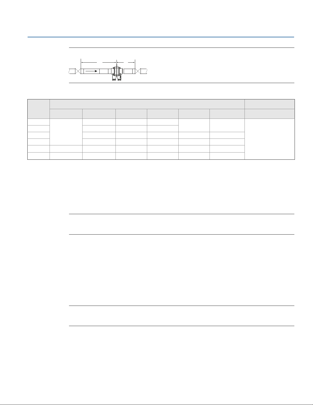
2.3.2 Straight run requirements
Figure 2-1. Reducer
U D
(2d to d over a length of 1.5d to 3d)
Figure 2-2. Single 90° Bend Flow from One Branch
U D
Figure 2-3. Two or More 90° Bends in Same Planes
U
D
(1)
Figure 2-4. Two or More 90° Bends in Different Planes
U D
Figure 2-5. Expander
(0.5d to d over a length of d to 2d)
1, For dimensions, see Table 1 on page 5.
4
U D
Installation
Reference Manual
00809-0100-4686, Rev KA
Figure 2-6. Ball/Gate Valve Fully Open
U D
Table 1. Straight Run Requirements (in Pipe Diameters)
Installation
December 2017
(1)
β
Upstream (U) Downstream (D)
Figure 2-1 Figure 2-2 Figure 2-3 Figure 2-4 Figure 2-5 Figure 2-6 Figures 3–8
0.20
0.40 25 27 31
0.50 25 28 33 23 23
0.60 27 31 37 25 25
0.70 23 32 35 42 28 28
0.75 25 35 38 45 30 30
Interpolation of intermediate β values can be used.
1.
2.
All straight lengths are expressed as multiples of the pipe inside diameter (d) and shall be measured from the upstream face of orifice plate.
20
24 25 30
22 22
2.3.3 Bolting a transmitter to the Rosemount 1195
If the Rosemount 1195 is ordered separately from the Rosemount transmitter and will be used in a direct
mount configuration, it will need to be assembled to the transmitter.
Follow the directions below to assemble the Rosemount 1195 to a transmitter with manifold:
Note
Units shipped from the factory direct mounted are pressure tested and characterized with the primary
attached. Factory assembly is recommended for best performance.
Bolt to a 3- or 5-valve manifold
(2)
10
Installation
1. Use studs and nuts supplied with the Rosemount1195 to connect to the transmitter sensor and
manifold.
2. Always use a 3- or 5-valve manifold when direct mounting a transmitter to the Rosemount 1195.
3. Observe the side of the orifice plate marked “Inlet.” This side should align to the High Pressure side of
the DP transmitter.
4. Torque the bolts to 32 lb-ft using a cross pattern.
Note
Protect the transmitter sensing diaphragms and do not remove the O-rings in transmitter sensor
module.
5. Carefully assemble the Rosemount 1195 body to the manifold and pressure transmitter sensor
making sure the “H” and “L” on transmitter and primary match.
6. Preload to 16 lb-ft then final torque at 32 lb-ft using a cross pattern.
5
 Loading...