

Rosemount 3051SFA, 3051CFA Operating Manual
Reference Manual
Rosemount 3051SFC_A
Compact Annubar
Flowmeter
Rosemount 3051SFA
Annubar Flowmeter
Rosemount 3051CFA
Annubar Flowmeter
Rosemount 2051CFA
Annubar Flowmeter
Rosemount 485
Annubar Primary
Element
Rosemount 585 Severe
Service Annubar Primary
Element
00809-0100-4809, Rev DA
September 2015
The Rosemount® Annubar® Flowmeter Series


Reference Manual
00809-0100-4809, Rev DA
Contents
1Section 1: Introduction
2Section 2: Installation
Contents
September 2015
1.1 Using this manual. . . . . . . . . . . . . . . . . . . . . . . . . . . . . . . . . . . . . . . . . . . . . . . . . . . . . . . 1
1.2 Product recycling/disposal . . . . . . . . . . . . . . . . . . . . . . . . . . . . . . . . . . . . . . . . . . . . . . .2
2.1 Safety messages. . . . . . . . . . . . . . . . . . . . . . . . . . . . . . . . . . . . . . . . . . . . . . . . . . . . . . . .3
2.2 Receiving and inspection . . . . . . . . . . . . . . . . . . . . . . . . . . . . . . . . . . . . . . . . . . . . . . . .3
2.3 Considerations . . . . . . . . . . . . . . . . . . . . . . . . . . . . . . . . . . . . . . . . . . . . . . . . . . . . . . . . .4
2.3.1 Limitations . . . . . . . . . . . . . . . . . . . . . . . . . . . . . . . . . . . . . . . . . . . . . . . . . . . . . . . 4
2.3.2 Environmental . . . . . . . . . . . . . . . . . . . . . . . . . . . . . . . . . . . . . . . . . . . . . . . . . . . .4
2.4 Installation flowchart and checklist . . . . . . . . . . . . . . . . . . . . . . . . . . . . . . . . . . . . . . .6
2.5 Mounting . . . . . . . . . . . . . . . . . . . . . . . . . . . . . . . . . . . . . . . . . . . . . . . . . . . . . . . . . . . . . .8
2.5.1 Tools and supplies . . . . . . . . . . . . . . . . . . . . . . . . . . . . . . . . . . . . . . . . . . . . . . . .8
2.5.2 Mounting brackets . . . . . . . . . . . . . . . . . . . . . . . . . . . . . . . . . . . . . . . . . . . . . . . .8
2.5.3 Bolt installation guidelines . . . . . . . . . . . . . . . . . . . . . . . . . . . . . . . . . . . . . . . . .8
2.5.4 Instrument manifolds . . . . . . . . . . . . . . . . . . . . . . . . . . . . . . . . . . . . . . . . . . . . .9
2.5.5 Straight run requirements. . . . . . . . . . . . . . . . . . . . . . . . . . . . . . . . . . . . . . . . .11
2.5.6 Flowmeter orientation . . . . . . . . . . . . . . . . . . . . . . . . . . . . . . . . . . . . . . . . . . . .14
2.5.7 Remote mounted transmitter . . . . . . . . . . . . . . . . . . . . . . . . . . . . . . . . . . . . .17
2.5.8 Flo-Tap models . . . . . . . . . . . . . . . . . . . . . . . . . . . . . . . . . . . . . . . . . . . . . . . . . .19
2.6 Installation. . . . . . . . . . . . . . . . . . . . . . . . . . . . . . . . . . . . . . . . . . . . . . . . . . . . . . . . . . . .22
2.6.1 Pak-Lok Annubar sensor type (for 485 Annubar Flowmeters) . . . . . . . . . .22
2.6.2 Flanged with opposite side support Annubar sensor type
(for 485 and 585 Annubar Flowmeters) . . . . . . . . . . . . . . . . . . . . . . . . . . . . .28
2.6.3 Flange-Lok model (for 485 Annubar Flowmeters) . . . . . . . . . . . . . . . . . . . .34
2.6.4 Threaded Flo-tap (for 485 Annubar Flowmeter) . . . . . . . . . . . . . . . . . . . . . .41
2.6.5 Flanged Flo-tap (for 485 and 585 Annubar Flowmeters). . . . . . . . . . . . . . .47
2.6.6 Main steam line (for 585 Annubar Flowmeters) . . . . . . . . . . . . . . . . . . . . . .55
2.7 Wire the transmitter . . . . . . . . . . . . . . . . . . . . . . . . . . . . . . . . . . . . . . . . . . . . . . . . . . .59
2.7.1 Wiring diagrams . . . . . . . . . . . . . . . . . . . . . . . . . . . . . . . . . . . . . . . . . . . . . . . . .59
Content s
iii

Contents
September 2015
Reference Manual
00809-0100-4809, Rev DA
3Section 3: Commissioning
3.1 Safety messages. . . . . . . . . . . . . . . . . . . . . . . . . . . . . . . . . . . . . . . . . . . . . . . . . . . . . . .61
3.2 Transmitter commissioning. . . . . . . . . . . . . . . . . . . . . . . . . . . . . . . . . . . . . . . . . . . . .62
3.3 Commissioning the Annubar sensor. . . . . . . . . . . . . . . . . . . . . . . . . . . . . . . . . . . . . .62
3.3.1 Direct mount transmitter . . . . . . . . . . . . . . . . . . . . . . . . . . . . . . . . . . . . . . . . .62
3.3.2 Remote mount transmitter. . . . . . . . . . . . . . . . . . . . . . . . . . . . . . . . . . . . . . . .68
4Section 4: Operation and Maintenance
4.1 Safety messages. . . . . . . . . . . . . . . . . . . . . . . . . . . . . . . . . . . . . . . . . . . . . . . . . . . . . . .75
4.2 RTD maintenance. . . . . . . . . . . . . . . . . . . . . . . . . . . . . . . . . . . . . . . . . . . . . . . . . . . . . .75
4.2.1 Replacing an RTD . . . . . . . . . . . . . . . . . . . . . . . . . . . . . . . . . . . . . . . . . . . . . . . .75
4.2.2 Electrical RTD check procedure . . . . . . . . . . . . . . . . . . . . . . . . . . . . . . . . . . . .78
4.3 Pak-Lok, Flange-Lok, and Flo-Tap maintenance . . . . . . . . . . . . . . . . . . . . . . . . . . . .79
4.4 Gas entrapment . . . . . . . . . . . . . . . . . . . . . . . . . . . . . . . . . . . . . . . . . . . . . . . . . . . . . . .80
4.5 Dirt accumulation . . . . . . . . . . . . . . . . . . . . . . . . . . . . . . . . . . . . . . . . . . . . . . . . . . . . .80
4.6 Main steam line Annubar sensor maintenance. . . . . . . . . . . . . . . . . . . . . . . . . . . . .81
5Section 5: Troubleshooting
5.1 Basic troubleshooting . . . . . . . . . . . . . . . . . . . . . . . . . . . . . . . . . . . . . . . . . . . . . . . . . .83
5.2 Return of materials . . . . . . . . . . . . . . . . . . . . . . . . . . . . . . . . . . . . . . . . . . . . . . . . . . . .85
AAppendix A: Specifications and Reference Data
A.1 3051SFA ordering information . . . . . . . . . . . . . . . . . . . . . . . . . . . . . . . . . . . . . . . . . .87
A.1.1 Rosemount® 3051SFA Annubar® Flowmeter . . . . . . . . . . . . . . . . . . . . . . .87
A.2 3051SFC ordering information . . . . . . . . . . . . . . . . . . . . . . . . . . . . . . . . . . . . . . . . 100
A.3 3051SF specifications . . . . . . . . . . . . . . . . . . . . . . . . . . . . . . . . . . . . . . . . . . . . . . . . 109
A.3.1 Performance specifications. . . . . . . . . . . . . . . . . . . . . . . . . . . . . . . . . . . . . . 109
A.3.2 Functional specifications. . . . . . . . . . . . . . . . . . . . . . . . . . . . . . . . . . . . . . . . 111
A.3.3 Physical specifications . . . . . . . . . . . . . . . . . . . . . . . . . . . . . . . . . . . . . . . . . . 116
A.4 3051CFA ordering information . . . . . . . . . . . . . . . . . . . . . . . . . . . . . . . . . . . . . . . . 117
A.4.1 Rosemount 3051CFA Annubar Flowmeter . . . . . . . . . . . . . . . . . . . . . . . . 117
A.5 3051CFC ordering information . . . . . . . . . . . . . . . . . . . . . . . . . . . . . . . . . . . . . . . . 126
A.5.1 Rosemount 3051CFC Compact Flowmeter . . . . . . . . . . . . . . . . . . . . . . . . 126
A.6 3051CF specifications . . . . . . . . . . . . . . . . . . . . . . . . . . . . . . . . . . . . . . . . . . . . . . . . 132
A.6.1 Performance specifications. . . . . . . . . . . . . . . . . . . . . . . . . . . . . . . . . . . . . . 132
A.6.2 Functional specifications. . . . . . . . . . . . . . . . . . . . . . . . . . . . . . . . . . . . . . . . 132
A.6.3 Physical specifications . . . . . . . . . . . . . . . . . . . . . . . . . . . . . . . . . . . . . . . . . . 135
A.7 2051CFA ordering information . . . . . . . . . . . . . . . . . . . . . . . . . . . . . . . . . . . . . . . . 136
iv
Content s

Reference Manual
00809-0100-4809, Rev DA
Contents
September 2015
A.8 2051CFC ordering information . . . . . . . . . . . . . . . . . . . . . . . . . . . . . . . . . . . . . . . . 143
A.8.1 Rosemount 2051CFC Compact Flowmeter . . . . . . . . . . . . . . . . . . . . . . . . 143
A.9 2051CF specifications . . . . . . . . . . . . . . . . . . . . . . . . . . . . . . . . . . . . . . . . . . . . . . . . 149
A.9.1 Performance specifications. . . . . . . . . . . . . . . . . . . . . . . . . . . . . . . . . . . . . . 149
A.9.2 Functional specifications. . . . . . . . . . . . . . . . . . . . . . . . . . . . . . . . . . . . . . . . 149
A.9.3 Physical specifications . . . . . . . . . . . . . . . . . . . . . . . . . . . . . . . . . . . . . . . . . . 154
A.10 485 Annubar primary element ordering information . . . . . . . . . . . . . . . . . . . . 155
A.11 485 specifications. . . . . . . . . . . . . . . . . . . . . . . . . . . . . . . . . . . . . . . . . . . . . . . . . . . 161
A.11.1 Performance specifications . . . . . . . . . . . . . . . . . . . . . . . . . . . . . . . . . . . . . 161
A.11.2 Functional specifications . . . . . . . . . . . . . . . . . . . . . . . . . . . . . . . . . . . . . . . 161
A.11.3 Physical specifications . . . . . . . . . . . . . . . . . . . . . . . . . . . . . . . . . . . . . . . . . 162
A.12 585 Annubar primary element ordering information . . . . . . . . . . . . . . . . . . . . 165
A.13 585 specifications. . . . . . . . . . . . . . . . . . . . . . . . . . . . . . . . . . . . . . . . . . . . . . . . . . . 170
A.13.1 Performance specifications . . . . . . . . . . . . . . . . . . . . . . . . . . . . . . . . . . . . . 170
A.13.2 Functional specifications . . . . . . . . . . . . . . . . . . . . . . . . . . . . . . . . . . . . . . . 170
A.13.3 Physical specifications . . . . . . . . . . . . . . . . . . . . . . . . . . . . . . . . . . . . . . . . . 171
A.14 405 Compact primary element ordering information. . . . . . . . . . . . . . . . . . . . 173
A.15 405 Specifications . . . . . . . . . . . . . . . . . . . . . . . . . . . . . . . . . . . . . . . . . . . . . . . . . . 176
A.15.1 Performance specifications . . . . . . . . . . . . . . . . . . . . . . . . . . . . . . . . . . . . . 176
A.15.2 Functional specifications . . . . . . . . . . . . . . . . . . . . . . . . . . . . . . . . . . . . . . . 176
A.15.3 Physical specifications . . . . . . . . . . . . . . . . . . . . . . . . . . . . . . . . . . . . . . . . . 177
A.16 Dimensional drawings. . . . . . . . . . . . . . . . . . . . . . . . . . . . . . . . . . . . . . . . . . . . . . . 178
A.16.1 3051SF dimensional drawings . . . . . . . . . . . . . . . . . . . . . . . . . . . . . . . . . . 178
A.16.2 3051CF dimensional drawings . . . . . . . . . . . . . . . . . . . . . . . . . . . . . . . . . . 187
A.16.3 2051CF dimensional drawings . . . . . . . . . . . . . . . . . . . . . . . . . . . . . . . . . . 196
A.16.4 485 dimensional drawings. . . . . . . . . . . . . . . . . . . . . . . . . . . . . . . . . . . . . . 200
A.16.5 585 dimensional drawings. . . . . . . . . . . . . . . . . . . . . . . . . . . . . . . . . . . . . . 208
A.16.6 405 Dimensional drawings . . . . . . . . . . . . . . . . . . . . . . . . . . . . . . . . . . . . . 212
BAppendix B: Product Certifications
B.1 Hazardous Locations Installations. . . . . . . . . . . . . . . . . . . . . . . . . . . . . . . . . . . . . . 213
B.2 Rosemount® 3051SFA and 3051SFC_A . . . . . . . . . . . . . . . . . . . . . . . . . . . . . . . . 213
B.2.1 European Directive Information. . . . . . . . . . . . . . . . . . . . . . . . . . . . . . . . . . 213
B.2.2 Ordinary Location Certification . . . . . . . . . . . . . . . . . . . . . . . . . . . . . . . . . . 213
Content s
B.2.3 Installing Equipment in North America. . . . . . . . . . . . . . . . . . . . . . . . . . . . 213
B.3 Rosemount 3051CFA and 3051CFC_A. . . . . . . . . . . . . . . . . . . . . . . . . . . . . . . . . . 218
B.3.1 European Directive Information. . . . . . . . . . . . . . . . . . . . . . . . . . . . . . . . . . 218
B.3.2 Ordinary Location Certification . . . . . . . . . . . . . . . . . . . . . . . . . . . . . . . . . . 218
v

Contents
September 2015
Reference Manual
00809-0100-4809, Rev DA
B.4 Rosemount 2051CFA and 2051CFC_A. . . . . . . . . . . . . . . . . . . . . . . . . . . . . . . . . . 224
B.4.1 European Directive Information. . . . . . . . . . . . . . . . . . . . . . . . . . . . . . . . . . 224
B.4.2 Ordinary Location Certification . . . . . . . . . . . . . . . . . . . . . . . . . . . . . . . . . . 224
B.5 Installation Drawings. . . . . . . . . . . . . . . . . . . . . . . . . . . . . . . . . . . . . . . . . . . . . . . . . 229
B.5.1 Rosemount 3051SFA ProBar Flowmeter . . . . . . . . . . . . . . . . . . . . . . . . . . 229
B.5.2 Rosemount 3051SFC_A Flowmeter . . . . . . . . . . . . . . . . . . . . . . . . . . . . . . 229
vi
Content s

Title Page
NOTICE
September 2015
Reference Manual
00809-0100-4809, Rev DA
The Rosemount® Annubar®
Flowmeter Series
Read this manual before working with the product. For personal and system safety, and for
optimum product performance, make sure you thoroughly understand the contents before
installing, using, or maintaining this product.
The United States has two toll-free assistance numbers and one International number.
Customer Central
1-800-999-9307 (7:00 A.M. to 7:00 P.M. CST)
International
1-(952) 906-8888
National Response Center
1-800-654-7768 (24 hours a day)
Equipment service needs
Explosions could result in death or serious injury.
Do not remove the transmitter cover in explosive atmospheres when the circuit is live.
Before connecting a Field Communicator in an explosive atmosphere, make sure the
instruments in the loop are installed in accordance with intrinsically safe or
non-incendive field wiring practices.
Verify the operating atmosphere of the transmitter is consistent with the appropriate
hazardous locations certifications.
Both transmitter covers must be fully engaged to meet explosion-proof requirements.
Failure to follow these installation guidelines could result in death or serious injury.
Make sure only qualified personnel perform the installation.
If the line is pressurized, serious injury or death could occur by opening valves.
Electrical shock can result in death or serious injury.
Avoid contact with the leads and the terminals.
vii

Title Page
September 2015
Reference Manual
00809-0100-4809, Rev DA
The products described in this document are NOT designed for nuclear-qualified
applications. Using non-nuclear qualified products in applications that require
nuclear-qualified hardware or products may cause inaccurate readings.
For information on Rosemount nuclear-qualified products, contact your local Emerson
™
Process Management Sales Representative.
This device is intended for use in temperature monitoring applications and should not be
used in control and safety applications.
If pipe/duct wall is less than 0.125-in. (3.2mm) use extreme caution when installing sensor.
Thin walls can deform during welding, installation, or from the weight of a cantilevered
flowmeter. These installations may require a fabricated outlet, saddle, or external
flowmeter support. Consult factory for assistance.
viii

Reference Manual
00809-0100-4809, Rev DA
Section 1 Introduction
1.1 Using this manual
This product manual provides installation, configuration, calibration, troubleshooting, and
maintenance instructions for the Rosemount
®
Annubar® Flowmeter Series.
Section 1: Introduction
September 2015
Section 2: Installation
Installation flowchart and checklist
Orienting, mounting, and installing the flowmeter
Connecting the Wiring
Section 3: Commissioning
Calibrating the flowmeter
Section 4: Operation and Maintenance
Troubleshooting information
Disassembly
RTD maintenance
Appendix A: Specifications and Reference Data
Specifications
Dimensional drawings
Appendix B: Product Certifications
Approvals certifications
Installation drawings
Introduction
Information in this manual applies to circular pipes only. Consult Rosemount Customer Central
for instructions regarding use in square or rectangular ducts.
1

Section 1: Introduction
September 2015
1.2 Product recycling/disposal
Recycling of equipment and packaging should be taken into consideration and disposed of in
accordance with local and national legislation/regulations.
Reference Manual
00809-0100-4809, Rev DA
2
Introduction
Reference Manual
00809-0100-4809, Rev DA
Section 2 Installation
Safety messages . . . . . . . . . . . . . . . . . . . . . . . . . . . . . . . . . . . . . . . . . . . . . . . . . . . . . . . . . . . . page 3
Receiving and inspection . . . . . . . . . . . . . . . . . . . . . . . . . . . . . . . . . . . . . . . . . . . . . . . . . . . . page 3
Considerations . . . . . . . . . . . . . . . . . . . . . . . . . . . . . . . . . . . . . . . . . . . . . . . . . . . . . . . . . . . . . page 4
Installation flowchart and checklist . . . . . . . . . . . . . . . . . . . . . . . . . . . . . . . . . . . . . . . . . . . . page 6
Mounting . . . . . . . . . . . . . . . . . . . . . . . . . . . . . . . . . . . . . . . . . . . . . . . . . . . . . . . . . . . . . . . . . . page 8
Installation . . . . . . . . . . . . . . . . . . . . . . . . . . . . . . . . . . . . . . . . . . . . . . . . . . . . . . . . . . . . . . . . . page 22
Wire the transmitter . . . . . . . . . . . . . . . . . . . . . . . . . . . . . . . . . . . . . . . . . . . . . . . . . . . . . . . . page 59
2.1 Safety messages
Instructions and procedures in this section may require special precautions to ensure the safety
of the personnel performing the operations. Refer to the following safety messages before
performing any operation in this section.
Section 2: Installation
September 2015
If pipe/duct wall is less than 0.125-in. (3.2mm) use extreme caution when installing sensor.
Thin walls can deform during welding, installation, or from the weight of a cantilevered
flowmeter. These installations may require a fabricated outlet, saddle, or external
flowmeter support. Consult factory for assistance.
Explosions could result in death or serious injury.
Do not remove the transmitter cover in explosive atmospheres when the circuit is live.
Before connecting a Field Communicator in an explosive atmosphere, make sure the
instruments in the loop are installed in accordance with intrinsically safe or
non-incendive field wiring practices.
Verify the operating atmosphere of the transmitter is consistent with the appropriate
hazardous locations certifications.
Both transmitter covers must be fully engaged to meet explosion-proof requirements.
Failure to follow these installation guidelines could result in death or serious injury.
Make sure only qualified personnel perform the installation.
2.2 Receiving and inspection
Flowmeters are available in different models and with different options, so it is important to
inspect and verify that the appropriate model was delivered before installation.
Upon receipt of the shipment, check the packing list against the material received and the
purchase order. All items are tagged with a sales order number, serial number, and customer tag
number. Report any damage to the carrier.
3Installation
Section 2: Installation
September 2015
2.3 Considerations
2.3.1 Limitations
Structural
Structural limitations are printed on the sensor tag. Exceeding structural limitations may cause
sensor failure.
Functional
The most accurate and repeatable flow measurement occurs in the following conditions:
The structural limit differential pressure, as printed on the sensor tag, is not exceeded.
The instrument is not used for two-phase flow or for steam service below saturation
temperature.
Install the flowmeter in the correct location within the piping branch to prevent
measurement inaccuracies caused by flow disturbances.
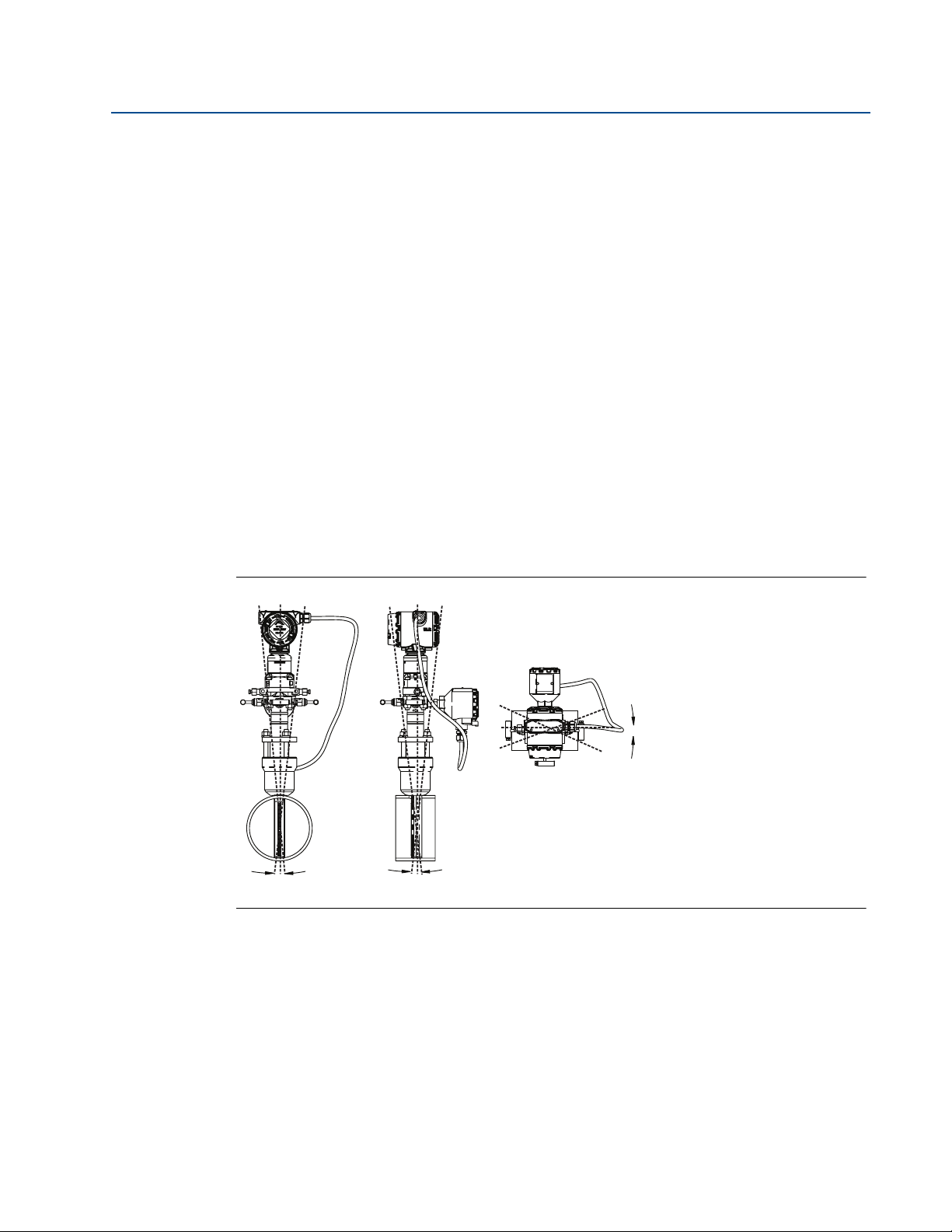
The flowmeter can be installed with a maximum misalignment of 3 degrees (see Figure
2-1). Misalignment beyond 3 degrees will cause flow measurement errors.
Reference Manual
00809-0100-4809, Rev DA
Figure 2-1. Permissible Misalignment
3° max. 3° max.
2.3.2 Environmental
Mount the flowmeter in a location with minimal ambient temperature changes. Appendix A:
Specifications and Reference Data lists the temperature operating limits. Mount to avoid
vibration, mechanical shock, and external contact with corrosive materials.
3° max.
Access requirements
Consider the need to access the flowmeter when choosing an installation location and
orientation.
4
Installation
Reference Manual
00809-0100-4809, Rev DA
Process flange orientation
Orient the process flanges on a remote mounted flowmeter so that process connections can be
made. For safety reasons, orient the drain/vent valves so that process fluid is directed away from
technicians when the valves are used. In addition, consider the possible need for a testing or
calibration input.
Housing rotation
The electronics housing may be rotated up to 180 degrees (left or right) to improve field access
to the two compartments or to better view the optional LCD meter. To rotate the housing,
release the housing rotation set screw and turn the housing up to 180 degrees.
Electronics housing
Terminal side
The circuit compartment should not routinely need to be opened when the unit is in service.
Wiring connections are made through the conduit openings on the top or side of the housing.
The field terminal side is marked on the electronics housing. Mount the flowmeter so that the
terminal side is accessible. A 0.75-in. (19 mm) clearance is required for cover removal. Use a
conduit plug on the unused side of the conduit opening. A 3-in. (76 mm) clearance is required
for cover removal if a meter is installed.
Section 2: Installation
September 2015
Cover installations
Always install the electronics housing covers metal-to-metal to ensure a proper seal.
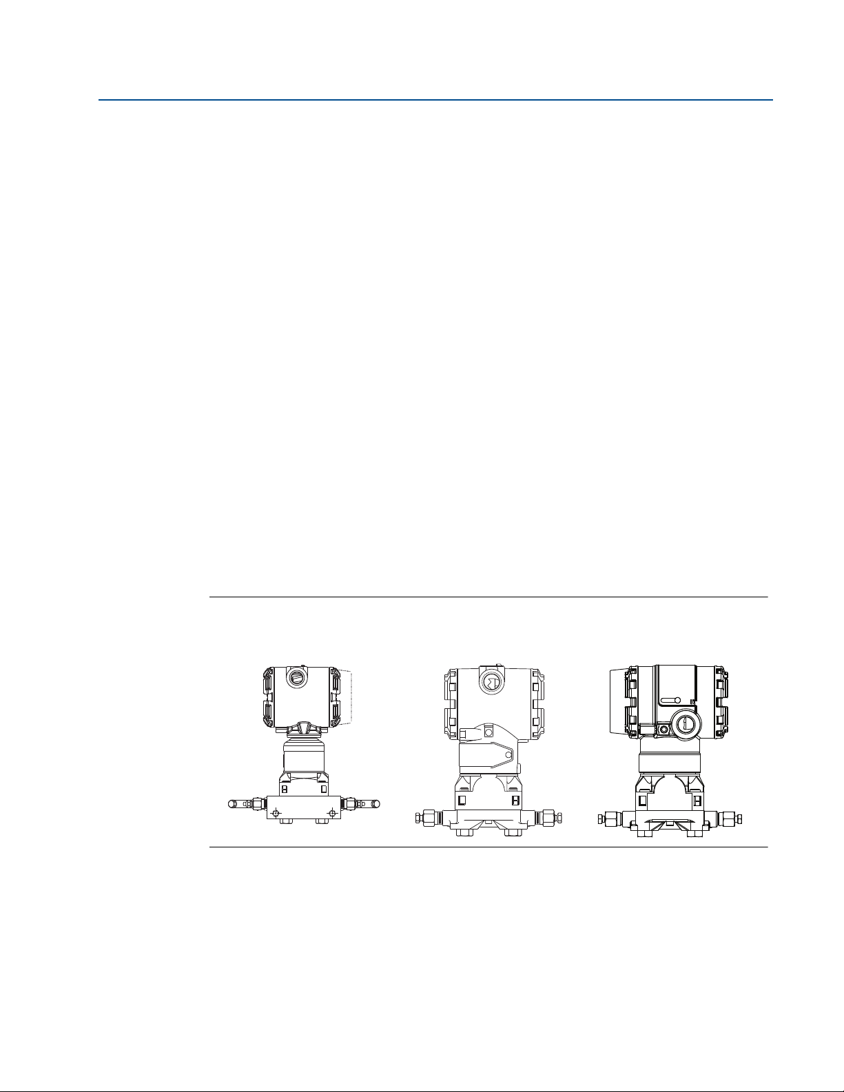
Figure 2-2. Transmitter Housing
Rosemount® 3051S
MultiVariable
™
Transmitter
Rosemount 3051C
Tra ns mitt er
Rosemount 2051C
Tra ns mitt er
Installation
5
Section 2: Installation
September 2015
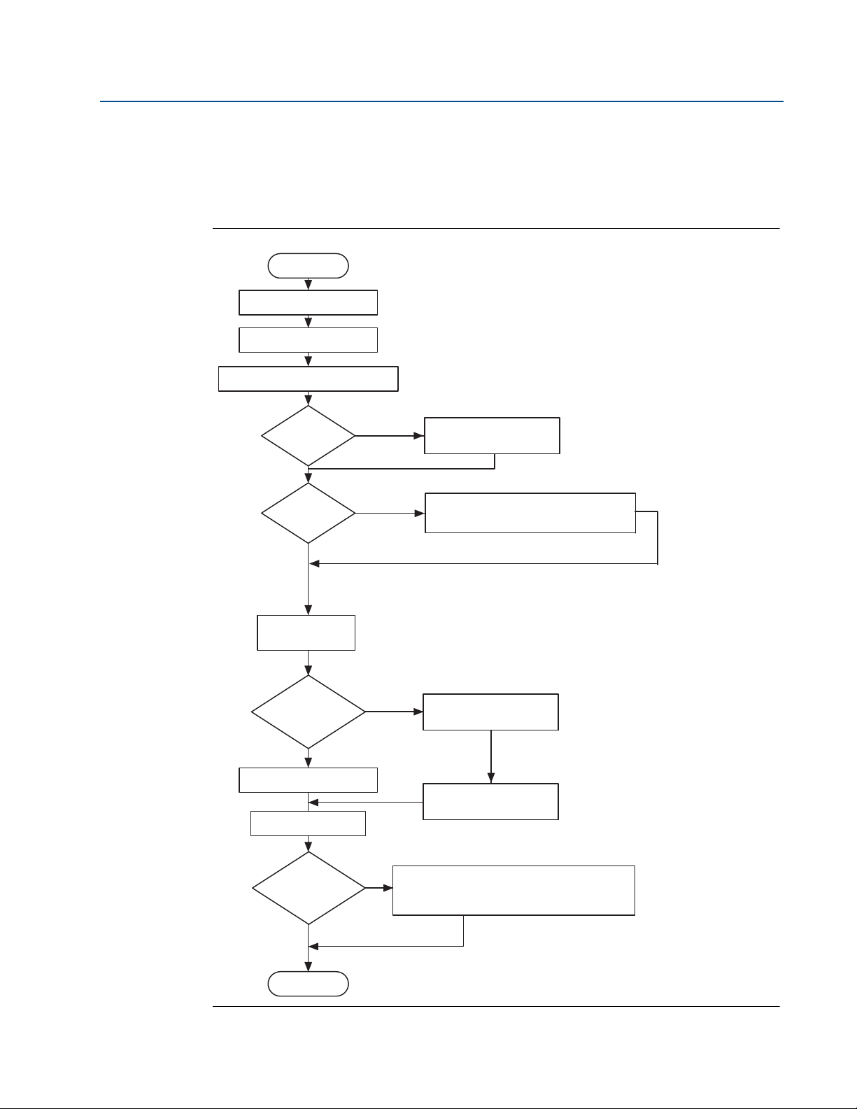
2.4 Installation flowchart and checklist
Figure 2-3 is an installation flowchart that provides guidance through the installation process.
Following the figure, an installation checklist has been provided to verify that all critical steps
have been taken in the installation process. The checklist numbers are indicated in the
flowchart.
Figure 2-3. Installation Chart
Start
Unpack instrument
Review product manual
Verify proper installation location Steps 1, 2
Reference Manual
00809-0100-4809, Rev DA
Step 4
Step 5-9
Hazardous
location?
No
Bench
configure?
No
Verify model
indicated on tag
Remote
mounted
transmitter
No
Install flowmeter
Wire
Yes
Yes
Yes
Review Appendix B
See appropriate transmitter manual
for bench configuration information
Install hardware
Install transmitter
Step 3
Remote
mounted
electronics?
No
Finish
6
Step 11-14
Commission the transmitter. See appropriate
transmitter manual for bench configuration
information.
Installation

Reference Manual
00809-0100-4809, Rev DA
The following is a summary of the steps required to complete a flowmeter installation. If this is a
new installation, begin with Step 1. If the mounting is already in place, verify the hole size and
fittings match the recommended specifications (see Table 2-3 on page 23) and begin with Step
5.
1. Determine where the flowmeter is to be placed within the piping system.
2. Establish the proper orientation as determined by the intended application.
3. Review Appendix B: Product Certifications and determine if the flowmeter is located in
4. Confirm the configuration.
5. Drill the correct sized hole into the pipe and deburr. Do not torch-cut holes. If installing
6. For instruments equipped with opposite-side support, drill a second hole 180° from the
Section 2: Installation
September 2015
a hazardous location.
a wafer-style Annubar flowmeter, place the flowmeter between raised-face flanges,
utilizing the centering ring to install the flowmeter, and skip to Step 11.
first hole.
7. Weld the mounting per plant welding procedures.
8. Measure the pipe’s internal diameter (ID), preferably at 1 ⫻ ID from the hole (upstream
or downstream).
Note
To maintain published flowmeter accuracy, provide the pipe ID when purchasing the flowmeter.
9. Check the set-up of the instrument assembly to the pipe.
10. Install the flowmeter.
11. Wire the instrument.
12. Supply power to the flowmeter.
13. Perform a trim for mounting effects.
14. Check for leaks.
15. Commission the instrument.
Installation
7

Section 2: Installation
September 2015
2.5 Mounting
2.5.1 Tools and supplies
Tools required include the following:
Open end or combination wrenches (spanners) to fit the pipe fittings and bolts:
Adjustable wrench: 15-in. (1
Nut driver:
#1 Phillip’s screwdriver
Standard screwdrivers:
14-in. Pipe wrench
Wire cutters/strippers
Supplies required include the following:
Fittings including (but not limited to)
5
/8-in., and 7/8-in
3
/8-in. for vent/drain valves (or 3/8-in. wrench)
7
/16-in. box wrench (required for the ferry head bolt design)
1
/2-in. tubing or 1/2-in. pipe (recommended) to hook up the electronics to the sensor
probe. The length required depends upon the distance between the electronics and the
sensor
1
/2-in. jaw)
1
/4-in. and 1/8-in. wide
Reference Manual
00809-0100-4809, Rev DA
9
/16-in.,
– Two tube or pipe tees (for steam or high temperature liquid) and
– Six tube/pipe fittings (for tube)
Pipe compound or PTFE tape (where local piping codes allow)
2.5.2 Mounting brackets
Mounting brackets are provided with any flowmeter order with a remote mounted transmitter to
facilitate mounting to a panel, wall, or 2-in. (50.8 mm) pipe. The bracket option for use with the
Coplanar flange is 316 SST with 316 SST bolts.
When installing the transmitter to one of the mounting brackets, torque the bolts to 125 in-lb.
(169 N-m).
2.5.3 Bolt installation guidelines
The following guidelines have been established to ensure a tight flange, adapter, or manifold
seal. Only use bolts supplied with the instrument or sold by the factory.
The instrument is shipped with the coplanar flange installed with four 1.75-in. (44.5 mm) flange
bolts. The following bolts also are supplied to facilitate other mounting configurations:
Four 2.25-in. (57.2 mm) manifold/flange bolts for mounting the coplanar flange on a
three-valve manifold. In this configuration, the 1.75-in. (44.5 mm) bolts may be used to
mount the flange adapters to the process connection side of the manifold.
(Optional) If flange adapters are ordered, four 2.88-in. (73.2 mm) flange/adapter bolts
for mounting the flange adapters to the coplanar flange.
8
Installation
Reference Manual
B7M
316
316
®
B8M
STM
316
316
SW
316
2.25 (57) × 4
1.75 (44) × 4
00809-0100-4809, Rev DA
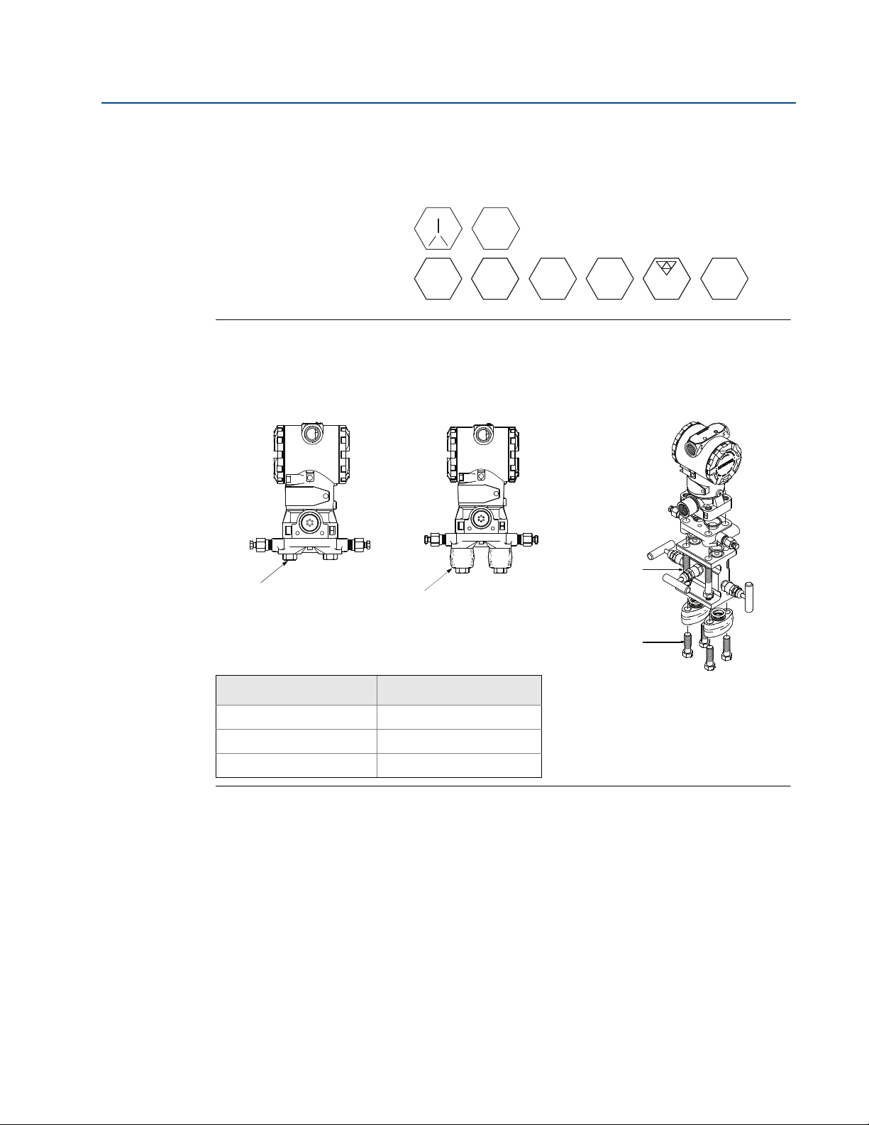
Stainless steel bolts supplied by Rosemount Inc. are coated with a lubricant to ease installation.
Carbon steel bolts do not require lubrication. Do not apply additional lubricant when installing
either type of bolt. Bolts supplied by Rosemount Inc. are identified by the following head
markings:
Figure 2-4. Coplanar Mounting Bolts and Bolting Configurations for Coplanar Flange
Carbon Steel Head Markings
(CS)
Stainless Steel Head Markings
(SST)
Transmitter with
flange bolts
Transmitter with
optional flange adapters
and flange/adapter bolts
Section 2: Installation
September 2015
Transmitter with 3-valve manifold,
manifold/flange bolts,
flange adapters, and
flange/adapter bolts
1.75 (44) × 4
2.88 (73) × 4
Description Size in. (mm)
Flange bolts (4) 1.75-in. (44 mm)
Flange/adapter bolts (4) 2.88-in. (73 mm)
Manifold/flange bolts (4) 2.25-in. (57 mm)
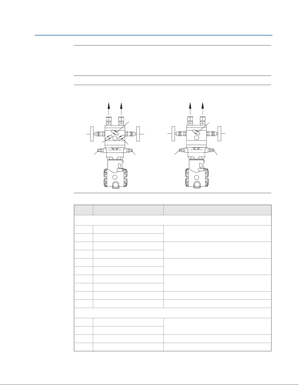
2.5.4 Instrument manifolds
Figure 2-5 on page 10 identifies the valves on a 5-valve and a 3-valve manifold. Table 2-1 on
page 10 explains the purpose of these valves.
An instrument manifold is recommended for all installations. A manifold allows an operator to
equalize the pressures prior to the zero calibration of the transmitter as well as to isolate the
electronics from the rest of the system without disconnecting the impulse piping. Although a
3-valve manifold can be used, a 5-valve manifold is recommended.
5-valve manifolds provide a positive method of indicating a partially closed or faulty equalizer
valve. A closed faulty equalizer valve will block the DP signal and create errors that may not be
detectable otherwise. The labels for each valve will be used to identify the proper valve in the
procedures to follow.
Installation
9
Section 2: Installation
To PH To PL
MV
ML
MEL
DVL
MH
MEH
DVH
2
1
To PL
ME
To PH
MH
DVH
ML
DVL
2
1
September 2015
Note
Some recently-designed instrument manifolds have a single valve actuator, but cannot perform
all of the functions available on standard 5-valve units. Check with the manufacturer to verify
the functions that a particular manifold can perform. In place of a manifold, individual valves
may be arranged to provide the necessary isolation and equalization functions.
Figure 2-5. Valve Identification for 5-Valve and 3-Valve Manifolds
Reference Manual
00809-0100-4809, Rev DA
5-valve manifold 3-valve manifold
Table 2-1. Description of Impulse Valves and Components
Name Description Purpose
Manifold and impulse pipe valves
PH Primary Sensor – High Pressure
PL Primary Sensor – Low Pressure
DVH Drain/Vent Valve – High Pressure
DVL Drain/Vent Valve – Low Pressure
MH Manifold – High Pressure
ML Manifold – Low Pressure
MEH Manifold Equalizer – High Pressure
MEL Manifold Equalizer – Low Pressure
ME Manifold Equalizer Allows high and low side pressure to equalize
MV Manifold Vent Valve Vents process fluid
Isolates the flowmeter sensor from the impulse piping
system
Drains (for gas service) or vents (for liquid or steam
service) the DP electronics chambers
Isolates high side or low side pressure from the
process.
Allows high and low pressure side access to the vent
valve, or for isolating the process fluid
Components
1 Tr an sm i tt er
2 Manifold
3 Vent Chambers Collects gases in liquid applications.
4 Condensate Chamber Collects condensate in gas applications.
Reads Differential Pressure
Isolates and equalizes transmitter
10
Installation

Reference Manual
00809-0100-4809, Rev DA
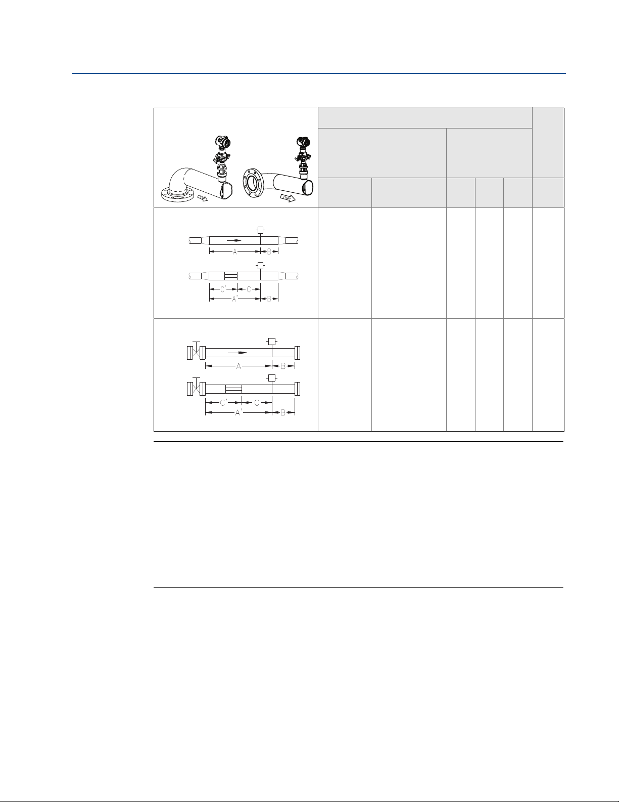
2.5.5 Straight run requirements
Use the following to aid in determining the straight run requirements.
Table 2-2. Straight Run Requirements
Section 2: Installation
September 2015
In plane Out of plane
Single elbow
1
Single elbow with straightening vanes
Double elbows in plane
2
Upstream dimensions
Without straightening
vanes
With
straightening
vanes
In plane A Out of plane A A’ C C’ B
8
N/A
11
N/A
10
N/A
16
N/A
N/A8N/A4N/A44
N/A8N/A4N/A44
dimensions
Downstream
4
4
Installation
Double elbow in plane with straightening
Double elbows out of plane
3
Double elbows out of plane with
4
Reducer with straightening vanes
vanes
straightening vanes
Reducer
23
N/A
12
N/A
28
N/A
12
N/A
N/A8N/A4N/A44
4
N/A8N/A4N/A44
4
11
Section 2: Installation
September 2015
Table 2-2. Straight Run Requirements
Reference Manual
00809-0100-4809, Rev DA
In plane Out of plane
Expander
5
Expander with straightening Vanes
Valv e
6
Upstream dimensions
Without straightening
vanes
With
straightening
vanes
In plane A Out of plane A A’ C C’ B
18
N/A
30
N/A
18
N/A
30
N/A
N/A8N/A4N/A44
N/A8N/A4N/A44
dimensions
Downstream
4
4
Valve with straightening Vanes
Note
If proper lengths of straight run are not available, position the mounting such that 80%
of the run is upstream and 20% is downstream.
“In Plane A” means the sensor is in the same plane as the elbow. “Out of Plane A” means
the sensor is perpendicular to the plane of the elbow.
The information contained in this manual is applicable to circular pipes only. Consult
the factory for instructions regarding use in square or rectangular ducts.
Straightening vanes may be used to reduce the required straight run length.
The last row in Tab l e 2- 2 applies to gate, globe, plug, and other throttling valves that are
partially opened, as well as control valves.
12
Installation

Reference Manual
00809-0100-4809, Rev DA
Figure 2-6. Mounting Configuration
Section 2: Installation
September 2015
Integral mount Remote mount
C
C
B
A
A. Annubar sensor
B. Mounting hardware (Annubar type)
A
C. Transmitter
B
Note
The direct-mounted flowmeter is usually shipped with the transmitter assembled to the sensor,
unless it is ordered with a Remote-mount Transmitter Connection Platform.
Installation
13
Section 2: Installation
Flow
360°
Note: Downward flow is not recommended.
September 2015
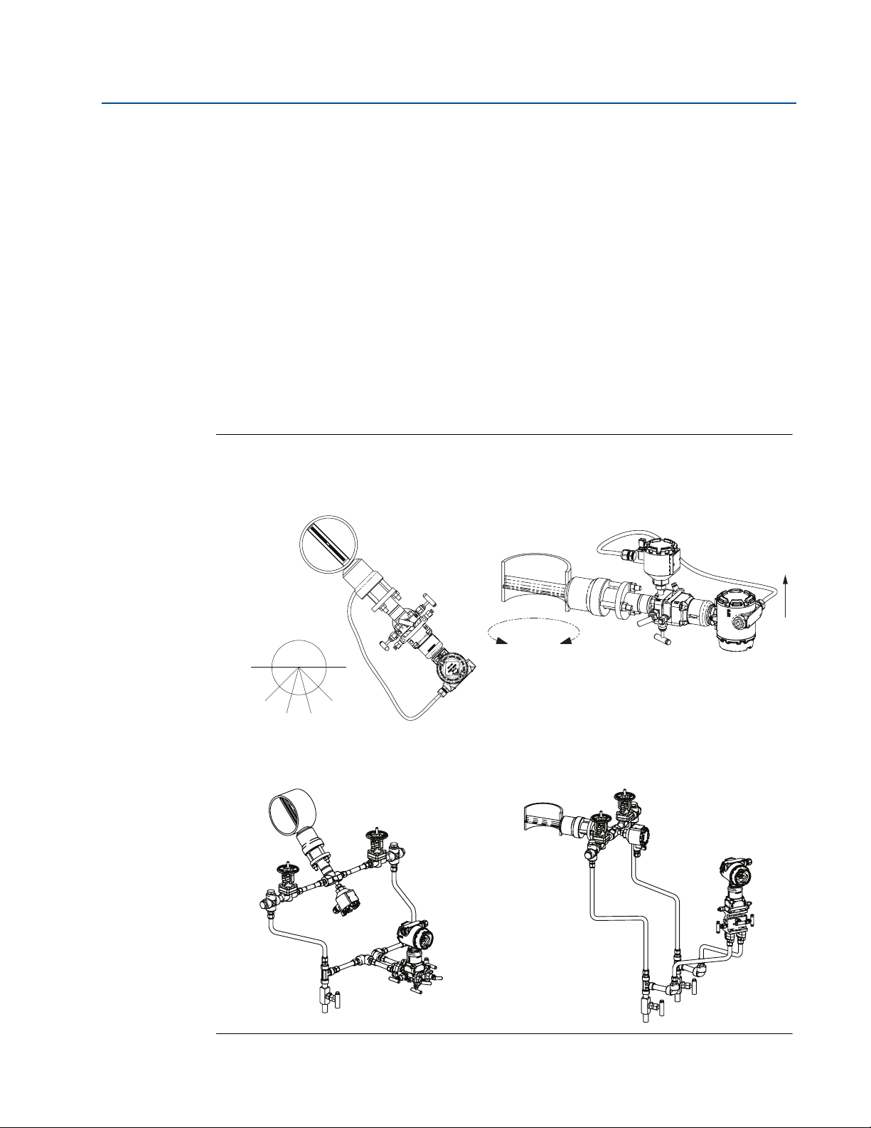
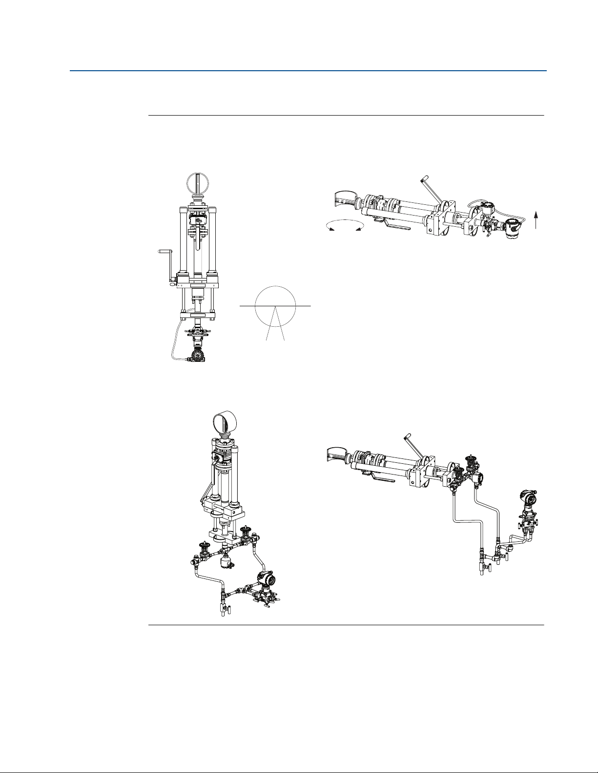
2.5.6 Flowmeter orientation
Liquid
Due to the possibility of air getting trapped in the Annubar sensor, it should be located
according to Figure 2-7 for liquid applications. It should be mounted between 15° to 45° from
vertical down to ensure that air is vented from the Annubar sensor, and that sediment or solid
particles are not collected within the Annubar sensor.
For liquid applications, mount the side drain/vent valve upward to allow the gases to vent. In
vertical lines, the Annubar sensor can be installed in any position around the circumference of
the pipe, provided the vents are positioned properly for bleeding or venting. Vertical pipe
installations require more frequent bleeding or venting, depending on the location.
For a remote mounted transmitter, mount the transmitter below the process piping, adjust 10°
to 15° above direct vertical down. Route the impulse piping down to the transmitter and fill the
system with cool water through the two cross fittings.
Figure 2-7. Liquid Applications
Reference Manual
00809-0100-4809, Rev DA
Direct mount
45° 45°
Recommended
zone 30°
Horizontal liquid Vertical liquid
Recommended
30°
zone 30°
Remote mount
Horizontal liquid Vertical liquid
14
Installation
Reference Manual
45° 45°
Recommended
zone 90°
00809-0100-4809, Rev DA
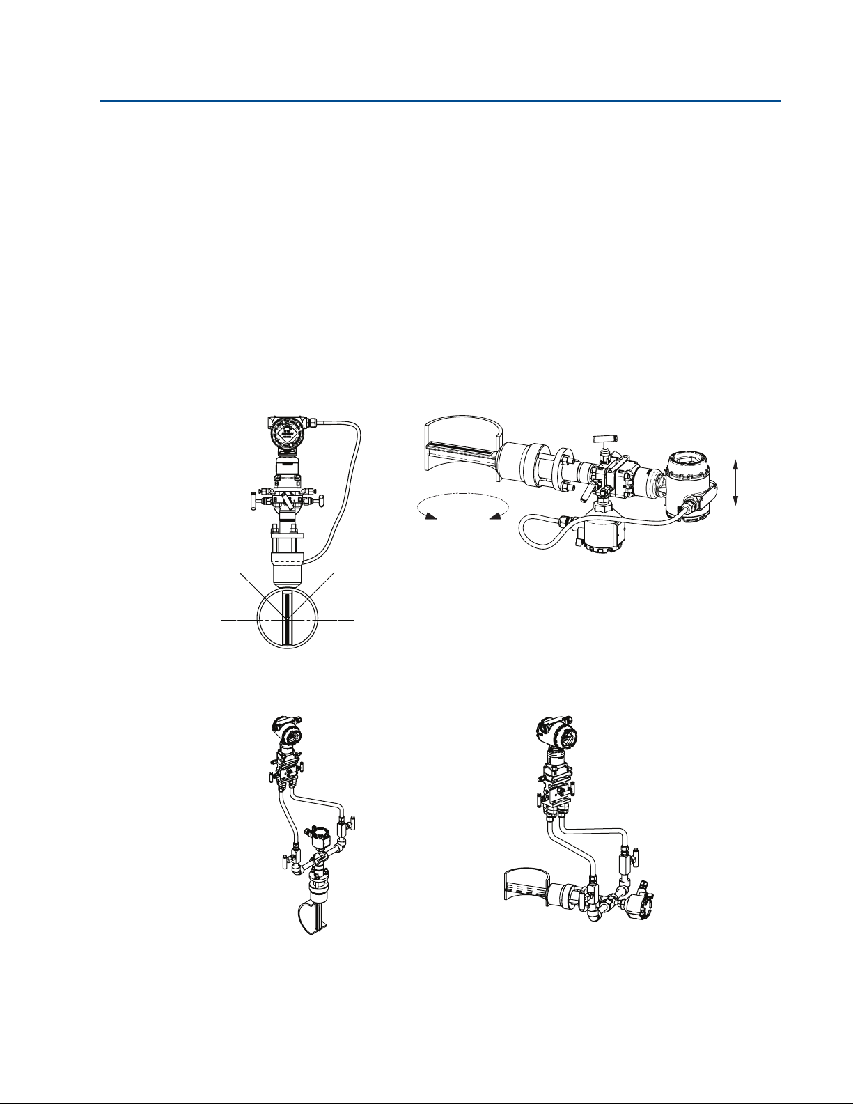
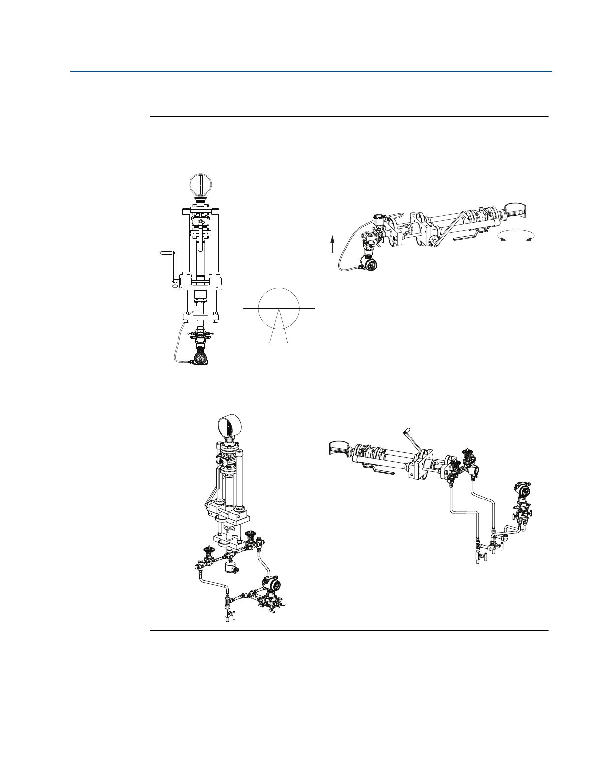
Gas
Figure 2-8 illustrates the recommended location of the flowmeter in gas applications. The
sensor should be located on the upper half of the pipe, at least 45° above the horizontal line.
For gas applications, mount the drain/vent valve downward to allow liquid to drain. In vertical
lines, the Annubar sensor can be installed in any position around the circumference of the pipe,
provided the vents are positioned properly for bleeding or venting. Vertical pipe installations
require more frequent bleeding or venting, depending on the location.
For a remote mounted transmitter, secure the transmitter above the Annubar sensor to prevent
condensible liquids from collecting in the impulse piping and the DP cell.
Figure 2-8. Gas Applications
Section 2: Installation
September 2015
Direct mount
Horizontal gas Vertical gas
360°
Remote mount
Horizontal gas Vertical gas
Flow
Installation
15

Section 2: Installation
45° 45°
30°
Recommended
zone 30°
Recommended
zone 30°
September 2015
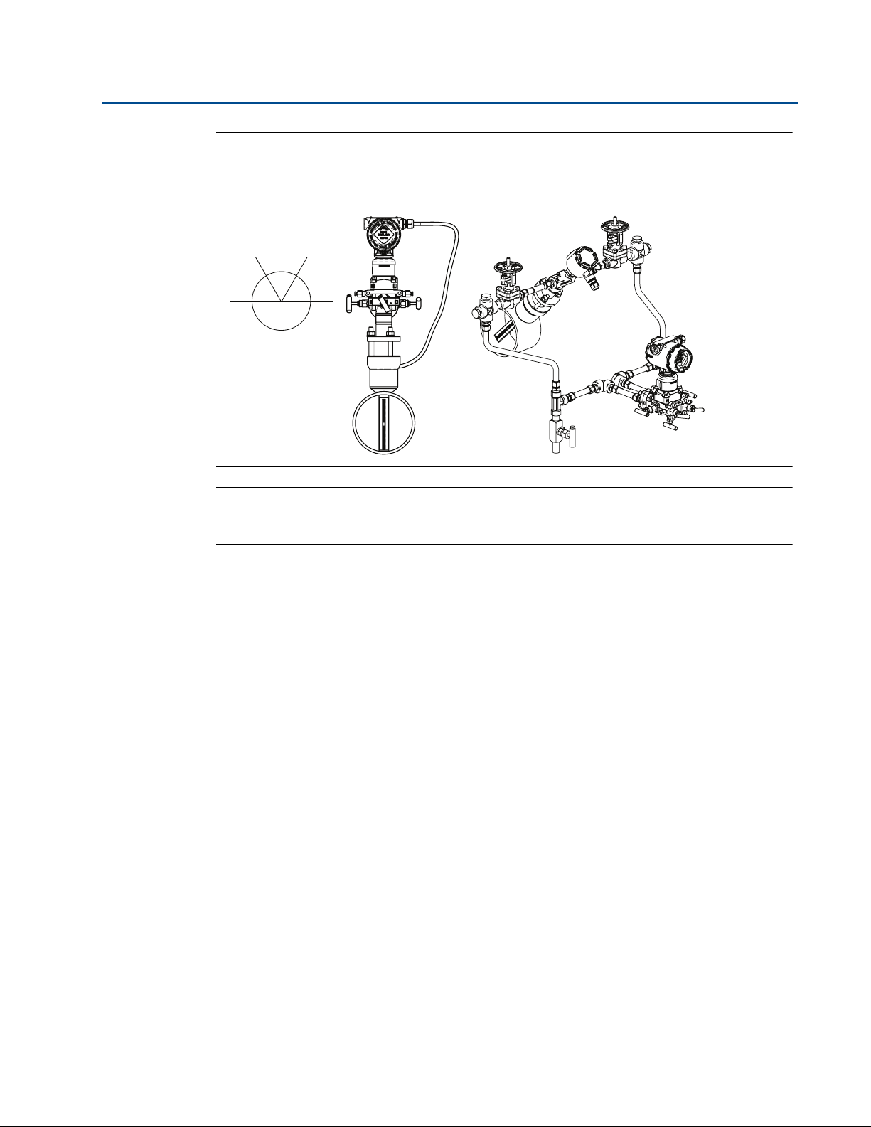
Steam
In steam applications, fill the lines with water to prevent the steam from contacting the
transmitter. Condensate chambers are not required because the volumetric displacement of the
transmitter is negligible.
For a remote mounted transmitter, mount the transmitter below the process piping, adjust to
10° to 15° above direct vertical down. Route the impulse piping down to the transmitter and fill
the system with cool water through the two cross fittings.
Top mounting for steam applications is an appropriate mounting option in many cases. Consult
Rosemount Customer Central for instructions regarding steam on top mounting.
Figure 2-9 illustrates the recommended location of the flowmeter in steam applications.
Figure 2-9. Steam Applications
Reference Manual
00809-0100-4809, Rev DA
Direct mount
Horizontal steam Vertical steam
Flow
Note: Downward flow is not recommended.
Remote mount
Horizontal steam Vertical steam
360°
16
Installation
Reference Manual
00809-0100-4809, Rev DA
Section 2: Installation
September 2015
Figure 2-10. Top Mounting for Steam
(1)
Direct mount Remote mount
Horizontal top mounting for steam
Recommended zone
60° 60°
60°
Note
For wet steam, do not mount the flowmeter at the direct vertical position. Mounting at an angle
will avoid measurement inaccuracy due to water running along the bottom of the pipe.
2.5.7 Remote mounted transmitter
Instrument head connections differ between horizontal and vertical pipes. For horizontal lines,
the instrument connections are parallel to the pipe and for vertical lines, the instrument
connection are perpendicular.
Valves and fittings
Throughout the remote mounting process:
Use only valves, fittings, and pipe thread sealant compounds that are rated for the
service pipeline design pressure and temperature as specified in Appendix A:
Specifications and Reference Data.
Verify that all connections are tight and that all instrument valves are fully closed.
Verify that the Annubar sensor is properly oriented for the intended type of service:
liquid, gas, or steam (see “Flowmeter orientation” on page 14).
Impulse piping
Impulse piping connects a remote mounted transmitter to the Annubar sensor. Temperatures in
excess of 250 °F (121 °C) at the transmitter will damage electronic components; impulse piping
allows service flow temperatures to decrease to a point where the transmitter is no longer
vulnerable.
1. Consult with RCC to determine if this installation is right for your application.
Installation
17

Section 2: Installation
September 2015
The following restrictions and recommendations apply to impulse piping location.
Piping used to connect the Annubar sensor and transmitter must be rated for
Impulse piping that runs horizontally must slope at least 1-in. per foot (83 mm/m).
With the Annubar mounted below the pipe, impulse piping must slope downwards
With the Annubar sensor mounted above the pipe, impulse piping must slope up
For applications where the pipeline temperature is below 250 °F (121 °C), the impulse
For applications where pipeline temperature is above 250 °F (121 °C), the impulse
A minimum of
Outdoor installations for liquid, saturated gas, or steam service may require insulation
Reference Manual
00809-0100-4809, Rev DA
continuous operation at the pipeline-designed pressure and temperature.
(toward the transmitter) for liquid and steam applications.
(toward from the transmitter) for gas applications.
piping should be as short as possible to minimize flow temperature changes. Insulation
may be required.
piping should have a minimum length of 1-ft. (0.30 m) for every 100 °F (38 °C) over
250 °F (121 °C), which is the maximum operating transmitter temperature. Impulse
piping must be uninsulated to reduce fluid temperature. All threaded connections
should be checked after the system comes up to temperature, because connections
may be loosened by the expansion and contraction caused by temperature changes.
1
/2-in. (12mm) outer diameter (OD) stainless steel tubing with a wall
thickness of at least 0.035-in. is recommended.
and heat tracing to prevent freezing.
For installations where the transmitter is more than 6-ft. (1.8m) from the Annubar
sensor, the high and low impulse piping must be run together to maintain equal
temperature. They must be supported to prevent sagging and vibration.
Threaded pipe fittings are not recommended because they create voids where air can
become entrapped and have more possibilities for leakage.
Run impulse piping in protected areas or against walls or ceilings. If the impulse piping
is run across the floor, ensure that it is protected with coverings or kick plates. Do not
locate the impulse piping near high temperature piping or equipment.
Use an appropriate pipe sealing compound rated for the service temperature on all
threaded connections. When making threaded connections between stainless steel
fittings, Loctite
®
PST® Sealant is recommended.
18
Installation
Reference Manual
00809-0100-4809, Rev DA
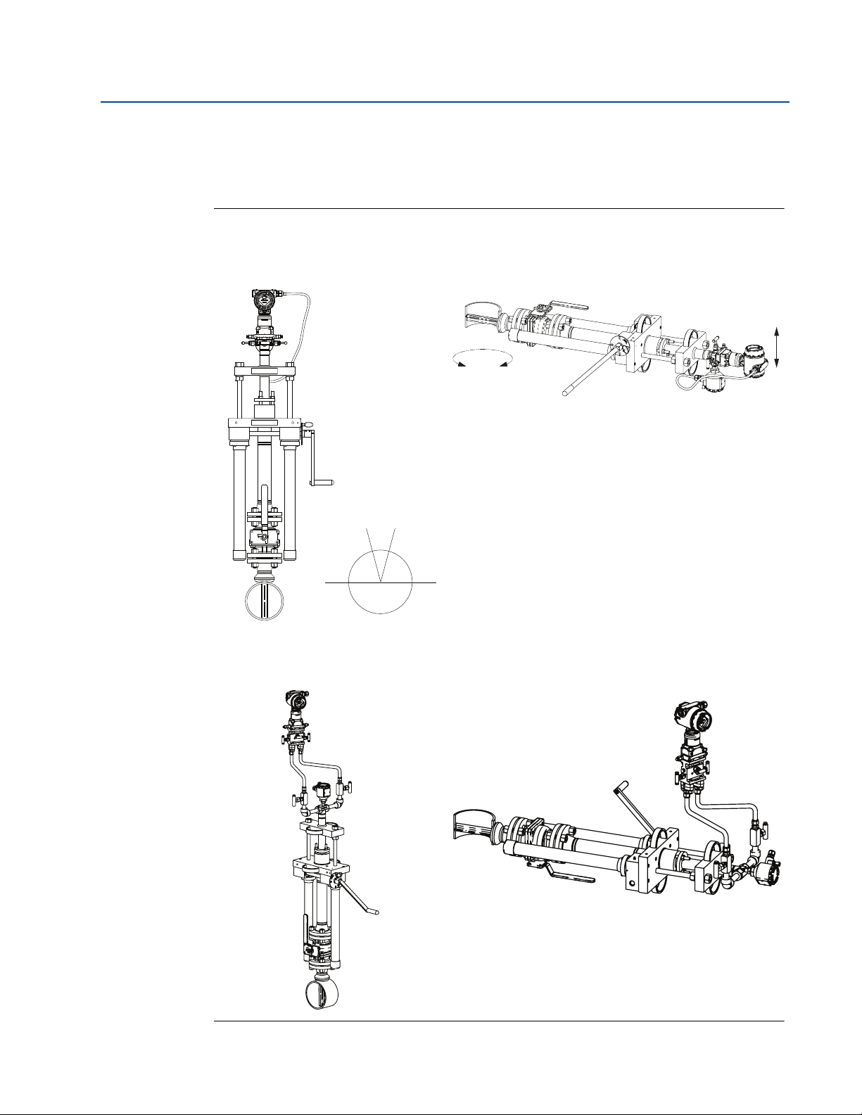
2.5.8 Flo-Tap models
Gas
Figure 2-11. Gas Service
Horizontal gas Vertical gas
Section 2: Installation
September 2015
Direct mount
360°
Flow
Recommended zone
30°
Remote mount
Horizontal gas Vertical gas
Installation
19
Section 2: Installation
360°
Flow
Note: Downward flow is not recommended.
September 2015
Liquid
Figure 2-12. Liquid Service
Reference Manual
00809-0100-4809, Rev DA
Direct mount
Horizontal liquid Vertical liquid
30°
Recommended zone
Remote mount
Horizontal liquid Vertical liquid
20
Installation
Reference Manual
360°
Flow
Note: Downward flow is not recommended.
00809-0100-4809, Rev DA
Steam
Figure 2-13. Steam
Section 2: Installation
September 2015
Direct mount
Horizontal steam Vertical steam
30°
Recommended zone
Remote mount
Horizontal steam Vertical steam
Installation
21
Section 2: Installation
A
F
G
H
I
J
K
L
E
D
C
B
September 2015
Reference Manual
00809-0100-4809, Rev DA
2.6 Installation
This manual contains the horizontal and vertical installation procedures for the Pak-Lok,
Flanged, Flange-Lok, Threaded Flo-Tap, Flanged Flo-tap, and Main Steam Annubar sensor
models. For installation of the Compact Annubar Flowmeters, see Reference Manual (document
number 00809-0100-4810).
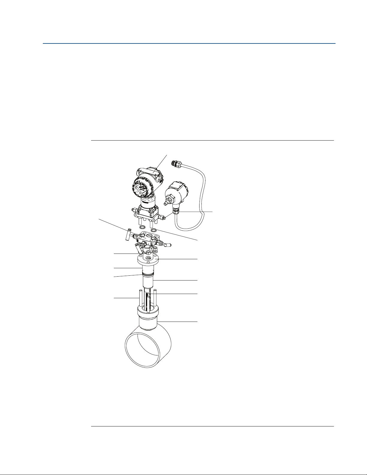
2.6.1 Pak-Lok Annubar sensor type (for 485 Annubar Flowmeters)
Figure 2-14 identifies the components of the Pak-Lok assembly.
Figure 2-14. Components
Transmitter and housing are shown for clarity purposes – only supplied if ordered.
A. Direct mount transmitter connection with valves
B. Nuts
C. Follower
D. Packing rings (3)
E. Studs
F. Transmitter
G. Coplanar flange with drain vents
H. O-rings (2)
I. Compression plate
J. Retaining ring
K. 485 Annubar sensor
L. Pak-Lok body
22
Installation
 Loading...