

Rosemount 2555 Operating Manual
Quick Start Guide
00825-0100-2555, Rev AB
January 2020
Rosemount™ 2555 Solids Level Switches
Capacitance Probe

Quick Start Guide January 2020
Contents
Introduction.................................................................................................................................3
Mechanical installation.................................................................................................................8
Electrical installation.................................................................................................................. 12
Configuration.............................................................................................................................17
Troubleshooting........................................................................................................................ 36
Maintenance.............................................................................................................................. 41
2 Quick Start Guide

January 2020 Quick Start Guide
1 Introduction
The level switch detects the presence and absence of a process media at its
installation point, and reports it as a switched electrical output.
Note
Other language versions of this Quick Start Guide can be found at
Emerson.com/Rosemount.
1.1 Safety messages
NOTICE
Read this manual before working with the product. For personal and system
safety, and for optimum product performance, ensure you thoroughly
understand the contents before installing, using, or maintaining this
product.
For technical assistance, contacts are listed below:
Customer Central
Technical support, quoting, and order-related questions.
• United States - 1-800-999-9307 (7:00 am to 7:00 pm CST)
• Asia Pacific- 65 777 8211
North American Response Center
Equipment service needs.
• 1-800-654-7768 (24 hours a day — includes Canada)
• Outside of these areas, contact your local Emerson representative.
WARNING
Physical access
Unauthorized personnel may potentially cause significant damage to and/or
misconfiguration of end users’ equipment. This could be intentional or
unintentional and needs to be protected against.
Physical security is an important part of any security program and
fundamental to protecting your system. Restrict physical access by
unauthorized personnel to protect end users’ assets. This is true for all
systems used within the facility.
Quick Start Guide 3

Quick Start Guide January 2020
WARNING
Failure to follow safe installation and servicing guidelines could result in
death or serious injury.
• Ensure the level switch is installed by qualified personnel and in
accordance with applicable code of practice.
• Use the level switch only as specified in this manual. Failure to do so may
impair the protection provided by the level switch.
Explosions could result in death or serious injury.
• In explosion-proof/flameproof, non-Incendive/type n, and dust ignition-
proof installations, do not remove the housing cover when power is
applied to the level switch.
• The housing cover must be fully engaged to meet flameproof/explosion-
proof requirements.
Electrical shock could cause death or serious injury.
• Avoid contact with the leads and terminals. High voltage that may be
present on leads can cause electrical shock.
• Ensure the power to the level switch is off, and the lines to any other
external power source are disconnected or not powered while wiring the
level switch.
• Ensure the wiring is suitable for the electrical current and the insulation is
suitable for the voltage, temperature, and environment.
Process leaks could result in death or serious injury.
• Ensure the level switch is handled carefully. If the process seal is
damaged, gas or dust might escape from the silo (or other vessel)
Any substitution of non-recognized parts may jeopardize safety. Repair
(e.g. substitution of components) may also jeopardize safety and is not
allowed under any circumstances.
• Unauthorized changes to the product are strictly prohibited as they may
unintentionally and unpredictably alter performance and jeopardize
safety. Unauthorized changes that interfere with the integrity of the
welds or flanges, such as making additional perforations, compromise
product integrity and safety. Equipment ratings and certifications are no
longer valid on any products that have been damaged or modified
without the prior written permission of Emerson. Any continued use of
product that has been damaged or modified without the written
authorization is at the customer’s sole risk and expense.
4 Quick Start Guide

January 2020 Quick Start Guide
CAUTION
The products described in this document are NOT designed for nuclearqualified applications.
• Using non-nuclear qualified products in applications that require
nuclear-qualified hardware or products may cause inaccurate readings.
• For information on Rosemount nuclear-qualified products, contact your
local Emerson Sales Representative.
Individuals who handle products exposed to a hazardous substance can
avoid injury if they are informed of and understand the hazard.
• If the product being returned was exposed to a hazardous substance as
defined by Occupational Safety and Health Administration (OSHA), a
copy of the required Safety Data Sheet (SDS) for each hazardous
substance identified must be included with the returned level switch.
1.2 Applications
A Rosemount™ 2555 Solids Level Switch is used for monitoring the level of
bulk materials in all types of containers and silos.
Typical applications are:
• Building materials
— Lime, extruded polystyrene foam (XPS), molding sand, etc.
• Food and beverage
— Milk powder, flour, salt, etc.
• Plastics
— Plastic granulates, etc.
• Timber
• Chemicals
The level switch has a threaded, flanged, or Tri Clamp process connection for
mounting it onto a silo (or other vessel). You can mount it on a side wall of
the silo, so that it is level with the filling limit to be monitored. Alternatively,
if it has an extended length, mount it vertically on top of a silo to monitor the
maximum filling limit.
The length of the capacitance probe can be up to 98.4 in. (2.5 m) with a rod
extension tube or up to 787 in. (20 m) with an extension rope.
The use of a sliding sleeve is recommended so that the switching point can
be changed easily during the live operation of the level switch.
Quick Start Guide 5
A
B
C
D
E
F
G
H
I
J
B
K
Quick Start Guide January 2020
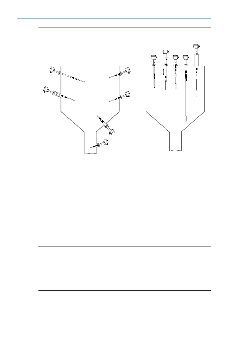
Figure 1-1: Typical Installation Examples
A. Inactive length to reach distance from silo wall
B. Inactive length due to long mounting nozzle
C. Short length (full-silo detection)
D. Short length (on-demand detection)
E. Short length (empty-silo detection)
F. Application in down pipe
G. Inactive length to bring active probe to required level
H. Inactive length and sliding sleeve for adjustable height
I. Rope version (full-silo detection)
J. Rope version (empty-silo detection)
K. Optional sliding sleeve
Active and inactive probe lengths
The active length is always inside the silo and generates an electrical field
between the probe and the silo wall. With active shield technology, the RF
measurements are unaffected by product build-up on the probe. The
inactive length is used to extend the overall probe length.
Note
See the Rosemount 2555 Product Data Sheet for extended length options.
6 Quick Start Guide

January 2020 Quick Start Guide
1.3 Measurement principles
Using the principle of measuring capacitance through RF (Radio Frequency),
the presence or absence of a solids medium is detected by monitoring the
change in capacitance between the probe and the container wall.
When the solids medium in the vessel (silo) falls away from the probe level, it
causes an increase in capacitance that is detected by the electronics and the
output switches to indicate an 'uncovered' state.
When the solids medium in the vessel (silo) rises and covers the rod, it
causes a decrease of capacitance that is detected by the electronics and the
output switches to indicate a 'covered' state.
The electrical output will vary depending on the electronics selected when
the Rosemount 2555 was ordered.
Quick Start Guide 7

Quick Start Guide January 2020
2 Mechanical installation
2.1 Mounting considerations
Before mounting the level switch on a silo (or other vessel), review the safety
and pre-mounting sections.
2.1.1 Safety
General safety
Installation of this equipment shall be carried out by suitably trained
1.
personnel, in accordance with the applicable code of practice.
2. If equipment is likely to come into contact with aggressive
substances, it is the user’s responsibility to take suitable precautions
that prevent it from being adversely affected, thus ensuring the type
of protection is not compromised.
a. Aggressive substances: Acidic liquids or gases that may
attack metals or solvents that may affect polymeric materials.
b. Suitable precautions: Regular checks as part of routine
inspections or establishing from a material's data sheet that it
is resistant to specific chemicals.
3. It is the responsibility of the installer to:
a. Take protective measures, such as fitting an angled shield
(reverse V shape) to the silo or selecting an extension tube
option, when there are high mechanical forces.
b. Ensure that the process connection is tightened by the
correct amount of torque and sealed to prevent process
leaks.
4. Technical data
a. The Rosemount 2555 Product Data Sheet has all the technical
specifications. See Emerson.com/Rosemount for other
language versions.
Hazardous area safety
The Rosemount 2555 Product Certifications document has safety
instructions and control drawings for hazardous area installations. See
Emerson.com/Rosemount for other language versions.
8 Quick Start Guide

A
B
January 2020 Quick Start Guide
2.1.2 Tightening threaded process connections
When tightening the threaded process connection of a Rosemount 2555:
• Use an open-ended wrench on the hexagonal boss of the level switch or
the sliding sleeve.
• Never tighten by using the housing.
• Do not exceed the maximum torque of 80 Nm.
2.1.3 Sliding sleeve
Tighten both M8 screws with a torque of 20 Nm to establish a seal and
maintain the process pressure.
2.1.4 Mechanical load
The load at points A and B (Figure 2-1) must not be exceeded. All ratings are
for 104 °F (40 °C).
Figure 2-1: Maximum Mechanical Loads
Table 2-1: Maximum Mechanical Loads
Rosemount 2555S
Rosemount 2555R
Rosemount 2555M
Rosemount 2555P
Rosemount 2555E
Rosemount 2555V
Rod version:
Rope version:
Rod version:
Rope version:
Rod version:
Rope version:
A: 125 Nm
4 kN tensile load
A: 525 Nm
40 kN tensile load
A: 525 Nm
10 kN tensile load
B: 20 Nm
B: 90 Nm
B: 20 Nm
2.1.5 Orientation of cable glands
When the level switch is mounted horizontally, ensure the cable glands are
pointed downwards to avoid water getting inside the housing. Unused
conduit entries must be completely sealed with a suitably rated stopping
(blanking) plug.
Quick Start Guide 9
> 2 (50)
> 3.9
(100)
> 3.9
(100)
> 7.9
(200)
Quick Start Guide January 2020
2.1.6 Future maintenance
It is advisable to grease the screws of the housing cover (lid) when a
corrosive atmosphere is present. This will help prevent difficulties when the
cover needs to be removed during future maintenance tasks.
2.1.7 Hygienic applications
The food-grade materials are suitable for use under normal and predictable
hygienic applications (according to directive 1935/2004 Art.3). There are
currently no hygienic certifications for the Rosemount 2555.
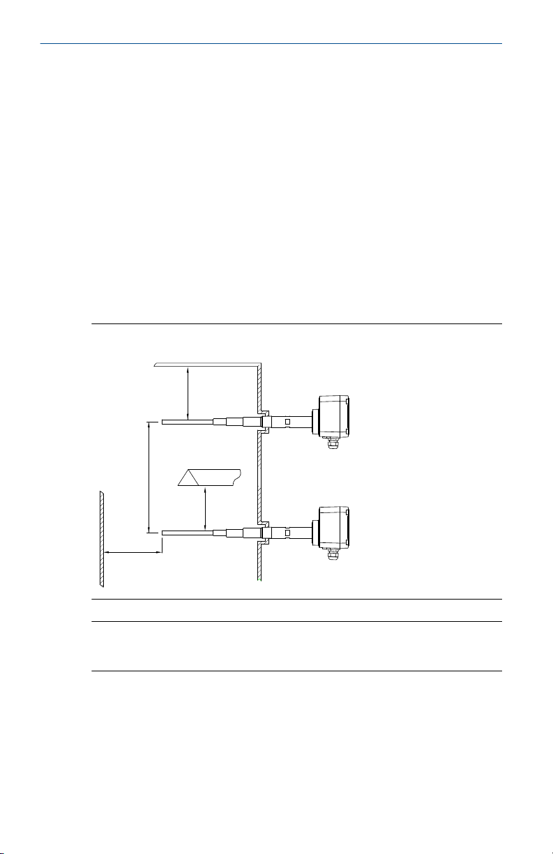
2.1.8 Minimum distances
Figure 2-2 shows the minimum distances required between installed level
switches, the walls of a silo, and a protective shield. The installation of a
protective angled shield above the level switch is recommended depending
on the type of bulk solids.
Figure 2-2: Minimum Distances
Note
Avoid installing the level switch directly under the flow of solids material
(filling point).
2.1.9 Grounding (earthing)
10 Quick Start Guide
The external ground screw must be connected to a grounding point at the
installation site. An internal ground screw is already connected internally and
requires no further action.
> 1.8
(50)
A
> 1.8
(50)
A
> 1.8
(50)
A
> 1.8
(50)
A
OK
OK OK
OK
E
F
G
C
D
B
January 2020 Quick Start Guide
See Wiring the level switch for further information about grounding
(earthing) the level switch.
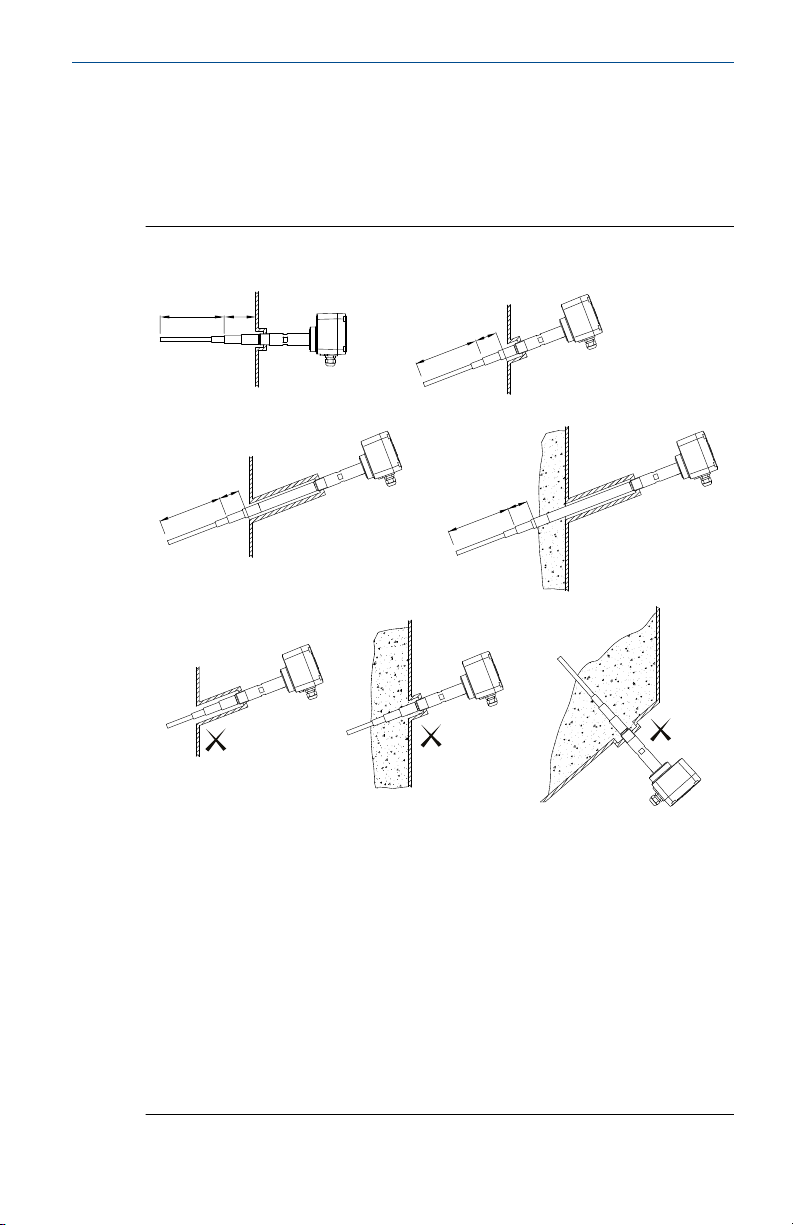
2.2 Mounting the level switch
Figure 2-3 shows how the level switch should be mounted.
Figure 2-3: Correct and Incorrect Mounting
A. Active probe
B. Mounting the level switch at an angle helps solids material to fall away
and prevent build-up
C. Correct installation: The inactive length is correctly used with a long
socket
D. Correct installation: The inactive length is correctly used even though
there is a build-up of solids material
E. Incorrect installation: The active probe is inside the socket
F. Incorrect installation: The active probe is covered by a build-up of
material and is not detecting the true level
G. Incorrect installation: The active probe is located where solids material
would remain, even in an empty silo
Quick Start Guide 11

Quick Start Guide January 2020
3 Electrical installation
3.1 Wiring considerations
Note
See the Rosemount 2555 Product Data Sheet for the full electrical
specifications.
3.1.1 Handling
In cases of improper handling or handling malpractice, the electrical safety
of the device cannot be guaranteed.
3.1.2 Protective earthing
Before any electrical installation, the device must be connected to the
protective earthing terminal inside the housing.
3.1.3 Installation regulations
Local regulations or VDE 0100 (Regulations of German Electrotechnical
Engineers) must be observed.
When using 24 V supply voltage, an approved power supply with reinforced
insulation to mains is required.
3.1.4 Fuse
Use a fuse as stated in the connection diagrams.
For details, see Wiring the level switch.
3.1.5 Residual Current Circuit Breaker (RCCB) protection
In case of a defect, the distribution voltage must automatically be cut-off by
an RCCB protection switch to protect against indirect contact with
dangerous voltages.
3.1.6 Power supply
Power supply switch
A voltage disconnection switch must be provided near the device.
Supply voltage
Compare the supply voltage applied with the specifications given on the
electronic module and nameplate before switching on the device.
12 Quick Start Guide

January 2020 Quick Start Guide
3.1.7 Wiring
Field wiring cables
The diameter has to match the clamping range of the used cable gland.
The cross-section has to match the clamping range of the connection
terminals and the maximum current must be considered.
All field wiring must have insulation suitable for at least 250 Vac.
The temperature rating must be at least 194 °F (90 °C).
Use a shielded cable when there are electrical interferences present that are
higher than stated in the EMC standards. Otherwise, an unshielded
instrumentation cable can be used.
Wiring diagram
The electrical connections are made in accordance with the wiring diagram.
Guiding the cables in the terminal box
The field wiring cables must be cut to a length to be able to properly fit them
into the terminal box.
3.1.8 Cable glands
The screwed cable gland and stopping plug must have the following
specifications:
• Ingress protection IP67
• Temperature range from -40 °C to +80 °C
• Hazardous area certification (depending on where the unit is installed)
• Pull relief
Ensure the screwed cable gland safely seals the cable and is tight enough to
prevent water ingress. Unused conduit or cable entries must be sealed with a
stopping (blanking) plug.
A strain relief must be provided for the field wiring cables when the device is
installed with the factory-provided cable glands.
Cable glands and conduit system for ATEX or IECEx
The installation must comply with the regulations of the country where the
level switch is installed.
Unused entries have to be closed with suitably rated stopping (blanking)
plugs.
Where available, the factory-provided parts must be used.
Quick Start Guide 13

Quick Start Guide January 2020
The diameter of the field wiring cable must match the clamping range of the
cable clamp.
If factory-provided parts are not used, the following must be ensured:
• The parts must have an approval adequate to the approval of the level
sensor (certificate and type of protection).
• The approved temperature range must be between the minimum
ambient temperature of the level sensor and the maximum ambient
temperature of the level sensor increased by 10 K.
• The parts must be mounted according to the instructions of the
manufacturer.
3.1.9 Conduit system
When a threaded conduit system is used instead of a cable gland, the
regulations of the country must be observed. The conduit must have a ½-in.
NPT tapered thread to match a NPT threaded conduit entry of the level
switch and comply with ANSI B 1.20.1. Unused conduit entries must be
closed tightly with a metal stopping (blanking) plug.
Conduit system for FM
The regulations of the country must be observed. The flameproof seals and
stopping (blanking) plugs must have an adequate type approval and a
temperature range of at least -40 to 176 °F (–40 to +80 °C). In addition, they
must be suitable for the conditions and correctly installed. Where available,
the original provided parts of the manufacturer must be used.
3.1.10 Connection terminals
When preparing cable wires for connection to terminals, the wire insulation
must be stripped to show no more than 0.31 in. (8 mm) of the copper
strands. Always check that the power supply is disconnected or switched-off
to avoid coming into contact with dangerous live parts.
3.1.11 Relay and transistor protection
Provide protection for relay contacts and output transistors to protect the
device against inductive load surges.
3.1.12 Static charging
The Rosemount 2555 must be grounded to avoid a static electrical build-up.
This is particularly important for applications with pneumatic conveying and
non-metallic containers.
14 Quick Start Guide
 Loading...