


Quick Start Guide
00825-0100-4160, Rev CB
Rosemount™ 2160 Wireless Level
Detector
Vibrating Fork
September 2020

Quick Start Guide September 2020
Contents
About this guide...........................................................................................................................3
Installation................................................................................................................................... 6
Configuration.............................................................................................................................14
Product certifications................................................................................................................. 22
2 Rosemount 2160 Wireless Level Detector

September 2020 Quick Start Guide
1 About this guide
This Quick Start Guide provides basic guidelines for the Rosemount 2160.
Refer to the Rosemount 2160 Reference Manual for more instructions. The
manual and this guide are also available electronically at Emerson.com/
Rosemount.
NOTICE
Power module considerations.
• Each Power Module contains two "C" size primary lithium/thionyl chloride
batteries. Each battery contains approximately 2.5 grams of lithium, for
a total of 5 grams in each pack. Under normal conditions, the battery
materials are self-contained and are not reactive as long as the batteries
and the pack integrity are maintained. Care should be taken to prevent
thermal, electrical or mechanical damage. Contacts should be protected
to prevent premature discharge.
• Battery hazards remain when cells are discharged.
• Use caution when handling the power module. The Power Module may
be damaged if dropped from heights in excess of 20 ft. (6 m).
• Power modules should be stored in a clean and dry area. For maximum
battery life, storage temperature should not exceed 86 °F (30 °C).
• The power module may be replaced in a hazardous area. The power
module has surface resistivity greater than one gigaohm and must be
properly installed in the wireless device enclosure. Care must be taken
during transportation to and from the point of installation to prevent
electrostatic charge build-up.
Shipping considerations for wireless products.
• The unit was shipped to you without the power module installed.
Remove the power module prior to shipping.
• Each power module contains two “C” size primary lithium batteries.
Primary lithium batteries are regulated in transportation by the U. S.
Department of Transportation, and are also covered by IATA
(International Air Transport Association), ICAO (International Civil
Aviation Organization), and ARD (European Ground Transportation of
Dangerous Goods). It is the responsibility of the shipper to ensure
compliance with these or any other local requirements. Consult current
regulations and requirements before shipping.
Quick Start Guide 3

Quick Start Guide September 2020
WARNING
Failure to follow safe installation and servicing guidelines could result in
death or serious injury.
• Ensure the level detector is installed by qualified personnel and in
accordance with applicable code of practice.
• Use the level detector only as specified in this manual. Failure to do so
may impair the protection provided by the level detector.
• The weight of a level detector with a heavy flange and extended fork
length may exceed 37 lb. (18 kg). A risk assessment is required before
carrying, lifting, and installing the level detector.
Explosions could result in death or serious injury.
• Verify that the operating atmosphere of the level detector is consistent
with the appropriate hazardous locations certifications.
• Before connecting a handheld communicator in an explosive
atmosphere, ensure that the instruments in the loop are installed in
accordance with intrinsically safe or non-incendive field wiring practices.
• In explosion-proof/flameproof and non-incendive/type n installations, do
not remove the housing covers when power is applied to the level
detector.
• Both housing covers must be fully engaged to meet flameproof/
explosion-proof requirements.
WARNING
Process leaks could result in death or serious injury.
• Ensure the level detector is handled carefully. If the process seal is
damaged, gas might escape from the vessel (tank) or pipe.
4 Rosemount 2160 Wireless Level Detector

September 2020 Quick Start Guide
WARNING
Physical access
Unauthorized personnel may potentially cause significant damage to and/or
misconfiguration of end users’ equipment. This could be intentional or
unintentional and needs to be protected against.
Physical security is an important part of any security program and
fundamental to protecting your system. Restrict physical access by
unauthorized personnel to protect end users’ assets. This is true for all
systems used within the facility.
CAUTION
Hot surfaces
The flange and process seal may be hot at high process
temperatures.
Allow to cool before servicing.
Quick Start Guide 5

OK
OK
A
B
A
B
OK
OK
OK
C
A
B
Quick Start Guide September 2020
2 Installation
2.1 Fork alignment in a pipe installation
Figure 2-1: Correct Fork Alignment for Pipe Installation
A. Tri Clamp process connections have a circular notch
B. Threaded process connections have a groove
2.2 Fork alignment in a vessel (tank) installation
Figure 2-2: Correct Fork Alignment for Vessel (Tank) Installation
6 Rosemount 2160 Wireless Level Detector
A. Tri Clamp process connections have a circular notch
B. Threaded process connections have a groove
Flanged process connections have a circular notch
C.

A
B
A
B
September 2020 Quick Start Guide
2.3 Mounting the threaded version
2.3.1 Seal and protect the threads
• Use anti-seize paste or PTFE tape according to site procedures.
A gasket may be used as a sealant for BSPP (G) threaded connections.
2.3.2 Threaded vessel (tank) or pipework connection
• Vertical installation.
• Horizontal installation.
A. Tighten using the hexagon nut only
B. Gasket for BSPP (G) threaded connection
Quick Start Guide 7

A
A
Quick Start Guide September 2020
2.3.3 Threaded flange connection
Procedure
1. Place the customer-supplied flange and gasket on the vessel (tank)
nozzle.
A. Gasket (customer supplied)
2.
Tighten the bolts and nuts with sufficient torque for the flange and
gasket.
3. Screw the level detector into the flange thread.
A. Tighten using the hexagon nut only
B. Gasket for BSPP (G) threaded connection
8 Rosemount 2160 Wireless Level Detector

A
September 2020 Quick Start Guide
2.4 Mounting the flanged version
Procedure
1. Lower the level detector into the nozzle.
A. Gasket (customer supplied)
2. Tighten the bolts and nuts with sufficient torque for the flange and
gasket.
Quick Start Guide 9

A
Quick Start Guide September 2020
2.5 Mounting the Tri Clamp version
Procedure
1. Lower the level detector into the flange face.
A. Seal (supplied with Tri Clamp)
2. Fit the Tri Clamp.
10 Rosemount 2160 Wireless Level Detector

A
B
September 2020 Quick Start Guide
2.6 Wireless battery installation
To install the battery that supplies all power to the Rosemount 2160:
Procedure
Remove the housing cover on the battery compartment side.
1.
2.
Connect the battery.
3. Replace the battery cover and tighten to safety specification (metalto-metal).
Figure 2-3: Wireless Battery Installation
A. Battery cover
Battery
B.
Quick Start Guide 11

Quick Start Guide September 2020
2.7 Position the antenna
The antenna should be positioned vertically, either straight up or straight
down, and it should be approximately 3 ft. (1 m) from any large structure,
building, or conductive surface to allow for clear communication to other
devices.
Figure 2-4: Antenna Positioned Vertically
2.8 Adjust LCD meter orientation (optional)
If a device display is ordered, it will be shipped attached to the level detector.
The display is ordered in the level detector model number, option code M5.
2.8.1 Rotate the device display
The device display can be rotated in 90-degree increments.
Procedure
1.
Squeeze the two black tabs on opposite sides of the display.
2. Gently pull out the display.
3. Rotate the display to the desired orientation, and snap the display
into place.
Note
If the device display four-pin connector is inadvertently removed
from the interface board, carefully re-insert the connector before
snapping the device display back into place.
12 Rosemount 2160 Wireless Level Detector

A
H
3
/32 in.
Torque 30 in-lb (3 Nm)
September 2020 Quick Start Guide
2.9 Adjust housing orientation (optional)
To improve field access to wiring or to better view the optional LCD display:
Procedure
Loosen the set screw until the level detector housing can rotate
1.
smoothly.
Do not unscrew all the way. Rotating the housing, without this screw
in place, can damage the internal wiring.
2.
First, rotate the housing clockwise to the desired location.
If the desired location cannot be achieved due to thread limit, rotate
the housing counterclockwise.
3. Re-tighten the set screw.
Figure 2-5: Housing Rotation
A. Do not attempt to rotate the housing beyond the thread limit
Quick Start Guide 13

Quick Start Guide September 2020
3 Configuration
3.1 Configuration procedure
Follow these steps for proper configuration:
Procedure
Get started with your preferred configuration tool.
1.
a)
AMS Wireless Configurator (see AMS Wireless Configurator)
b) Handheld communicator
2. Join device to wireless network.
a) Insert the power module (see Wireless battery installation).
b) Connect to device (see Connect to device).
c) Configure update rate (see Configure update rate).
d) Obtain network ID and join key.
e) Enter network ID and join key.
f) Verify device joins Network.
3. Configure device.
a) Connect to device (see Connect to device).
b) Configure using basic setup.
c) Consider optional guided setups.
4. Verify the fork status (dry or wet) is as expected.
3.2 Get started with your preferred configuration tool
3.2.1 AMS Wireless Configurator
The AMS Wireless Configurator is the recommended software tool for
wireless network devices, and is supplied with the Emerson Wireless
Gateway. Refer to the AMS Wireless Configurator Manual Supplement for
further information.
Configuration can be done by connecting to the wireless network devices
either point-to-point using a HART modem or wirelessly through the
Gateway (see Figure 3-1). Initial configuration to join a device to the wireless
network must be done point-to-point.
14 Rosemount 2160 Wireless Level Detector

September 2020 Quick Start Guide
Get the latest Device Descriptor (DD)
The Device Descriptor (DD) is a support file containing the information
required by host systems and handheld communicators to utilize the
capabilities and functions of a field instrument.
Prerequisites
The Rosemount 2160 DD is typically installed together with AMS Wireless
Configurator. To download the latest HART® DD, visit the Emerson Device
Install Kit site at: Emerson.com/DeviceInstallKits
Procedure
After downloading, add the DD to AMS Wireless Configurator.
Close AMS Wireless Configurator.
a)
b) Go to Start → Programs → AMS Device Manager and select Add
Device Type.
c) Browse to the downloaded DD files and select OK.
Need help?
In the Add Device Type application, select the Help button for more
information on how to complete this operation.
Configure the HART® modem interface
Before connecting to the device using a HART modem, the HART modem
interface must be configured in AMS Wireless Configurator.
Procedure
1.
Close AMS Wireless Configurator.
Go to Start → Programs → AMS Device Manager and select
2.
Network Configuration.
3. Select Add.
4. In the drop down list, select HART modem and then select Install.
5. Follow the on-screen instructions.
Need help?
In the Network Configuration application, select the Help button for more
information on how to complete this operation.
Quick Start Guide 15

Quick Start Guide September 2020
Configure the wireless network interface
Before connecting to the device wirelessly using a Wireless Gateway, the
wireless network must be configured in AMS Wireless Configurator.
Procedure
1.
Close AMS Wireless Configurator.
2. Go to Start → Programs → AMS Device Manager and select
Network Configuration.
3. Select Add.
4. In the drop-down list select Wireless Network and then select
Install.
5. Follow the on-screen instructions.
Need help?
In the Network Configuration application, select the Help button for more
information on how to complete this operation.
3.2.2 Handheld communicator
Configuration can be done by connecting to the wireless network devices
directly to the communication terminals of the level detector (see Figure
3-1).
Get the latest Device Descriptor (DD)
If the DD is not installed on a handheld communicator supplied by Emerson,
see the appropriate User’s Manual available at Emerson.com/
FieldCommunicator for instructions on how to update to the latest DD.
3.3 Join device to wireless network
3.3.1 Power up the wireless device
Prerequisites
Make sure that the Wireless Gateway is installed and functioning properly
before any wireless field devices are powered.
Wireless devices should be powered up in order of proximity from the
Gateway, beginning with the closest. This will result in a simpler and faster
network installation.
Procedure
1.
Install the power module.
Wireless battery installation for the procedure.
See
2. Enable Active Advertising on the Gateway to ensure that new
devices join the network faster.
16 Rosemount 2160 Wireless Level Detector

$
&
%
1 2 3
4 5 6
7 809
September 2020 Quick Start Guide
See the Emerson Wireless Gateway Reference Manual for more
information.
3.3.2 Connect to device
Procedure
1. Connect a handheld communicator or a HART® modem to the
communication terminals as shown in Figure 3-1.
2. Do one of the following:
• AMS Wireless Configurator:
a. Start AMS Wireless Configurator.
b. Select View → Device Connection View.
c. Double click the device under the HART modem.
• Handheld communicator:
— Turn on the handheld communicator and connect to the
device.
Figure 3-1: Connect to Device
A. Communication terminals
B. Handheld communicator
HART modem
C.
Quick Start Guide 17

Quick Start Guide September 2020
3.3.3 Configure update rate
The Update Rate is the frequency at which a new measurement is
transmitted over the wireless network. The default update rate is 1 minute.
This may be changed at commissioning, or at any time using AMS Wireless
Configurator or a handheld communicator. The update rate is user
selectable from 4 seconds to 60 minutes.
Procedure
1.
2. Select Configure Update Rate, and follow the instructions.
Configure → Guided Setup → Wireless Setup.
Select
Note
If the time between each update is too long, the high/low alerts may
be triggered too late.
3.3.4 Obtain the Network ID and join key
In order to communicate with the Wireless Gateway, and ultimately the host
system, the level detector must be configured to communicate on the
wireless network. This step is the wireless equivalent of connecting wires
from a level detector to the host system.
Procedure
• From the Wireless Gateway's integrated web interface, select Setup →
Network → Settings.
3.3.5 Enter network ID and join key
The level detector must be configured with the same Network ID and Join
Key as the Wireless Gateway in order to join the network. Use AMS Wireless
Configurator or a handheld communicator to enter the Network ID and Join
Key.
Procedure
1.
Select
Configure → Guided Setup → Wireless Setup.
2. Select Join Device to Network, and follow the instructions.
Postrequisites
If the level detector is not to be commissioned yet, remove the power
module and fasten the housing cover. This is to conserve power module life
and to ensure safe transportation of the level detector. The power module
should be inserted only when the device is ready to be commissioned.
18 Rosemount 2160 Wireless Level Detector
September 2020 Quick Start Guide
3.3.6 Verify the wireless network has been joined
The wireless network connection can be verified in four ways, further
described in this section:
• At the optional display
• Using AMS Wireless Configurator
• In the Wireless Gateway's integrated web interface
• Using a handheld communicator
If the level detector was correctly configured with the Network ID and Join
Key, and sufficient time has passed, the level detector should be connected
to the wireless network. It usually takes a few minutes to join the wireless
network. If the wireless network has not been joined, see the
troubleshooting section in the Rosemount 2160 Reference Manual.
Verify by using the optional display
Procedure
1.
Unscrew the display cover.
Press the DIAG button.
2.
The display will show: Tag, Device Serial Number, Network ID,
Network Connection Status, and Supply Voltage screens. .
When the network diagnostic status is displayed as “NETWK OK”, the
wireless network has been joined successfully.
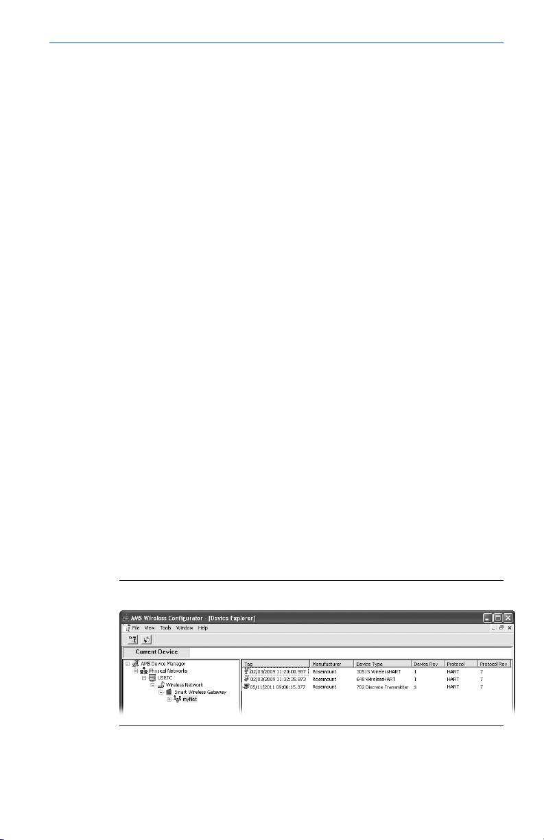
Verify with AMS Wireless Configurator
Procedure
• Start the AMS Wireless Configurator.
When the device has joined the network, it appears in the AMS Wireless
Configurator window (see Figure 3-2).
Figure 3-2: AMS Wireless Configurator Screen
Quick Start Guide 19

Quick Start Guide September 2020
Verify by Gateway
Procedure
1.
To use the Wireless Gateway's integrated web interface, navigate to
the Explorer → Status page.
This page shows the current devices joined to the wireless network
and communicating properly.
2. Locate the level detector in the HART Tag column and verify all status
indicators are good (green).
It may take several minutes for the level detector to join the wireless
network and be seen on the Gateway's integrated web interface.
Verify by using a handheld communicator
Prerequisites
Do not remove the power module. Removing the power module may cause
the device to drop off the network.
Note
In order to communicate with a handheld communicator, the device must
be powered by the power module.
Procedure
1. Connect the handheld communicator (see
2. Select Service Tools → Communications.
3. Select Join Status.
Figure 3-1).
3.4 Configure device using Guided Setup
The options available in the Guided Setup wizard include all items required
for basic operation. All basic configuration parameters are described in
Configuration Parameters.
3.4.1 Start Guided Basic Setup using AMS Wireless Configurator
The options available in the Basic Setup wizard include all items required for
basic operation.
Procedure
1.
Start AMS Wireless Configurator.
Select View → Device Connection View.
2.
3. Double-click the device icon.
4. Select Configure → Guided Setup.
5. Select Basic Setup and follow the on-screen instructions.
20 Rosemount 2160 Wireless Level Detector

September 2020 Quick Start Guide
3.4.2 Start Guided Basic Setup using a handheld communicator
The options available in the Basic Setup wizard include all items required for
basic operation.
Procedure
1.
Turn on the handheld communicator and connect to the level
detector.
Select Configure → Guided Setup.
2.
3. Select Basic Setup and follow the on-screen instructions.
3.4.3 Optional guided setups
Consider optional guided setups such as Configure Device Display and
Configure Alerts.
Procedure
1.
Select
Configure → Guided Setup.
2. Select the desired wizard, and follow the instructions.
Additional configuration parameters are available in the Manual
Setup menu.
Quick Start Guide 21

Quick Start Guide September 2020
4 Product certifications
4.1 European Union directive information
The most recent revision of the EU Declaration of Conformity can be found
at Emerson.com/Rosemount.
4.2 Telecommunication compliance
All wireless devices require certification to ensure that they adhere to
regulations regarding the use of the RF spectrum. Nearly every country
requires this type of product certification. Emerson is working with
governmental agencies around the world to supply fully compliant products
and remove the risk of violating country directives or laws governing
wireless device usage.
4.3 FCC and IC
This device complies with Part 15 of the FCC Rules. Operation is subject to
the following conditions: This device may not cause harmful interference
and this device must accept any interference, including any interference that
may cause undesired operation of the device. This device must be installed
to ensure a minimum antenna separation distance of 8 in. (20 cm) from all
persons.
4.4 Overfill approval
Certificate
TÜV-tested and approved for overfill protection according to the German
DIBt/WHG regulations. Certified under safety devices for tanks and piping
related to water pollution control.
Z-65.11-518
4.5 NAMUR approval
The NAMUR NE95 type test report is available upon request. Complies with
NAMUR NE21.
22 Rosemount 2160 Wireless Level Detector

September 2020 Quick Start Guide
4.6 U.S.A.
4.6.1 Intrinsic Safety (IS), Non-Incendive (NI), Dust Ignition-proof (DIP)
I5
Summary of product certification
Protections
Project ID
Markings
Enclosure
Special Conditions for Safe Use
1. Use with Rosemount SmartPower® option P/N 753-9220-0001 only.
2. Warning – Potential Electrostatic Charging Hazard – The enclosure is
partially constructed from plastic. To prevent the risk of electrostatic
sparking, use only a damp cloth to clean the plastic surfaces.
Intrinsic Safety (IS)
Non-Incendive (NI)
Dust Ignition-proof (DIP)
3036541
IS Class I/II/III, Division 1, Groups A, B, C, D, E, F, and G
IS Class I, Zone 0, AEx ia IIC
NI Class I, Division 2, Groups A, B, C, and D
DIP Class II/III, Division 1, Groups E, F, and G
T4 (Ta = -58 °F to +158 °F / -50 °C to +70 °C)
Type 4X / IP66
4.7 Canada
4.7.1 Canada Intrinsic Safety (IS)
I6
Summary of product certification
Protections
Project ID
Markings
Control
drawing
Enclosure
Special Condition for Safe Use
Use with Rosemount SmartPower® option P/N 753-9220-0001 only.
Quick Start Guide 23
Intrinsic Safety (IS)
1786345
Class I, Division 1, Groups A, B, C, and D, T3C
Intrinsically Safe when installed in accordance with Rosemount
drawing 71097/1271
Type 4X / IP66
Single process seal

Quick Start Guide September 2020
4.7.2 Canadian Registration Number
CRN
0F04227.2C
The requirements of CRN are met when a Rosemount 2160 CSA-approved
vibrating fork level detector model is configured with 316/316L stainless
steel (1.4401/1.4404) process-wetted parts and either NPT threaded or 2-in.
to 8-in. ASME B16.5 flanged process connections.
4.8 Europe
4.8.1 ATEX Intrinsic Safety (IS)
I1
Summary of product certification
Protection
Certificate
Markings
Safety
instructions
Special Conditions For Safe Use (X)
1. Use with Rosemount SmartPower options P/N 753-9220-0001 only.
Intrinsic Safety (IS) for gas atmospheres
Baseefa 09ATEX0253X
II 1 G
Ex ia IIC T5...T2 Ga
IP66
See Instructions for hazardous area installations (I1 and I7)
2. The surface resistivity of the antenna is greater than 1 GΩ. To avoid
electrostatic charge build-up, it must not be rubbed or cleaned with
solvents or a dry cloth.
3. The Rosemount 2160 enclosure is made of aluminum alloy and given
a protective epoxy coating; however, care should be taken to protect
it from impact or abrasion if located in a Zone 0.
24 Rosemount 2160 Wireless Level Detector

September 2020 Quick Start Guide
4.9 International
4.9.1 IECEx Intrinsic Safety (IS)
I7
Summary of product certification
Protection
Certificate
Markings
Safety
instructions
Special Conditions for Safe Use
1. For use with Rosemount SmartPower options P/N 753-9220-0001
only.
2. The surface resistivity of the polymeric antenna is greater than 1GΩ.
To avoid electrostatic charge build-up, it shall not be rubbed or
cleaned with solvents or a dry cloth.
3. Warning – potential electrostatic charging hazard – The enclosure is
partially constructed from plastic. To prevent the risk of electrostatic
sparking, use only a damp cloth to clean the plastic surfaces.
Intrinsic Safety (IS) for gas atmospheres
IECEx BAS 09.0123X
Ex ia IIC T5-T2
IP66
See Instructions for hazardous area installations (I1 and I7)
4.10 Korea
4.10.1 KTL Intrinsic Safety (IS)
IP
Summary of product certification
Protection
Certificates
Markings
4.10.2 Korean Testing Laboratory (KTL), KCC mark for ordinary locations use
GP
Certificate
Quick Start Guide 25
Intrinsic Safety (IS)
13-KB4BO-0213X
Ex ia IIC T5...T2
Ta (see table in the certificate)
KCC-REM-ERN-RMDSWIT2160XXX

Quick Start Guide September 2020
4.11 China
4.11.1 NEPSI Intrinsic Safety (IS)
I3
Summary of product certification
Protection
Certificate
Standards
Markings
Safety
instructions
Special Conditions for Safe Use
1. The 701PBKKF SmartPower Black Power Module (p/n
00753-9220-0001) provided by the manufacturer should be used.
2. The surface resistivity of the polymeric antenna is greater than 1 GΩ.
To avoid electrostatic charge build-up, it shall not be rubbed or
cleaned with solvents or a dry cloth.
Intrinsic Safety (IS)
GYJ20.1149X (CCC 认证)
GB 3836.1-2010
GB 3836.4-2010
GB 3836.20-2010
Ex ia IIC T5-T2 Ga
See the certificate.
3. The Rosemount 2160 enclosure is made of aluminum alloy and given
a protective epoxy coating. However, care should be taken to protect
it from impact or abrasion if located in Zone 0.
4.12 Technical Regulations Customs Union (EAC)
4.12.1 Technical Regulation Customs Union (EAC) Intrinsic Safety (IS)
IM
Summary of product certification
Protection
Certificate
Markings
Special Conditions For Safe Use (X)
See certificate for special conditions
26 Rosemount 2160 Wireless Level Detector
Intrinsic Safety (IS)
RU C-GB.AB72.B.00916
0Ex ia IIC T5...T2 Ga X
Ta (see table in the certificate)

September 2020 Quick Start Guide
4.13 Instructions for hazardous area installations (I1 and I7)
Model numbers covered:
2160X**S***********I1******
2160X**E***********I1******
2160X**S***********I7******
2160X**E***********I7******
(“*” indicates options in construction, function, and materials).
The Rosemount 2160 may be used in a hazardous area with
1.
flammable gases and vapors with apparatus groups IIC, IIB and IIA,
and temperature classes T1 to T5. The temperature class of the
installation will be determined from the highest process or ambient
temperature. The temperature class of the installation will be
determined from the highest process or ambient temperature.
2.
It is a special condition of the certification that the temperature of
the electronics housing is in the range of –50 to 70 °C. The
Rosemount 2160 must not be used outside this range. Limit the
external ambient temperature if the process temperature is high.
3. Suitably trained personnel shall carry out installation in accordance
with the applicable code of practice.
4. The user should not repair this equipment.
5. If equipment is likely to come into contact with aggressive
substances, it is the user’s responsibility to take suitable precautions
that prevent it from being adversely affected, thus ensuring the type
of protection is not compromised.
Aggressive substances: Acidic liquids or gases that may attack
metals or solvents that may affect polymeric materials.
Suitable precautions: Regular checks as part of routine inspections
or establishing from a material's data sheet that it is resistant to
specific chemicals.
6. Special conditions of use
a. The user is to ensure the ambient air temperature (Ta) and
the process temperature (Tp) are within the range detailed
above for the T class of the specific flammable gases or vapors
present.
b. The surface resistivity of the antenna is greater than 1
gigaohm. To avoid electrostatic charge build-up, it must not
be rubbed or cleaned with solvents or a dry cloth.
Quick Start Guide 27

Quick Start Guide September 2020
c. The Rosemount 2160 enclosure is made of aluminum alloy
and given a protective epoxy coating; however, care should
be taken to protect it from impact or abrasion if located in an
area where Equipment Protection Level Ga is required (Zone 0
locations).
7.
Technical data
ATEX coding: II 1 G, Ex ia IIC T5...T2 Ga
a.
b. IECEx coding: Ex ia IIC T5-T2
c. Temperature:
2160X**S***********I1******,
2160X**S***********I7******:
Temperature
classes
T5,T4,T3,T2,T1 104 °F (40 °C) 176 °F (80 °C)
T4,T3,T2,T1 158 °F (70 °C) 212 °F (100 °C)
T4,T3,T2,T1 140 °F (60 °C) 239 °F (115 °C)
T3,T2,T1 122 °F (50 °C) 302 °F (150 °C)
Maximum ambient
air temperature
(Ta)
Maximum process
temperature (Tp)
Minimum ambient air temperature (Ta) = –40 °F (–40 °C)
Minimum process temperature (Tp) = –40 °F (–40 °C)
2160X**E***********I1******,
2160X**E***********I7******:
Temperature
classes
T5,T4,T3,T2,T1 104 °F (40 °C) 176 °F (80 °C)
T4,T3,T2,T1 158 °F (70 °C) 239 °F (115 °C)
T3,T2,T1 149 °F (65 °C) 365 °F (185 °C)
T2,T1 140 °F (60 °C) 500 °F (260 °C)
Maximum ambient
air temperature
(Ta)
Maximum process
temperature (Tp)
Minimum ambient air temperature (Ta) = –58 °F (–50 °C)
Minimum process temperature (Tp) = –94 °F (–70 °C)
d.
Materials: Refer to the Rosemount 2160
Product Data Sheet.
e. Year of manufacture: Printed on the product label.
28 Rosemount 2160 Wireless Level Detector

EU Declar
ation of Conformity
No: RMD 1076 Rev. I
n
e 3 fo 1 egaP
W
e,
Rosemount Tank Radar AB
Layoutvägen 1
S-435 33 MÖLNLYCKE
Sweden
declare under our sole responsibility that the product,
Rosemount™ 2160 Series
WirelessHART™ Vibrating Fork Liquid Level Switch
manufactured by,
Rosemount Tank Radar AB
Layoutvägen 1
S-435 33 MÖLNLYCKE
Sweden
to which this declaration relates, is in conformity with the provisions of the European Union
Directives, including the latest amendments, as shown in the attached schedule.
Assumption of conformity is based on the application of the harmonized standards and, when
applicable or required, a European Union notified body certification, as shown in the attached
schedule.
(signature)
Manager Product Approvals
(function)
Dajana Prastalo
(name)
28-Aug-20;
(date of issue)
September 2020 Quick Start Guide
4.14 EU Declaration of Conformity
Figure 4-1: EU Declaration of Conformity (Page 1)
Quick Start Guide 29

EU Declara
tion of Conformity
No: RMD 1076 Rev. I
n
e 3 fo 2 egaP
EMC Directive (2014/30/EU)
All Models
Harmonized Standards: EN 61326-1:2013
RED Directive (2014/53/EU)
All Models
Harmonized Standards: EN 300 328: V2.1.1
Other Standards Used: EN 301 489-1: V2.2.0
EN 301 489-17: V3.2.0
EN 61010-1:2010
ATEX Directive (2014/34/EU)
Rosemount 2160X**************I1WA3WK1*
Baseefa 09ATEX0253X – Intrinsically safe
Equipment Group II, Category 1 G (Ex ia IIC T5…T2 Ga)
Harmonized Standards: EN 60079-0:2018
EN 60079-11:2012
(Minor variations in design to suit the application and/or mountin g requirements are identified by alpha/numeric
characters where
indicated * above)
Quick Start Guide September 2020
Figure 4-2: EU Declaration of Conformity (Page 2)
30 Rosemount 2160 Wireless Level Detector

EU Declara
tion of Conformity
No: RMD 1076 Rev. I
n
e 3 fo 3 egaP
ATEX Notified Body
SGS Fimko Oy [Notified Body Number: 0598]
Särkiniementie 3
P.O. Box 30
FI-00211, Helsinki
Finland
ATEX Notified body for Quality Assurance
DNV Nemko Presafe AS [Notified Body Number: 2460]
Veritasveien 1
1322 HØVIK
Norway
September 2020 Quick Start Guide
Figure 4-3: EU Declaration of Conformity (Page 3)
Quick Start Guide 31

含含有有
China RoHS
管管控控物物质质超超过过最最大大浓浓度度限限值值的的部部件件型型号号列列表表
Rosemount 2160
List of Rosemount 2160 Parts with China RoHS Concent ration above MCVs
部部件件 名名称称
Part Name
有有害害 物物质质 / Hazardous Substances
铅铅
Lead
(Pb)
汞汞
Mercury
(Hg)
镉镉
Cadmium
(Cd)
六六价价 铬铬
Hexavalent
Chromium
(Cr +6)
多多溴溴 联联苯苯
Polybrominated
biphenyls
(PBB)
多多溴溴 联联苯苯醚醚
Polybrominated
diphenyl ethers
(PBDE)
电子组件
Electronics
Assembly
XOOOO
O
壳体组件
Housing
Assembly
OOOXO
O
传感器组件
Sensor
Assembly
XOOOO
O
本表格系依据
SJ/T11364
的规定而制作.
This table is proposed in accordance with the provision of SJ/T11364.
O:
意为该部件的所有均质材料中该有害物质的含量均低于
GB/T 26572
所规定的限量要求.
O: Indicate that said hazardous substance in all of the homogeneous materials for this part is below the limit requirement of
GB/T 26572.
X:
意为在该部件所使用的所有均质材料里,至少有一类均质材料中该有害物质的含量高于
GB/T 26572
所规定的限量要求.
X: Indicate that said hazardous substance contained in at least one of the homogeneous materials used for this part is above
the limit requirement of GB/T 26572.
Quick Start Guide September 2020
4.15 China RoHS
32 Rosemount 2160 Wireless Level Detector

September 2020 Quick Start Guide
Quick Start Guide 33

Quick Start Guide September 2020
34 Rosemount 2160 Wireless Level Detector

September 2020 Quick Start Guide
Quick Start Guide 35

*00825-0100-4160*
00825-0100-4160, Rev. CB
Quick Start Guide
September 2020
Emerson Automation Solutions
6021 Innovation Blvd.
Shakopee, MN 55379, USA
+1 800 999 9307 or +1 952 906 8888
+1 952 949 7001
RFQ.RMD-RCC@Emerson.com
Latin America Regional Office
Emerson Automation Solutions
1300 Concord Terrace, Suite 400
Sunrise, FL 33323, USA
+1 954 846 5030
+1 954 846 5121
RFQ.RMD-RCC@Emerson.com
Asia Pacific Regional Office
Emerson Automation Solutions
1 Pandan Crescent
Singapore 128461
+65 6777 8211
+65 6777 0947
Enquiries@AP.Emerson.com
North America Regional Office
Emerson Automation Solutions
8200 Market Blvd.
Chanhassen, MN 55317, USA
+1 800 999 9307 or +1 952 906 8888
+1 952 949 7001
RMT-NA.RCCRFQ@Emerson.com
Europe Regional Office
Emerson Automation Solutions Europe
GmbH
Neuhofstrasse 19a P.O. Box 1046
CH 6340 Baar
Switzerland
+41 (0) 41 768 6111
+41 (0) 41 768 6300
RFQ.RMD-RCC@Emerson.com
Middle East and Africa Regional Office
Emerson Automation Solutions
Emerson FZE P.O. Box 17033
Jebel Ali Free Zone - South 2
Dubai, United Arab Emirates
+971 4 8118100
+971 4 8865465
RFQ.RMTMEA@Emerson.com
Linkedin.com/company/Emerson-
Automation-Solutions
Twitter.com/Rosemount_News
Facebook.com/Rosemount
Youtube.com/user/
RosemountMeasurement
©
2020 Emerson. All rights reserved.
Emerson Terms and Conditions of Sale are
available upon request. The Emerson logo is a
trademark and service mark of Emerson Electric
Co. Rosemount is a mark of one of the Emerson
family of companies. All other marks are the
property of their respective owners.
 Loading...