


Rosemount™ 214C Sensor
Quick Start Guide
00825-0400-2654, Rev DB
May 2021

Quick Start Guide May 2021
Contents
About this guide...........................................................................................................................3
Wiring diagram for RTDs.............................................................................................................. 5
Wiring diagram for thermocouples.............................................................................................. 6
Additional RTD specifications....................................................................................................... 7
Additional thermocouple specifications....................................................................................... 9
Product certifications................................................................................................................. 10
Declaration of Conformity..........................................................................................................23
China RoHS................................................................................................................................ 25
2 Emerson.com/Rosemount

May 2021 Quick Start Guide
1 About this guide
This guide provides basic guidelines for Rosemount 214C Sensor models. If
the sensor was ordered assembled to a temperature thermowell or
transmitter, see the appropriate product literature for information on
configuration and hazardous locations certifications.
1.1 Safety messages
NOTICE
Complications can arise when the sensors and the transmitters to which they
are assembled are certified to compatible, but each has different approvals.
Be aware of the following situations:
• If an I.S. approved Rosemount 214C Sensor is ordered with a housing, a
transmitter enclosed in that housing may have a different I.S. approval
rating. Refer to the transmitter IS certificate if applicable.
• If a sensor and transmitter have different certifications, or if either has
more certifications than the other, installation must comply with the
most restrictive requirements required by either component. This is
especially (but not exclusively) relevant when combination approvals are
ordered on either the sensor or transmitter. Review certifications on
both the sensor and transmitter for installation requirements and ensure
installation of the sensor/transmitter assembly complies with a single
certification that is shared by both of these components and that meets
the requirements of the application.
WARNING
Explosion
Explosions could result in death or serious injury.
Installation of sensor in an explosive environment must be in accordance
with appropriate local, national, and international standards, codes, and
practices.
Quick Start Guide 3

Quick Start Guide May 2021
WARNING
Conduit/cable entries
Unless marked, the conduit/cable entries in the housing use a ½–14 NPT
thread form. Entries marked “M20” are M20 × 1.5 thread form. On
devices with multiple conduit entries, all entries will have the same
thread form. Only use plugs, adapters, glands, or conduit with a
compatible thread form when closing these entries.
When installing in a hazardous location, use only appropriately listed or
Ex certified plugs, glands, or adapters in cable/conduit entries.
Only use plugs, adapters, glands, or conduit with a compatible thread
form when closing these entries.
Physical access
Unauthorized personnel may potentially cause significant damage to and/or
misconfiguration of end users’ equipment. This could be intentional or
unintentional and needs to be protected against.
Physical security is an important part of any security program and
fundamental to protecting your system. Restrict physical access by
unauthorized personnel to protect end users’ assets. This is true for all
systems used within the facility.
CAUTION
Refer to Product Certification section of this Quick Start Guide
documentation.
4 Emerson.com/Rosemount

Red
Red
White
White
Red
Red
White
Red
Red
White
Black
Black
Yellow
May 2021 Quick Start Guide
2 Wiring diagram for RTDs
Figure 2-1: RTD Lead Wire Configuration per IEC 60751 - Single Element
3-wire 4-wire
Note
To configure a single element, 4-wire RTD as a 3-wire system, connect only
one white lead. Insulate or terminate the unused white lead in a manner that
prevents shorting to the ground. To configure a single element, 4-wire RTD
as a 2-wire system, connect matching colored wires first and then connect
the paired wires to the terminal.
Figure 2-2: RTD Lead Wire Configuration per IEC 60751 - Dual Element
3-wire
Quick Start Guide 5

( – )
( + )
( + )
( + )
( – )
( – )
Quick Start Guide May 2021
3 Wiring diagram for thermocouples
Figure 3-1: Thermocouple Lead Wire Configuration
Single thermocouple, 2-wire Dual thermocouple, 4-wire
Table 3-1: Thermocouple Wire Color
IEC 60584 Themocouple ASTM E230 Thermocouple
Type POS (+) NEG (-) POS (+) NEG (-)
J Black White White Red
K Green White Yellow Red
T Brown White Blue Red
Note
Dual thermocouple sensors are shipped with one pair of the wires shrinkwrapped together.
6 Emerson.com/Rosemount

May 2021 Quick Start Guide
4 Additional RTD specifications
Note
All specifications in this section apply to all RTDs unless noted otherwise. All
RTDs meet and/or exceed type and routine tests for sensors/thermometers
per IEC 60751:2008.
4.1 Insulation resistance
1000 MΩ minimum insulation resistance when measured at 500 VDC at
room temperature.
4.2 Insulation resistance at elevated temperature
Insulation resistance at elevated temperatures for sensor types RT, RH, and
RW are tested and meet requirements according to IEC 60751:2008 6.5.1.
4.3 Time response
Sensor response time tested in flowing water according to IEC 60751:2008
6.5.2.
Sensor type RT: T50 average = 8.5 seconds; T90 average = 22.9 seconds
Sensor type RH: T50 average = 9.15 seconds; T90 average = 24.1 seconds
Sensor type RW: T50 average = 9.0 seconds; T90 average = 24.4 seconds
4.4
4.5
4.6
4.7
Quick Start Guide 7
Stability
Stability at upper temperature limit tested and meets requirements
according to IEC 60751:2008 6.5.3.
Effects of temperature cycling
Effect of temperature cycling tested and meets requirements according to
IEC 60751:2008 6.5.5.
Hysteresis
Effect of hysteresis tested and meets requirements according to IEC
60751:2008 6.5.6.
Self heating
Self-heating tested and meets requirements according to IEC 60751:2008
6.5.7.

Quick Start Guide May 2021
4.8 Process immersion
Minimum immersion depth tested according to IEC 60751:2008 6.5.8.
Sensor type RT, single: Minimum immersion depth = 30 mm
Sensor type RT, dual: Minimum immersion depth = 45 mm
Sensor type RH, single and dual: Minimum immersion depth = 40 mm
Sensor type RW, single and dual: Minimum immersion depth = 50 mm
4.9 Vibration limits
Vibration tested according to IEC 60751:2008 6.6.4.
Sensor type RT ordered with VR1: Meets 10 g vibration between 20 and 500
Hz for 150 hours.
Sensor type RT and RH: Meets 3 g vibration between 20 and 500 Hz for 150
hours.
Sensor type RW: Meets 1 g vibration between 20 and 500 Hz for 150 hours.
4.10 Functional specifications
Power
Environmental
Overvoltage Category I
Pollution Degree 4
8 Emerson.com/Rosemount

May 2021 Quick Start Guide
5 Additional thermocouple specifications
Note
All specifications in this section apply to all thermocouple types unless noted
otherwise. All thermocouples meet and/or exceed type and routine tests for
sensors/thermometers per IEC 61515:2016.
5.1 Insulation resistance
1000 MΩ minimum insulation resistance when measured at 500 VDC at
room temperature.
5.2 Time response
Sensor response time tested in flowing water according to IEC 61515:2016
5.3.2.8.
Grounded: T50 average = 1.9 seconds; T90 average = 4.0 seconds
Ungrounded: T50 average = 2.8 seconds; T90 average = 7.3 seconds
5.3 Process immersion
Minimum immersion depth tested according to IEC 60751:2008 6.5.8.
Grounded thermocouples: Minimum immersion depth = 5 mm
Ungrounded thermocouples: Minimum immersion depth = 10 mm
5.4
5.5
Quick Start Guide 9
Continuity
Electrical continuity and polarity are tested and meet requirements
according to IEC 61515:2016 5.3.2.
Functional specifications
Power
Environmental
Overvoltage Category I
Pollution Degree 4

Quick Start Guide May 2021
6 Product certifications
Rev 2.7
European Directive information
A copy of the EU Declaration of Conformity can be found at the end of the
Quick Start Guide. The most recent revision of the EU Declaration of
Conformity can be found at Emerson.com/Rosemount.
Ordinary Location Certification
The Rosemount 214C has been examined and tested to determine that the
design meets the basic electrical, mechanical, and fire protection
requirements by a nationally recognized test laboratory (NRTL) as accredited
by the Federal Occupational Safety and Health Administration (OSHA).
Note
The terminal strip in the Aluminum with Terminal Strip (AT1 or AT3)
connection head requires sensor lead wires to have a wire termination (Ex:
Bootlace ferrule or spade lug).
North America
The US National Electrical Code® (NEC) and the Canadian Electrical Code
(CEC) permit the use of Division marked equipment in Zones and Zone
marked equipment in Divisions. The markings must be suitable for the area
classification, gas, and temperature class. This information is clearly defined
in the respective codes.
6.1
North America
6.1.1 E5 USA Explosionproof (XP) and Dust-Ignitionproof (DIP)
Certificate
Standards
Markings
Special Conditions for Safe Use (X):
1. Flameproof joints are not intended for repair.
2. Cable entries must be used which maintain the ingress protection of
10 Emerson.com/Rosemount
70044744
FM 3600:2011, FM 3615:2006, UL 50E:2007, UL
61010-1:2010, ANSI/ISA 60529:2004
XP CL I, DIV 1, GP B, C, D; DIP CL II, DIV 1, GP E, F, G; CL III; T6
(-50 °C ≤ Ta ≤ +80 °C), T5 (-50 °C ≤ Ta ≤ +95 °C); Seal not
required; installed per Rosemount drawing 00214-1030; Type
4X† and IP 66/67; V
the enclosure. Unused cable entries must be filled with suitable
blanking plugs.
35 VDC, 750 mW
max
max

May 2021 Quick Start Guide
6.1.2 N5 USA Division 2 (NI)
Certificate
Standards
70044744
FM 3600:2011, FM 3611:2004, UL 50E:2007, UL
61010-1:2010, ANSI/ISA 60529:2004
Markings
NI CL I, DIV 2, GP A, B, C, D; T6 (-50 °C ≤ Ta ≤ +80 °C), T5 (-50 °C
≤ Ta ≤ +95 °C); installed per Rosemount drawing 00214-1030;
Type 4X† and IP 66/67; V
35 VDC, 750 mW
max
max
6.1.3 E6 Canada Explosionproof (XP) and Dust-Ignitionproof (DIP)
Certificate
Standards
Markings
Special Conditions for Safe Use (X):
1. Flameproof joints are not intended for repair.
2. Cable entries must be used which maintain the ingress protection of
70044744
CAN/CSA C22.2 No. 0:2010, CAN/CSA No. 25-1966 (R2000),
CAN/CSA C22.2 No. 30-M1986 (R2012), CAN/CSA C22.2 No.
94-M1991 (R2011), CAN/CSA C22.2 No. 61010-1:2012
XP CL I, DIV 1, GP B*, C, D; DIP CL II, DIV 1, GP E, F, G; CL III; T6
(-50 °C ≤ Ta ≤ +80 °C), T5 (-50 °C ≤ Ta ≤ +95 °C); Seal not
required; installed per Rosemount drawing 00214-1030; Type
4X† and IP 66/67; V
35 VDC, 750 mW
max
max
the enclosure. Unused cable entries must be filled with suitable
blanking plugs.
6.1.4 N6 Canada Division 2
Certificate
Standards
Markings
†
Spring loaded indicator has reduced ingress and dust ratings. Spring loaded
sensors must be installed in a thermowell to maintain dust and ingress
ratings. Un-painted aluminum enclosures are Type 4 rated. *Assembly is not
Canada Explosionproof (E6) rated to Group B if the AT1 (Aluminum with
Terminal Strip) connection head is used.
Quick Start Guide 11
70044744
CAN/CSA C22.2 No. 0:2010, CAN/CSA C22.2 No. 94-M1991
(R2011), CAN/CSA No. 213-M1987 (R2013), CAN/CSA C22.2
No. 61010-1:2012
CL I, DIV 2, GP A, B, C, D; T6; (–50 °C ≤ Ta ≤ +80 °C), T5 (–50 °C
≤ Ta ≤ +95 °C); installed per Rosemount drawing 00214-1030;
Type 4X† and IP 66/67; V
35 VDC, 750 mW
max
max

Quick Start Guide May 2021
6.2 Europe
6.2.1 E1 ATEX Flameproof
Certificate
Standards
Markings
DEKRA 19ATEX0076 X
EN IEC 60079-0: 2018, EN 60079-1: 2014
II 2 G Ex db IIC T6…T1 Gb, (-60 °C ≤ Ta ≤ +80 °C)
Special Conditions for Safe Use (X):
1. Flameproof joints are not intended for repair.
2. Non-Standard Paint options may cause risk from electrostatic
discharge. Avoid installations that cause electrostatic build-up on
painted surfaces, and only clean the painted surfaces with a damp
cloth. If paint is ordered through a special option code, contact the
manufacturer for more information.
3. When provided on their own, the adapter style sensors must be
assembled to a suitable Ex db enclosure with a free internal volume
no greater than 550 cm3.
4. Guard DIN sensors against impacts greater than 4J.
Process temperature
range (°C)
-60 °C to +80 °C -60 °C to +80 °C T6
-60 °C to +95 °C -60 °C to +80 °C T5
-60 °C to +130 °C -60 °C to +80 °C T4
-60 °C to +195 °C -60 °C to +80 °C T3
-60 °C to +290 °C -60 °C to +80 °C T2
-60 °C to +440 °C -60 °C to +80 °C T1
(1)
Ambient temperature
range (°C)
(1)
Temperature class
(1) Min. process temperature and min. ambient temperature is limited to
-50 °C for models with enclosure designation “AD1” or “SD1”
6.2.2 I1 ATEX Intrinsic Safety
Certificate
Standards
Markings
Thermocouples; Pi = 500 mW T6 -60 °C ≤ Ta ≤ +70 °C
12 Emerson.com/Rosemount
Baseefa16ATEX0101X
EN 60079-0:2012+A11:2013, EN 60079-11:2012
II 1 G Ex ia IIC T5/T6 Ga (SEE CERTIFICATE FOR SCHEDULE)

May 2021 Quick Start Guide
RTDs; Pi = 192 mW T6 -60 °C ≤ Ta ≤ +70 °C
RTDs; Pi = 290 mW T6 -60 °C ≤ Ta ≤ +60 °C
T5 -60 °C ≤ Ta ≤ +70 °C
Special Conditions for Safe Use (X):
The equipment must be installed in an enclosure which affords it a degree of
ingress protection of at least IP20.
6.2.3 N1 ATEX Zone 2
Certificate
Standards
Markings
BAS00ATEX3145
EN 60079-0:2012+A11:2013, EN 60079-15:2010
II 3 G Ex nA IIC T5 Gc (-40 °C ≤ Ta ≤ 70 °C)
6.2.4 ND ATEX Dust Ignitionproof
Certificate
Standards
Markings
Special Conditions for Safe Use (X):
1. Non-Standard Paint options may cause risk from electrostatic
discharge. Avoid installations that cause electrostatic build-up on
painted surfaces, and only clean the painted surfaces with a damp
cloth. If paint is ordered through a special option code, contact the
manufacturer for more information.
2. When provided on their own, the adapter style sensors must be
assembled to a suitable Ex tb enclosure with a free internal volume
no greater than 550 cm3.
3. The spring loaded adapter style sensors and DIN style sensors must
be installed in a thermowell to maintain Ex tb protection.
4. The contact indicating adapter style sensor does not meet the
requirements for type of protection “tb”.
DEKRA 19ATEX0076 X
EN IEC 60079-0:2018, EN 60079-31:2014
II 2 D Ex tb IIIC T130 °C Db, (-60 °C ≤ Ta ≤ +80 °C)
Process temperature
range (°C)
-60 °C to +100 °C -60 °C to +80 °C T130 °C
(1) Min. process temperature and min. ambient temperature is limited to
Quick Start Guide 13
(1)
-50 °C for models with enclosure designation “AD1” or “SD1”.
Ambient temperature
range (°C)
(1)
Maximum surface
temperature “T”

Quick Start Guide May 2021
6.3 International
6.3.1 E7 IECEx Flameproof
Certificate
Standards
Markings
IECEx DEK 19.0041X
IEC 60079-0: 2017, IEC 60079-1: 2014
Ex db IIC T6…T1 Gb (-60 °C ≤ Ta ≤ +80 °C)
Special Conditions for Safe Use (X):
1. Flameproof joints are not intended for repair.
2. Non-Standard Paint options may cause risk from electrostatic
discharge. Avoid installations that cause electrostatic build-up on
painted surfaces, and only clean the painted surfaces with a damp
cloth. If paint is ordered through a special option code, contact the
manufacturer for more information.
3. When provided on their own, the adapter style sensors must be
assembled to a suitable Ex db enclosure with a free internal volume
no greater than 550 cm3.
4. Guard DIN sensors against impacts greater than 4J.
Process temperature
range (°C)
-60 °C to +80 °C -60 °C to +80 °C T6
-60 °C to +95 °C -60 °C to +80 °C T5
-60 °C to +130 °C -60 °C to +80 °C T4
-60 °C to +195 °C -60 °C to +80 °C T3
-60 °C to +290 °C -60 °C to +80 °C T2
-60 °C to +440 °C -60 °C to +80 °C T1
(1)
Ambient temperature
range (°C)
(1)
Temperature class
(1) Min. process temperature and min. ambient temperature is limited to
-50 °C for models with enclosure designation “AD1” or “SD1”.
6.3.2 I7 IECEx Intrinsic Safety
Certificate
Standards
Markings
Thermocouples; Pi = 500 mW T6 -60 °C ≤ Ta ≤ +70 °C
14 Emerson.com/Rosemount
IECEx BAS 16.0077X
IEC 60079-0:2011, IEC 60079-11:2011
Ex ia IIC T5/T6 Ga (SEE CERTIFICATE FOR SCHEDULE)
May 2021 Quick Start Guide
RTDs; Pi = 192 mW T6 -60 °C ≤ Ta ≤ +70 °C
RTDs; Pi = 290 mW T6 -60 °C ≤ Ta ≤ +60 °C
T5 -60 °C ≤ Ta ≤ +70 °C
Special Condition for Safe Use (X):
The equipment must be installed in an enclosure which affords it a degree of
ingress protection of at least IP20.
6.3.3 N7 IECEx Zone 2
Certificate
Standards
Markings
IECEx BAS 07.0055
IEC 60079-0:2011, IEC 60079-15:2010
Ex nA IIC T5 Gc; T5 (–40 °C ≤ Ta ≤ +70 °C)
6.3.4 NK IECEx Dust Ignitionproof
Certificate
Standards
Markings
Special Conditions for Safe Use (X):
1. Non-Standard Paint options may cause risk from electrostatic
discharge. Avoid installations that cause electrostatic build-up on
painted surfaces, and only clean the painted surfaces with a damp
cloth. If paint is ordered through a special option code, contact the
manufacturer for more information
2. When provided on their own, the adapter style sensors must be
assembled to a suitable Ex tb enclosure with a free internal volume
no greater than 550 cm3.
3. The spring loaded adapter style sensors and DIN style sensors must
be installed in a thermowell to maintain Ex tb protection.
4. The contact indicating adapter style sensor does not meet the
requirements for type of protection “tb”.
IECEx DEK 19.0041X
IEC 60079-0:2017 and IEC 60079-31:2013
Ex tb IIIC T130 °C Db, (-60 °C ≤ Ta ≤ +80 °C)
Process temperature
range (°C)
-60 °C to +100 °C -60 °C to +80 °C T130 °C
(1) Min. process temperature and min. ambient temperature is limited to
Quick Start Guide 15
(1)
-50 °C for models with enclosure designation “AD1” or “SD1”.
Ambient temperature
range (°C)
(1)
Maximum surface
temperature “T”

Quick Start Guide May 2021
6.4 Brazil
6.4.1 E2 Brazil Flameproof & Dust Ignitionproof
Certificate
Standards
Markings
Special Conditions for Safe Use (X):
1. Refer to certificate for details regarding process and ambient
2. When the Rosemount 214C Sensor is provided with an enclosure
3. The non-metallic label on the device may store an electrostatic
4. The display covers were impacted at 4 J according to a low risk of
5. Flameproof joints are not intended for repair.
6. The stand-alone Rosemount 214C Sensors without an enclosure
UL-BR 17.0199X
ABNT NBR IEC 60079-0:2013, ABNT NBR IEC 60079-1:2016,
ABNT NBR IEC 60079-31:2014
Ex db IIC T6…T1 Gb T6 (-50 °C ≤ Ta ≤ +80 °C), T5 (-50 °C ≤ Ta ≤
+95 °C), T4…T1 (-50 °C ≤ Ta ≤ +100 °C); Ex tb IIIC T130 °C Db
(-50 °C ≤ Ta ≤ +100 °C)
temperature limits.
with a display cover, the maximum ambient shall be 95 °C.
charge and become a source of ignition in Group III atmospheres.
Care shall be taken to reduce electrostatic build-up. For example, the
non-metallic label may be rubbed with a damp cloth.
mechanical danger. Guard the display covers against impact energies
greater than 4J.
must be assembled to a suitable Ex certified enclosure of a volume no
greater than 0.55 L to maintain the types of protection “db” and
“tb”.
7. The spring loaded sensors and DIN sensors must be installed in a
thermowell to maintain IP6X ratings.
8. Contact indicating sensors do not meet requirements for protection
type “Ex tb” and therefore are not “Ex tb” rated on this certificate.
6.4.2 I2 Brazil Intrinsic Safety
Certificate
Standards
Markings
16 Emerson.com/Rosemount
UL-BR 18.0257X
ABNT NBR IEC 60079-0:2013, ABNT NBR IEC 60079-11:2013
Ex ia IIC T6…T5 Ga Thermocouples: Pi = 500 mW, T6 (-60 °C ≤
Ta ≤ +70 °C) RTDs: Pi = 192 mW, T6 (-60 °C ≤ Ta ≤ +70 °C) Pi =
290 mW, T6 (-60 °C ≤ Ta ≤ +60 °C), T5 (-60 °C ≤ Ta ≤ +70 °C)
May 2021 Quick Start Guide
Special Conditions for Safe Use (X):
The equipment must be installed in an enclosure which affords it a degree of
ingress protection of at least IP20.
6.5 China
6.5.1 E3 China Flameproof
Certificate
Standards
GYJ17.1010X (CCC 认证)
GB 3836.1-2010, GB 3836.2-2010, GB 12476.1-2013, GB
12476.5-2013
Markings
Ex d IIC T6~T1 Gb, Ex tD A21 IP6X T130 °C
*Dust Ignitionproof approvals/markings are only available through the K3
option code
产品安全使用特殊条件
证书编号后缀“X”表明产品具有安全使用特殊条件:
1. 涉及隔爆接合面的维修须联系产品制造商.
2. 非金属铭牌可能带来静电放电危险,产品用于爆炸性粉尘危险场所
时需要采取措施以防止静电积聚.
产品使用注意事项
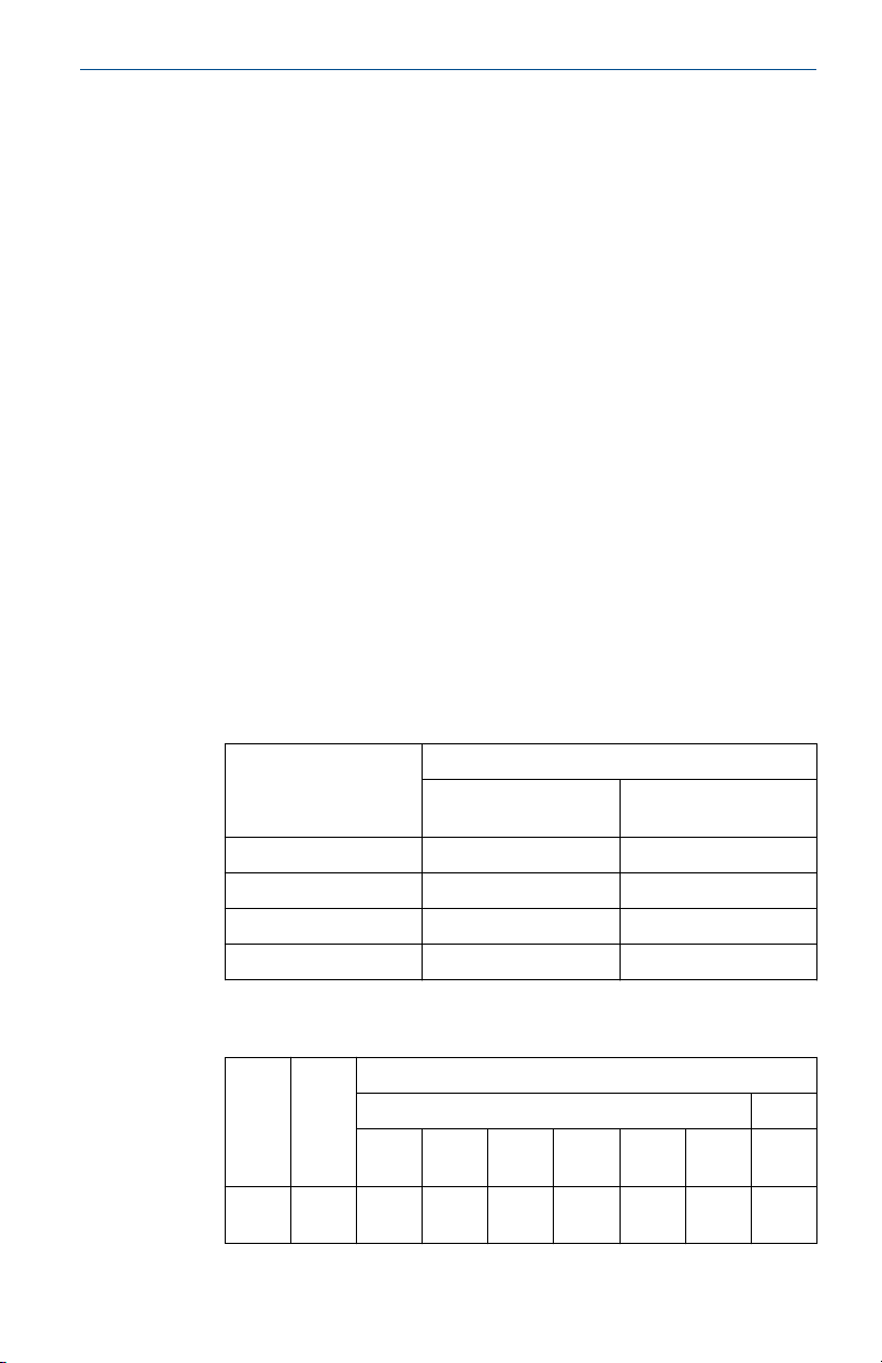
1. 产品温度组别和使用环境温度的关系为:
温度组别
T6 -50 ℃ ≤ Ta≤ +80 ℃ -50 ℃ ≤ Ta ≤ +80 ℃
T5 -50 ℃ ≤ Ta≤ +95 ℃ -50 ℃ ≤ Ta ≤ +95 ℃
T4~T1 -50 ℃ ≤ Ta≤ +100 ℃ -50 ℃ ≤ Ta ≤+95 ℃
T130 ℃ -50 ℃ ≤ Ta≤ +100 ℃ -50 ℃ ≤ Ta ≤+95 ℃
环境温度
AR1、SR1、AD1、
SD1、AT1、AJ1、AJ2
AR2、SR2
2. 产品温度组别和过程温度的关系为:
外壳
类型扩展长度
T6 T5 T4 T3 T2 T1 T130
AR2,
SR2无扩展
Quick Start Guide 17
55 70 95 95 95 95 95
过程温度(℃)
气体 粉尘
℃

Quick Start Guide May 2021
3’’ 55 70 100 100 100 100 100
6’’ 60 70 100 100 100 100 100
9’’ 65 75 110 110 110 110 110
AR1,
SR1,
AD1,
SD1,
AT1,
AJ1,
AJ2
任何
长度
85 100 135 200 300 450 130
3. 产品外壳设有接地端子,用户在使用时应可靠接地.
4. 安装现场应不存在对产品外壳有腐蚀作用的有害气体.
5. 现场安装时,电缆引入口须选用国家指定的防爆检验机构按检验认
可、具有 Ex d ⅡC Gb,Ex tD A21 IP6X 防爆等级的电缆引入装置或堵
封件,冗余电缆引入口须用堵封件有效密封.
6. 用于爆炸性气体环境中,现场安装、使用和维护必须严格遵守“断电
后开盖!”的警告语。用于爆炸性粉尘环境中,现场安装、使用和维
护必须严格遵守“爆炸性粉尘场所严禁开盖!”的警告语.
7. 用于爆炸性粉尘环境中,产品外壳表面需保持清洁,以防粉尘堆
积,但严禁用压缩空气吹扫.
8. 用户不得自行更换该产品的零部件,应会同产品制造商共同解决运
行中出现的故障,以杜绝损坏现象的发生.
9. 产品的安装、使用和维护应同时遵守产品使用说明书、
GB3836.13-2013“爆炸性环境 第 13 部分:设备的修理、检修、修
复和改造”、GB/T3836.15-2017“爆炸性环境 第 15 部分:电气装置
的设计、选型和安装”、GB/T3836.16-2017“爆炸性环境 第 16 部
分:电气装置的检查和维护”、GB50257-2014“电气装置安装工程爆
炸和火灾危险环境电力装置施工及验收规范”和 GB15577-2007“粉
尘防爆安全规程”的有关规定。
6.5.2 I3 China Intrinsic Safety
Certificate
Standards
Markings
18 Emerson.com/Rosemount
GYJ18.1024X (CCC 认证)
GB 3836.1-2010, GB 3836.4-2010, GB 3836.20-2010
Ex ia IIC T5/T6 Ga

May 2021 Quick Start Guide
产品安全使用特殊条件
证书编号后缀“X”表明产品具有安全使用特殊条件:产品必须安装于具有
IP20 外壳防护等级的外壳内方可使用.
产品使用注意事项
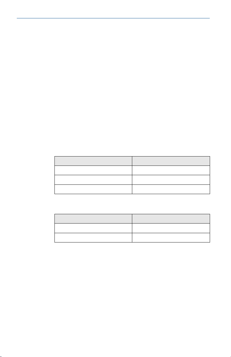
1. 产品使用环境温度和温度组别的关系为:
传感器类型 最大输入功率 Pi
热电偶 500 T6 -60 ℃ ~ +70 ℃
RTD 192 T6 -60 ℃ ~ +70 ℃
RTD 290 T6 -60 ℃ ~ +60 ℃
(mW)
2. 本安电气参数:
热电偶:
最高输入电压最大输入电流最大输入功
Ui (V) Ii (mA) Pi (mW) Ci (pF) Li (nH)
60 100 500 75 600
最高输出电压
Uo (V)
0.1 50 25
RTD:
最高输入电
压
Ui (V) Ii (mA) Pi (mW) Ci (pF) Li (nH)
60 100 192/290 75 600
最大输入电流最大输入功
率
最大输出电流
Io (mA)
率
温度组别 使用环境温度
T5 -60 ℃ ~ +70 ℃
最大内部等效参数
最大输出功率
Po (mW)
最大内部等效参数
3. 该产品必须与已通过防爆认证的关联设备配套共同组成本安防爆系
统方可使用于爆炸性气体环境。其系统接线必须同时遵守本产品和
所配关联设备的使用说明书要求,接线端子不得接错.
4. 用户不得自行更换该产品的零部件,应会同产品制造商共同解决运
行中出现的故障,以杜绝损坏现象的发生.
Quick Start Guide 19
Quick Start Guide May 2021
5. 产品的安装、使用和维护应同时遵守产品使用说明书、
GB3836.13-2013“爆炸性环境 第 13 部分:设备的修理、检修、修
复和改造”、GB3836.15-2000“爆炸性气体环境用电气设备 第 15 部
分:危险场所电气安装(煤矿除外)”、GB3836.16-2006“爆炸性气
体环境用电气设备 第 16 部分:电气装置的检查和维护(煤矿除
外)”、GB3836.18-2010“爆炸性环境 第 18 部分:本质安全系统”和
GB50257-2014“电气装置安装工程爆炸和火灾危险环境电力装置施
工及验收规范”的有关规定.
6.5.3 N3 China Zone 2
Certificate
Standards
Markings
GYJ18.1025 (CCC 认证)
GB 3836.1-2010, GB 3836.8-2014
Ex nA IIC T5 Gc, T5 (-40 °C ≤ Ta ≤ +70 °C)
产品使用注意事项
1. 产品使用环境温度为:-40 ℃~+70 ℃
2. 输入参数:
类型 输入参数 Ui
变送器 42.4 V
热电阻端子 5 V
热电偶端子 0 V
3. 产品外壳内可以安装如下温度变送器模块:
型号
644 系列 GYJ15.1502
248 系列 GYJ15.1089
防爆合格证编号
4. 现场安装时,电缆引入口须选用经国家指定的防爆检验机构检验认
可、具有 Ex e ⅡC Gb 或 Ex nR ⅡC Gc 防爆等级的电缆引入装置或堵封
件,冗余电缆引入口须用堵封件有效密封。电缆引入装置或封堵件
的安装使用必须遵守其使用说明书的要求并保证外壳防护等级达到
IP54 (符合 GB4208-2008 标准要求)以上.
5. 用户不得自行更换该产品的零部件,应会同产品制造商共同解决运
行中出现的故障,以杜绝损坏现象的发生.
6. 产品的安装、使用和维护应同时遵守产品使用说明书、
GB3836.13-2013“爆炸性环境 第 13 部分:设备的修理、检修、修
复和改造”、GB3836.15-2000“爆炸性气体环境用电气设备 第 15 部
20 Emerson.com/Rosemount

May 2021 Quick Start Guide
分:危险场所电气安装(煤矿除外)”、GB3836.16-2006“爆炸性气
体环境用电气设备 第 16 部分:电气装置的检查和维护(煤矿除
外)”和 GB50257-2014“电气装置安装工程爆炸和火灾危险环境电
力装置施工及验收规范”的有关规定.
6.6 Korea
6.6.1 EP Korea Flameproof
Certificate
Markings
Special Condition for Safe Use (X):
Refer to certificate for Special Conditions for Safe Use.
17-KA4BO-0305X
Ex d IIC T6…T1, T6 (-50 °C ≤ Ta ≤ +80 °C), T5 (-50 °C ≤ Ta ≤ +95
°C), T4…T1 (-50 °C ≤ Ta ≤ +100 °C)
6.6.2 IP Korea Intrinsic Safety
Certificate
Markings
Special Condition for Safe Use (X):
Refer to certificate for details regarding process and ambient temperature
limits as well as Special Conditions for Safe Use.
17-KA4BO-0304X
Ex ia IIC T6/T5
6.6.3 KP Korea Flameproof, Dust Ignitionproof, and Intrinsic Safety
Certificate
Markings
Special Condition for Safe Use (X):
Refer to certificate for details regarding process and ambient temperature
limits as well as Special Conditions for Safe Use.
17-KA4BO-0306X in addition to the EP and IP certificate
numbers
Ex tb IIIC T130 °C, T130 °C (-50 °C ≤ Ta ≤ +100 °C) in addition to
the markings for EP and IP
6.7
Russia
6.7.1 EM Technical Regulation Customs Union TR CU 012/2011 (EAC) Flameproof
Markings
Quick Start Guide 21
1Ex db IIC T6…T1 Gb X, T6 (–55 °C ≤ Ta ≤ +80 °C), T5 (–55 °C ≤
Ta ≤ +95 °C), T4…T1 (–55 °C ≤ Ta ≤ +100 °C)

Quick Start Guide May 2021
Special Condition for Safe Use (X):
Refer to certificate for Special Conditions for Safe Use.
6.7.2 IM Technical Regulation Customs Union TR CU 012/2011 (EAC) Intrinsic Safety
Markings
Special Condition for Safe Use (X):
Refer to certificate for details regarding process and ambient temperature
limits as well as Special Conditions for Safe Use.
0Ex ia IIC T5,T6 Ga X
6.7.3 KM Technical Regulation Customs Union TR CU 012/2011 (EAC) Flameproof, Dust-Ignitionproof, and Intrinsic Safety
Markings
Special Condition for Safe Use (X):
Refer to certificate for details regarding process and ambient temperature
limits as well as Special Conditions for Safe Use.
Ex tb IIIC T130 °C Db X in addition to the markings above for EM
and IM.
6.8 Combinations
K1
K3
K7
KA
KB
KC
KD
KE
KM
KN
KP
Combination of E1, I1, N1, and ND
Combination of E3, I3, and N3
Combination of E7, I7, N7, and NK
Combination of E1 and E6
Combination of E5 and E6
Combination of E1 and E5
Combination of E1, E5, and E6
Combination of E1, E5, E6, and E7
Combination of EM and IM
Combination of N1, N5, N6, and N7
Combination of EP and IP
22 Emerson.com/Rosemount

May 2021 Quick Start Guide
7 Declaration of Conformity
Quick Start Guide 23

Quick Start Guide May 2021
24 Emerson.com/Rosemount
214C
2/9/2021
ᴹ
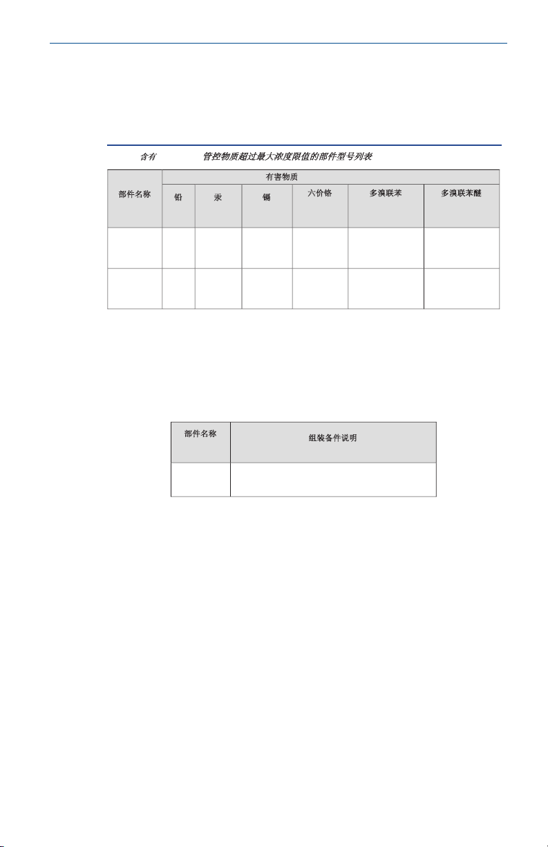
China RoHS
㇑᧗⢙䍘䎵䗷ᴰབྷ⎃ᓖ䲀٬Ⲵ䜘Ԧරࡇ㺘
214C Temperature Sensor
List of 214C Temperature Sensor Parts with China RoHS Concentration above MCVs
䜘Ԧ〠
Part Name
ᴹᇣ⢙䍘
/ Hazardous Substances
䫵
Lead
(Pb)
⊎
Mercury
(Hg)
䭹
Cadmium
(Cd)
ޝԧ䬜
Hexavalent
Chromium
(Cr +6)
ཊⓤ㚄㤟
Polybrominated
biphenyls
(PBB)
ཊⓤ㚄㤟䟊
Polybrominated
diphenyl ethers
(PBDE)
༣փ㓴Ԧ
Housing
Assembly
O O O O O O
Րᝏಘ㓴Ԧ
Sensor
Assembly
O O O O O O
ᵜ㺘Ṭ㌫ᦞ
SJ/T11364
Ⲵ㿴ᇊ㘼ࡦ
This table is proposed in accordance with the provision of SJ/T11364.
O:
Ѫ䈕䜘ԦⲴᡰᴹ൷䍘ᶀᯉѝ䈕ᴹᇣ⢙䍘Ⲵ䟿൷վҾ
GB/T 26572
ᡰ㿴ᇊⲴ䲀䟿㾱≲
O: Indicate that said hazardous substance in all of the homogeneous materials for this part is below the limit
requirement of GB/T 26572.
X:
Ѫ൘䈕䜘Ԧᡰ֯⭘Ⲵᡰᴹ൷䍘ᶀᯉ䟼ˈ㠣ቁᴹа㊫൷䍘ᶀᯉѝ䈕ᴹᇣ⢙䍘Ⲵ䟿儈Ҿ
GB/T 26572
ᡰ㿴ᇊⲴ䲀䟿㾱≲
X: Indicate that said hazardous substance contained in at least one of the homogeneous materials used for this part is
above the limit requirement of GB/T 26572.
䜘Ԧ〠
Part Name
㓴㻵༷Ԧ䈤᰾
Spare Parts Descriptions for Assemblies
༣փ㓴Ԧ
Housing
Assembly
⭥ᆀཆ༣Electrical Housing
May 2021 Quick Start Guide
8 China RoHS
Quick Start Guide 25

Quick Start Guide May 2021
26 Emerson.com/Rosemount

May 2021 Quick Start Guide
Quick Start Guide 27

*00825-0400-2654*
00825-0400-2654, Rev. DB
Quick Start Guide
May 2021
©
2021 Emerson. All rights reserved.
Emerson Terms and Conditions of Sale are
available upon request. The Emerson logo
is a trademark and service mark of
Emerson Electric Co. Rosemount is a mark
of one of the Emerson family of
companies. All other marks are the
property of their respective owners.
 Loading...