


LCD TV
Service Manual
Chassis MST9E19
Rolsen
RL-26B01
|
Contents |
|
Contents.................................................................................................................... |
2 |
|
1. |
Product Safety Servicing Guidelines ................................................................... |
3 |
2. |
Product Function Specifications.......................................................................... |
5 |
3. |
Lcd Panel Spec...................................................................................................... |
6 |
|
3-1 General Description................................................................................... |
6 |
4. |
Block Diagram ...................................................................................................... |
7 |
|
4-1 Main board ................................................................................................... |
7 |
|
4-2 Power board ............................................................................................... |
8 |
5. |
Service Mode And Adjustment ............................................................................ |
9 |
6. |
Software Updating ............................................................................................. |
13 |
|
6-1 Updating Tool .......................................................................................... |
13 |
|
6-2 Software Updating Operation................................................................. |
14 |
7. |
Troubleshooting ................................................................................................. |
24 |
8. |
Ciruit Diagram .................................................................................................... |
25 |
- 2 -
PDF created with pdfFactory Pro trial version www.pdffactory.com

1. Product Safety Servicing Guidelines
WARNING:
Service should not be attempted by anyone unfamiliar with the necessary precaution on this receiver. The following are the necessary precaution to be observed before serving this chassis.
1.Since the power supply circuit of this receiver is directly connected to the AC power line, an Isolation transformer should be used during any dynamic service to avoid possible shock hazard.
2.When replacing a chassis in the cabinet, always be certain that all the protective devices are put back in place, such as:
non-metallic control knobs, insulating cover, shields, isolation resistor-capacitor network etc.
3.When replacing parts or circuit boards, disconnect the power cord.
4.When replacing a high wattage resistor (oxide metal film resistor) on the circuit board, keep the resistor (1/2in) away from circuit board.
5.Connection wires must be kept away from components with high voltage or high temperature.
6.If any fuse in this LCD TV receiver is blown, replace it with the FUSE specified in the chassis part list.
The lightning flash with arrowhead symbol, within an equilateral triangle is intended to alert the user to the presence of
uninsulated dangerous voltage within the products enclosure that may be of sufficient magnitude to constitute a risk of electric shock.
The exclamation point within an equilateral triangle is intended to alert the user to the presence of important operating and
maintenance (servicing) instructions in the literature accompanying the set.
- 3 -
PDF created with pdfFactory Pro trial version www.pdffactory.com
Many electrical and mechanical parts in the chassis have special safety-related characteristics. These characteristics are often passed unnoticed by a visual inspection. When replacement parts are required, be sure the service technician uses replacement parts specified by us that have the same characteristics as the original part. Unauthorized substitutions may result in fire, electric shock and injury to persons or other hazards. This LCD TV product should be situated away from heat source such as radiation, stoves, or other product that produce heat.
- 4 -
PDF created with pdfFactory Pro trial version www.pdffactory.com
2 Product Function Specifications Refer to the User’s manual
- 5 -
PDF created with pdfFactory Pro trial version www.pdffactory.com
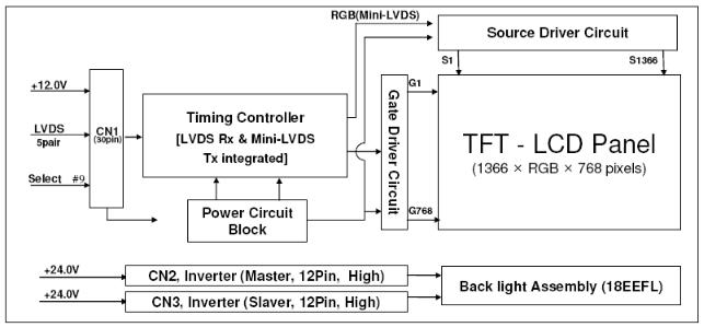
3. LCD Panel Spec
3-1 General Description
These Panel is a TFT LCD module supports 1366 x 768 WXGA format and can
display true 16.7M colors (8-bit colors).
- 6 -
PDF created with pdfFactory Pro trial version www.pdffactory.com
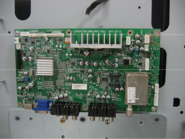
4. Block Diagram
4-1 Main board
1)26’’ and 32’’ with AV2 in/AV out interface
2) 26’’ and 32’’ with SCART interface
- 7 -
PDF created with pdfFactory Pro trial version www.pdffactory.com

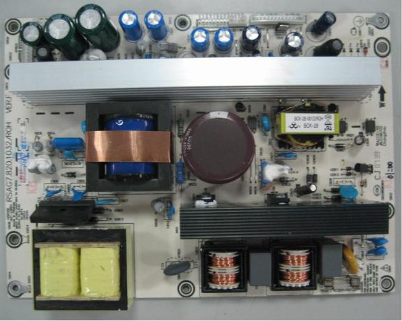
4-2 Power board
1) Power board of 26’’ and 32
2)Another Power board of 26’’ and 32
- 8 -
PDF created with pdfFactory Pro trial version www.pdffactory.com
5. Service Mode And Adjustment
LCD****: Use the remote control, first open MAIN MENU with MENU button, and choose PICTURE with the CHANNEL UP/DOWN button, then choose the Brightness with VOLUME UP, while Brightness value is 50, press 0 5 3 2,you can enter factory menu.
LCD****EU: Use the remote control, first open MAIN MENU with MENU button, and choose SOUND with the CHANNEL UP/DOWN button, then choose the Balance with VOLUME UP, while Balance value is 0, press 0 5 3 2,you can enter factory menu.
- 9 -
PDF created with pdfFactory Pro trial version www.pdffactory.com
 Loading...