

Page 1
Panoramakopf 200 Mark II
Panoramic Head 200 Mark II
360°
Panorama-
Aufnahmen
360°
panoramic
images
User Guide
for German and English
www.rollei.de
Page 2

Inhaltsverzeichnis
Einführung .............................................. 3
Hauptmerkmale | Verpackungsinhalt
1. Sicherheitshinweise .................................... 4
2. Produktbeschreibung .................................. 5
3. Voraussetzungen für ein gutes Panoramabild ............. 6
4. Den Panoramakopf aufbauen ........................... 7
5. Montage der Kamera ................................... 8
6. Positionierung des Nodalpunktes ....................... 11
6.1. Längspositionierung .................................. 12
6.2. Seitliche Positionierung ................................13
7. Anleitung für die Kugelpanoramafotografie .............14
8. Entsorgung ........................................... 16
8.1. Verpackung .........................................16
8.2. Gerät .............................................16
9. Spezifikationen ....................................... 17
DEUTSCH
Page 3

Liebe Kundin, lieber Kunde,
herzlichen Glückwunsch zum Kauf eines qualitativ hochwertigen Rollei Produktes.
Sie haben sich für den Panoramakopf mit guter technischer Ausstattung entschieden, der sich besonders einfach bedienen lässt. Bitte lesen Sie alle Hinweise
sorgfältig und aufmerksam. Beachten Sie besonders alle Sicherheitshinweise.
Auf das Gerät haben Sie zwei Jahre Garantie. Falls der Panoramakopf einmal
defekt sein sollte, benötigen Sie die beigefügte Garantiekarte und Ihren
Kaufbeleg.
Bewahren Sie diese zusammen mit der Bedienungsanleitung sorgfältig auf.
Fügen Sie die Bedienungsanleitung bei der Weitergabe an Dritte unbedingt bei.
Hinweis:
• Verwenden Sie den Panoramakopf nur für die vorgesehenen Zwecke. Wird
er für andere Zwecke verwendet und kommt es dadurch zu Schäden am
Gerät, so erlischt die Garantie. Zudem können nur bei bestimmungsgemäßer
Verwendung Schäden an Mensch und Umwelt ausgeschlossen werden.
Hauptmerkmale
• Präzise Aufnahme von Panorama-Sequenzen
• Mehrzeilige Panoramen sowie kubische VR-Fotos möglich
• Platzsparender Transport
Verpackungsinhalt
In der Verpackung befinden sich folgende Komponenten:
1. Rollei Panoramakopf 200 Mark II
2. Alu-Transportkoffer
3. Bedienungsanleitung
4. Garantiekarte
3
Page 4

4
1. Sicherheitshinweise
Gefahr für Kinder
• Halten Sie Kinder von Verpackungsmaterial fern. Es besteht u.a.
Erstickungsgefahr!
Vorsicht – Sachschäden
• Stellen Sie den Panoramakopf auf einen festen, ebenen Untergrund.
• Schützen Sie das Gerät vor Nässe, Staub, hohen Temperaturen und direkter
Sonneneinstrahlung. Andernfalls kann es zu Schäden kommen.
• Halten Sie ausreichend Abstand zu Wärmequellen wie z.B. Herdplatten oder
Öfen.
• Lassen Sie den Panoramakopf nicht fallen und setzen Sie ihn keinen starken
Stößen aus.
• Stellen Sie keine Kerzen oder andere offene Brandquellen in die Nähe des
Panoramakopfes.
• Verwenden Sie zum Reinigen keine scharfen Chemikalien, aggressive oder
scheuernde Reinigungsmittel.
DEUTSCH
Page 5
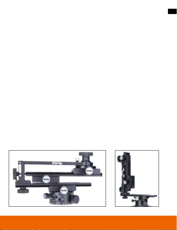
2. Produktbeschreibung
Der Rollei Panoramakopf 200 Mark II ist ein Mehrzeilen-Panoramakopf. Er hat
Gleitteller zum Aufsetzen der Kamera auf der Drehachse des Panoramakopfes,
sowie eine Gleitplatte, die sich um die Achse herum nach vorn / nach hinten
dreht. Diese Neigung ermöglicht es, die Kamera / das Objektiv vom „Nodalpunkt“ aus (Punkt der Achse eines zentrierten Systems) in der horizontalen und
vertikalen Achse zu drehen. Auf diese Weise können mühelos und mit Präzision
Sequenzen von mehrzeiligen Panoramen aufgenommen werden (kubische VRFotos sowie vollständig sichtbares 360º-Panoramabild).
Mit der Verwendung des Panoramakopfes wird der Einsatz von Verbindungssoftware für Bilder in VR-Umgebung sowohl in der Nachbearbeitung als auch
in der Korrektur minimiert, und man erhält auf diese Weise eine perfekte Komposition. Alle Gleitschienen und Drehführungen haben klare Skalen, die nach
Festlegung des Nodalpunktes eine einfache Positionsänderung der Kamera
ermöglichen.
Die Vertikalhalterung des Panoramakopfes kann gelöst, um 90° gedreht und
wieder befestigt werden, um platzsparend transportiert zu werden. Zudem sind
dadurch die Gleitmechanismen gegen Stöße, Schläge und Aufprall geschützt.
5
Page 6

6
3. Voraussetzungen für ein gutes Panoramabild
Der Panoramakopf wurde so entwickelt, dass er das Erstellen virtueller Szenen
mit dem Computer über verschiedene Sequenzen von Digitalfotos oder
digitalisierten Fotos ermöglicht, die von verschiedenen vertikalen Winkeln aus
eingefangen werden.
Für eine gute Panoramasequenz sind vier Grundvoraussetzungen erforderlich:
1. Eine präzise Nivellierung der Panoramaachse.
2. Ein Panoramakopf, der Ihnen die Wahl des Rotationswinkels zwischen einer
Aufnahme und der nächsten ermöglicht.
3. Die Möglichkeit, die Kamera so anzubringen, dass der Nodalpunkt der
kristallinen Linse (Frontlinse des Objektivs) exakt über der Panorama-Drehachse liegt, und auf diese Weise Parallaxenfehler zwischen den nahen und
fernen Objekten in der Szene vermieden werden.
4. Eine zusätzliche Drehachse, die es ermöglicht, verschiedene Panoramasequenzen in unterschiedlichen vertikalen Winkeln so aufzunehmen, dass sich
ein komplettes Kugelbild ergibt.
Der Panoramakopf besteht aus drei Hauptmodulen, die die oben genannten
Funktionen ausführen, und ihre Schienen sind mit Libellen (Wasserwagen)
ausgestattet.
DEUTSCH
Page 7
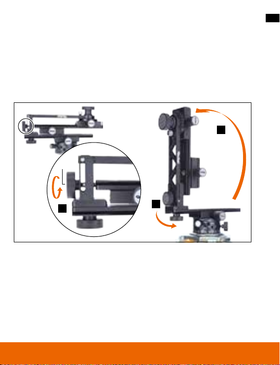
4. Den Panoramakopf aufbauen
Montieren Sie den Panoramakopf über das 3/8“ Gewinde an der Basisplatte
Ihres Stativs.
Entfernen Sie nun Knopf „A“ komplett (siehe 1 in Abb. 1) und drehen die
Halterung in die vertikale Position (2). Fixieren Sie die Halterung indem Sie die
Schraube in das dafür vorgesehene Gewinde einschrauben.
2
A
7
Abb. 1
1
3
Page 8
8
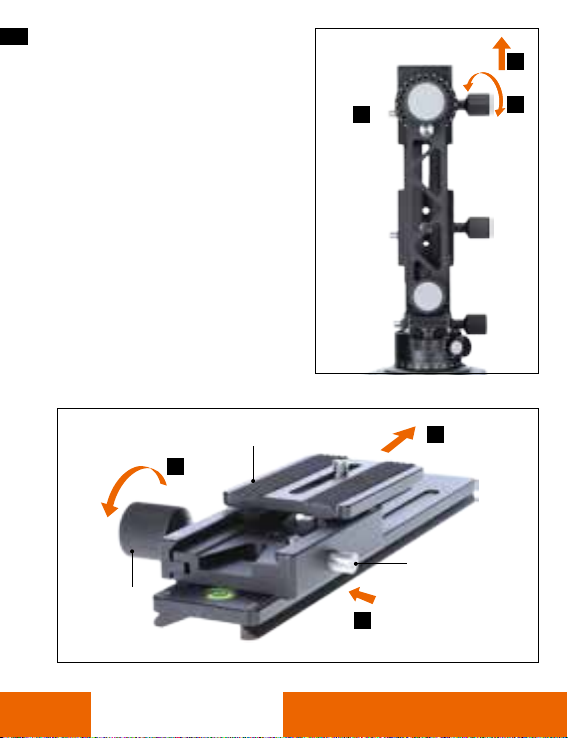
5. Montage der Kamera
Um die obere Schiene des Panoramakopfes abzunehmen, lösen Sie
zunächst die Fixierung „D“ (siehe 1 in
Abb. 2). Ziehen Sie die Schiene bis zum
Anschlag heraus und drücken dann
den Sicherungsknopf „E“ (2), um sie
ganz zu entfernen (3).
Lösen Sie die Sicherungsschraube „G“
(siehe 1 in Abb. 3) und drücken dann
den Sicherungsknopf „H“ (2), um
die Basisplatte der Kamera „CP“ zu
entnehmen (3).
Abb. 2
3
1
2
E
D
Abb. 3
G
DEUTSCH
CP
1
2
3
H
Page 9
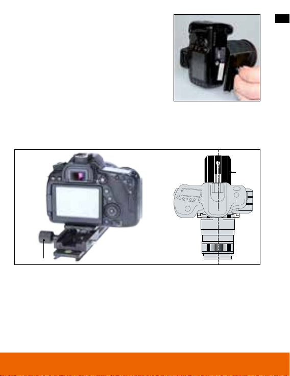
5. Montage der Kamera
In der Schnellwechselplatte befindet sich eine
1/4“-Schraube, die zum Be festigen der Kamera
dient (siehe Abb. 4).
Montieren Sie nun die Kamera mit der Befestigungsplatte auf der Gleitschiene wie in Abb. 5
dargestellt. Achten Sie d arauf, dass der Mittelpunkt der Linse auf den Mittelpunkt der Platte
ausgerichtet ist.
G
Bevor die Grundplatte wieder auf den Panoramakopf aufgesetzt wird, prüfen
Sie die Ausrichtung der Kamera zur Grundplatte. Die Achse der Linse und
die Mittelachse der Grundplatte müssen wie in Abb. 5 gezeigt perfekt übereinstimmen.
Abb. 4
Abb. 5
F
9
Page 10
10
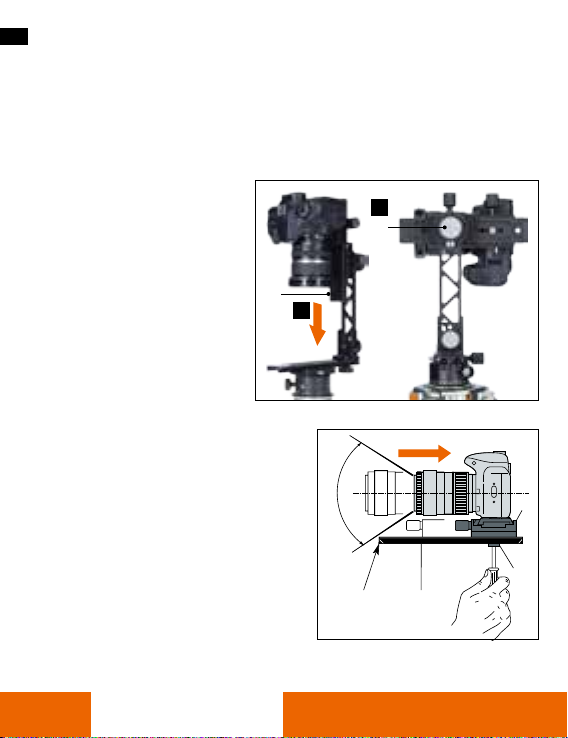
5. Montage der Kamera
Die mit den Platten verbundene Kamera setzen Sie nun mit dem Objektiv nach
unten in den Panoramakopf ein (siehe Abb. 6). Schieben Sie die Gleitschiene
über den Widerstand der Sicherheitsverriegelung hinweg in die gewünschte
Position und fixieren sie die Schiene durch die seitliche Schraube.
Um die Kamera in die verti-
kale Ebene zu bringen, lösen
Sie die Schraube „W“ auf
der Rückseite (siehe Abb. 6),
schwenken die Kamera in die
gewünschte Ausrichtung und
fixieren diese Position durch
Andrehen der Schraube „W“.
Die Position des Einschubs „M” zur
Schiene „F” ist wie folgt einzustellen:
Schraube „O” lösen und den Einschub
die Schiene entlanggleiten lassen. Die
ideale Position ist, den Kamerakörper
auf der Schiene „N” so weit hinten wie
möglich aufzusetzen, da der Einschub
„F” so positioniert sein muss, dass
diese Schiene nicht in das Sichtfeld der
Kamera „P” gerät.
F
1
2
W
Abb. 6
P
N F
Abb. 7
M
O
DEUTSCH
Page 11
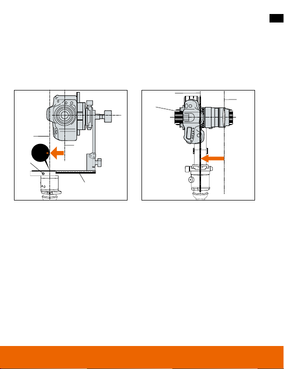
6. Positionierung des Nodalpunktes
Um die optische Achse „Q“ der Kamera (siehe Abb. 8) zur Panorama-Drehachse
„R“ im Stativ-Mittelpunkt (center) auszurichten, lösen Sie die Schraube der
Skalenschiene „S“, bringen die Kamera in die entsprechende Position und
fixieren die Schraube wieder.
11
Abb. 8
U
F
T
R
Center
Q
V
S
Abb. 9
Die Längsebene der Kamera wird wie folgt ausgerichtet (siehe Abb. 9): Lösen
Sie die Schraube der Grundplatte „F“ und schieben die Kamera so in Position,
dass die Achse der Frontlinse „T“ der Kamera mit der Panorama-Drehachse
„U“ des Stativ-Mittelpunkts übereinstimmt. Fixieren Sie die Schraube der
Grundplatte dann wieder.
Von diesem Moment an ermöglicht Ihnen diese Ausrichtung bereits die Planung
von Landschafts- und Außenaufnahmen.
Wenn die zu fotografierende Umgebung Objekte in verschiedenen Ebenen oder
Abständen vom Bilderfassungspunkt enthält, muss der Nodalpunkt korrigiert
werden (diese Vorgehensweise ist nur mit Reflexkameras möglich).
Page 12

12
6. Positionierung des Nodalpunktes
6.1 Längspositionierung
Wählen Sie eine Ebene, die ein nahes Objekt „1” und ein fernes Objekt „2”
enthält, die sich aber in der gleichen Sichtausrichtung in vertikaler Richtung
befinden (Abb. 10).
1. Lösen Sie Knopf „W“ und drehen die Kamera vertikal, so dass die beiden
Objekte „1“ und „2“ zuerst im Bild nach oben und danach nach unten gebracht werden. Stellen Sie so fest, ob die Höhendifferenz „Y“ zwischen den
beiden Objekten von einem Foto zum anderen verschieden ist. Je konstanter
der Abstand ist, desto besser ist der Nodalpunkt eingestellt (siehe Abb. 11
und 12).
2. Um bessere Resultate zu erzielen, verändern Sie die Einstellung in kleinen
Schritten durch Bewegung der Grundplatte „F“. Wenn die korrekte Position
erreicht wurde, so sollte diese von der Gradskala der Platte „F“ notiert
werden.
Abb. 11Abb. 10
2
Y
W
1
F
Abb. 12
Y
1
2
1
2
DEUTSCH
Page 13

6. Positionierung des Nodalpunktes
6.2 Seitliche Positionierung
Wählen Sie eine Ebene, die ein nahes Objekt „1” und ein fernes Objekt „2” in
der gleichen Sichtausrichtung in horizontaler Richtung enthält (Abb. 13).
1. Lösen Sie die Fixierung der Basis (Lock), um die Kamera um die Panoramaachse
herum zu bewegen. Richten Sie die Kamera so aus, dass die beiden Bezugsobjekte zuerst auf der linken Seite des Bildes erscheinen und danach auf der
rechten Seite (siehe Abb. 14 und 15). Stellen Sie so fest, ob der horizontale
Abstand „X“ zwischen den beiden Objekten auf den beiden aufgenommenen
Fotos voneinander abweicht: Je konstanter dieser Abstand ist, desto genauer
ist die seitliche Positionierung des Nodalpunktes.
2. Um bessere Resultate zu erzielen, verändern Sie die Einstellung in kleinen
Schritten durch Bewegung der Grundplatte „S“. Wenn die korrekte Position erreicht wurde, so sollte diese von der Gradskala der Platte „S“ notiert werden.
Hinweis: Führen Sie zuerst immer die Einstellung der Längspositionierung
aus. Stellen Sie die seitliche Positionierung erst dann ein, wenn die Längspositionierung definiert ist.
Abb. 13 Abb.
2
1
S
AF
14
Abb.
15
X
2
1
X
2
1
13
Page 14

14
7. Anleitung für die Kugelpanoramafotografie
Ein besonderes Bild erhält man durch Verknüpfen verschiedener, in unterschiedlichen horizontalen Winkeln aufgenommener Panoramasequenzen.
Zuerst ist die Anzahl der Sequenzen zu definieren, die zum Komplettieren der
Kugel notwendig sind. Diese Anzahl hängt von dem verwendeten Linsenwinkel in Verbindung mit der Änderung des Kopfes (Wahl von Schritten von
15°/24°/60° und 90°) ab. Vor Beginn der Panoramasequenz ist mit Hilfe der
runden Gradskala „Z“ (siehe Abb. 16) der vertikale Ausgangswinkel auszuwählen. Die Schraube „AA“ muss dabei gelöst bzw. ganz entfernt werden.
Abb. 16
Z
W
Y
Fixierschraube Y
AD
AC
AB
AA
DEUTSCH
Page 15

7. Anleitung für die Kugelpanoramafotografie
Legen Sie die Anzahl der Aufnahmen oder Drehschritte (15°/ 24°/6 0° o der 90°)
zwischen jeder Auslösung für die erste Panoramasequenz fest (siehe Tabelle).
Winkel 90° 60° 45° 36° 30° 24° 20° 15° 10° 5°
Anz. Aufnahmen 4 6 8 10 12 15 18 24 36 72
• Entsprechend der gewählten Konfiguration die Schrauben in die Löcher
„AC” oder „AD” einsetzen.
• Die Kamera auf der oberen Platte in die Ausgangsposition drehen
(erstes Auslösen einer Aufnahme).
• Die Kamera in der Ausgangsposition fixieren und die Mitteltrommel drehen,
bis erster „click stop“ erreicht ist, mit Knopf „AA” verriegeln.
• Erste Aufnahme auslösen und danach die Kamera bis zum nächsten „click
stop” drehen, ohne den Knopf „AA” zu entriegeln.
Auf diese Weise weiter verfahren, bis die erste Panoramasequenz fertig ist (bis
zum Erreichen der 360°-Ausgangsposition).
Nach dem Abschluss der ersten Panoramasequenz können Sie weitere Sequenzen
beginnen, die zum Erfassen der Sphäre notwendig sind: Ändern Sie den vertikalen
Winkel (Höhenwinkel) mit Hilfe von Knopf „W” und der runden Gradskala „Z” und
wiederholen Sie die oben beschriebenen Vorgänge für jede komplette Sequenz.
An der Basis des Kopfes „AD” befindet sich eine Gradskala „AE”, die von 0º
bis 360º geht, und eine Markierung auf der Mittelsäule. Diese Daten müssen als
Bezugswert zum Bestimmen der Winkel verwendet werden.
Um den Kopf auf diese Weise zu verwenden, ist Knopf „AA” zu entriegeln,
damit der „click stop” während der Drehung der Mittelsäule gelöst wird. Jetzt
mit Knopf „W“ und „Y“ die Auslöseposition verriegeln.
15
Page 16

16
8. Entsorgung
8.1 Verpackung
8.2 Gerät
Die Produktverpackung besteht aus recyclingfähigen Materialien und
kann dem Wertstoffkreislauf zugeführt werden. Entsorgen Sie diese
umweltgerecht.
Wenn das Gerät einmal ausgedient hat, muss das Gerät entsprechend
EG-Richtlinie 2002/96/EG einer geordneten Entsorgung zugeführt
werden und darf keinesfalls über den normalen Hausmüll entsorgt
werden. Führen Sie Altgeräte einer Sammelstelle für Elektroschrott zu.
Dort werden im Gerät enthaltene Wertstoffe der Wiederverwertung
zugeführt und damit eine Belastung der Umwelt vermieden. Wenden
Sie sich für nähere Auskünfte an Ihr örtliches Entsorgungsunternehmen oder an Ihre kommunale Verwaltung.
DEUTSCH
Page 17

9. Spezifikationen
Technische Daten
Gewicht
Material
Stativkopf-Steuerung
Rastschritte Rotation
Max. Traglast
Maße (zusammengeklappt)
Kameraanschluss
Stativanschluss
Lieferumfang
Änderungen von Design und technischen Daten bleiben vorbehalten und bedürfen keiner Ankündigung.
1171 g
Aluminium
360°
4x90° | 6x60° | 15x24° | 24x15°
3 kg
22 x 14 x 8,7 cm
1/4“ Schraubengewinde
3/8“ Gewinde
Panoramakopf, Transportkoffer
17
Page 18

Table of Contents
Introduction ............................................ 19
Key Features | Package Contents
1. Safety instructions .................................... 20
2. Product description ................................... 21
3. Requirements for a good panoramic picture ............. 22
4. Assembly of the panorama head .......................23
5. Mounting the camera ................................. 24
6. Positioning of the nodal point .........................27
6.1. Longitudinal positioning ............................... 28
6.2. Lateral positioning ...................................29
7. Instructions for spherical panoramic photography ....... 30
8. Disposal ............................................. 32
8.1. Packaging .......................................... 32
8.2. Device ............................................. 32
9. Specifications ........................................ 33
ENGLISH
Page 19

Dear Customer,
Congratulation on purchasing a high quality Rollei product.You have opted
for the panorama head with great technical equipment, which is particularly
simple to operate. Please read all the instructions carefully and thouroughly.
Pay particular attention to all safety instructions.
You have a two year warranty on the device. If the panoramic head should
malfunction, you will need the enclosed warranty card and your receipt. Store
them carefully with the operating instructions. When passing the device on to a
third party, be sure to include the instruction manual.
Note:
• Use the panorama head only for the intendend purposes. If it is used for
other purposes and the device is damaged in the process, the warranty will
become void. More importantly, personal injury and environment damage
can only be excluded when used for the intended purpose.
Key features
• Accurate capture of panoramic sequences
• Multi-line panoramas and cubic VR photos possible
• Space saving transportation
Package contents
In the package you will find the following components:
1. Rollei Panoramic Head 200 Mark II
2. Aluminium-carrying case
3. User manual
4. Warranty card
19
Page 20

20
1. Safety instructions
Danger for children
• Keep children away from packaging risks include danger of suffocation!
Caution – damage to property
• Place the panorama head on a firm, level surface.
• Protect the device from moisture, dust, high temperatures and direct
sunlight. Not doing so may cause damage.
• Maintain a sucient distance from heat sources such as stove tops or ovens.
• Do not drop the panorama head and do not subject it to any severe impacts.
• Do not candles or any other open ames near to the panorama head.
• Do not use any harsh chemicals, corrosive or abrasive cleaners for cleaning
purposes.
ENGLISH
Page 21

2. Product description
The Rollei Panoramic Head 200 Mark II is a multi-row panorama head. It has a
sliding plate for placing the camera on the rotating axis of the panorama head
and a sliding plate which rotates backwards and forwards around the axis.
This tilting action makes it possible to rotate the camera/lens from the “nodal
point” (point of axis of a centred system) in the horizontal and vertical axes. In
this way, sequences of multi-line panoramas can be taken effortlessly and with
precision (cubic VR photos as well as fully visible 360º panoramic images).
With the multi-row use of connectivity software for images in a VR environment is minimised both in post processing and in correction, and this results in
a perfect composition.
All the slide rails and rotation guides have clear scales that enable the position
of the camera to be changed easily after setting the nodal point.
The vertical mounting of the multi-row can be released, turned through 90°
and re-tightened, in order to save space in transit. This also ensures that the
sliding mechanisms are protected from shocks, blows and impacts.
21
Page 22

22
3. Requirements for a good panoramic image
The panorama head was developed to enable the creation of virtual scenes
with a computer by means of various sequences of digital photos or digitised
photos, which are captured from various vertical angles.
For a good panoramic sequence, four basic requirements are necessary:
1. Precise levelling of the panoramic axis.
2. A panorama head that gives you the choice of rotation angle between one
frame and the next.
3. The ability to mount the camera so that the nodal point of the crystalline
lens (front lens) lies exactly above the panoramic rotation axis and in this
way parallax errors between near and distant objects in the scene are
avoided.
4. An additional rotational axis that makes it possible to capture various
panorama sequences from different vertical angles resulting in a complete
spherical image.
The panorama head consists of three main modules which perform the above
functions, and their guide rails are equipped with spirit levels.
ENGLISH
Page 23

4. Assembly of the panorama head
Attach the panoramic head onto the base plate of your tripod by using the
3/8“ thread.
Now completely remove knob ”A“ (see 1 in Fig. 1) and rotate the bracket into
the vertical position (2). Secure the bracket by screwing the knob into the
thread.
2
A
23
Fig. 1
1
3
Page 24

24
5. Mounting the camera
To remove the upper rail of the
panorama head, first loosen the fixing
knob “D” (see1 in Fig. 2). Pull the rail
out until it stops and then push the
locking button “E” (2) to remove it
completely (3).
Loosen the locking screw ”G“
(see 1 in Fig. 3) and then push the
locking button ”H“ (2), to remove the
camera base plate ”CP“ (3).
Fig. 2
3
1
2
E
D
Fig. 3
G
ENGLISH
CP
1
2
3
H
Page 25

5. Mounting the camera
The quick release plate has a 1/4“ screw to
attach it to the camera (see Fig.4).
Now attach the camera with the mounting plate
onto the slide rail as shown in Fig. 5. Make sure
that the centre of the lens is lined up with centre
of the plate.
G
Before the base plate is put back onto the panorama head check the align ment
of the camera relation to the base plate. The axis of lens and the central axis of
the base plate must match perfectly as shown in Fig 5.
Fig. 4
Fig. 5
F
25
Page 26

26
5. Mounting the camera
Now place the camera attached to the plates into panorama head with the
lens pointing downwards (see Fig. 6). Push the slide rail past the resistance of
the saftey lock into the desired positions and secure the rail using the screw
the side.
To positions the camera in
the vertical plane loosen
screw ”W“ on the back (see
Fig 6). Pivot the camera to
the desired alignment and fix
it in this position by
tightening screw ”W“.
The position of mount ”M“ on rail
“F” is adjusted as follows loosen:
Screw “O” and slide the mount along
the rail. The ideal positioning is to place
the camera bidy on the rail ”N“ as far
back as possible, as the mount at ”F“
must be in such a position
that this rail does not appear in the
camera´s field of view ”P“.
F
1
2
W
Fig. 6
P
N F
Fig. 7
M
O
ENGLISH
Page 27

6. Positioning of the nodal point
In order to algin the camera´s optical axis ”Q“ in relation to the panorama
rotating axis ”R“ in the tripod´s centre, loosen the screw on scale rail ”S“,
move the camera into the appropriate position and retighten the screw.
27
Fig. 8
U
F
T
R
Center
Q
V
S
Fig. 9
The longitudinal plane of the camera is aligned as follows (see Fig. 9). Loosen
the screw on the base plate ”F“ and slide the camera into position, so that the
axis of the camera´s front lens ”T“ aligns with the panoramic rotating axis ”U“
of the tripod´s centre. Then tighten the base plate screw again.
From this moment on this aligment enables you to plan scenic and outdoor
photography.
If the environment to be photograhed contains objects in different planes or
at different distances from the image capture point, the nodal point must be
corrected (this procedure is only possible with reflex cameras).
Page 28

28
6. Positioning of the nodal point
6.1 Longitudinal positioning
Select plane that contains a near object ”1“ and a distant object ”2“ wich are
also situated in the same visual orientation in a vertical direction (Fig.10).
1. Loosen knob ”W“ and rotate the camera vertically so that both objects ”1“
and ”2“ appear first at the top and then at the bottom of the shot. Check
whether the height difference ”Y“ between the two objects is different from
one photo to another. The more consistent the distance is the better the
nodal point is set (see Fig. 11 and 12).
2. To achieve better results modify the adjustment in small increments by
moving the base plate ”F“. When the correct position has been reached, it
should be noted from the scale on plate.
Fig. 11Fig. 10
2
Y
W
1
F
Fig. 12
Y
1
2
1
2
ENGLISH
Page 29

6. Positioning of the nodal point
6.2 Lateral positioning
Select a plane that contains a near object ”1“ and a distant object ”2“ in the
same visual orientation, in a horizontal direction (Fig. 13).
1. Loosen the base fixture (lock) in order to move the camera about the
panoramic axis. Align the camera so that both reference objects appear first
on the left hand side and then on the right hand side of the shot (see Fig.
14 and 15). Check whether the horizontal distance ”X“ between the two
objects differs in the two photos taken: The more constant this distance is,
the more precise the lateral positioning of the nodal point is.
2. To achieve better results modify the adjustment in small increments by
moving the base plate ”S“. When the correct position has been reached, it
should be noted from the scale on plate ”S“.
Note: Always carry out the adjustment of the longitudinal positioning first. Do not
adjust the lateral positioning until the longitudinal positioning has been defined.
29
Fig. 13 Fig.
2
1
S
AF
14
Fig.
15
X
2
1
X
2
1
Page 30

30
7. Instructions for spherical panorama photography
A special image can be achieved by combining various panorama sequences
taken at different horizontal angles. First of all number of sequences necessary
to complete the sphere must be defined. This number depends on the lens
angle used in conjunction with the adjustment of the head (choice of
15°/24°/60° and 90° increments).
Before beginning the panorama sequence the vertical exit angle is to be chosen
with the aid of the round scale ”Z“ (Fig. 16). At the same time the ”AA“ screw
must be loosened or removed entirely.
Abb. 16
Z
W
Y
Fixing screw Y
AD
AC
AB
AA
ENGLISH
Page 31

7. Instructions for spherical panorama photography
Set the number of shots or rotary steps (15°, 24°, 60° or 90°) between each
shutter for the first panorama sequence (see table below).
Angle 90° 60° 45° 36° 30° 24° 20° 15° 10° 5°
No. of shots 4 6 8 10 12 15 18 24 36 72
• Depending on the chosen configuration, insert the screws in hole ”AC“ or
”AD“.
• Rotate the camera on the top plate to the starting position (first shutter
release of a shot).
• Fix the camera in the starting position and rotate the central drum until the
first ”click stop“ is reached, lock with knob „AA“.
• Trigger the first shot and then rotate the camera to the next “click stop”
without unlocking knob ”AA“.
Proceed in this way until the first panorama sequence is finished (until reaching
the 360° starting position).
After the completion of the first panorama sequence you can begin the further
sequences necassary to complete the sphere: Modify the vertical angle (elevation angle) with the help of knob ”W“ and the round scale ”Z“ and repeat
the processes outlined above for each complete sequence.
On the base of the head ”AD“ is a graduated scale ”AE“, wich goes from 0° to
360°, and a mark on the central column. This data must be used as a reference
value to determine the angle. To use the head in this way, the knob ”AA“ must
be unlocked so that the ”click stop“ is disengaged during the rotation of the
central column. Now lock the shutter release position with knob ”W“ and ”Y”.
31
Page 32

32
8. Disposal
8.1 Packaging
The product packaging is made from recycable materials and can be
ureturned to the resource cycle. Dispose of it in an environmentally
friendly way.
8.2 Device
When the device has eventually worn out it must be disposed of
properly according to EC directive 2002/96/EC and must under no
circumstances be disposed of with normal household waste. Take
old equipment to a collection point for electrical equipment. There,
substances contained in the device can be taken for recycling and
thus prevent contamination of the environment. For further information please contact your local waste disposal company or your
local council.
ENGLISH
Page 33

9. Specifications
Technical Features
Weight
Material
Panoramic head control
Rotation steps
Max. load
Size (folded)
Camera connection
Tripod connection
Scope of delivery
Subject to technical changes.
33
1171 g
Aluminum
360°
4x90° | 6x60° | 15x24° | 24x15°
3 kg
22 x 14 x 8.7 cm
1/4“ screw
3/8“ thread
Panoramic head, sturdy carrying case
Page 34

Panoramakopf 200 Mark II
Panoramic Head 200 Mark II
www.rollei.com
Page 35

ARCA
SWISS
kompatibel /
compatible
Page 36

Distribution
Rollei GmbH & Co. KG
In de Tarpen 42
D-22848 Norderstedt
Service Hotline
+49 40 270750270
Return Service:
Rollei Service Germany
Denisstraße 28a
67663 Kaiserslautern
www.rollei.de/social
www.rollei.com/social
www.rollei.com
 Loading...