

Roland udk20 User Manual

Double Sheet Detector
R1000 series UDK20
Electro magnetic and eddy current principles
integrated in one sensor microcontroller based
Only one linearized sensor for ferrous and non-ferrous materials
FE materials for sheet thickness up to max. 4 mm (.16 in.)
NF materials for sheet thickness up to max. 4 mm (.16 in.) depending on electrical conductivity
• Direct connection of up to 2 sensors to a unit possible (version 2 PW)
• Programmable for 255 different sheet thicknesses and materials
• Calibration with a teach-in procedure
• Digital display of sheet thickness and operational parameters
• Monitoring of over-gauge and under-gauge limits
• Monitoring of operating voltage and sensor
• Galvanically insulated 9-bit PLC input interface
• Galvanically insulated 4-bit PLC output interface
• Selectable equipment interfaces:
- Data communication and data backup via (optional) potential-free RS232 interface
- Relay outputs or opto-coupler outputs for under-gauge, nominal gauge, over-gauge and enabling
ROLAND
DOUBLE SHEET CONTROL UDK20
> Panel mount enclosure
> All common fieldbus standards
NOW AVAILABLE:

© 2006 Roland Electronic GmbH.
All rights on this document are at Roland Electronic GmbH.
Reproduction (also partly), electronical coverage,
translation, transmission to third parties,
only with our prior permission.
Subject to change without further notice.

ROLAND
OPERATING INSTRUCTIONS
DOUBLE SHEET DETECTOR R1000 UDK20
Rev. 1.0 Page 3
ROLAND ELECTRONIC GMBH · Otto-Maurer-Str. 17 · D-75210 Keltern · Telefon (0049) (0 7236) 93 92-0 · Telefax (0049) (0 7236) 93 92-33
Declaration of conformity according to EC directives
Manufacturer: Roland Electronic GmbH · Otto-Maurer-Str. 17 · DE 75210 Keltern
Product Name: Double Sheet Detector
Product Type: R1000 UDK20
Roland Electronic GmbH declares that the product above complies with the requirements of the ECC
directives for harmonizing the legal code within the member states.
The conformity with the directives of the product listed above is confirmed by complying fully with the
harmonized European comply standards below.
89/336/ECC: Directive regarding emission standard;
modified by Directive RL 91/263/ECC, 92/31/ECC and 93/68/ECC.
EN61000-6-4: 2001 EN61000-6-2: 2001
Year of apposition of CE mark: 2006
Keltern, 01.09.2006 Managing Director
..................................................................................................................................................................
Place, Date Signature Function of the signer
The declaration confirms the compliance with the cited directives. However, it is not any implied warranty of fitness for a
particular purpose especially as it may relate to product liability.
The safety instructions and warnings must be observed.
DIN EN ISO 9001 / Reg.-Nr. 5152

ROLAND
OPERATING INSTRUCTIONS
DOUBLE SHEET DETECTOR R1000 UDK20
Page 4 B0048991
ROLAND ELECTRONIC GMBH · Otto-Maurer-Str. 17 · D-75210 Keltern · Telefon (0049) (07236) 93 92-0 · Telefax (0049) (0 7236) 93 92-33
Blank page

ROLAND
OPERATING INSTRUCTIONS
DOUBLE SHEET DETECTOR R1000 UDK20
Page 5
ROLAND ELECTRONIC GMBH · Otto-Maurer-Str. 17 · D-75210 Keltern · Telefon (0049) (0 7236) 93 92-0 · Telefax (0049) (0 7236) 93 92-33
Rev. 1.0 / 08.11.2006
Table of Contents
Declaration of conformity according to EC directives ................................................................ Page3
1. Safety instructions and warnings for user ............................................................................ Page9
1.1 Intented use ..................................................................................................................... Page9
2. Technical data ........................................................................................................................ Page11
2.1 Sensors .......................................................................................................................... Page11
2.2 Sensor performance data for ferrous (FE) materials ...................................................... Page12
2.3 Sensor data for non-ferrous (FE) material ...................................................................... Page14
2.4 Versions of the control unit UDK20 ................................................................................ Page15
2.5 Technical data control unit UDK20 ................................................................................. Page16
2.6 Technical data SSBUDK10 (Sensor switch box) ............................................................ Page17
2.7 Sensor Cables ............................................................................................................... Page17
3. System description ............................................................................................................... Page19
3.1 General hints for process security ................................................................................. Page19
3.2 Control unit..................................................................................................................... Page20
3.3 Parameters of the control unit ........................................................................................ Page20
3.3.1 System parameters: .......................................................................................... Page21
3.3.2 Program parameters .......................................................................................... Page23
3.4 Typical Application examples ......................................................................................... Page25
4. Mounting ................................................................................................................................Page31
4.1 General mounting instructions ....................................................................................... Page31
4.2 Dimensions of the enclosure .......................................................................................... Page32
4.3 Sensor mounting ............................................................................................................ Page35
4.3.1 Spring loaded sensor bracket SHS42G-FB (with bellow suction cup) ................ Page36
4.3.2 Spring loaded sensor bracket SHS42GS (with flat suction cup) ........................ Page37
4.3.3 Spring loaded sensor bracket SH42GS ............................................................. Page39
4.3.4 Clamping device SHK ........................................................................................ Page40
4.3.5 Incorrect installation of the PW sensors ............................................................ Page41
4.3.6 Electromagnetic interference ............................................................................. Page41
4.4 Mounting of the Sensor Switch Box SSBUDK10 ........................................................... Page42
5. Electrical installation ............................................................................................................ Page43
5.1 General instructions ....................................................................................................... Page43
5.2 Allocation of connections ............................................................................................... Page44
5.2.1 Sensor connection - 1st sensor ......................................................................... Page46
5.2.2 Sensor connection - 2nd sensor ........................................................................ Page47
5.2.3 Connection of Sensor Switch Box (SSB) .......................................................... Page48
5.2.4 Connection of RS232 ......................................................................................... Page48
5.2.5 Central connection (central plug) ....................................................................... Page49
5.2.5.1 Machine grounding ............................................................................................. Page49
5.2.5.2 Supply voltage ................................................................................................... Page49
5.2.5.3 Data inputs / outputs to PLC ............................................................................. Page50
5.2.6 Connection of the PW42GS sensor and the sensor cable ................................. Page54
5.2.7 Cable SVCPWS-SSBUDK10 ............................................................................. Page55

ROLAND
OPERATING INSTRUCTIONS
DOUBLE SHEET DETECTOR R1000 UDK20
Page 6 B0048991
ROLAND ELECTRONIC GMBH · Otto-Maurer-Str. 17 · D-75210 Keltern · Telefon (0049) (07236) 93 92-0 · Telefax (0049) (0 7236) 93 92-33
5.3 Connection diagrams ..................................................................................................... Page56
5.3.1 UDK20-XX-S-XX with one PW42AGS sensor ................................................... Page56
5.3.2 UDK20XX-S-XX with SSBUDK10 and four PW42AGS sensors ........................ Page57
5.3.3 UDK20-2PW-XX-S-XX with two PW42AGS sensors ......................................... Page58
5.4 Internal wiring of the Sensor Switch Box SSBUDK10 .................................................... Page59
6. Communication with the PLC .............................................................................................. Page61
6.1 External control .............................................................................................................. Page61
6.1.1 System test ....................................................................................................... Page62
6.1.2 Measurement menue selection .......................................................................... Page63
6.1.3 Measurement Start / Stop ................................................................................. Page65
6.1.3.1 Single measurement .......................................................................................... Page65
6.1.3.2 Continuous measurement .................................................................................. Page67
6.1.4 External zero adjust (via PLC inputs) ................................................................ Page69
6.1.5 External Teach-in (via PLC inputs) ..................................................................... Page70
6.1.6 Typical measuring cycle when using the unit for destacking ............................. Page71
7. Start-up ................................................................................................................................... Page73
7.1 Initial Start-up ................................................................................................................ Page73
7.2 Operation ....................................................................................................................... Page74
7.3 Configuration menu ........................................................................................................ Page75
7.4 General information regarding configuration ................................................................... Page76
7.5 Changing, adjusting or checking the configuration ......................................................... Page76
7.6 System parameters ........................................................................................................ Page77
7.7 Program parameters ...................................................................................................... Page84
7.7.1 Program parameter 7: Zero adjust .................................................................... Page86
7.7.2 Program parameter 8: Teach-in ......................................................................... Page87
7.8 Data backup via serial RS232-interface (only for C-versions) ........................................ Page90
8. Operation ............................................................................................................................... Page91
8.1 Abbreviated operating instructions ................................................................................. Page91
8.2 Entering a new measurement program ........................................................................... Page93
9. Fault messages, causes and remedies ................................................................................ Page95
9.1 Fault messages of the Sensor Switch Box .................................................................... Page96
9.2 Memory faults (faults no. 1 to 24)................................................................................... Page97
9.3 Zero adjust faults (fault no. 25 to 29).............................................................................. Page98
9.4 Teach-in fault (faults no. 30 to 39) .................................................................................. Page98
9.5 RS232 Transmission faults (faults no. 40 to 49) ............................................................. Page98
9.6 Faults due to measuring operation (faults no. 50 to 54) .................................................. Page99
9.7 Keyboard faults (fault no. 55 to 59) ................................................................................. Page99
9.8 Faults due to operating voltage (faults no. 60 to 64) ....................................................... Page99
9.9 Sensor Switch Box faults (faults no. 65 to 69) ............................................................... Page99
9.10 Faults parallel PLC inputs (faults no. 70 to 79) ............................................................. Page100
9.11 Other faults (80 to XX) ................................................................................................. Page100

ROLAND
OPERATING INSTRUCTIONS
DOUBLE SHEET DETECTOR R1000 UDK20
Page 7
ROLAND ELECTRONIC GMBH · Otto-Maurer-Str. 17 · D-75210 Keltern · Telefon (0049) (0 7236) 93 92-0 · Telefax (0049) (0 7236) 93 92-33
Rev. 1.0 / 08.11.2006
10. Maintenance......................................................................................................................... Page101
10.1 Sensor exchange ......................................................................................................... Page101
10.2 Exchange of a Control unit ........................................................................................... Page102
10.3 Exchange of the fuses ................................................................................................. Page103
10.4 Data back up via serial interface (only for C-version units) .......................................... Page103
10.5 RPP-XP software (WinXP version) .............................................................................. Page104
10.6 Spare parts .................................................................................................................. Page107
11. Technical information ......................................................................................................... Page109
11.1 Exchange of a R1000 UDK10 control unit against a R1000 UDK20 control unit .......... Page109
11.2 System configuration ................................................................................................... Page109
12. Order data ............................................................................................................................ Page110
12.1 Versions of UDK20....................................................................................................... Page110
12.2 System accessories .................................................................................................... Page110
12.3 Sensors and accessories ............................................................................................. Page111
12.4 Cables .......................................................................................................................... Page111
12.5 Cable plugs and cable sockets .................................................................................... Page112
12.6 Other accessories ........................................................................................................ Page112

ROLAND
OPERATING INSTRUCTIONS
DOUBLE SHEET DETECTOR R1000 UDK20
Page 8 B0048991
ROLAND ELECTRONIC GMBH · Otto-Maurer-Str. 17 · D-75210 Keltern · Telefon (0049) (07236) 93 92-0 · Telefax (0049) (0 7236) 93 92-33
Blank page

ROLAND
OPERATING INSTRUCTIONS
DOUBLE SHEET DETECTOR R1000 UDK20
Rev. 1.0 Page 9
ROLAND ELECTRONIC GMBH · Otto-Maurer-Str. 17 · D-75210 Keltern · Telefon (0049) (0 7236) 93 92-0 · Telefax (0049) (0 7236) 93 92-33
1. Safety instructions and warnings for user
This handbook contains all necessary information for the correct operation of the R1000 family of systems.
It is intended for usage by technically qualified personnel.
Unauthorized tampering with the unit, especially ignoring the warnings in these operating instructions, can
cause malfunction and damage to the unit.
Only authorized personnel may perform changes to the unit and make cable connections (especially the power
supply).
Should measurements within the unit be required (e.g. for service or repair), then all customary accident
prevention procedures must be observed. Only professional electrical tools should be used.
Note: Factory system adjustments, especially the upper and lower limits, are made
to provide optimal machine protection. Deviations from factory adjustments could
impair the protection.
1.1 Intented use
Flexible manufacturing systems in the sheet processing industry require reliable Double Sheet Control
systems, in order to protect presses and other sheet processing machines against damage caused by
feeding multiple sheets.
The Double Sheet Detector R1000 UDK20 was specifically developed for this technical environment.
Depending on the application (type of material, thickness, sensor gap) the UDK20 can be used with one or
more sensors. The reliable function of the Double Sheet Detector depends therefore markedly on the
selection of the correct sensors and the mounting of the sensors.

ROLAND
OPERATING INSTRUCTIONS
DOUBLE SHEET DETECTOR R1000 UDK20
Page 10 B0048991
ROLAND ELECTRONIC GMBH · Otto-Maurer-Str. 17 · D-75210 Keltern · Telefon (0049) (07236) 93 92-0 · Telefax (0049) (0 7236) 93 92-33
Blank page

ROLAND
OPERATING INSTRUCTIONS
DOUBLE SHEET DETECTOR R1000 UDK20
Rev. 1.0 Page 11
ROLAND ELECTRONIC GMBH · Otto-Maurer-Str. 17 · D-75210 Keltern · Telefon (0049) (0 7236) 93 92-0 · Telefax (0049) (0 7236) 93 92-33
2. Technical data
2.1 Sensors
The sensor description has the following code:
Picture: Sensor description
Sensor PW42AGS
PW42AGS PW42AGSPW42AGS
All dimensions are in mm
Tolerance ± 0.15mm
Measure with free space for connecting plug to sensor
Picture: Sensor dimensions PW42AGS
Ambient temperature: 0 - 60 °C (32 - 140 °F)
Weight: 0.45 kg (1 lb)
Protection category: IP65
PW42AGS
electro
magnet
eddy
current
diameter threaded
body
quick
disconnect
version
ROLAND
OPERATING INSTRUCTIONS
DOUBLE SHEET DETECTOR R1000 UDK20
Page 12 B0048991
ROLAND ELECTRONIC GMBH · Otto-Maurer-Str. 17 · D-75210 Keltern · Telefon (0049) (07236) 93 92-0 · Telefax (0049) (0 7236) 93 92-33
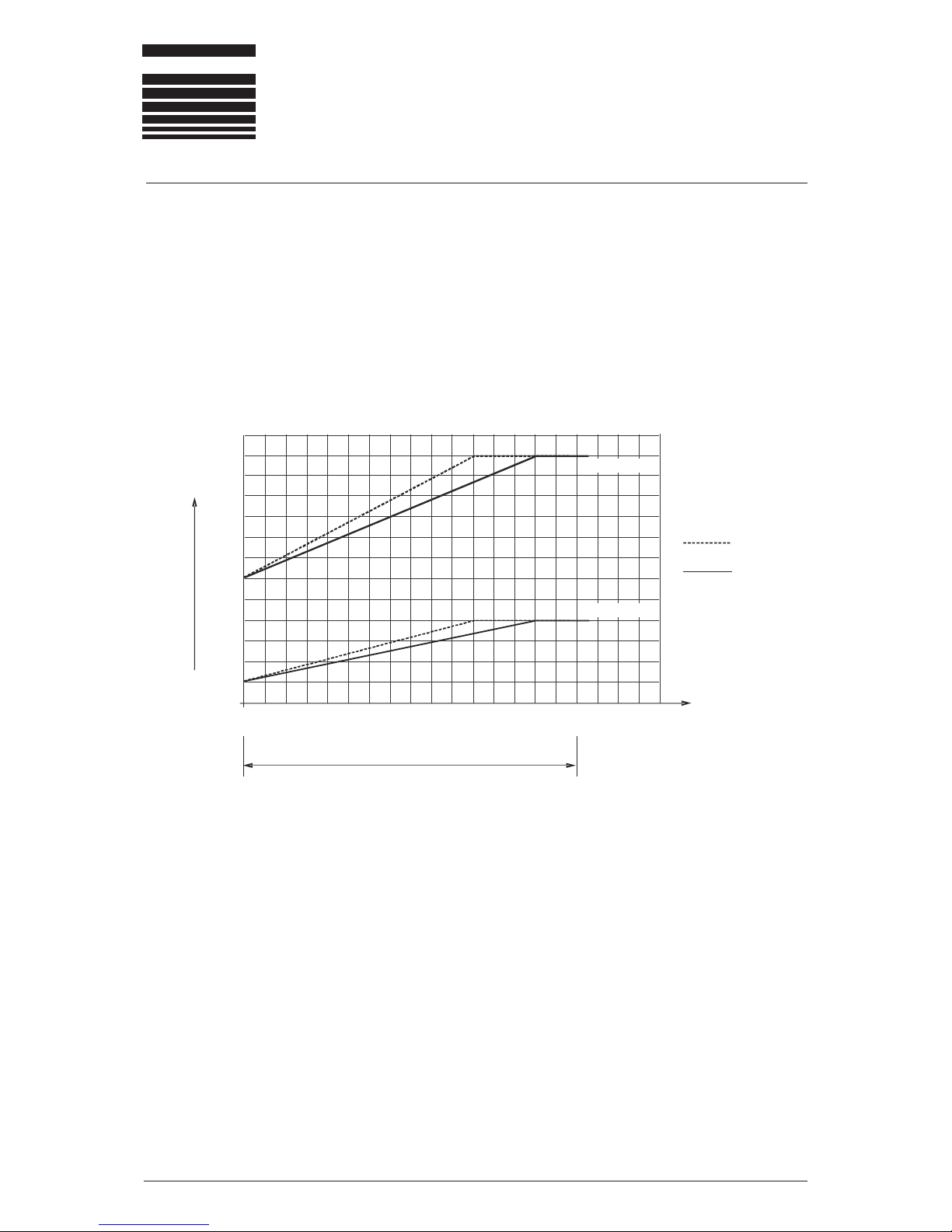
2.2 Sensor performance data for ferrous (FE) materials
The following diagram shows the reaction time of the system on detecting double sheet, depending on the
nominal sheet thickness and the selected upper switching limit (UL) 150% or 120%.
Example: Nominal thickness 1.5 mm = 100% (.06 in. = 100%), measurement with 1 sensor.
The maximum system reaction time for detecting the exceeding of the double sheet threshold is 63 ms at
120% UL. This means, it takes 63 milliseconds after having recognized the measurement start signal until
the result is available at the output.
The data for 2 sensors apply in the so-called sequencer mode.
40
50
60
70
80
90
100
110
120
130
140
150
160
170
4,0 Single sheet thickness
(nominal thickness) [mm]
Normal working range
(0 to .16 inch)
3,53,02,52,01,51,00,50
System reaction time [ms]
150%
120%
PW42AGS
2 sensors
1 sensor
Picture: System reaction time for ferrous material
Double sheet thresholds above 120% reduce the performance of the system with regard to air gaps between
the sheets and increase the systems reaction time according to the diagram.
Air gaps influence the performance negatively because air has - in contrast to steel - a high resistance to
the magnetic flux. Therefore, air gaps reduce the performance of the system considerably
(see chapter 3.1 “Measuring principle and conditions influencing measurement accuray“).
For reliable double sheet monitoring there must not be any air gap between sheet and sensor as well as no
air gap between the sheets. This aspect has to be considered when mounting the sensors and selecting
the place of installation. The influence of air gaps can be read from the following diagrams.

ROLAND
OPERATING INSTRUCTIONS
DOUBLE SHEET DETECTOR R1000 UDK20
Rev. 1.0 Page 13
ROLAND ELECTRONIC GMBH · Otto-Maurer-Str. 17 · D-75210 Keltern · Telefon (0049) (0 7236) 93 92-0 · Telefax (0049) (0 7236) 93 92-33
Max. air gap between sensor and 1st sheet (1st gap)
0,2
0,4
0,6
1,4
1,6
1,8
2,0
2,2
0,0
1st air gap [mm]
0,8
1,0
1,2
PW42AGS
0,0 0,5 1,0 1,5 2,0 2,5 3,0 3,5 4,0 4,5 5,0
Sheet thickness
[mm]
Max. air gap between 1st and 2nd sheet (2nd gap)
0,0 0,5 1,0 1,5 2,0 2,5 3,0 3,5 4,0 4,5 5,0 Sheet thickness
[mm]
1,0
2,0
3,0
4,0
5,0
6,0
7,0
8,0
9,0
0,0
2nd air gap [mm]
PW42AGS
1.
2.

ROLAND
OPERATING INSTRUCTIONS
DOUBLE SHEET DETECTOR R1000 UDK20
Page 14 B0048991
ROLAND ELECTRONIC GMBH · Otto-Maurer-Str. 17 · D-75210 Keltern · Telefon (0049) (07236) 93 92-0 · Telefax (0049) (0 7236) 93 92-33
2.3 Sensor data for non-ferrous (FE) material
The amount of eddy current generated and the corresponding energy absorption is directly related to the
electrical conductivity. High values of electrical conductivity and the corresponding strong eddy currents
reduce the controllable sheet thickness.
The eddy current principle is more forgiving with regard to air gaps than the electromagnetic principle.
However, for most reliable performance precaution should be taken to avoid air gaps between sensor and
sheet. The permissible air gaps between first and second sheet can be slightly higher than for steel.
Note: The system reaction time for non-ferrous materials is constant at 85
milliseconds. This applies for measurements with 1 sensor as well as for measurements
with 2 sensors (in sequencer mode).
Material Conductivity
(MS)
Max. thickness
f. single sheet
(mm)
Austenite 1,41 4,0
Bronze 8,5 4,0
Zinc 16,3 4,0
AL-Alloy 18,2 4,0
AL-Alloy 25,2 4,0
AL 34,2 4,0
CU-Alloy 43,0 3,5
CU 57,5 3,0
Table: Max. sheet thickness for non-ferrous material (selection)
ROLAND
OPERATING INSTRUCTIONS
DOUBLE SHEET DETECTOR R1000 UDK20
Rev. 1.0 Page 15
ROLAND ELECTRONIC GMBH · Otto-Maurer-Str. 17 · D-75210 Keltern · Telefon (0049) (0 7236) 93 92-0 · Telefax (0049) (0 7236) 93 92-33
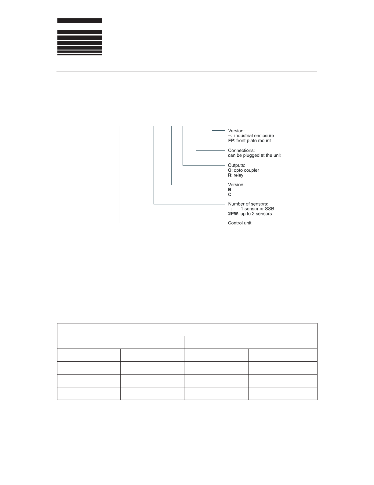
2.4 Versions of the control unit UDK20
The product designation is coded as follows :
UDK20-xxx-x-x-S-xx
Version B: Memory for 255 Parameter sets (nominal thicknesses and upper and lower limit values).
Programming via pushbuttons.
Adressing via 9 potential free control inputs 24 VDC with common potential.
Version C: As version B, but additionally:
1 potential free RS232 interface for data backup.
From the code shown above the following versions of the control unit will result. All versions are available.
)selpmaxe(tinulortnoc02KDUehtfosnoisreV
)BSSaiv4.xam(rosnes1htiw srosnes2otpuhtiw
erusolcnelairtsudninitn
uometalptnorfroferusolcnelairtsudninitnuometalptnorfrof
S-R-B-02KDUPF-S-R-B-02KDUS-R-B-WP2-02KDUPF-S-R-B-WP
2-02KDU
S-O-B-02KDUPF-S-O-B-02KDUS-O-B-WP2-02KDUPF-S-O-B-WP2-02KDU
S-O-C-02KDUPF-S-O-C-02KDUS-O-C-WP2-02KDUPF
-S-O-C-WP2-02KDU

ROLAND
OPERATING INSTRUCTIONS
DOUBLE SHEET DETECTOR R1000 UDK20
Page 16 B0048991
ROLAND ELECTRONIC GMBH · Otto-Maurer-Str. 17 · D-75210 Keltern · Telefon (0049) (07236) 93 92-0 · Telefax (0049) (0 7236) 93 92-33
2.5 Technical data control unit UDK20
Operating voltage: 24 VDC, +6V / -2 V
Power consumption: < 60 W (measuring mode < 60 W, standby mode < 10 W)
Switch on current: approx.: 10 A for 1 ms
External Fuse: 5 A, slow-blow
Weight: approx.: 1.2 kg (2.65 lb)
Ambient temperature: 0 - 50 °C (32 - 122 °F)
Wall mount enclosure
Dimensions (without connected plugs): approx.: 205 x 140 x 80 mm (L x W x H)
approx.: 8.07 x 5.51 x 3.15 inch (L x W x H)
Dimensions (with PG connected plugs): approx.: 205 x 220 x 80 mm (L x W x H)
approx.: 8.07 x 8.66 x 3.15 inch (L x W x H)
Protection category: IP65
Front panel enclosure
Dimensions: approx.: 180 x 180 x 70 mm (L x W x H)
approx.: 7.09 x 7.09 x 2.76 inch (L x W x H)
Protection category: IP40 (inside), IP65 (front cover)
Additional characteristics
• 255 parameter sets memory
• Programming via push buttons
• 9 galvanically insulated optocoupler inputs 24 VDC with joint common
Specification:
- min. switching voltage HIGH: 18 VDC
- max. switching voltage HIGH: 30 VDC
- min. switching voltage LOW: 0 VDC
- max. switching voltage LOW: 8 VDC
• 4 potential free outputs with common positive supply voltage
Specification:
Relais version:
- switching outputs: potential free relay opening contacts
- max. switching voltage: 250 V AC
- max. switching current: 1 A
- max. switching capacity: 240 W / 200 VA
Opto coupler version:
- switching outputs: emitter and collektor open
- max. switching voltage: 50 VDC
- max. switching current: 150 mA
- max. switching capacity: 100 mW
Attention: With inductive load please use unloading diodes. Otherwise the signal output can be
damaged by voltage surges caused by switching off inductive loads.

ROLAND
OPERATING INSTRUCTIONS
DOUBLE SHEET DETECTOR R1000 UDK20
Rev. 1.0 Page 17
ROLAND ELECTRONIC GMBH · Otto-Maurer-Str. 17 · D-75210 Keltern · Telefon (0049) (0 7236) 93 92-0 · Telefax (0049) (0 7236) 93 92-33
• RS232 interface
Specification:
- Baudrate: 4800
- Data Bits: 8
- Parity-Bit: None
- Stop-Bit: 1
- Hardware Handshake: None
2.6 Technical data SSBUDK10 (Sensor switch box)
Operating voltage: 24 VDC, supplied from the UDK20 control unit
Power consumption: < 10 W
Protection category: IP65
Weight: 1.4 kg (3 lb)
Ambient temperature: 0 - 50 °C (32 - 122 °F)
2.7 Sensor Cables
Cable types:
SCPWS-GG, SCPWS-GW: Superflex-C (Y) PURKOMBI 2 x 1 mm2 + 4 x 2 x 0,25 mm2, Lütze Company
Specification:
The selected cables have the following properties:
• Drag chain suitable
• Oil resistant
• PUR-cable sheath
• DIN color code
• Tinned copper shield
For more information please refer to specifications of Lütze Company representations in your country.

ROLAND
OPERATING INSTRUCTIONS
DOUBLE SHEET DETECTOR R1000 UDK20
Page 18 B0048991
ROLAND ELECTRONIC GMBH · Otto-Maurer-Str. 17 · D-75210 Keltern · Telefon (0049) (07236) 93 92-0 · Telefax (0049) (0 7236) 93 92-33
Blank page

OPERATING INSTRUCTIONS
DOUBLE SHEET DETECTOR R1000 UDK20
Rev. 1.0 Page 19
ROLAND ELECTRONIC GMBH · Otto-Maurer-Str. 17 · D-75210 Keltern · Telefon (0049) (0 7236) 93 92-0 · Telefax (0049) (0 7236) 93 92-33
ROLAND
3. System description
Flexible manufacturing systems in sheet metal processing require automated and reliable double sheet
control systems in order to safeguard presses and other processing machinery against damage due to
multiple sheets. This applies not only to steel but also to aluminum and other non-ferrous metals as well
as non-magnetic stainless-steel (austenite), materials as they are increasingly being used in automotive
applications. In addition, the production of so-called “Tailor Welded Blanks“ (TWB) has created complex
manufacturing systems with special requirements regarding automated double sheet control systems.
The Double Sheet Detector UDK20 was specifically developed for this technical environment. The special
feature of the system is the ability to monitor ferrous and non-ferrous materials with one sensor only - the
PW42AGS.
A system for one measuring point consists of the following three components:
• Control unit
• Sensor PW42AGS for ferrous and non-ferrous materials
• Sensor cable
3.1 General hints for process security
The process security of the system is influenced by the following factors:
• the stability of the measuring values
• the setting of under-gauge threshold and over-gauge threshold
• the evaluation of the status signals
Stable measuring conditions will result in stable measuring results. For measuring procedures with singlesided contacting sensors the air gap between sensor and material surface is a decisive criterion.
Air gaps varying from measurement to measurement will cause varying mesuring results. Basically, such
situations are bad, since in such cases the user is inclined to decrease the under-gauge threshold and to
increase the over-gauge threshold. On doing so, the user puts up with the drastically increasing risk of not
detecting a double sheet.
The following external factors decisively influence the stability of measuring results and need to be
considered for operation of a double sheet detector:
• the air gap between sensor and material surface
• the electrical and magnetical characteristics of the material
• the tolerance in material thickness
From this some simple rules derive, which enable a large degree of process security when abided by:
• Always care for good contact of the sensor with the material !
• Use the same program to monitor materials of the same thickness and alloy !
• Adjust the switching threshold as tight as possible !

ROLAND
OPERATING INSTRUCTIONS
DOUBLE SHEET DETECTOR R1000 UDK20
Page 20 B0048991
ROLAND ELECTRONIC GMBH · Otto-Maurer-Str. 17 · D-75210 Keltern · Telefon (0049) (07236) 93 92-0 · Telefax (0049) (0 7236) 93 92-33
Furthermore it is necessary that the control checks all status signals of the UDK20. The 0-sheet signal also
needs to be checked. While measuring, only the 1-sheet signal may occur. If 0-sheet or 2-sheet occurs,
the measured sheet may not be transported on. In such cases, the sheet will usually be deposited, re-picked
and measured again.
• The control needs to evaluate all status signals !
Checking-up through the 0-sheet signal is to assure that a sheet really is in front of the sensor during
measuring. If 0-sheet occurs while measuring, the measurement is not correct. For example, a defective
sensor holder might prevent the sensor from contacting the sheet. Monitoring the sheet thickness would
then only be performed apparently. In case of double sheet fatal consequences could then result.
3.2 Control unit
The UDK20 is based on the product platform R1000.
Major features of the control unit:
• Programmable for 255 different sheet thickness and materials
• Calibration by teaching procedures
• Digital display of sheet thickness and operating parameters
• Monitoring of over- gauge and under- gauge limits
• Monitoring of operating voltage and sensor cable (for broken wire)
• Optocoupler for direct I/O control via the PLC for fast measurement operations
• Data storage via serial interface
3.3 Parameters of the control unit
The UDK20 provides for extensive configuration. So, different customer requirements can be served.
Configuration is performed by setting system parameters and program parameters. System parameters are
set only once on commissioning, and will then remain unchanged. Program parameters contain items which
are material and job depending, and enable individual adaptation to the measuring task.

OPERATING INSTRUCTIONS
DOUBLE SHEET DETECTOR R1000 UDK20
Rev. 1.0 Page 21
ROLAND ELECTRONIC GMBH · Otto-Maurer-Str. 17 · D-75210 Keltern · Telefon (0049) (0 7236) 93 92-0 · Telefax (0049) (0 7236) 93 92-33
ROLAND
3.3.1 System parameters:
“Language“
System languages available for operating the unit via display and keyboard:
German / English / Spanish / Italian / French.
“Sensor type“
At the time of editing the sensor type PW42A is available. For this sensor a characteristical curve for
linearization purposes exists.
“Number of sensors“
Defines the number of connected sensors. Those sensors are then available for measuring. At a 2channel unit (UDK20-2PW...) max. 2 sensors can be connected, at a 1-channel system with sensorswitch-box max. 4 sensors can be connected.
“Indication in“
Switches the indication of the thickness values on the display between mm <=> inch.
“Measurement operation“
Sets how the measuring is to be triggered. The following modes are available:
• Demo
The demo mode is only intended for test and demonstration purposes. In this mode mesauring is
performed until the demo mode is switched off again. For doing so, another mode must be
selected. The repetition time of the measuring is 1 second for FE material, for NE and LM
material it is below 0.085 seconds.
• Ext. Single (default setting)
Here a single measuring is performed. For doing so, the signal “Measuring start“ must be
externally fed. Another measuring requires a new flank of the “Measuring start“ signal.
• Ext. Permanently
Here the measuring is maintained as long as the signal “Measuring start“ is fed. The repetition
time of the measuring is 0.5 seconds for FE material, for NE and LM material it is below 0.085
seconds.
“FE Measuring fast/normal“
For time-critical applications the measuring time can be slightly shortened for measuring FE material. If
“fast“ is selected and double sheet occurs, the measuring is terminated on reaching the upper switch
limit, and the information “2-sheet“ is released. If “normal“ is selected, the measuring will be executed
to the end and the measured thickness will be displayed.
“FE-T-limit“
On teaching-in of FE material the deviation of the measured thickness from the nominal thickness will
be monitored. Certain ferro magnetical materials show larger deviations as usual. In these cases the
33%/142% setting makes sense. Default setting is 66%/125%. Both values represent the permitted
relative range of measured to nominal thickness. If the measuring value is not within this range, the
teach-in cannot be performed and will be aborted with an error message.

ROLAND
OPERATING INSTRUCTIONS
DOUBLE SHEET DETECTOR R1000 UDK20
Page 22 B0048991
ROLAND ELECTRONIC GMBH · Otto-Maurer-Str. 17 · D-75210 Keltern · Telefon (0049) (07236) 93 92-0 · Telefax (0049) (0 7236) 93 92-33
“CLR parameter (Clear Program Parameter)“
Deletes all program parameters. For doing so, the parameter needs to be set to “yes“. Executing the
command requires several minutes, since the program memory will completely cleared. All program
parameters will be reset to the default values and existing teach-in data will be deleted. Using this
function only makes sense if a unit is to be newly used for another machine.
“Password yes/no“
Switches the password request on/off. If the password request is set “on“, the system / program
parameters can only be changed after the password has been entered.
“External Alignment“
Sets whether an external teach-in / zero adjust is to be possible. If “yes“ is set, the PLC can trigger the
procedure via the inputs “Teach-In 0-, 1-sheet“. Default setting is “no“.
• The external alignment may only be performed under supervision of an operator.
“Output level“
Sets the output voltages for outputs 0-,1-,2-sheet führen. Default setting is 0 V DC.
“Diagnosis factor“
Diagnosis of the factors located during the Teach-In. No default setting.
“W-Diagnosis“
Diagnosis of the measuring values for NF material type. No default setting.
“UDK20-PR-S-(1)“
“SV:xx HV:xx“
Identification of unit. Needs to be at hand for telephone support.
“Version“
Indication of the version of the unit. Factory setting, do not change !

OPERATING INSTRUCTIONS
DOUBLE SHEET DETECTOR R1000 UDK20
Rev. 1.0 Page 23
ROLAND ELECTRONIC GMBH · Otto-Maurer-Str. 17 · D-75210 Keltern · Telefon (0049) (0 7236) 93 92-0 · Telefax (0049) (0 7236) 93 92-33
ROLAND
3.3.2 Program parameters
The sensor is operated in two different modes. For FE material an electro magnetical method – called
“P“ measurement – is used. For the P measurement a compensation curve for linearization exists. The
compensation curve fits to ST37 steel. Other steel alloys resp. magnetical materials deviate from this
curve. This causes measuring results which can deviate for more than 5% from the real sheet
thickness. In such cases it is useful to calibrate the unit (later merely called “Teach-In“).
For NF material an eddy current method – called “W“ measurement – is applied. Here a Teach-In is
required, since there is no general linearization curve.
In order to avoid frequent Teach-In procedures for different materials and thicknesses, the unit provides
for 255 program memories. Every such memory consists of a data set with the following parameters.
“Sensor number“
For multi-channel systems (e.g. UDK20-2PW…) or a system with external sensor switch box SSBUDK10 the selected sensor must be entered.
“Material“
Selects the material type FE, NF or LM (slightly magnetical stainless steels). In case of unknown
material AUTO must be chosen. For all settings (except for FE) a Teach-in is required.
“Nominal measure“
Changes the nominal measure. It can be shown in mm or inch.
Default setting either 0,03mm or 0,001 inch.
“TO“ and “TU“
Changes the limit values for the lower and upper switching threshold. The values can be entered either
in % or in mm/inch. On these thresholds the status signals depend. In a window comparator the three
signals will be generated from the measuring signal.
The signal “0-sheet“ is generated when the measuring signal falls short of the lower switching threshold.
The lower switching threshold TU can be set from 1...99%. The signal “2-sheet“ is generated when the
upper switching threshold is exceeded. The upper switching threshold TO can be set from 100...150%.
If the measuring value is within both limits, the signal “1-sheet“ is generated.
Fig.: Visualization of switching thresholds
a = Signal range for 0-sheet
b = Signal range for 1-sheet
c = Signal range for 2-sheet
TO = switching threshold for upper limit
TU = switching threshold for lower limit

ROLAND
OPERATING INSTRUCTIONS
DOUBLE SHEET DETECTOR R1000 UDK20
Page 24 B0048991
ROLAND ELECTRONIC GMBH · Otto-Maurer-Str. 17 · D-75210 Keltern · Telefon (0049) (07236) 93 92-0 · Telefax (0049) (0 7236) 93 92-33
The preset values (TO=120% resp. TU=80%) should only be changed under the following aspects:
1. the 1-sheet range becomes restricted, since the measuring values are very stable. Thus the
process security increases. The restriction can be done by decreasing the TO value, by
increasing the TU value, or both.
2. the 1-sheet range becomes extended for a time. Thus the process security decreases. Such an
action should only be performed in exceptional cases, the user has to decide about that.
Extending the 1-sheet range is commonly considered due to mechanical problems (air gap,
uneven sheets). This measure prevents the machine from standstill, until the mechanical problem
is solved.
“Zero adjust“
Before commissioning a new system, after having exchanged a sensor or a sensor cable or a control
unit, a zero adjust must be performed. This zero adjust eliminates the variation of the sensors.
The sensors can be zero adjusted “separately“ or “all in one stroke“.
• The zero adjustment is valid for all programs and should be performed only once !
“Teach-In“
Initiates a Teach-In via keyboard. Teach-In is required for NF material and – partially – also for FE
material. Depending on status and material the items “ok“/“missing“/“on“/“without“ can be selected.
• The value
“ok“
indicates that a Teach-In has been successfully performed.
• The value
“missing“
indicates that a Teach-In is required and was not yet performed.
This item does not appear for “
Material“
setting “FE“.
• The value “
on“
indicates that a Teach-In is currently being performed.
• The value “
without
“ indicates that a Teach-In is not necessarily required.
This item appears only for “
Material“
setting “FE“.

OPERATING INSTRUCTIONS
DOUBLE SHEET DETECTOR R1000 UDK20
Rev. 1.0 Page 25
ROLAND ELECTRONIC GMBH · Otto-Maurer-Str. 17 · D-75210 Keltern · Telefon (0049) (0 7236) 93 92-0 · Telefax (0049) (0 7236) 93 92-33
ROLAND
3.4 Typical Application examples
UDK20-X-X-S-XX with 1 sensor
Connection of 1 sensor PW42AGS to the control unit.
Picture: Application with 1 sensor PW42AGS

ROLAND
OPERATING INSTRUCTIONS
DOUBLE SHEET DETECTOR R1000 UDK20
Page 26 B0048991
ROLAND ELECTRONIC GMBH · Otto-Maurer-Str. 17 · D-75210 Keltern · Telefon (0049) (07236) 93 92-0 · Telefax (0049) (0 7236) 93 92-33
UDK20-X-X-S-XX with Sensor Switch Box (SSB) and 4 Sensors
Connection of max. 4 sensors to the control unit via Sensor Switch Box.
Picture: Application with up to 4 sensors PW42AGS
Attention! Using the Sensor Switch Box is only possible in combination with the
UDK20-X-X-S-X, but not with the UDK20-2PW-X-X-S-X.
The optional Sensor Switch Box (SSB) permits connecting of max. four sensors PW42AGS to one
UDK20-X-X-S-X. These sensors cannot be operated parallelly via SSB but only sequentially via program switchover.

OPERATING INSTRUCTIONS
DOUBLE SHEET DETECTOR R1000 UDK20
Rev. 1.0 Page 27
ROLAND ELECTRONIC GMBH · Otto-Maurer-Str. 17 · D-75210 Keltern · Telefon (0049) (0 7236) 93 92-0 · Telefax (0049) (0 7236) 93 92-33
ROLAND
UDK20-2PW-X-X-S-XX with 2 sensors
Direct connection of max. 2 sensors PW42AGS to the control unit.
Picture: Application with 2 sensors PW42AGS
The switching of the sensors can be made as follows:
a) with the so-called sequencer mode (automatic switching by the unit)
b) by program switching

ROLAND
OPERATING INSTRUCTIONS
DOUBLE SHEET DETECTOR R1000 UDK20
Page 28 B0048991
ROLAND ELECTRONIC GMBH · Otto-Maurer-Str. 17 · D-75210 Keltern · Telefon (0049) (07236) 93 92-0 · Telefax (0049) (0 7236) 93 92-33
Explanation of “summary output“ for 0-sheet, 1-sheet and 2-sheet:
If the unit is used in seqencer mode (program with two sensors), the measurement result is formed as
summary output. The priorities are:
1. If one or more sensors detect double sheet, the summary output is 2-sheet.
2. If all sensors detect 1-sheet, the summary output is 1-sheet.
3. Otherwise the summary output is 0-sheet.
Sensor 1 Sensor 2 Output
0-sheet 0-sheet
0-sheet
0- sheet 1-sheet
0-sheet
0- sheet 2-sheet
2-sheet
1- sheet 0-sheet
0-sheet
1- sheet 1-sheet
1-sheet
1- sheet 2-sheet
2-sheet
2-sheet 0-sheet
2-sheet
2-sheet 1-sheet
2-sheet
2-sheet 2-sheet
2-sheet
Table: Truth table for summary output

OPERATING INSTRUCTIONS
DOUBLE SHEET DETECTOR R1000 UDK20
Rev. 1.0 Page 29
ROLAND ELECTRONIC GMBH · Otto-Maurer-Str. 17 · D-75210 Keltern · Telefon (0049) (0 7236) 93 92-0 · Telefax (0049) (0 7236) 93 92-33
ROLAND
Method a)
Advantageous when measuring the same sheet thickness with each sensor. In contrast to the method b)
addressing of each sensor is done automatically by the UDK20. The sequence of the sensors is
predetermined in the program.
Advantage: Very fast measurement are possible, smaller software effort on the PLC side.
Disadvantage: There is only 1 "summary output" for the active sensors available. For the summary
output the following priorities apply: " 2-sheet prior to 0-sheet" and "0-sheet prior to 1-sheet".
In addition to the selection by sensor number (see system configuration "number of sensors"), the following
sequences for the selection are available: Sensor 1 + Sensor 2

ROLAND
OPERATING INSTRUCTIONS
DOUBLE SHEET DETECTOR R1000 UDK20
Page 30 B0048991
ROLAND ELECTRONIC GMBH · Otto-Maurer-Str. 17 · D-75210 Keltern · Telefon (0049) (07236) 93 92-0 · Telefax (0049) (0 7236) 93 92-33
Method b)
Meaningful, if the sheets to be monitored by the various sensors have different sheet thicknesses. Also
suitable if the nominal thickness changes from cycle to cycle.
For this procedure the respective parameter set (program) must contain nominal thickness and sensor
number. The selection of the program is then performed by the PLC.
Disadvantage: A Long time is required for switching the program via the parallel interface.
 Loading...