

Page 1
Getting Started
1
2
Before using this unit, carefully read the sections entitled: “IMPORTANT
SAFETY INSTRUCTIONS” (p. 2), “USING THE UNIT SAFELY” (p. 3), and
“IMPORTANT NOTES” (p. 4). These sections provide important information
concerning the proper operation of the unit. Additionally, in order to feel
assured that you have gained a good grasp of every feature provided by your
new unit, Getting Started should be read in its entirety. The manual should be
saved and kept on hand as a convenient reference.
All rights reserved. No part of this publication may be reproduced in any form without the written
permission of ROLAND CORPORATION.
Copyright © 1999 ROLAND CORPORATION
Page 2
CAUTION
RISK OF ELECTRIC SHOCK
DO NOT OPEN
ATTENTION: RISQUE DE CHOC ELECTRIQUE NE PAS OUVRIR
CAUTION: TO REDUCE THE RISK OF ELECTRIC SHOCK,
REFER SERVICING TO QUALIFIED SERVICE PERSONNEL.
DO NOT REMOVE COVER (OR BACK).
NO USER-SERVICEABLE PARTS INSIDE.
The lightning flash with arrowhead symbol, within an
equilateral triangle, is intended to alert the user to the
presence of uninsulated “dangerous voltage” within the
product’s enclosure that may be of sufficient magnitude to
constitute a risk of electric shock to persons.
The exclamation point within an equilateral triangle is
intended to alert the user to the presence of important
operating and maintenance (servicing) instructions in the
literature accompanying the product.
INSTRUCTIONS PERTAINING TO A RISK OF FIRE, ELECTRIC SHOCK, OR INJURY TO PERSONS.
IMPORTANT SAFETY INSTRUCTIONS
SAVE THESE INSTRUCTIONS
WARNING - When using electric products, basic precautions should always be followed, including the following:
Read all the instructions before using the product.
1.
Do not use this product near water — for example, near a
2.
bathtub, washbowl, kitchen sink, in a wet basement, or near
a swimming pool, or the like.
This product should be used only with a cart or stand that is
3.
recommended by the manufacturer.
This product, either alone or in combination with an amplifier
4.
and headphones or speakers, may be capable of producing
sound levels that could cause permanent hearing loss. Do
not operate for a long period of time at a high volume level
or at a level that is uncomfortable. If you experience any
hearing loss or ringing in the ears, you should consult an
audiologist.
The product should be located so that its location or position
5.
does not interfere with its proper ventilation.
The product should be located away from heat sources such
6.
as radiators, heat registers, or other products that produce
heat.
The product should be connected to a power supply only of
7.
the type described in the operating instructions or as marked
on the product.
8.
The power-supply cord of the product should be unplugged
from the outlet when left unused for a long period of time.
9.
Care should be taken so that objects do not fall and liquids
are not spilled into the enclosure through openings.
10.
The product should be serviced by qualified service
personnel when:
A.
The power-supply cord or the plug has been damaged; or
B.
Objects have fallen, or liquid has been spilled into the
product; or
C.
The product has been exposed to rain; or
D.
The product does not appear to operate normally or
exhibits a marked change in performance; or
E.
The product has been dropped, or the enclosure
damaged.
11.
Do not attempt to service the product beyond that described
in the user-maintenance instructions. All other servicing
should be referred to qualified service personnel.
For the USA
This product may be equipped with a polarized line plug (one blade wider than the other) . This is a safety feature. If you
are unable to insert the plug into the outlet, contact an electrician to replace your obsolete outlet. Do not defeat the safety
purpose of the plug.
For Canada
For Polarized Line Plug
CAUTION:
ATTENTION:
IMPORTANT: THE WIRES IN THIS MAINS LEAD ARE COLOURED IN ACCORDANCE WITH THE FOLLOWING CODE.
As the colours of the wires in the mains lead of this apparatus may not correspond with the coloured markings identifying
the terminals in your plug, proceed as follows:
The wire which is coloured BLUE must be connected to the terminal which is marked with the letter N or coloured BLACK.
The wire which is coloured BROWN must be connected to the terminal which is marked with the letter L or coloured RED.
Under no circumstances must either of the above wires be connected to the earth terminal of a three pin plug.
TO PREVENT ELECTRIC SHOCK, MATCH WIDE BLADE OF PLUG TO WIDE SLOT, FULLY INSERT.
POUR ÉVITER LES CHOCS ÉLECTRIQUES, INTRODUIRE LA LAME LA PLUS LARGE DE LA FICHE
DANS LA BORNE CORRESPONDANTE DE LA PRISE ET POUSSER JUSQU' AU FOND.
For the U.K.
BLUE:
BROWN:
NEUTRAL
LIVE
2
Page 3
Used for instructions intended to alert
the user to the risk of death or severe
injury should the unit be used
improperly.
Used for instructions intended to alert
the user to the risk of injury or material
damage should the unit be used
improperly.
* Material damage refers to damage or
other adverse effects caused with
respect to the home and all its
furnishings, as well to domestic
animals or pets.
The symbol alerts the user to important instructions
or warnings.The specific meaning of the symbol is
determined by the design contained within the
triangle. In the case of the symbol at left, it is used for
general cautions, warnings, or alerts to danger.
The symbol alerts the user to items that must never
be carried out (are forbidden). The specific thing that
must not be done is indicated by the design contained
within the circle. In the case of the symbol at left, it
means that the unit must never be disassembled.
The ● symbol alerts the user to things that must be
carried out. The specific thing that must be done is
indicated by the design contained within the circle. In
the case of the symbol at left, it means that the powercord plug must be unplugged from the outlet.
U
S
I
N
G
T
H
E
U
N
I
T
S
A
F
E
L
Y
001
• Before using this unit, make sure to read the instructions
below, and the Getting Started.
..........................................................................................................
002a
• Do not open or perform any internal modifications on
the unit.
..........................................................................................................
007
• Make sure you always have the unit placed so it is level
and sure to remain stable. Never place it on stands that
could wobble, or on inclined surfaces.
..........................................................................................................
009
• Avoid damaging the power cord. Do not bend it excessively, step on it, place heavy objects on it, etc. A
damaged cord can easily become a shock or fire hazard.
Never use a power cord after it has been damaged.
..........................................................................................................
013
• In households with small children, an adult should
provide supervision until the child is capable of
following all the rules essential for the safe operation of
the unit.
..........................................................................................................
014
• Protect the unit from strong impact.
(Do not drop it!)
..........................................................................................................
015
• Do not force the unit’s power-supply cord to share an
outlet with an unreasonable number of other devices. Be
especially careful when using extension cords—the total
power used by all devices you have connected to the
extension cord’s outlet must never exceed the power
rating (watts/amperes) for the extension cord. Excessive
loads can cause the insulation on the cord to heat up and
eventually melt through.
..........................................................................................................
016
• Before using the unit in a foreign country, consult with your
retailer, the nearest Roland Service Center, or an authorized
Roland distributor, as listed on the "Information" page.
102b
• Always grasp only the plug on the power-supply cord
when plugging into, or unplugging from, an outlet or
this unit.
..........................................................................................................
104
• Try to prevent cords and cables from becoming
entangled. Also, all cords and cables should be placed so
they are out of the reach of children.
..........................................................................................................
106
• Never climb on top of, nor place heavy objects on the
unit.
..........................................................................................................
107b
• Never handle the power cord or its plugs with wet hands
when plugging into, or unplugging from, an outlet or
this unit.
..........................................................................................................
108a
• Before moving the unit, disconnect the power plug from
the outlet, and pull out all cords from external devices.
..........................................................................................................
109a
• Before cleaning the unit, turn off the power and unplug
the power cord from the outlet (p. 20).
..........................................................................................................
110a
• Whenever you suspect the possibility of lightning in
your area, pull the plug on the power cord out of the
outlet.
..........................................................................................................
• Should you remove the optical connector caps, make
sure to put them in a safe place out of children’s reach, so
there is no chance of them being swallowed accidentally.
3
Page 4

IMPORTANT NOTES
291b
In addition to the items listed under “IMPORTANT SAFETY INSTRUCTIONS” on page 2 and “USING THE UNIT SAFELY” on
page 3 , please read and observe the following:
Power Supply
301
• Do not use this unit on the same power circuit with any
device that will generate line noise (such as an electric
motor or variable lighting system).
307
• Before connecting this unit to other devices, turn off the
power to all units. This will help prevent malfunctions
and/or damage to speakers or other devices.
Placement
351
• Using the unit near power amplifiers (or other equipment
containing large power transformers) may induce hum.
To alleviate the problem, change the orientation of this
unit; or move it farther away from the source of interference.
352
• This device may interfere with radio and television
reception. Do not use this device in the vicinity of such
receivers.
354a
• Do not expose the unit to direct sunlight, place it near
devices that radiate heat, leave it inside an enclosed
vehicle, or otherwise subject it to temperature extremes.
Excessive heat can deform or discolor the unit.
355
• To avoid possible breakdown, do not use the unit in a wet
area, such as an area exposed to rain or other moisture.
Maintenance
401a
• For everyday cleaning wipe the unit with a soft, dry cloth
or one that has been slightly dampened with water. To
remove stubborn dirt, use a cloth impregnated with a
mild, non-abrasive detergent. Afterwards, be sure to
wipe the unit thoroughly with a soft, dry cloth.
402
• Never use benzine, thinners, alcohol or solvents of any
kind, to avoid the possibility of discoloration and/or
deformation.
Additional Precautions
552
• Unfortunately, it may be impossible to restore the
contents of data that was stored on a storage device (e.g.,
hard disk or MO disk), in another MIDI device (e.g., a
sequencer) once it has been lost. Roland Corporation
assumes no liability concerning such loss of data.
553
• Use a reasonable amount of care when using the unit’s
buttons, sliders, or other controls; and when using its
jacks and connectors. Rough handling can lead to
malfunctions.
556
• When connecting / disconnecting all cables, grasp the
connector itself—never pull on the cable. This way you
will avoid causing shorts, or damage to the cable’s
internal elements.
557
• A small amount of heat will radiate from the unit during
normal operation.
558a
• To avoid disturbing your neighbors, try to keep the unit’s
volume at reasonable levels. You may prefer to use
headphones, so you do not need to be concerned about
those around you (especially when it is late at night).
559
• When you need to transport the unit, package it in the
box (including padding) that it came in, if possible.
Otherwise, you will need to use equivalent packaging
materials.
562
• Use a cable from Roland to make the connection. If using
some other make of connection cable, please note the
following precautions.
• Some connection cables contain resistors. Do not use
cables that incorporate resistors for connecting to
this unit. The use of such cables can cause the sound
level to be extremely low, or impossible to hear. For
information on cable specifications, contact the
manufacturer of the cable.
Handling CD-ROMs
801
• Avoid touching or scratching the shiny underside
(encoded surface) of the disc. Damaged or dirty CD-ROM
discs may not be read properly. Keep your discs clean
using a commercially available CD cleaner.
023
• DO NOT play a CD-ROM disc on a conventional
audio CD player. The resulting sound may be of a
level that could cause permanent hearing loss.
Damage to speakers or other system components
may result.
Copyright
851
• Unauthorized recording, distribution, sale, lending,
public performance, broadcasting, or the like, in whole or
in part, of a work (musical composition, video, broadcast,
public performance, or the like) whose copyright is held
by a third party is prohibited by law.
852b
• When exchanging audio signals through a digital
connection with an external instrument, this unit can
perform recording without being subjected to some of the
restrictions of the Serial Copy Management System
(SCMS). This is because the unit is intended solely for
musical production, and is designed not to be subject to
restrictions as long as it is used to record works (such as
your own compositions) that do not infringe on the
copyrights of others. (SCMS is a feature that prohibits
second-generation and later copying through a digital
connection. It is built into MD recorders and other
consumer digital-audio equipment as a copyrightprotection feature.)
853
• Do not use this unit for purposes that could infringe on a
copyright held by a third party. Roland assumes no
responsibility whatsoever with regard to any infringements of third-party copyrights arising through your use
of this unit.
4
Page 5

Contents
IMPORTANT NOTES.........................4
Introduction ......................................6
Checking What’s in the Package............................6
What You Can Do with the U-8.............................8
Panel Descriptions.........................12
Getting Ready to Use the U-8........15
Connecting the Unit...............................................15
What Else You Need to Use the U-8.............19
Turning On the Power...........................................19
When Turning On the Power
for the First Time....................................19
When Turning Off the Power........................20
Preparing for Use of the Included Programs
(Installing the included software)................20
Installing U-8 Controller, U-8 Tuner,
Cakewalk Home Studio U-8.................20
Getting Ready to Use the U-8 with a Computer
Before You Install the U-8 Driver..................24
Installing the U-8 Driver ................................26
Starting up Cakewalk Home Studio U-8............28
Running the program for the first time........28
Making settings for Cakewalk Home Studio U-8
Installing Virtual Sound Canvas 3.0 (VSC 3.0) ..34
Features.............................................................34
Installing VSC 3.0............................................35
Installing Adobe Acrobat Reader ........................37
Confirming That Sound Is Produced..................38
........24
...29
How to View the Online Manuals ..53
Viewing the Cakewalk Home Studio U-8 manual
If There’s a Problem, Read “Troubleshooting” .53
Viewing the Other Online Manuals....................55
Information That You May Find Useful
How to Match the Input Levels...........................56
How to Adjust the MIC/A and
GUITAR/B Input Levels.......................56
Selecting the Auxiliary and Digital Inputs
and Setting the Levels ...........................56
Reinstalling the Applications and the Driver....57
The U-8 Driver........................................................57
Settings for the U-8 Driver.............................57
Deleting the U-8 Driver..................................57
Deleting Unneeded Drivers Installed with
the U-8 Connection................................58
Removing (Uninstalling) a Program...................61
Effect Algorithm List.............................................62
Effect Parameter List .............................................63
The Included Song Data........................................68
The Preset Effect Patch List ..................................68
The Style Data (SMF).............................................68
System Requirements............................................69
System Requirements for VSC 3.0.......................70
....53
..56
Specifications.................................71
Index................................................73
Creating Songs with the U-8 and
Cakewalk Home Studio U-8...........41
What Are Audio and MIDI?..........................41
Getting Ready to Record.......................................42
Step 1:
Use the Start Button to Prepare the Song
Step 2: Create the Backing Data ....................42
Recording the Guitar, Vocals and Chorus..........44
Step 3: Press the GUITAR/INST Button or the
MIC Button to Get Ready to Record....44
Using Effects to Create Sounds .....................47
Finishing Up the Song...........................................48
Step 4:
Press the MIX DOWN Button and Mix
the Song While Adding System Effects
Step 5: Recording a Song on an MD or
DAT Recorder.........................................52
..42
.....48
5
Page 6
Introduction
b
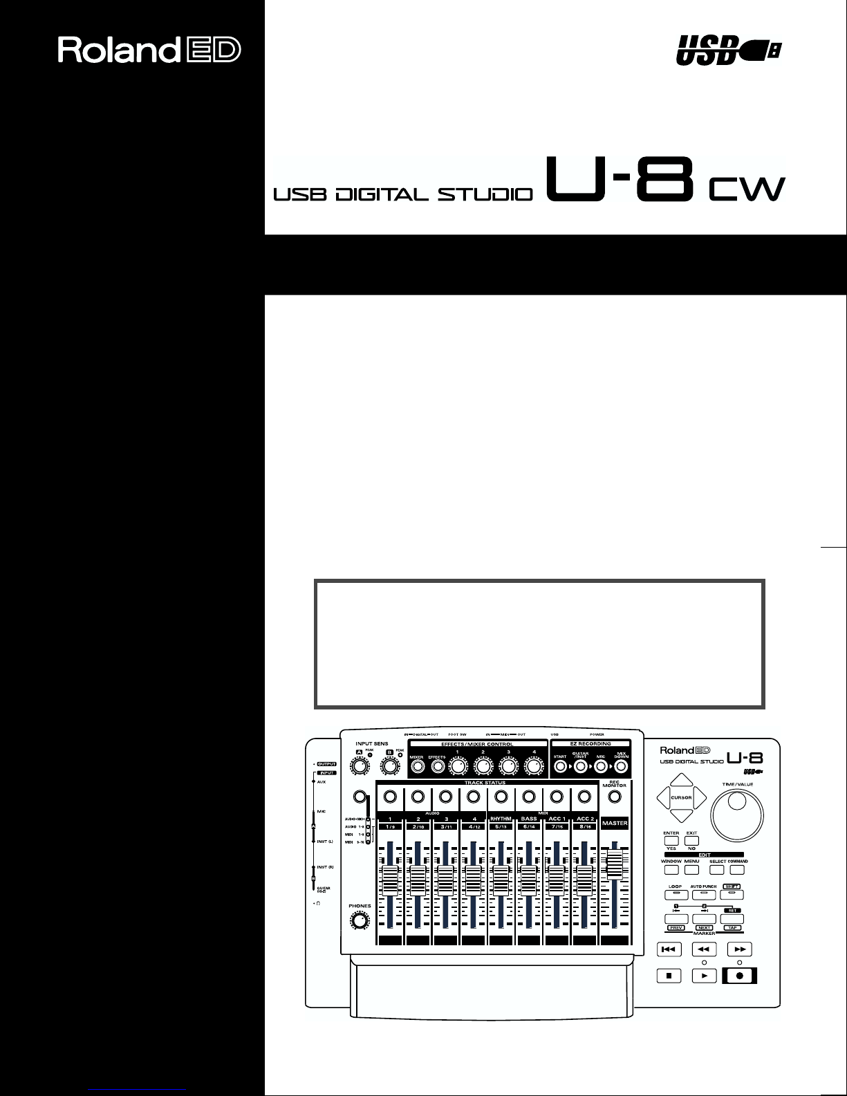
We want to thank you for your purchase of the U-8. The U-8 is a digital
studio that you can connect to your computer to compose songs using a
sequencer program.
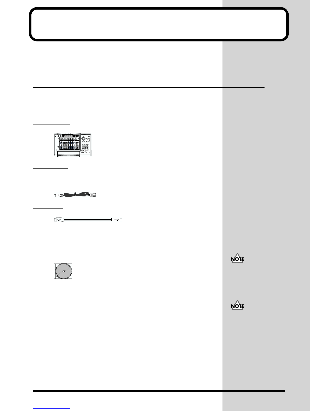
Checking What’s in the Package
The U-8 includes the following items. When you open the package, first
check to make sure that all the included items are present. If something is
missing, contact the dealer where you bought it.
U-8 Main Unit
fig.00-01
OUTPUT
INPUT
AUX
MIC
AUDIO+MIDI
AUDIO
MIDI
)
A(L
MIDI
)
B(R
GUITAR
(
)
Hi-Z
Power Cable
This is used to connect the power supply for the U-8. For more on how to
connect it, take a look at “4. Connecting the Power Supply (p. 18).”
fig.00-02.e
FOOT SW OUTIN MIDI
OUTIN
DIGITAL
EFFECTS/MIXER CONTROL
PEAK
PEAK
A
B
MIXER
EFFECTS
4
4
50dBm
50dBm
AUDIO
1234
1-8
1/9 2/10 3/11 4/12 5/13 6/14 7/15 8/16
1-8
9-16
PHONES
010
TRACK STATUS
RHYTHM BASS ACC 1 ACC 2
USB
POWER
EZ RECORDINGINPUT SENS
4321
GUITAR
MIX
/INST
DOWN
MIC
START
USB DIGITAL STUDIO
U-8
REC
VALUE
MONITOR
CURSOR
MIDI
MASTER
EXITENTER
NO
YES
EDIT
MENU
WINDOW
COMMAND
SELECT
AUTO PUNCH
SHIFTLOOP
2
1
SET
TAPNEXTPREV
MARKER
USB Cable
fig.00-08
This is used to connect the USB connector on the U-8 to the USB connector
on the computer. For more on how to connect it, see “5. Connecting to the
Computer (p. 18).”
CD-ROM
fig.00-03
Before opening the
included CD-ROM, be sure
to read the separate
Roland License
The CD-ROM includes the following software.
Agreement.
U-8 Driver
This software is necessary to enable the computer to recognize the U-8. For
information on how to install it, see “Getting Ready to Use the U-8 with a
Computer (p. 24).”
* Before you install the U-8 driver, be sure to read “Before You Install the U-8
Driver” (p. 24).
Cakewalk Home Studio U-8
Cakewalk Home Studio U-8 is digital recording software you can use with
the U-8.
For information on how to install it, see “Preparing for Use of the Included
Programs (Installing the included software) (p. 20).”
Do not touch or scratch the
lower (data) surface of the
disc. Doing so may make it
impossible to read data
correctly. If the disc
ecomes dirty, clean it with
a commercially available
CD cleaner designed for
that purpose.
6
Page 7

Cakewalk Home Studio U-8 Manual
This describes the details of Cakewalk Home Studio U-8. You can view this
manual using Acrobat Reader, supplied by Adobe Systems Incorporated.
For more information on how to view this manual, see “How to View the
Online Manuals (p. 53).”
U-8 Controller
This program controls the U-8’s mixer and effects. For information on how
to set up the program, see “Preparing for Use of the Included Programs
(Installing the included software) (p. 20).” Also, for more information,
refer to the U-8 Controller Manual described below.
U-8 Tuner
This is a special U-8 feature for tuning electronic guitars. For details, refer to
the U-8 Tuner Manual described below.
Virtual Sound Canvas 3.0
Virtual Sound Canvas 3.0 (VSC 3.0) is a MIDI software synthesizer. When
used with the U-8, you can play and record MIDI data without an external
sound module, using only your computer.
For how to install VSC 3.0, refer to p.35.
Introduction
Demo Songs
These are demo songs for Cakewalk Home Studio U-8.
Style Data (SMF)
Style data comprise typical performance patterns representing a variety of
musical genres that are stored as SMF performance data.
Online Manuals
You can view the online manuals shown below with a Web browser
(Internet browser) such as Microsoft Internet Explorer or Netscape
Navigator.
For more information about each of the online manuals, please see “How to
View the Online Manuals (p. 53).”
Troubleshooting
If there’s a problem, such as no sound, viewing Troubleshooting will give
you some possible solutions.
U-8 Technical Guide
This describes the details of effects, special examples of connections with the
U-8, exchange of MIDI messages with the U-8, the details of the U-8’s onboard digital mixer, and more.
U-8 Controller Manual
This describes how to use the U-8 Controller.
7
Page 8
Introduction
U-8 Tuner Manual
This describes how to use the U-8 Tuner.
Preset Effect Patch List
This is a list of preset data for effects.
Getting Started
fig.00-04.e.eps_20
This is the document you are reading. Keep it by you for reference whenever
you operate the U-8.
Roland License Agreement
fig.00-05.e.eps_10
These are contracts by which Roland allows you, the customer, to use the
software. Be sure to read these before opening the package of the CD-ROM.
Cakewalk Product Registration Card
Please fill out and send in the registration card that comes in this package.
Doing so will make sure you are entitled to technical support and kept
aware of updates and other news regarding Cakewalk products.
What You Can Do with the U-8
Achieving a Personal Digital Recording Studio in Combination
with Your Computer.
You can use the U-8 with a sequencer program to achieve the same range of
songmaking operations as a recording studio, including recording, mixdown, and mastering.
Easy Operation Using the U-8 Unit Together with a Sequencer
You can perform practically all tasks quickly and easily using just the U-8
itself, including song playback, recording, rewinding, fast forward, and
effect settings.
8
Page 9
Professional Effects Processor That Draws on Roland’s
Experience in Musical Equipment
The high-performance DSP multi-effect processor in the U-8 is provided
with carefully selected algorithms for guitar, vocals, and recording.
A special graphical controller enables easily understood control for effect
parameters.
The algorithms include Guitar Multi effects, allowing you to apply a rich
range of guitar effects, Vocal Multi effects for a variety of vocal sounds, and
finally, Mastering effects, which add power to mixed songs.
MIDI Interface
The unit is equipped with a MIDI interface that lets you connect an external
MIDI sound module and play backing.
Simple Connection to Your Computer Via USB Cable
You can make connections even when the power is turned on. No special
settings are required.
Introduction
Optical Digital Input/Output
You can digitally acquire sounds from MDs and CDs for use as backing
data, or record mastered songs to DAT or MD directly in digital form.
About Copyrights
The law prohibits the unauthorized recording, public performance,
broadcast, sale, or distribution etc. of a work (CD recording, video
recording, broadcast, etc.) whose copyright is owned by a third party.
Roland will take no responsibility for any infringement of
copyright that you may commit in using the U-8.
About SCMS
SCMS stands for Serial Copy Management System. This is a
function that protects the rights of copyright holders by prohibiting
recording via a digital connection for more than two generations.
When digital connections are made between digital recorders that
implement this function, SCMS data will be recorded along with
the audio data. Digital audio data which contains this SCMS data
cannot again be recorded via a digital connection.
9
Page 10
Introduction
■ What Is USB?
USB stands for Universal Serial Bus, and is a new interface used to connect
various peripherals to a computer.
USB allows a variety of peripheral devices to be connected via a single USB
cable, and is far faster than the earlier serial port, allowing audio to be
recorded or played while playing MIDI data.
It also allows peripheral devices to be connected or disconnected while the
power is left on, and the computer will automatically recognize such
devices. (For some peripherals, it may be necessary to make settings or
perform other procedures.)
■ GM/General MIDI
fig.GM Logo
General MIDI is a set of recommendations which seeks to provide a way to
go beyond the limitations of proprietary designs, and standardize the MIDI
capabilities of sound generating devices. Sound generating devices and
music files that meet the General MIDI standard bear the General MIDI logo
().
Music files bearing the General MIDI logo can be played back using any
General MIDI sound generating unit to produce essentially the same
musical performance.
■ GM 2/General MIDI 2
fig.GM2 Logo
The upwardly compatible General MIDI 2 ( ) recommendations pick
up where the original General MIDI left off, offering enhanced expressive
capabilities, and even greater compatibility.
Issues that were not covered by the original General MIDI
recommendations, such as how sounds are to be edited, and how effects
should be handled, have now been precisely defined. Moreover, the
available sounds have been expanded.
General MIDI 2 compliant sound generators are capable of reliably playing
back music files that carry either the General MIDI or General MIDI 2 logo.
In some cases, the conventional form of General MIDI, which does not
include the new enhancements, is referred to as “General MIDI 1” as a way
of distinguishing it from General MIDI 2.
10
Page 11
■ GS
Introduction
fig.GS Logo
The GS Format ( ) is Roland’s set of specifications for standardizing the
performance of sound generating devices. In addition to including support
for everything defined by the General MIDI, the highly compatible GS
Format additionally offers an expanded number of sounds, provides for the
editing of sounds, and spells out many details for a wide range of extra
features, including effects such as reverb and chorus.
Designed with the future in mind, the GS Format can readily include new
sounds and support new hardware features when they arrive.
203
* GS ( ) is a registered trademark of Roland Corporation.
add
* Cakewalk is a registered trademark of Twelve Tone Systems, Inc.
add
* Cakewalk Home Studio, Virtual Piano, StudioWare, and the Cakewalk logo are
trademarks of Twelve Tone Systems, Inc.
* Adobe, the Adobe logo and Acrobat® Reader are trademarks of Adobe Systems
Incorporated.
* Microsoft, Windows, and Windows NT are registered trademarks of Microsoft
Corporation.
206c
* Windows® 98 is known officially as: “Microsoft® Windows® 98 operating
system.”
206f
* Windows® 2000 is known officially as: “Microsoft® Windows® 2000 operating
system.”
206e
* Screen shots reprinted with permission from Microsoft Corporation.
213
* Pentium is a registered trademark of Intel Corporation.
214
* MMX is a trademark of Intel Corporation.
220
* All product names mentioned in this document are trademarks or registered
trademarks of their respective owners.
985
* The explanations in this manual include illustrations that depict what should
typically be shown by the display. Note, however, that your unit may incorporate a
newer, enhanced version of the system (e.g., includes newer sounds), so what you
actually see in the display may not always match what appears in the manual.
11
Page 12
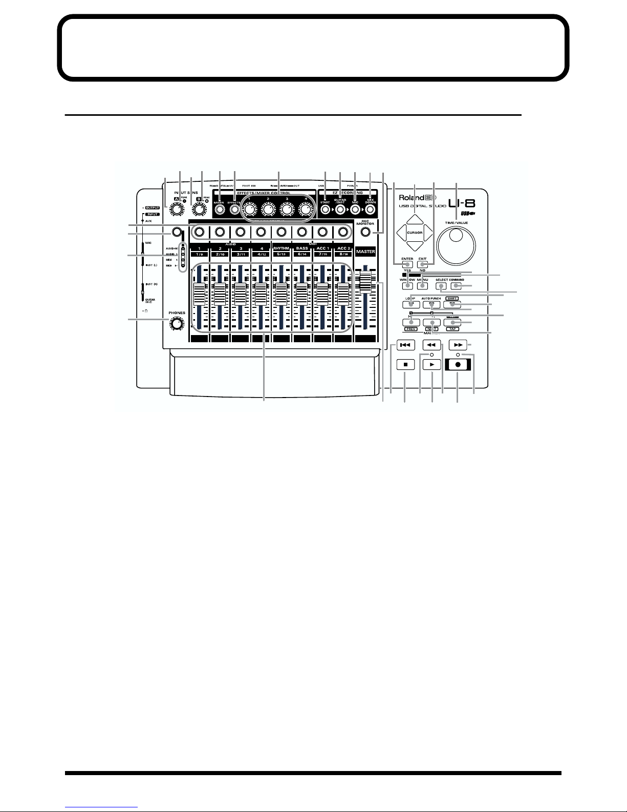
Panel Descriptions
Top Panel
* The functions of the top panel controls may differ depending on the sequencer used in conjunction with your U-8. For more detailed
information, refer to your sequencer’s manual.
fig.03-01
27 28
34
39
38
40
323033
31
29
13
14 15
16
36
2
3
41
2
1
17
20
22
26
10
23
25
18
21
24
19
35
1.TIME/VALUE Dial
Moves the song position (the present time) forward and
backward.
When setting a parameter value, turn it clockwise to raise
the value or counterclockwise to lower it.
2.ENTER Button
When setting a parameter, this “locks in” the present value
as the parameter’s new value.
At other times, it’s used to answer “yes” to questions or to
press the button under the cursor.
3.EXIT Button
When setting a parameter, this cancels the setting.
At other times, it’s used to answer “no” to questions.
4.CURSOR Buttons
Move the cursor and item selections up, down, left, and
right.
5.Record Indicator
Lights up during recording.
6.Playback Indicator
Lights up to show the progress of playback or recording.
12
37
6
98
11
5
7
7.Record Button
This initiates recording.
8.Play Button
Starts playback or recording.
9.Stop Button
Stops playback or recording.
10.Fast-forward Button
Fast-forwards the song.
11.Rewind Button
Rewinds the song.
12.To Start of Song Button
Rewinds to the start of the song.
13.START Button
Starts songmaking. A dialog box appears and guides you
through the procedure.
14.GUITAR/INST (Guitar/Instrumental) Button
Starts recording for a guitar or another instrument. A dialog
box appears and guides you through the procedure.
12
Page 13

Panel Descriptions
15.MIC (Microphone) Button
Starts recording with a microphone. A dialog box appears
and guides you through the procedure.
16.MIX DOWN Button
Starts mix-down. A dialog box appears and guides you
through the procedure.
17.WINDOW Button
Switches the top window displayed with the sequencer
program.
18.MENU Button
Displays the menu for the sequencer program.
19.SELECT Button
This selects the target of an operation according to
circumstances with the sequencer program.
20.COMMAND Button
This calls up editing commands or the like according to
circumstances with the sequencer program.
* In Cakewalk, use this button to undo your last action.
21.LOOP Button
When the button has been pressed and the LED is lit up, this
performs loop playback or recording in a range specified by
Locate points.
22.AUTO PUNCH Button
When the button has been pressed and the LED is lit up, this
performs auto punch in/out or recording in a range
specified by Locate points.
23.SHIFT Button
After pressing this button to light it up, activates the other
button’s alternate function.
29.EFFECTS/MIXER CONTROL 1 to 4 Knobs
When the Effects Edit or Mixer Control screen has been
displayed by pressing the EFFECTS or MIXER button, these
controls change the values of the parameters assigned to
each one.
30.Input A Peak Indicator
Lights up when the signal from A input or Mic input is too
high.
31.Input B Peak Indicator
Lights up when the signal from B input or Guitar input is
too high.
32.Input A Sensitivity Volume Knob
This adjusts the signal level for A input or Mic input.
33.Input B Sensitivity Volume Knob
This adjusts the signal level for B input or Guitar input.
How to Adjust the Input A/B Level
For instructions on adjusting the Input A/B levels, refer
to “How to Match the Input Levels ”(p. 56).
34.Track Status Buttons
Change the status of the tracks (play, mute, or the like).
35.Track Volume Faders
Set the volume for tracks.
36.REC (Record) MONITOR Button
Switches the Record monitor (the sound output during
recording). When lighted, only the sound being recorded is
output. When dark, all sound is output.
37.Master Volume Fader
Adjusts the overall volume level.
24.MARKER Button (PREV)
This moves the song position to the previous marker.
What Is a
This is a feature for remembering a song position. For
details, see the manual of the sequencer program.
MARKER?
25.MARKER Button (NEXT)
This moves the song position to the next marker.
26.Locator Set Button (TAP)
Pressing the TAP button inserts a marker to the present
song position.
27.MIXER Button
Displays the Mixer Control screen.
28.EFFECTS Button
Displays the Effects Edit screen.
38.Track Group Indicators
These show the present assignments of the Track Volume
faders and the Track Status buttons.
39.Track Group Select Button
Used to select the Track Groups assigned to the Track
Volume faders and the Track Status buttons.
40.Headphones Volume Knob
Adjusts the volume level of the output from the headphones
jack. Turn it counterclockwise to lower the volume, or
clockwise to raise it.
13
Page 14
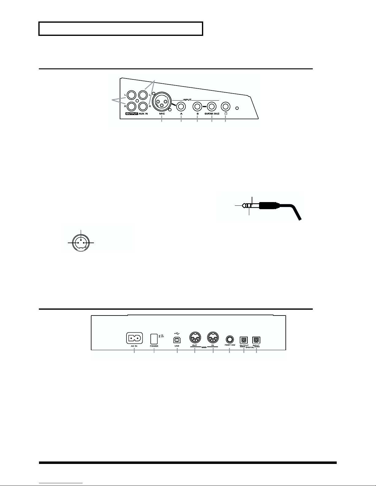
Panel Descriptions
Side Panel
fig.03-02
1
1.Line Output Jacks
These are for connecting equipment such as an external
stereo set or speaker with built-in amplifier.
2.AUX Input Jacks
These are for connecting external equipment, such as a
MIDI sound module, or CD and MD players.
3.Mic Input Jack
This is for connecting an XLR type (unbalanced input)
microphone.
* The pin assignments for the XLR type connectors are as shown below.
Before making any connections, make sure that these pin assignments are
compatible with that of all your other devices.
fig.03-04
3
1:GND
12
* Because pin 3 is connected to ground (GND), when connecting a
balanced-output device, make sure that unbalanced connection is possible.
* When using the A Input jack at the same time, the signal from the A Input
jack takes priority, and the signal from the Mic Input jack is not input.
2:HOT
3:GND
2
34567
Rear Panel
fig.03-03
4.A Input Jack
This is for connecting standard output from a 1/4 inch
phone mike, a TRS-phone (unbalanced input) mike,
synthesizer, or the like.
* The pin assignment of a TRS-phone mike is as shown below. Before
making any connections, make sure that this pin assignment is compatible
with all your other devices.
* Because RING is connected to ground (GND), when connecting a
balanced-output device, make sure that unbalanced connection is possible.
fig.03-05
HOT (TIP)
GND (SLEEVE)
COLD (RING)
5.B Input Jack
Connect the guitar after routing it through your multieffects processor or similar equipment. It’s also for
connection to synthesizer output.
6.Guitar Input Jack
This is for direct high-impedance connection to a guitar.
* When using the B Input jack at the same time, the signal from the B Input
jack takes priority, and the signal from the Guitar Input jack is not input.
7.Headphones Jack
This is for connecting headphones. Sound is output from the
Line Output jacks even when headphones are connected.
1.AC Inlet
This is for connecting the power cord.
2.Power Switch
This switches the power on and off.
3.USB Connector
By connecting this to a computer using a USB cable, you can
exchange audio signals, MIDI signals, and U-8 control signals.
4.MIDI OUT Connector
This is for connecting to the MIDI input on another MIDI
instrument to send MIDI messages.
5.MIDI IN Connector
This is for connecting to the MIDI output on another MIDI
instrument to receive MIDI messages.
14
213 67845
6.Foot Switch Jack
This is for connecting a foot switch. When the U-8 Mixer is
activated, you can use this switch to inclement an effect
patch in the Effect Patch Manager. Otherwise, this switch
works as the same as the Play and Stop Button.
7.Digital Output Connector
This is for making the connection for digital output to
digital audio equipment such as a DAT or MD device.
8.Digital Input Connector
This is for making the connection for digital input from
equipment such as a CD, MD, or DAT device.
Page 15
Getting Ready to Use the U-8
Connecting the Unit
To use the U-8, you need to connect a computer, and headphones or an
amplifier. Refer to the explanation below, and make the connections that
best suit your setup.
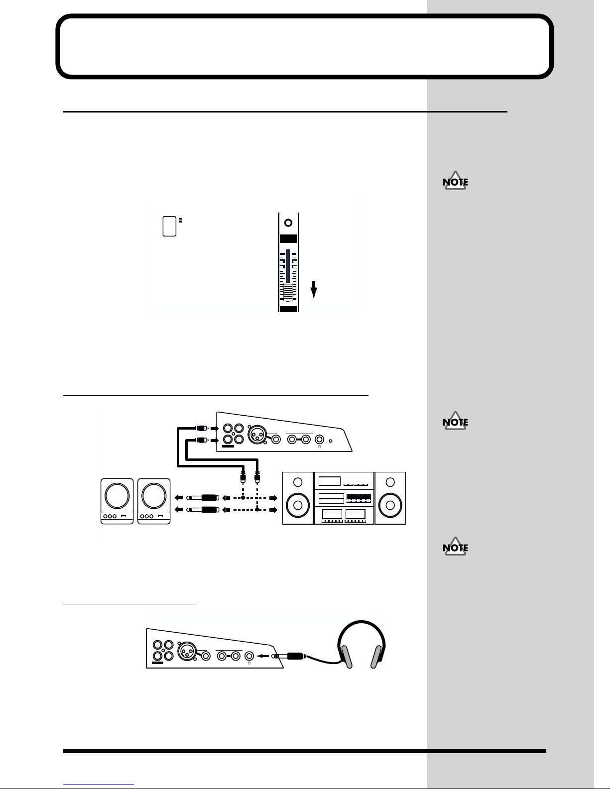
Before making connections, make sure that (1) the power switch is turned
off and (2) the Master Volume fader is lowered all the way.
fig.04-09.e
1. 2.
ON
OFF
POWER
REC
MONITOR
MASTER
Switch off the power button. Lower all the way.
1. Making Connections for Hearing Sound
To hear sound from the U-8, use one of the methods below to make the
connections.
You will need to acquire
and have on hand
whatever equipment or
cables (other than what
came with the U-8) that
you need. When doing this,
take care to ensure that the
configuration of the cable
connectors is compatible.
Connecting a Speaker with a Built-in Amp or a Stereo Set
fig.04-03.e
OUTPUT L
L
Powered Speaker
INPUT
OUTPUT R
L
R
Left
Right
OUTPUT
R
AUX IN
LINE IN
INPUT
)
BAMIC
GUITAR (Hi-Z
U-8
Stereo Set
Use the Master Volume fader on the top panel of the U-8 or the volume knob
on the speaker with built-in amp or stereo set to adjust the volume level.
(921)
Connecting Headphones
fig.04-02
L
L
R
R
AUX IN
OUTPUT
Use the Master Volume fader or the Headphones Volume knob on the top
panel to adjust the volume level for headphones.
INPUT
)
BAMIC
GUITAR (Hi-Z
To prevent malfunction
and/or damage to speakers
or other devices, always
turn down the volume, and
turn off the power on all
devices before making any
connections.
When making a digital
connection between the U-8
and a stereo set, connect
the Digital Output
connector on the U-8 to the
Digital Input connector on
the stereo set. For more
information, refer to
“Making a Digital
Connection” in “U-8 and
External Equipment” in
the U-8 Technical Guide.
15
Page 16
Getting Ready to Use the U-8
j
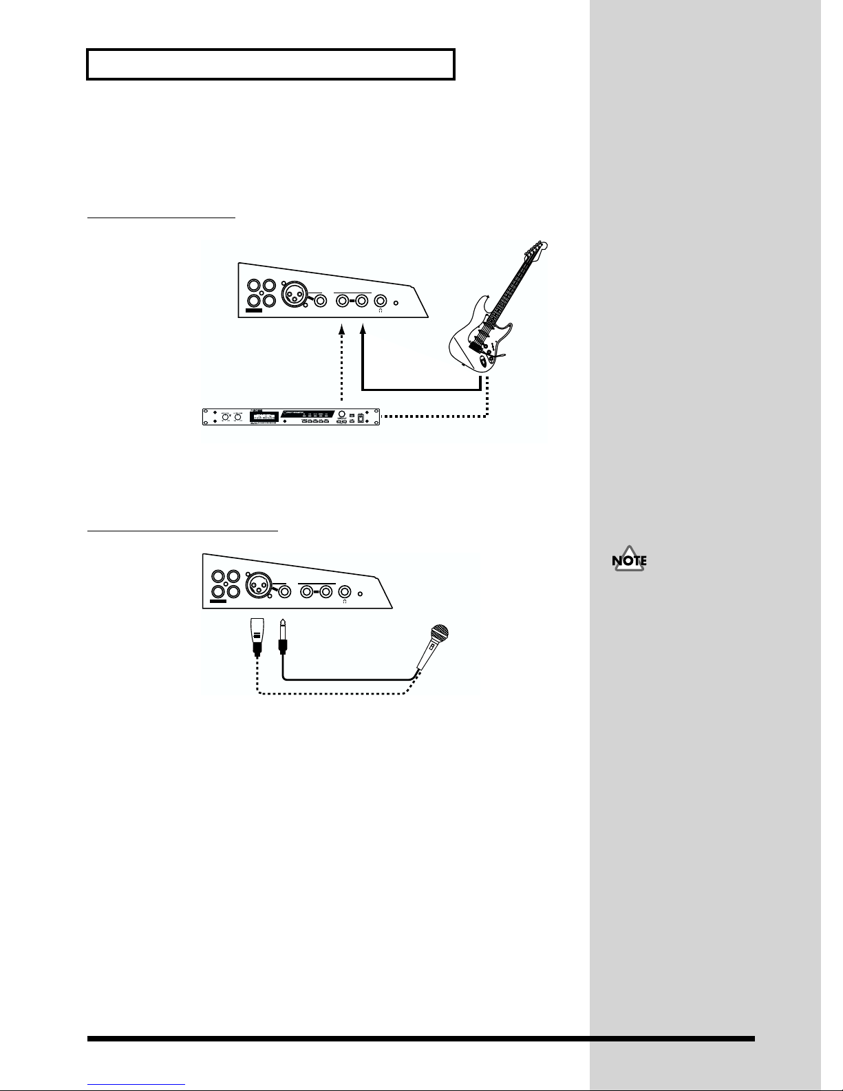
2. Making Connections for Recording
To record sound through the U-8, use one of the methods below to make the
connections.
Connecting a Guitar
fig.04-04.e
L
L
R
R
AUX IN
OUTPUT
Multiple Effects Processor
In general, when connecting a guitar directly, connect it to the Guitar Input
jack, and when connecting a guitar through an multiple effects processor,
or the like, connect it to the B Input Jack.
INPUT
)
BAMIC
GUITAR (Hi-Z
GUIT AR (Hi-Z)B INPUT
Connecting a Microphone
fig.04-05.e
L
L
R
R
AUX IN
OUTPUT
MIC
XLR type
If the connector on the cable connected to the mike is an XLR one, connect it
to the Mic Input jack. If it is a 1/4” phone plug, connect it to the A Input jack.
(983)
* Howling could be produced depending on the location of microphones relative to
speakers. This can be remedied by:
1) Changing the orientation of the microphone(s).
2) Relocating microphone(s) at a greater distance from speakers.
3) Lowering volume levels.
INPUT
)
BAMIC
GUITAR (Hi-Z
A INPUT
1/4" phone type
Microphone
Make sure that the
microphone you’re
connecting to the Mic Input
ack or the A Input jack
complies with the pin
assignments described for
the Mic Input jack or the A
Input jack under “Side
Panel (p. 14).”
16
Page 17
Getting Ready to Use the U-8
Connecting a Device Such As a
fig.04-06
CD Player, MD Player, or DAT Player
U-8
L
OUTPUT
AUX IN
AUX IN
INPUT
RLR
)
BAMIC
GUITAR (Hi-Z
Connect the analog output from the CD player, MD player, DAT player, or
the like to the AUX Input jack on the U-8.
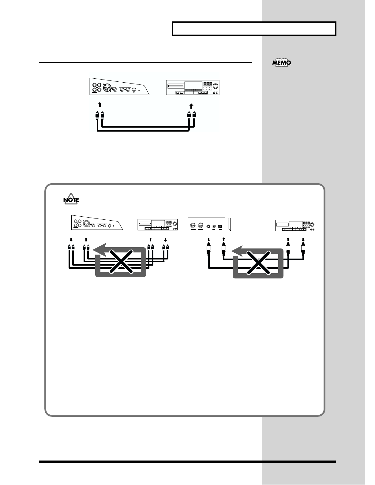
Be careful of loop connections
fig.04-06a.e
L
OUTPUT
U-8
INPUT
RLR
AUX IN
AUX INOUTPUT
)
BAMIC
GUITAR (Hi-Z
MD/DAT/CD-R
LINE OUT
LINE IN
CD/MD/DAT
LINE OUT
INOUT
MIDI
U-8
FOOT SW
OUTPUT INPUT
DIGITAL
When making a digital
connection between the U-8
and the CD player, MD
player, DAT player, or the
like, connect the digital
output from the CD, MD,
or DAT player to the
Digital Input connector on
the U-8. For more
information, refer to
“Making a Digital
Connection” in “U-8 and
External Equipment” in
the U-8 Technical Guide.
MD/DAT/CD-R
INPUTOUTPUT
OUTPUTINPUT
Example of an Analog Loop Connection Example of a Digital Loop Connection
When the U-8 is connected as shown in the above diagram to a device that passes the
input sound through to its output (an MD/DAT/CD-R that is recording), the U-8
and that device will form a loop that can cause oscillation, producing an
unexpectedly loud sound.
This type of connection can cause malfunction and damage to speakers and other
equipment; take care to avoid these conditions.
In addition to the above figure, take a moment now to check your connections for the
following conditions.
•Could there be a looped connection between the analog and digital realms?
•Has any looped connection resulted from insertion of a mixer or other piece of
equipment between the devices?
17
Page 18
Getting Ready to Use the U-8
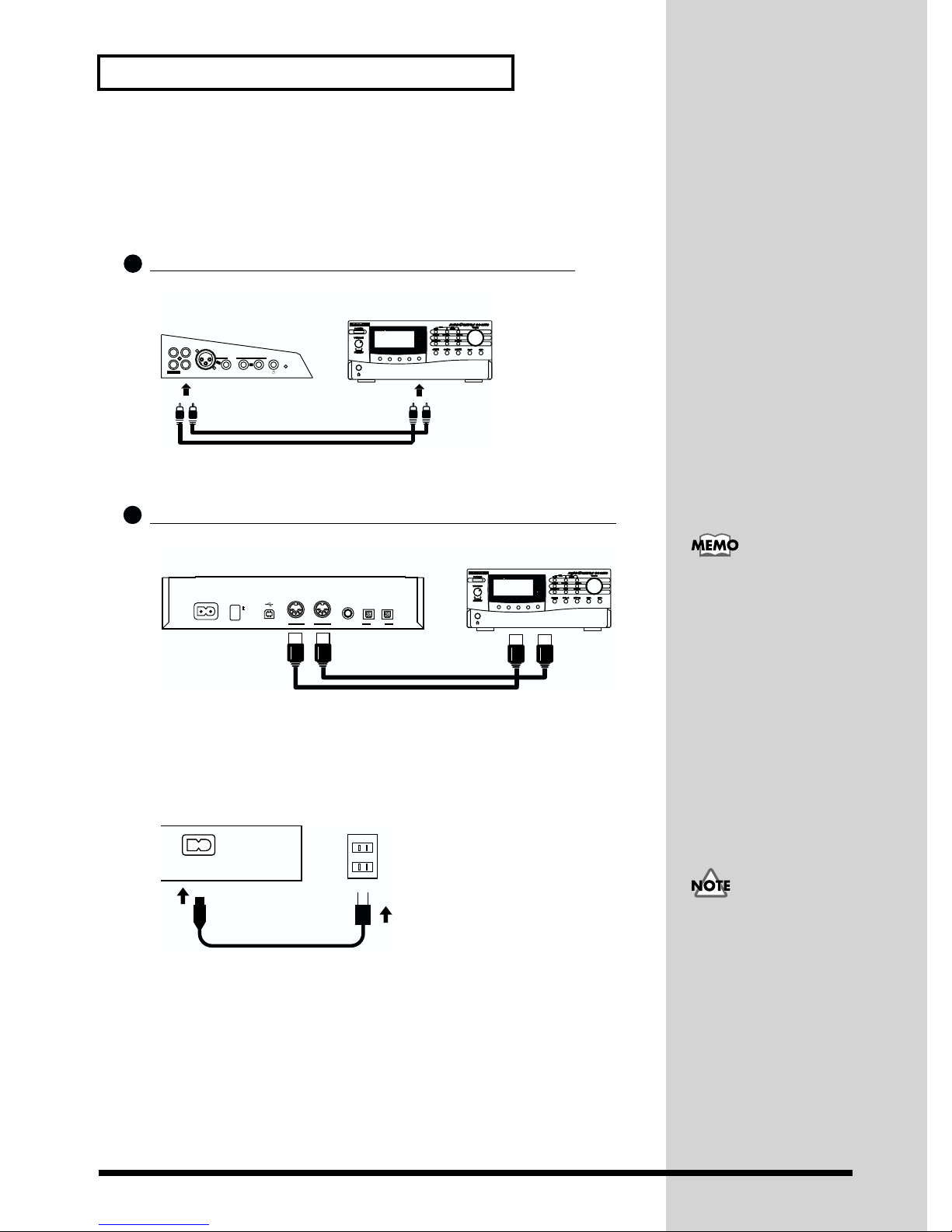
3. Making Connections for Using an External MIDI
Sound Module
This connection is made when playing MIDI data for backing using an
external sound module, such as the SC-8850, SC-8820, or SC-88Pro.
1
Connecting to the Output on a MIDI Sound Module
fig.04-07
U-8
MIDI sound module
L
AUX IN
OUTPUT
RLR
AUX IN
INPUT
)
BAMIC
GUITAR (Hi-Z
Connect the analog output on the external MIDI sound module to the AUX
Input jack on the U-8.
2
Connecting a MIDI Sound Module and the U-8 with MIDI
fig.04-08
U-8
ON
OFF
USBPOWERAC IN
MIDI OUT MIDI IN
INOUT
FOOT SW
OUTPUT INPUT
MIDI
DIGITAL
Make the connection with a MIDI cable to enable the external MIDI sound
module and the U-8 to exchange messages.
4. Connecting the Power Supply
Connect the power cable to the AC inlet and a power outlet.
fig.04-10
LINE OUT
MIDI sound module
MIDI IN
MIDI OUT
When inputting MIDI
messages from another
MIDI instrument or
controller, refer to the
“Connecting a MIDI
Instrument or Controller”
in “U-8 and External
Equipment” in the U-8
Technical Guide.
AC IN
U-8
(941)
5. Connecting to the Computer
Before connecting the U-8 to the computer, be sure to install the included
software. If you do not install them first, there is a case that the U-8 driver
cannot be installed correctly. For more information, refer to “Preparing for
Use of the Included Programs” (p. 20).
18
After properly making the
connections explained up
to this point in the
instructions, be sure to
follow the procedure
described in “Turning On
the Power” to turn on the
power to the U-8. Errors in
this process may result in
malfunction or in damage
to the connected speakers.
Page 19
■ What Else You Need to Use the U-8
External Amp, Speakers, Headphones, Microphone, and
Cables to Connect Them Are Not Included
The external amp, speakers, or headphones and the cables for connecting
them that you will need in order to hear the sound from the U-8 are not
included. A microphone for connection to the U-8 to input audio must also
be purchased separately. You will need to provide these items yourself.
MIDI Sound Module Is Not Included
A MIDI sound module for playing backing performances using a sequencer
is not included.
U-8 comes with software MIDI synthesizer, Virtual Sound Canvas 3.0. MIDI
performances are also possible with this software, but in cases of real-time
MIDI input and the like, we recommend connecting a hardware sound
module such as the SC-8850, SC-8820, or the SC-88Pro.
CD, DAT, or MD Devices and the Cables for Connecting Them
Are Not Included
You can make digital connections to a CD player, DAT recorder, MD
recorder, and the like, but these devices and cables for making the analog or
digital connections to them are not included. You will need to provide this
yourself.
Getting Ready to Use the U-8
For information on how to
install VSC3.0, see
“Installing Virtual Sound
Canvas 3.0 (VSC 3.0) (p.
34).”
Web Browser (Internet Browser) Is Not Included
In order to read the Online Manuals on the included CD-ROM, an Web
browser (Internet browser) such as Netscape Navigator or Microsoft
Internet Explorer must be already installed and set up on your computer.
You will need to provide this yourself.
Turning On the Power
■ When Turning On the Power for the First Time
Before you turn on the power to the U-8 for the first time, it is necessary to
install the included software. If you do not install them first, the U-8 driver
will not be installed correctly. For more information, refer to “Preparing for
Use of the Included Programs” (p. 20).
When you turn on the power to the U-8 for the first time after installing the
software and connecting the U-8 and the computer, a dialog box appears as
shown below, and preparations for using the U-8 start. Refer to “Getting
Ready to Use the U-8 with a Computer”.
fig.05-01.e.eps_50
19
Page 20
Getting Ready to Use the U-8
■ When Turning Off the Power
Before turning off the U-8 unit, make sure that all the programs on the
computer that are using the U-8 and that are using audio or MIDI have
finished.
Preparing for Use of the Included Programs
(Installing the included software)
■ Installing U-8 Controller, U-8 Tuner, Cakewalk Home
Studio U-8
Follow the steps below to install U-8 Controller, U-8 Tuner, Cakewalk Home
Studio U-8, and the online manuals on your computer.
1
2
Insert the supplied CD-ROM into your CD-ROM drive.
* Exit all other Windows applications before you install the software.
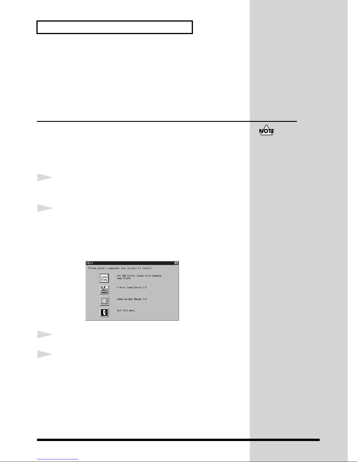
The following dialog comes up automatically.
Click the U-8 CW button.
* If the MENU dialog does not come up automatically, you can also install the
programs by choosing Start - Run and running the application named Setup.exe
from the CD-ROM.
fig.05-07a.e.eps_35
Do NOT turn on the U-8
now. You can turn it on
when you install the U-8
driver.
3
4
20
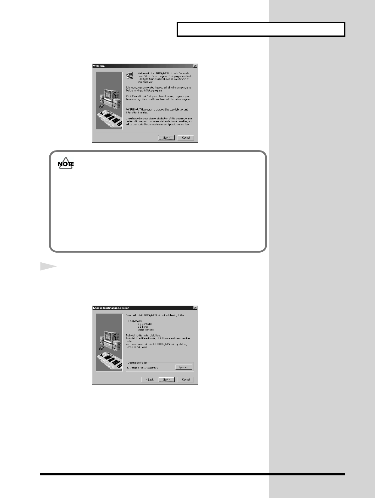
Warning dialog will appear. Read it carefully, and click OK.
The installer will start up. Click Next.
Page 21
Getting Ready to Use the U-8
fig.05-08a.e.eps_35
If the “Welcome” Dialog Box Is Not Displayed
In certain computing environments, you may find that the “Welcome”
dialog box does not appear in the display.
In Step 5, a dialog box with a message telling you to restart your computer
may appear instead of the Welcome dialog box.
In this case, select
After restarting your computer, perform the entire installation procedure over
again from Step 1.
Yes, I want to restart my computer now.
and click OK.
5
The Choose Destination Location dialog box will be displayed. To install
to the specified destination, click Next. If you want to install to a different
folder, click Browse... and select another folder.
fig.05-08b.e.eps_50
Then, click Next.
21
Page 22
Getting Ready to Use the U-8
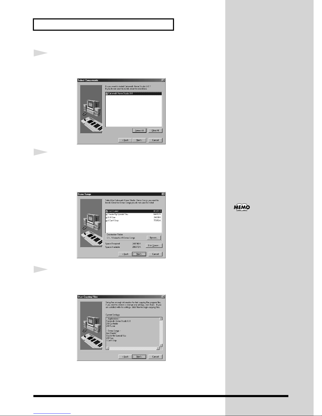
6
7
In the Select Components dialog box, confirm that the required software
has been checked, then click Next.
fig.05-08c.e.eps_50
If you select Cakewalk Home Studio U-8 to be installed, a dialog appears
which asks you whether and to where you want to install the demo songs.
Check the song names that you want to install and specify the destination.
Then, click Next. You can also copy them later.
fig.05-08g.e.eps_50
8
To install the demo song
after Cakewalk Home
Studio U-8 is installed, just
copy the desired song files
on the supplied CD-ROM
to the hard disk.
The software to be installed is shown in the Start Copying Files dialog
box; after confirming what is indicated is correct, click Next.
fig.05-08i.e.eps_50
Then it starts copying files. After this, install each component by following
the instructions on your screen.
22
Page 23
Getting Ready to Use the U-8
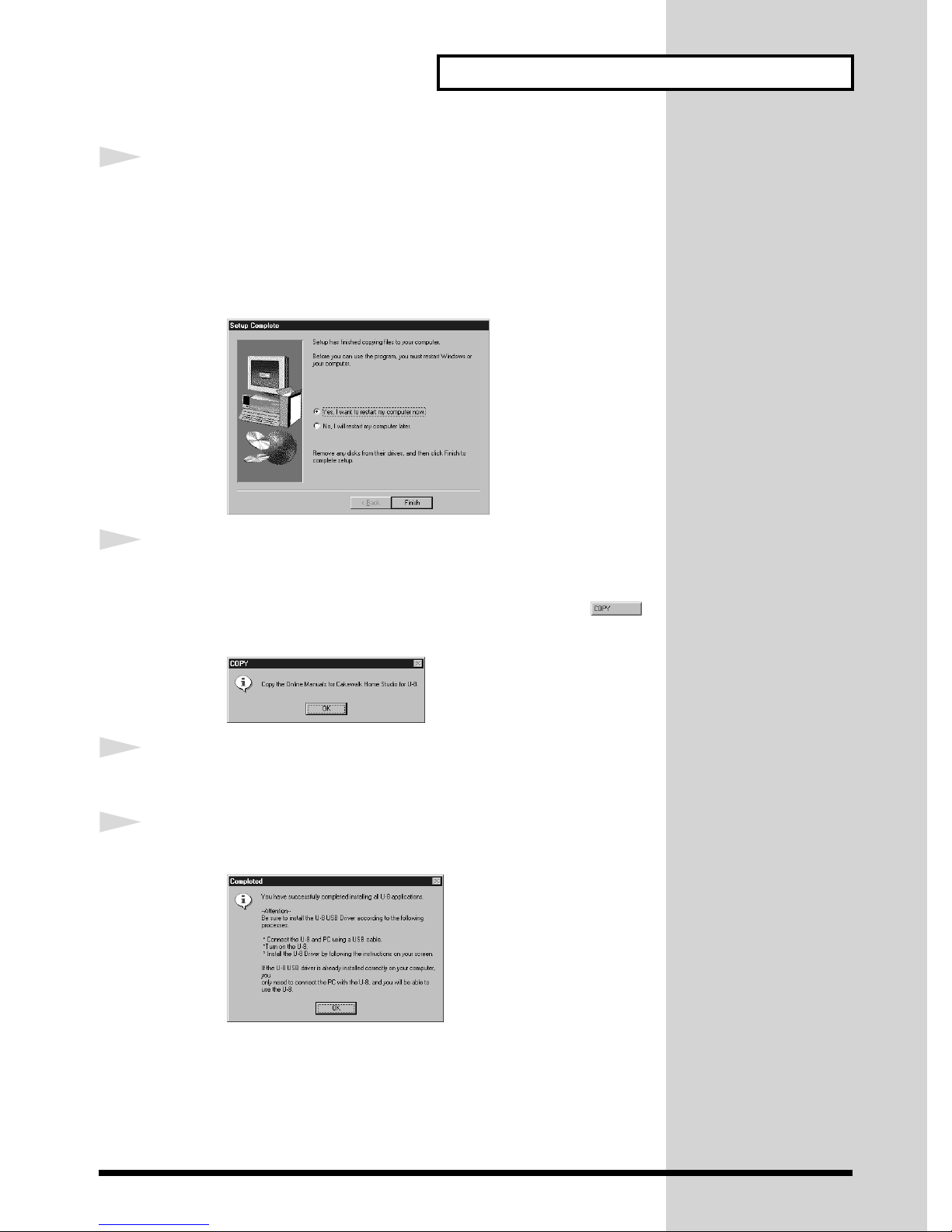
9
10
After installing Cakewalk components, you will be asked whether you
want to restart your computer. To make the settings effective, be sure to
choose Yes, I want to restart my computer now in the Setup Complete
dialog box, then click Finish. Windows will restart.
Since the setup will continue after Windows has restarted, DO NOT take the
CD out of the CD-ROM drive.
fig.05-08e.e.eps_50
After restarting Windows, COPY dialog will appear. Click OK, then some
more files will be copied.
* There is a case that the dialog is layered behind the other windows. Press
on the Windows taskbar to show the dialog to the top.
fig.05-08h.e.eps_50
11
12
Depending on your computer settings, you will see DMA dialog here. Read
the dialog carefully, and press OK.
Click OK in the Completed dialog.
fig.05-08d.e.eps_50
This completes the installation.
To use Cakewalk software with the U-8, you need to connect the U-8 to the
computer and install the driver. For more information, refer to “Getting
Ready to Use the U-8 with a Computer (p. 24).”
23
Page 24

Getting Ready to Use the U-8
Getting Ready to Use the U-8 with a Computer
Before you read this chapter, you need to install the included software first.
If the software is not installed yet, refer to Preparing for Use of the
Included Programs (p. 20) to install them.
■ Before You Install the U-8 Driver
You cannot use the U-8 with Windows95, Windows NT, nor
Windows 2000.
If an older version of the U-8 Driver is already installed in your
computer, you must delete it as explained in “Deleting the U-8
Driver (p. 57).”
Exit all other Windows applications before you install the U-8
driver.
If you will be connecting your computer to both the U-8 and another
Roland USB-compatible device such as the UM-4 (Super MPU64)
and using them at the same time, you must disconnect the other
device (UM-4 etc.) from the USB connector before installing the U-8
Driver. If the UM-4 etc. remains connected at the time that the U-8
Driver is installed, the U-8 Driver may not be installed correctly.
24
Page 25

Getting Ready to Use the U-8
If using a computer upgraded from Windows95 to Windows98,
be sure to note the following points.
In the Control Panel of your computer, the Preferred device list for
Playback or Recording in Multimedia-Audio may contain a voice modem
device such as Voice Modem Wave #00 Line or Voice Modem Wave #00
Handset. (The name may differ depending on your computer.)
If these are already present when you install the U-8 Driver and you re-start
Windows, it may be impossible to start (re-start). The operation of your
computer may also become unstable.
If using a computer upgraded from Windows95 to Windows98, use the
following procedure to first set the Voice Modem Wave #00 Line and/or
Voice Modem Wave #00 Handset devices to the Disabled state.
1. Click the Windows Start button, point to Settings and select Control
Panel. Next, in the Control Panel, double-click System.
The System Properties dialog box will appear.
2. Click the Device Manager tab.
3. Double-click Sound, video and game controllers.
A list of devices will appear. If the list of devices does not contain Wave
Device for Voice Modem, click OK to end the procedure.
fig.02-02.e.eps
4. Double-click Wave Device for Voice Modem.
The Wave Device for Voice Modem Properties dialog box will appear.
fig.02-03.e.eps
The name “Wave Device
for Voice Modem” may
differ depending on your
computer system. If so,
select a device named
Voice Modem.
5. Click the General tab and in the Device usage area, click the check box
for Disable in this hardware profile, and then click OK.
25
Page 26

Getting Ready to Use the U-8
b
■ Installing the U-8 Driver
1
Connect the U-8 to the computer.
fig.04-11
USB connector
( )
PC
If the U-8 driver is already
installed in the computer
that you are using, delete
the previously installed U-8
driver before performing
ON
OFF
USBPOWERAC IN
USB
INOUT
FOOT SW
OUTPUT INPUT
MIDI
DIGITAL
U-8
the installation. For details
on deleting the U-8 driver,
refer to “Deleting the U-8
Driver (p. 57).”.
2
With the CD-ROM inserted into your CD-ROM drive, turn on your
computer and start up Windows, and then turn on the U-8.
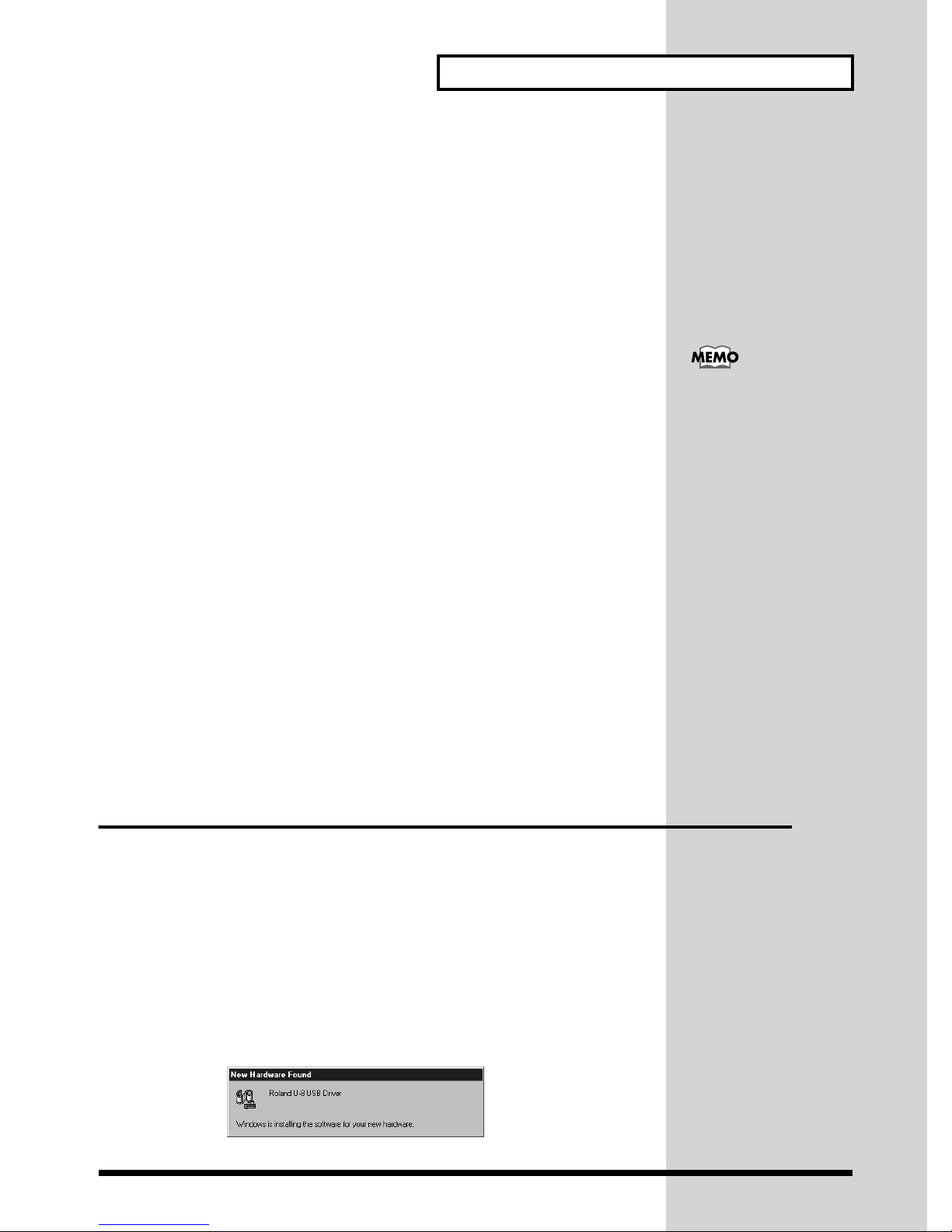
The first time you turn on the U-8 connected to the computer, Windows will
automatically starts searching for the U-8 software. The following dialog
will appear.
fig.05-01.e.eps_50
(942)
(943)
* If the display indicates Unknown Device or USB Composite Device, the
installation procedure cannot be continued, so click Cancel to terminate the
installation procedure.
Afterwards, while referring to "If Installation Doesn’t Proceed As It Should,
Check the Following Points" (p. 27), proceed to check the status of your
computer.
3
Insert Disk dialog will appear. Insert the included CD-ROM into your CDROM drive, and click OK.
fig.05-03a.e.eps_50
Always make sure to have
the volume level turned
down before switching on
power. Even with the
volume all the way down,
you may still hear some
sound when the power is
switched on, but this is
normal, and does not
indicate a malfunction.
This unit is equipped with
a protection circuit. A brief
interval (a few seconds)
after power up is required
efore the unit will operate
normally.
4
New Hardware Found dialog will appear. Type your CD-ROM drive (E:\,
for example) in the Copy files from, and click OK.
26
Page 27

fig.05-03.e.eps_50
Alternatively, you can click Browse, select the root directory of your CDROM drive, and click OK.
This completes the installation of the driver.
If Installation Doesn’t Proceed As It Should, Check the
Following Points
Is the included CD-ROM in the computer’s CD-ROM drive?
Make sure the CD-ROM is in the CD-ROM drive.
Is there enough free hard-disk space?
• Free up more hard-disk space.
Delete unneeded files (move them to the Recycle Bin), then rightclick the Recycle Bin and choose Empty Recycle Bin.
• Add another hard disk.
For details on installing an additional hard disk, refer to the
owner’s manuals for your computer and for Windows.
Was another program running during installation?
Quit all other programs, then repeat the installation.
Getting Ready to Use the U-8
In this explanation we are
assuming that your CDROM drive is drive E:, but
the drive letter may differ
on your computer. If the
drive letter is different on
your computer, input the
appropriate letter. To check
the drive letter of your CDROM drive, double-click
the My Computer icon.
For details on deleting the U-8 driver, refer to p. 57.
Furthermore, refer to "Deleting Unneeded Drivers Installed
with the U-8 Connection" (p. 58) before reinstalling the driver.
In addition to this, “Troubleshooting” on the included CD-ROM has
pointers to remedies for trouble during setup or installation.
1. Place the included CD-ROM in the CD-ROM drive, then use Windows
Explorer to go into the Manual folder and open the TechnicalGuide
folder.
2. Start Internet Explorer or Netscape Navigator.
* You need to provide for an Web browser separately.
3. From Windows Explorer, drag troubleshoot.htm to the Web browser
you started in step 2.
4. Scroll down the window, then view “Points Involving the USB
Connection and Installation of the Driver.”
27
Page 28

Getting Ready to Use the U-8
Starting up Cakewalk Home Studio U-8
To start Cakewalk Home Studio U-8, click on the Home Studio icon on your
desktop, or click on the Windows Start button, and choose Cakewalk -
Cakewalk Home Studio 9 - Cakewalk Home Studio 9 from Programs
menu.
■ Running the program for the first time
For the first time you run Cakewalk Home Studio U-8, Cakewalk Migration
Wizard appears. Generally, it is recommend NOT to migrate the old
Cakewalk settings to the new one.
If you migrate the settings, you can use it with the newly installed
Cakewalk. However, this migration process also deletes some of the U-8
own files. Although these can be restored, migrate the old settings only if it
is necessary.
1
2
Click Cancel to skip the wizard.
fig.0-5.eps_50
If you click OK here to migrate the settings, you need to run another
program to use the U-8. For more information, refer to “Migrating Your Old
Cakewalk Settings to the New One (p. 29).”
Wave Profiler dialog appears. To test your hardware, click Yes.
fig.0-6.eps_50
3
Cakewalk starts.
28
Page 29

Getting Ready to Use the U-8
Migrating Your Old Cakewalk Settings to the New One
If you choose to migrate the old Cakewalk settings to the new one when you
run Cakewalk for the first time, you need to run the setup file below to use
Cakewalk with the U-8.
1. Quit Cakewalk.
2. Insert the supplied CD-ROM to the CD-ROM drive.
3. Double-click the setup.exe on E:\SetCW.
4. If VSC is installed on your computer, you will be asked whether you
want to use it with the U-8. Choose Yes or No.
Once you run this setup program, it also sets the port settings for Cakewalk.
Therefore, it is not necessary to make the settings that is explained after this.
In this explanation we are
assuming that your CDROM drive is drive E:, but
the drive letter may differ
on your computer. If the
drive letter is different on
your computer, input the
appropriate letter. To check
the drive letter of your CDROM drive, double-click
the My Computer icon.
■ Making settings for Cakewalk Home Studio U-8
After installing Cakewalk Home Studio U-8, you need to make the
following settings to use the program.
There are two ways to make the settings. One is to run the auto settings
program and the other is to set it manually.
Auto settings
Running the following program makes the settings for Cakewalk Home
Studio automatically.
And if you migrate the old Cakewalk settings to the new one when you start
Cakewalk for the first time, you have to take run program.
1
2
3
Start Cakewalk and then quit it.
* This process is necessary for Cakewalk to recognize the devices it can use.
Insert the supplied CD-ROM into your CD-ROM drive.
Run the setup.exe on E:\SetCW, and follow the instructions on your
screen.
* If VSC is installed on your computer, you will be asked whether you want to use it
with the U-8. Choose Yes or No.
For information on how to
install VSC 3.0, see
“Installing Virtual Sound
Canvas 3.0” (p. 34).
29
Page 30

Getting Ready to Use the U-8
Manual settings
Settings for the MIDI device
If you migrated the old Cakewalk settings to the new one, you cannot use
Cakewalk Home Studio with the U-8 even if you follow the procedure
below. In that case, be sure to read Migrating your old Cakewalk setting
to the new one (p. 29) and run the auto settings program.
1
2
3
Choose Options-MIDI Devices to open the MIDI Ports dialog box.
In the Input Ports column, select U-8 MIDI IN and U-8 CONTROL IN.
In the Output Ports column, select U-8 MIDI OUT (or Roland VSC 3.0 if
you are using VSC 3.0) and press the Move Selected Devices to Top
button so that it appears at the top of the list. Then, select U-8 CONTROL
OUT.
Using the U-8 for the MIDI output port
fig.32-1.e.eps_45
Using VSC for the MIDI output port
fig.32-4.e.eps_45
4
1
2
3
30
Click OK to finish the settings.
Settings for the AUDIO device
Choose Options-Audio to open the DirectShow Audio dialog box.
Click the General tab.
In the Playback Timing Master column, select U-8 WAVE OUT 1
[MASTER] (or Roland VSC 3.0 if you are using VSC 3.0) and in the
Record Timing Master column, select U-8 WAVE IN.
Page 31

fig.32-2.e.eps_45
Getting Ready to Use the U-8
4
5
Click the Drivers tab.
Select U-8 WAVE IN in the Input Drivers column, and U-8 WAVE OUT 1
[MASTER] and U-8 WAVE OUT 2 [EFFECTS] in the Output Drivers
column. Or, if you are using the U-8 with VSC 3.0, select Roland VSC 3.0,
and do not select other drivers.
Using the U-8 for the Audio Output driver
fig.32-3.e.eps_45
Using VSC for the Audio Output driver
fig.32-6.e.eps_45
6
Click OK to finish the settings.
31
Page 32

Getting Ready to Use the U-8
2
b
Making Audio and MIDI Settings in Windows
This section explains the settings according to your computing setup for
how the sounds that Windows outputs (warning beeps and audio output
from Media Player or the like) are handled.
fig.12-10.e
1
Audio output from Cakewalk Home Studio U-8
2
Audio output such as warning sounds in Windows
PC
2
1
U-8
FOOT SW OUTIN MIDI
PEAK
PEAK
A
B
OUTPUT
INPUT
4
4
50dBm
50dBm
AUX
MIC
AUDIO+MIDI
1234
1-8
AUDIO
1/9 2/10 3/11 4/12 5/13 6/14 7/15 8/16
1-8
MIDI
)
A(L
9-16
MIDI
)
B(R
GUITAR
(
)
Hi-Z
PHONES
010
USB
POWER
OUTIN
DIGITAL
EFFECTS/MIXER CONTROL
EZ RECORDINGINPUT SENS
4321
GUITAR
MIX
MIXER
/INST
DOWN
MIC
EFFECTS
START
USB DIGITAL STUDIO
U-8
REC
TRACK STATUS
AUDIO
RHYTHM BASS ACC 1 ACC 2
VALUE
MONITOR
CURSOR
MIDI
MASTER
EXITENTER
NO
YES
EDIT
MENU
WINDOW
COMMAND
SELECT
AUTO PUNCH
SHIFTLOOP
2
1
SET
TAPNEXTPREV
MARKER
Stereo set etc.
(A) Sounds from Windows are output from the sound
Stereo set etc.
(B) Everything is output through the U-8
card, and sequencer sounds are output from
the U-8 (recommended)
You can make the settings so that the sequencer audio and sound from
1
Windows are both output with the U-8, but when you do this, operation is
as follows.
• Playback of audio data with a sampling frequency of other than 44.1
kHz (such as the default warning sounds in Windows) may not be
possible.
• Because high-volume audio data is used for warning sounds, when they
are output together with the sequencer’s audio data, the volume may be
very loud.
• While using the U-8’s audio with Cakewalk Home Studio U-8, warning
sounds may not be heard, or effects may be applied to warning sounds,
or warning sounds may be produced from the computer’s internal
sound card.
Issues like the ones just described don’t occur for audio input or MIDI
output. Follow the steps on the next page to make the settings that
correspond to your computing setup.
PC
2
1
U-8
POWER
USB
FOOT SW OUTIN MIDI
OUTIN
DIGITAL
EFFECTS/MIXER CONTROL
EZ RECORDINGINPUT SENS
PEAK
PEAK
A
4321
B
GUITAR
MIX
MIXER
EFFECTS
/INST
START
DOWN
MIC
USB DIGITAL STUDIO
OUTPUT
INPUT
4
4
50dBm
50dBm
AUX
TRACK STATUS
MIC
AUDIO
AUDIO+MIDI
1234
RHYTHM BASS ACC 1 ACC 2
1-8
AUDIO
1/9 2/10 3/11 4/12 5/13 6/14 7/15 8/16
1-8
MIDI
)
A(L
9-16
MIDI
)
B(R
GUITAR
(
)
Hi-Z
PHONES
010
When outputting and
2
from the U-8, you need
U-8
REC
VALUE
MONITOR
CURSOR
MIDI
MASTER
EXITENTER
NO
YES
EDIT
MENU
WINDOW
COMMAND
SELECT
AUTO PUNCH
SHIFTLOOP
2
1
SET
TAPNEXTPREV
MARKER
1
to specify wave files with a
sampling frequency of 44.1
kHz for all warning sounds
in Windows (From Control
Panel, double-click
Sounds, then use the
Sounds Properties dialog
ox to make the settings).
For more information, refer
to the help or
documentation of
Windows.
32
Page 33

Getting Ready to Use the U-8
Making the Settings for the Input and Output Destinations for the
Audio Data That Windows Handles
1
2
3
In Windows, click the Start button, and from the list of Settings choose
Control Panel. Then, in Control Panel, double-click Multimedia.
The Multimedia Properties dialog box appears.
Click the Audio tab.
Under Playback, the sound card installed in your computer is normally
specified, so if you don’t want to send the audio data from Windows to the
U-8, then you can leave the settings for Playback unchanged and jump to
step 4.
For Playback, at Preferred device , click and choose 1:U-8 WAVE OUT
1 [MASTER] to output warning sounds from Windows, audio output from
Media Player, or the like from the U-8.
Normally, for Playback, you should select the sound card
installed in the computer. This can avoid problems such as no
output of warning sounds from Windows (p. 32). For information
about the sound card in your computer, refer to the
documentation for the computer.
4
5
For Recording, at Preferred device, click , and from the displayed list,
select 1:U-8 WAVE IN.
fig.12-11.e.eps_50
This causes sounds recorded with Sound Recorder and the like in
Windows to be input from the U-8.
Click OK to finish making the settings.
33
Page 34

Getting Ready to Use the U-8
Making the Settings for a MIDI Output Destination
1
2
3
In Windows, click the Start button, and from the list of Settings choose
Control Panel. Then, in Control Panel, double-click Multimedia.
The Multimedia Properties dialog box appears.
Click the MIDI tab.
At MIDI Output, from the Single Instrument list, select 1:U-8 MIDI OUT.
This causes MIDI-data output from Media Player and the like to be output
from the MIDI OUT connector on the U-8.
fig.12-12.e.eps_50
4
Click OK to finish making the settings.
Installing Virtual Sound Canvas 3.0 (VSC 3.0)
This section describes how to run Virtual Sound Canvas 3.0 (VSC 3.0). More
detailed explanations on the VSC 3.0’s buttons and operations are featured
in VSC 3.0 Help.
Help can be displayed in the following ways:
• Click Start, and from the list of Programs click Virtual Sound Canvas
3.0 Help in the Virtual Sound Canvas 3.0 group.
• Click the VSC Helper Icon ( ) on the Windows taskbar, and
select Help in the menu.
■ Features
• You can play music files using only your computer, no external sound
module is necessary.
• VSC 3.0 is compatible with GM and GM2 System, as well as GS Format,
a form of music files conforming to specifications for Roland sound
modules. Additionally, VSC 3.0 sounds are compatible with sounds
from other models in Roland’s line of GS sound modules, including the
You can use the U-8 only
with VSC which is
supplied on the U-8 CDROM. Using other VSC,
you cannot make it work
correctly.
34
Page 35

Getting Ready to Use the U-8
SC-55(mkII), SC-88, and SC-88Pro (not compatible with the SC-8850),
allowing you to play music files exclusive to these devices. (In certain
situations, VSC 3.0 may play back the music files differently due to the
difference in the specifications.)
• VSC 3.0 is a multitimbral sound module featuring 16 parts, for a
maximum of 128voices. In addition, VSC 3.0 comes with 902 sounds and
26 drum sets (using SC-88Pro Map-compatible sound sets) built in,
making spectacular ensemble performances possible (you can also
switch to SC-55 Map-compatible and SC-88 Map-compatible sound
sets).
• VSC 3.0 features audio file conversion, which makes converting
Standard MIDI Files to audio files a snap.
• Not only can you play music files in the Player window, you can also
change the tempo and key. You can also compile the songs you like in
sets and save them as Song Lists.
• In the Controller window, you can easily switch sounds (instruments),
adjust volume levels, and change parts in other ways, as well as mute
parts.
• Internal reverb, chorus, and delay effects lend greater musical
expression to your performances.
• The integrated TVF (Time Variant Filter) provides more natural
expression when you play.
• You can display the levels and monitor the processor load for each part,
a useful reference when checking on the status of the performance and
making custom settings.
• You can freely make settings affecting processor load, sound quality,
effects, and more, so you can customize the settings to match the
performance capabilities of your computing environment.
• You can also set expression response (however, you may be unable to
change the response in certain environments).
• You can use VSC 3.0 as a sound module for a variety of software
outputting MIDI messages.
• With a computer equipped with the Intel Pentium III processor, you can
enjoy even greater performance.
• VSC 3.0 is compatible with DirectSound, thus allowing synchronization
of game sound effects and other sounds with on-screen action (available
only with applications compatible with DirectSound).
• The Help icon in the Windows Taskbar lets you make settings for VSC
3.0 easily, right from the desktop.
■ Installing VSC 3.0
1
Insert the included CD-ROM into the CD-ROM drive.
* Exit all other Windows applications before you install the software.
35
Page 36

Getting Ready to Use the U-8
2
3
4
The following dialog comes up automatically.
Click the Virtual Sound Canvas 3.0 button.
* If the MENU dialog does not come up automatically, you can also install the
programs by choosing Start - Run and running the application named Setup.exe
from the CD-ROM.
fig.05-07a.e.eps_50
The installer will start up. Click Next.
A message appears asking you if you agree to the terms of the license
agreement. Read the agreement carefully; if you agree to the terms, click
Yes. Clicking No cancels the installation.
5
6
The following confirmation dialog will be displayed if you already have
VSC-55/88 installed on your computer. If this message does not appear,
then please go to Step 9.
fig.1-5
If you want to easily reinstall the currently
installed VSC 3.0 or VSC-55/88, choose
“Creating backup copies of the previously
installed VSC,” and click on “Next.” After
installation, the [VSC Restore] icon is
created on the Desktop. You can restore the
original conditions by double clicking this
icon.
If it is all right to overwrite the currently
installed VSC 3.0 or VSC-55/88, clear the
check, then click on “Next.”
The Installation Type dialog box is displayed. With both items checked,
click on Next.
fig.1-6
The MIDI output and audio playback
device are set to VSC 3.0, so you can use
VSC 3.0 from other software.
Check this if you want to open a .mid file
using VSC 3.0 from Windows Explorer etc.
(When installing other software afterwards,
.mid files may be registered to the software
other than VSC 3.0.)
36
Page 37

Getting Ready to Use the U-8
7
8
9
The Choose Destination Location dialog box will be displayed. To install
to the specified destination, click Next. If you want to install to a different
folder, click Browse... and select another folder.
The Question dialog box will appear. If the displayed settings are correct,
click Next.
The installation starts.
You will be asked whether you restart your computer. To make the settings
effective, choose Yes, I want to restart my computer now in the dialog
box, then click OK. Windows will restart.
This completes the installation of VSC 3.0.
Performance Settings for VSC 3.0
Depending on your computing environment,
there may be interruptions in the audio sound
or lower performance of the application.
In this case, lower the value for CPU Load Limit
in the VSC 3.0 Settings Window dialog shown
below. You can open this dialog by clicking the
VSC Helper Icon ( ) on the Windows
taskbar, and then Performance from VSC 3.0
Settings group in the list.
Installing Adobe Acrobat Reader
For more detailed information about Cakewalk Home Studio U-8, you can
view the online manual using Acrobat Reader. Refer to the followings to
install the application.
1
2
Insert the included CD-ROM into the CD-ROM drive.
* Exit all other Windows applications before you install the software.
The following dialog comes up automatically.
Click the Adobe Acrobat Reader 4.0 button.
* If the MENU dialog does not come up automatically, you can also install the
programs by choosing Start - Run and running the application named Setup.exe
from the CD-ROM.
37
Page 38

Getting Ready to Use the U-8
b
fig.05-07a.e.eps_50
3
The installer will start up. Click Next, and follow the instructions on your
screen.
Confirming That Sound Is Produced
Loading the Demo Songs
Follow the steps below to load the demo songs on the included CD-ROM. If
you did not install the demo songs, copy them from the Demo Songs folder
on the included CD-ROM to the hard disk.
1
2
Select Open from the File menu to open the Open dialog.
Double-click the folder for the demo song from the list. Here, you doubleclick “Special_U.”
* If you cannot find the folder for the demo song, go to the folder by clicking the ( )
button to move the folder up one level, or by using Look in.
fig.1-29.eps
Follow the instructions
elow after connecting the
U-8, your computer, and
other external devices.
3
(1) Click the demo song from the list. (Here, you select Special_U.bun.)
(2) Click the Open button.
38
Usually, the demo songs
are located in C:\Program
Files\Roland\U-8\Demo
Songs.
Page 39

fig.1-30
The dialog closes, and the demo song you selected is loaded into the
application.
Listening to the Demo Song
After the demo song has loaded, follow the steps below to play it back.
* The MIDI parts of the demo song use sounds from the 88Pro Map. To play back
the data correctly, use the included VSC 3.0 software, or a sound module that
supports the 88Pro Map, such as the SC-88Pro, SC-8850, or SC-8820.
Getting Ready to Use the U-8
1
2
Make sure the Track Group Indicators are positioned as shown below. If
not, press the Track Group Select button to position them.
fig.05-12b
AUDIO+MIDI
1-8
AUDIO
1-8
MIDI
MIDI 9-16
Set the Track Volume Faders as shown below, and lower the Master
Volume Fader to the bottom. If you are listening through headphones,
raise the Headphones Volume to an appropriate level. If you connect the
U-8’s output to a stereo system or the like, raise its volume to an
appropriate level.
fig.05-12
TRACK STATUS
AUDIO
1234
1/9 2/10 3/11
4/12
MIDI
RHYTHM BASS A CC 1 ACC 2
5/13 6 /14 7/15 8/16
MONITOR
MASTER
REC
3
Press the Play Button on the U-8 console, and playback begins.
Raise the Master Volume Fader gradually to the level shown below. If the
volume is too loud or too low, adjust the Headphones Volume or the
volume of the stereo system or the like that is connected to the U-8.
39
Page 40

Getting Ready to Use the U-8
4
5
fig.05-12a
Press the Stop Button to stop play.
To quit Cakewalk Home Studio U-8, choose Exit from the File menu.
REC
MONITOR
MASTER
Is the demo song played back correctly?
If the song is played back correctly, the connection and the software
installation have been made successfully. If not, check the following points
first.
• Are the Track Volume Faders and Master Volume Fader turned up?
• If the U-8’s output is connected to your stereo system or the like, check
its settings. If you are using headphones, check whether the Headphones
Volume knob is turned up.
If you still do not hear any sound, refer to the “Points Related to Audio”
under “Troubleshooting” in the online manual. You may find items that
provide a solution to the problem.
* If you are using VSC 3.0, lower the CPU Load, referring to the “Performance
Settings for VSC 3.0 (p. 37).”
* If you load wave data for a song from the CD/DVD-ROM drive, the sound may be
cut off, depending on your environment. This is because the speed of loading the
data from the CD/DVD-ROM drive is so slow that it cannot keep up with the song.
Should this be the case, you can copy the song data in the “Demo Songs” folder
to your hard disk before using it.
To learn how to view the
troubleshooting, refer to
“
How to View the Online
Manuals
For further information on
the included demo songs,
refer to “The Included
(p. 53).”
Song Data (p. 68).”
40
Page 41

Creating Songs with the U-8 and Cakewalk Home Studio U-8
The process used to create songs using the U-8 and Cakewalk Home Studio
U-8 is as follows:
1) Prepare to create the song data.
2) Create the backing parts using MIDI or audio data.
3) Record the vocals and guitar.
4) Mix down the song.
This section presents an outline of this process of creating songs using
Cakewalk Home Studio U-8.
■ What Are Audio and MIDI?
Data in each of the two different formats, Audio and MIDI, has particular
characteristics, so when using the U-8 in combination with a sequencer,
select either Audio or MIDI based on the type of recording device being
used.
fig.06-03.e
Sequencer
Software
PC
PEAK
MIXER
EFFECTS
50dBm
TRACK STATUS
AUDIO
RHYTHM BASS ACC 1 ACC 2
/103/114/125/136/147/158/16
EZ RECORDINGINPUT SENS
4321
GUITAR
MIX
/INST
DOWN
MIC
START
REC
MONITOR
MIDI
MASTER
PEAK
A
B
OUTPUT
INPUT
4
4
50dBm
AUX
MIC
AUDIO+MIDI
1234
1-8
AUDIO
1/92
1-8
MIDI
)
A(L
MIDI
9-16
)
B(R
GUITAR
(
)
Hi-Z
PHONES
010
POWER
USB
FOOT SW OUTIN MIDI
OUTIN
DIGITAL
EFFECTS/MIXER CONTROL
USB MIDI
U-8
MIDI data
(Performance messages)
USB DIGITAL STUDIO
U-8
VALUE
CURSOR
EXITENTER
NO
YES
EDIT
MENU
WINDOW
COMMAND
SELECT
AUTO PUNCH
SHIFT
LOOP
2
1
SET
TAPNEXTPREV
MARKER
Sound module
(Sound played and produced)
Audio data
Audio Data
The sound data recorded from microphones, guitars, and devices such as
CD players and MD players is called audio data.
In addition to what you record through the U-8, you can also work with
wave files (files with the extension .WAV) as audio data.
One feature of audio data is that, like cassette tapes and MDs, you can
faithfully record any sound. However, one minute of audio data in stereo
uses up about 10 MB of disk space, so your computer needs to have a large
amount of free disk space in order to work with audio data.
MIDI Data
MIDI data is data that records performance messages. Whereas audio data
is a faithful recording of the sounds of played instruments, MIDI data
corresponds to the musical score of the played instruments.
Some features of MIDI data are that it is much smaller in size than audio
data, and can also easily be edited later. MIDI data is played using a MIDI
sound generator. A software MIDI synthesizer lets you play MIDI data
41
Page 42

Creating Songs with the U-8 and Cakewalk
using just your computer, but by using an external MIDI sound module
such as the SC-8850, SC-8820 or SC-88Pro, you can play sounds of even
greater variety and higher quality.
However, since MIDI has trouble handling information about anything
other than the pitch, it cannot be used to get realistic sounding vocals.
With the U-8, it’s assumed that backings such as drums and bass will be handled as
MIDI data, and that guitars, vocals, and the like will be recorded with audio data.
Getting Ready to Record
This section outlines the preparations made in creating songs, up to the
creation of backing parts.
■ Step 1: Use the Start Button to Prepare the Song
Pressing the U-8’s Start Button while Roland U-8 StudioWare opens,
opens the EZ RECORDING Wizard - Start. You can prepare for recording a
song here.
fig.pushstart
For more information
about MIDI supported by
the U-8, see “U-8 and
MIDI” in the U-8 Technical
Guide.
You can start Cakewalk Home Studio U-8 with several options.
• If you want to create a new project, choose Create a New Project, and
press the NEXT button or click NEXT. In the New Project File
dialog box, choose the Roland U-8 template for the project, and click OK
to create the project. You can choose the template using the CURSOR
buttons.
• Choosing Open an Existing Project opens the Open dialog. You can
choose an existing file from the list.
• Choosing Open Your Most Recent Project opens the project you
opened last.
The file name are shown under the check box.
■ Step 2: Create the Backing Data
Backing parts are created in the following ways.
• The sequencer MIDI editing function is used to add MIDI backing data.
• Backing parts are loaded from commercially available MIDI data
collections.
• Backing parts are made from audio data (Wave files).
• Import sound from a CD, MD, or the like to the sequencer program and
use it as backing for what you play.
42
Page 43

Creating Songs with the U-8 and Cakewalk
b
b
Recording Material from the AUX Input/Digital Input
You can import sound from a CD, MD, or the like to an audio track of the
sequencer program and use it as backing for what you play.
Connect your CD or MD player to the U-8’s AUX Input jacks or Digital
Input connector and record the sound from the CD or MD directly to a
track.
This example explains how to make the setting to record the sound from a
CD player connected to the AUX Input jacks (AUX IN) or the Digital Input
jack (DIGITAL INPUT).
1
2
Press the U-8’s MIXER button to start up the U-8 Mixer.
(1) Click AUX +4 in INPUT AUX and select either AUX +4, AUX -10 or
DIGITAL to match the connector to which the device is connected. (2) Click
AUX in RECORD so that it is lit, selecting AUX for recording. (3) Raise or
lower the INPUT AUX Volume fader to the appropriate level.
fig.11-01s.e
1
2
3
For more on selecting
AUX+4 or AUX-10 to get
the proper recording level,
refer to "Selecting the
Auxiliary and Digital
Inputs and Setting the
Levels" (p. 56).
You can also adjust the
level with the ACC2 Track
Volume fader.
3
4
Set up the sequencer to record audio tracks, select 1:U-8 WAVE IN for the
recording device, and put the sequencer in record standby.
The preparation for recording is now complete. Start the recording with the
sequencer, and begin playback of the CD, MD, or the like; the sounds input
from these gear are recorded to the sequencer.
For more information, refer to the corresponding sections in the online
manuals.
The law prohibits the
unauthorized recording,
public performance,
roadcast, sale, or
distribution, etc., of a work
(CD recording, video
recording, broadcast, etc.)
whose copyright is owned
y a third party. Roland
will take no responsibility
for any infringement of
copyright that you may
commit in using the U-8.
43
Page 44

Creating Songs with the U-8 and Cakewalk
•“Connecting CD, MD, DAT, or Other Audio Equipment” in “U-8 and
External Equipment” in the U-8 Technical Guide.
Recording the Guitar, Vocals and Chorus
Now here is an overview of how to record the guitar and vocals, and then
add effects to these recorded sounds.
■ Step 3: Press the GUITAR/INST Button or the MIC
Button to Get Ready to Record
When the U-8’s GUITAR/INST Button or MIC Button is pressed, a wizard
guides you through the recording preparations.
The following preparations for recording of the guitar are made when the
U-8 Controller is used.
1
2
3
If you want to record in Stereo, set the track to Stereo in the Source column
in the Track Window of Cakewalk Home Studio U-8.
GUITAR
Pressing the GUITAR/INST (Guitar/Instrumental) button on the U-8
displays the EZ RECORDING Wizard - Input Selection.
At the EZ RECORDING Wizard - Input Selection, connect the guitar to
the U-8 as directed. After checking the connections, press the NEXT
button or click Next.
fig.10-30a.e.eps_50
/INST
44
Page 45

Creating Songs with the U-8 and Cakewalk
4
5
At the EZ RECORDING - Track Selection, select the audio track you wish
to record.
fig.10-30f.e.eps_50
At the EZ RECORDING Wizard - Input Volume Setting, use the Input B
Sensitivity Volume knob to adjust the input level. After adjusting the
level, press the NEXT button or click Next.
fig.10-30c.e.eps_50
For information on how to
adjust the Input B
Sensitivity Volume knob,
see the explanation on p. 56.
6
At the EZ RECORDING Wizard - Effect Selection, (1) press the U-8’s
SELECT button to select whether to apply effects, then (2) press the
CURSOR buttons or turn the TIME/VALUE dial to move the cursor,
and press the ENTER button to select the effect patch. After making
the selection, press the NEXT button or click Next.
In this example, (1) select Apply Insertion Effect, then (2) select the Mild
Lead patch from Guitar Hard.
ENTER
SELECT
VALUE
45
Page 46

Creating Songs with the U-8 and Cakewalk
fig.10-30d.e
1
2
7
8
At the EZ RECORDING Wizard - Setting the Recording Level, adjust the
recording level with audio track 1’s volume fader.
fig.10-30e.e.eps_50
The settings you’ve made so far complete the preparations. At the EZ
RECORDING Wizard - Finish and Get Ready to Record, press the
NEXT button or click Finish to close the dialog box.
While the above describes the process of setting up for recording guitars and
other instruments, you can set up for recording vocals using the same
procedures after pressing the MIC button.
Clipping
indicator
If the
Clipping
illuminated, reduce the
input volume, and click on
the indicator to reset.
indicator is
46
Page 47

■ Using Effects to Create Sounds
In “Step 3: Press the GUITAR/INST Button or the MIC Button to Get Ready
to Record,” a patch containing the effect of a guitar distortion sound was
selected. Now, we will see how to use the Effects Edit screen.
Applying Delay Effect to Vocals
The U-8 provides Vocal Multi allowing you to apply a rich range of effects.
In this example, we’ll use Wet Vocal to add reverberations to vocals.
Creating Songs with the U-8 and Cakewalk
1
With the U-8 Mixer opened, press the EFFECTS button to open
EFFECTS
Effects Edit screen, and press the CURSOR buttons to move the cursor to
MANAGER, then press the ENTER button to open the Effects Patch
Manager.
fig.10-31.e.eps_40
2
3
Press the CURSOR buttons or turn the TIME/VALUE dial to choose the
Wet Vocal patch from Vocal, then press the ENTER button to change the
sound to the patch. After making the selection, press the EXIT button to
close the Effect Patch Manager.
Use Effects/Mixer Control knobs to adjust the parameter value and create
the sound. In this example, turn the EFFECTS/MIXER CONTROL knob 3
to adjust the reverb time, and the CONTROL knob 4 to adjust the balance
between the effect sound volume and the direct sound volume.
fig.10-41.e.eps_40
There are other patches besides the Wet Vocal patch that use Vocal Multi.
Refer to the settings for these patches when making vocal sounds.
To save the sound you’ve
created, click WRITE and
click Store into New
Patch, then specify the
name of the file to save to.
For more information, refer
to “Effects Edit Screen”
in the U-8 Controller
Manual.
47
Page 48

Creating Songs with the U-8 and Cakewalk
4
To record the effect-applied sounds without using the EZ RECORDING
function, specify the Input source to MIC/A and put on the INSERT button
on the INPUT INST track. Press the INST button in the RECORD section,
then record the sounds.
Clicking ADVANCED in the effects edit screen opens the Advanced Edit
screen where you can make adjustments to all of the effect’s parameters. If
there are more than four parameters, you can freely create the sounds from
within this window. For more information, refer to the “Advanced Edit
Screen” in “Effects Edit Screen” in the U-8 Controller Manual.
Finishing Up the Song
This outline explains how to get a final mixdown of the song, and then
record the song to an external tape recorder, MD, or other device.
■ Step 4: Press the MIX DOWN Button and Mix the Song
While Adding System Effects
When the U-8’s MIX DOWN Button is pressed, a wizard guides you through
the preparations for mixdown.
The following preparations for mixdown are made when the U-8 Mixer is
used.
You can audition the effectapplied sounds by pressing
the REC MONITOR button
on the U-8 Mixer, and can
adjust the final mix level
while listening the sounds.
1
2
3
MIX
Pressing the MIX DOWN button on the U-8 displays the EZ
RECORDING Mixdown Wizard.
At the EZ RECORDING Mixdown Wizard - Mixdown Destination, use the
CURSOR buttons to select a mixdown destination. Press the NEXT
button or click NEXT.
At the EZ RECORDING Mixdown Wizard - Track Selection, use the
CURSOR buttons to select whether the audio track you wish to mixdown
to. Press the NEXT button or click NEXT.
DOWN
48
Page 49

Creating Songs with the U-8 and Cakewalk
4
At the EZ RECORDING Mixdown Wizard - Effect Selection , use the
CURSOR buttons to select whether to apply effects. After making the
selection, press the NEXT button or click Next.
fig.10-60a.e.eps_50
In this example, select Apply System Effect.
What are Insertion Effects and System Effects?
Insertion effects, which are used when recording guitars and mic sources,
are applied to a single input, whereas the System effects are used for
adding effects to the overall mix. As shown in the figure below, when
System effects are used, the signals are sent to the effect from the inputs
little by little, and the effect output is mixed with the source sound.
fig.ins-sys.e
Insertion Effects
Sound from
guitar, mic, etc.
Sound from
guitar, mic, etc.
Effects
System Effects
Effects
Mix
Mix
To line output,
headphones, or other output
To line output,
headphones, or other output
49
Page 50

Creating Songs with the U-8 and Cakewalk
5
6
If you choose to apply effects, the EZ RECORDING Mixdown Wizard Effect Selection appears. Use the CURSOR buttons or the TIME/
VALUE dial to move the cursor, then press the ENTER button to select
the effect patch. After making the selection, press the NEXT button or
click Next.
In this example, select the Final RV patch from System Effects.
fig.10-60c.e.eps_50
At the EZ RECORDING Mixdown Wizard - Finish and Get Ready to
Mixdown, press the NEXT button or click Finish to close the dialog
box.
ENTER
VALUE
Keeping the INPUT INST
(mic and guitar input) or
INPUT AUX (auxiliary and
digital input) faders raised
may allow the introduction
of noise into the sound.
During mixdown, either
mute any unused inputs, or
lower the faders for those
inputs.
You can audition the effectapplied sounds by pressing
the REC MONITOR button
on the U-8 Mixer, and can
adjust the final mix level
while listening the sounds.
7
8
9
Adjust each track's volume in the U-8 StudioWare Panel.
If you have chosen to apply effects, select Console from the View menu to
open the Console window.
Check whether the output destination of the tracks you want to apply
effects are set to U-8 WAVE OUT 1 [MASTER], and put on the effect switch
of the tracks.
fig.53-2a
Effect switch on/off
50
Page 51

Creating Songs with the U-8 and Cakewalk
10
11
Adjust the Effect Send Level using the slider.
fig.53-2b
Select U-8 WAVE OUT 2 [EFFECTS] for the Aux bus 1, and adjust the Send
and Return level.
fig.53-3
Send
Return
12
After settling the final mix level, select the record track and press the
Record Button to record the song.
A Note on Adjusting the System Effects
The send level to the effects from each input is adjusted with the SEND for
each input, while the outputs to which the effects output is mixed is
adjusted using the RETURN in EFFECTS.
fig.send.e, fig.return.e
51
Page 52

Creating Songs with the U-8 and Cakewalk
■ Step 5: Recording a Song on an MD or DAT Recorder
You can record a mastered song on an MD or DAT recorder connected to the
U-8’s Line Output jacks or Digital Output connector.
1
2
Connect the recording device you’re using (MD recorder, DAT recorder, or
the like).
fig.10-70.e
U-8
ON
U-8
L
R
OUTPUT
AUX IN
OFF
L
R
USBPOWERAC IN
DIGITAL OUTPUT
Audio cable
INOUT
Optical digital cable
INPUT
BAMIC
GUITAR (Hi-Z
FOOT SW
)
OUTPUT
DIGITALMIDI
INPUT
Portable MiniDisc Recoeder, DAT etc.
DIGITAL INPUT
INPUT
On the U-8, press the To Start of Song Button to rewind, or use the
sequencer to rewind.
Cables for digital output or
line output are not
included. You’ll need to
provide cables that match
the type of input
connectors on the MD
recorder, DAT recorder, or
other equipment you’re
using.
3
4
Operate the recording device to start recording. When recording starts,
press the Play button to start playback of the song, or use the
sequencer to play back the data.
When the song ends, stop recording on the recording device, then press the
Stop button to stop playback, or use the sequencer to stop playback.
52
Page 53

How to View the Online Manuals
Usually, Home Studio 9
book.pdf is located in
C:\Program
Files\Cakewalk\Cakewalk
Home Studio9\OnlineDOC.
The included CD-ROM contains manuals that go into greater detail. While
using the U-8 itself or if you encounter something you don’t understand,
take a look at the online manuals.
Viewing the Cakewalk Home Studio U-8 manual
For more detailed information about Cakewalk Home Studio U-8, you can
view the online manual using Acrobat Reader, supplied by Adobe Systems
Incorporated. Start Acrobat Reader and open Home Studio 9.book.pdf to
see the manual. For information on how to install the Acrobat Reader, take
a look at p. 37.
If There’s a Problem, Read “Troubleshooting”
If there’s a problem, such as no sound, viewing Troubleshooting will give
you some possible solutions.
Follow the steps below to display “Troubleshooting.”
1
After clicking the Windows Start button, go to Programs and select
Roland U-8 Digital Studio, then Online Manuals, and then click
Troubleshooting.
The browser window appears.
fig.10-20.e.eps_50
A Web browser such as
Netscape Navigator or
Microsoft Internet
Explorer must be already
installed and set up on
your computer in order to
view the online manuals.
You will need to provide
this yourself.
The way the online
manuals appear on screen
may vary depending on the
Web browser you’re using.
53
Page 54

How to View the Online Manuals
2
The web browser screen opens. After the screen title and table of contents is
displayed, you can then click to jump to a desired item.
fig.11-50a.e
Clicking the item jumps to the contents.
54
Page 55

How to View the Online Manuals
Viewing the Other Online Manuals
The other online manuals are the U-8 Technical Guide, the U-8 Controller
Manual, and the U-8 Tuner Manual. Take a look at each of these as required.
U-8 Technical Guide
This describes the details of effects, special examples of connections with the
U-8, exchange of MIDI messages with the U-8, the details of the U-8’s onboard digital mixer, and more.
U-8 Controller Manual
This describes how to use U-8 Controller.
U-8 Tuner Manual
This describes how to use U-8 Tuner.
1
2
Click the item you want to read.
After clicking the Windows Start button, go to Programs and select
Roland U-8 Digital Studio, then Online Manuals, and then click the
manual you want to read.
The web browser screen opens. After the screen title and table of contents is
displayed, you can then click to jump to a desired item.
fig.11-50b.e(Technical Guide)
Table of contents shown here.
Click this first to show the
“How to Read This Manual.”
Jump to
“Troubleshooting.”
55
Page 56

Information That You May Find Useful
How to Match the Input Levels
If guitar, mic, or auxiliary input levels are set too low, then the data actually
recorded may need to amplified, which may result in noise. At the same
time, recording with the input levels set too high may cause the sound to be
distorted.
Use the following measures to adjust the inputs to the most appropriate
levels.
* The adjustment is made while playing loudly with a connected instrument or the
like, so take care to ensure that the output volume does not become too loud.
■ How to Adjust the MIC/A and GUITAR/B Input Levels
Carry out this procedure while outputting the highest sound levels to be
used by the connected instrument.
1
2
Rotate the INPUT A and B Sensitivity Volume knobs clockwise until the
INPUT A and B Peak Indicators light up.
Gradually rotate the INPUT A and B Sensitivity Volume knobs
counterclockwise to the position at which the INPUT A and B Peak
Indicators are no longer lit.
■ Selecting the Auxiliary and Digital Inputs and Setting
the Levels
When Connected to the Digital Input
In the Mixer window of the U-8 Controller, select DIGITAL for the INPUT
setting in INPUT AUX.
When Connected to the Auxiliary Input (AUX IN)
In the Mixer window of the U-8 Controller, make the INPUT setting in
INPUT AUX according to the device you have connected.
• Generally, when connecting to a component CD, MD, DAT, or similar
digital device, select AUX+4.
• Generally, when connecting to a portable CD or MD player, or other
such device, select AUX-10.
When setting to AUX-10, used the following procedure to match the levels.
1
Open U-8 Controller.
If the indicator stays lit
even when you turn the
INPUT A/B adjustment
knob completely
counterclockwise, lower
the output volume of the
connected device.
Raising the input faders too
high when inputting digital
signals may cause the
signal to become distorted.
To confirm which setting,
AUX+4 or AUX-10, is used
for the output of the device
you actually are using,
check the related
information in the owner’s
manual for the device.
2
3
Select AUX -10 for INPUT in INPUT AUX in the Mixer screen.
Bring up the INPUT AUX fader and the Master Volume fader to 100.
56
Page 57

Information That You May Find Useful
4
5
Confirm that CHECK and REC MONITOR are not lit, and output the
highest sound level of the MIDI sound module or other connected device.
Adjust the output volume of the connected device so that the Peak
Indicator occasionally lights in red.
Reinstalling the Applications and the Driver
If there is any trouble on the Cakewalk U-8 applications and the driver, you
can delete all the related applications and driver altogether and reinstall
them.
To reinstall them, first follow the steps in “Deleting the U-8 Driver” (p. 57)
and in "Deleting Unneeded Drivers Installed with the U-8 Connection"
(p. 58) to delete the drivers. Then, follow the steps in "Removing
(Uninstalling) a Program" (p. 61) to remove all the Cakewalk U-8
applications on your hard disk.
Finally, follow the steps in “Preparing for Use of the Included Programs”
(p. 20) and "Getting Ready to Use the U-8 with a Computer" (p. 24) to
reinstall the Cakewalk U-8 applications and the driver.
The U-8 Driver
The U-8 driver is software that receives information sent from the U-8, and
sends audio and MIDI data output by a program to the U-8. It must be
installed correctly when using the U-8 connected to a computer.
■ Settings for the U-8 Driver
Depending on your computing setup, problems may occur in audio and
MIDI playback.
The U-8 driver provides several items you can make settings for to correct
such problems. For more information, check “U-8 Driver Settings Dialog
Box” in the “U-8 Driver” section of the U-8 Technical Guide.
■ Deleting the U-8 Driver
1
2
Connect the U-8 unit and the computer with a USB cable, and turn on the
U-8.
In Windows, open Control Panel and double-click System.
The System Properties dialog box appears.
For information on how to
view the U-8 Technical
Guide, take a look at p. 55.
The explanations in this
section assume an ordinary
Windows environment.
Please be aware that some
folder names may be
different on your
computer.
3
Click the Device Manager tab.
57
Page 58

Information That You May Find Useful
4
5
6
7
8
9
10
11
12
Double-click Sound, video and game controllers to display the list of
devices.
From the list, choose Roland U-8 USB Driver, then click Remove. At the
Confirm Device Removal dialog box, click OK.
In Sound, video and game controllers, make sure that Roland U-8 USB
Driver is not listed, then click Close to close the dialog box.
Turn off the power to the U-8.
Insert the supplied CD-ROM into your CD-ROM drive.
Click the Windows Start button, and then click Run....
This displays the Run dialog box.
Type E:\Driver\Uninstall\del_u8.bat in the Open text box, then click OK.
Alternatively, you can click Browse, then open the CD-ROM drive, select
the del_u8.bat in the Driver\Uninstall folder, and click OK.
MS-DOS prompt will start up. Follow the instructions on your screen.
Close the MS-DOS window and restart Windows.
■ Deleting Unneeded Drivers Installed with the U-8
Connection
If, after connecting the U-8 to your computer, you respond to the questions
presented by Windows, the U-8 ends up being registered as a USB
Composite Device in Universal Serial Bus Controllers.
In addition, if the installation is cancelled due to a disconnected cable or
other kind of trouble while the installation is in progress, then the U-8 is
registered as Unknown Device or Composite USB Device in Other
Devices.
In this explanation we are
assuming that your CDROM drive is drive E:, but
the drive letter may differ
on your computer. If the
drive letter is different on
your computer, input the
appropriate letter. To check
the drive letter of your CDROM drive, double-click
the My Computer icon.
Installation of these unnecessary drivers may make it impossible to make
later installations.
If this occurs, use the following procedure to delete the USB Composite
device, Composite USB device and Unknown Device below Other
Devices and Universal Serial Bus Controllers, then install the driver once
again.
58
Page 59

Information That You May Find Useful
1
2
3
4
Disconnect all USB devices connected to the computer except the U-8, USB
mouse, and USB keyboard.
* The following procedure may delete drivers for USB devices that were not
disconnected. Be sure to disconnect such devices.
Click the Windows Start button, and from Settings, choose the Control
panel. In Control Panel, double-click the System icon.
Click the Device Manager tab, and with View devices by type selected,
make sure that there is no Other devices. If there is, double-click it, and if
there are any USB Composite device, Composite USB device, or
Unknown Device below it, click to select them, and then click the Remove
button to delete them.
fig.del-1.e
In the Delete Device? dialog box, click OK.
5
6
7
Make sure that Other Devices, USB Composite Device, Composite USB
Device, or Unknown Device are not displayed in the list.
Double-click Universal Serial Bus Controllers, and if there are any USB
Composite Devices below it, click to select them, and then click the
Remove button to delete them.
fig.del-2.e
Make sure that there is no USB Composite Device below Universal
Serial Bus Controllers, and click Close to close the dialog box.
59
Page 60

Information That You May Find Useful
Installing the U-8 Driver Separately
You can install the driver separately without using the setup program on
the CD-ROM. In this case, you should first delete the U-8 driver and
unneeded drivers that is installed on your computer, then follow the
procedure below to reinstall the U-8 driver. However, to make the
program work correctly, it is recommended to use the setup program (p.
p. 15).
1. Start up Windows.
2. Use a USB cable to connect the U-8 to the computer.
3. Turn on the power of the U-8.
4. The Add New Hardware Wizard dialog box will appear, and will
indicate This wizard searches for new drivers for : USB Composite
Device. Click Next>.
* If the display indicates Unknown Device instead of USB Composite
Device, the installation procedure cannot be continued, so click Cancel to
terminate the installation procedure. Then refer to “Deleting Unneeded
Drivers Installed with the U-8 Connection (p. 58).”
5. When you are asked What do you want Windows to do?, select
Display a list of all the drivers in a specific location, so you can
select the driver you want., and click Next >.
6. When the display asks Select the manufacturer and model of your
hardware device. click Have disk.
7. The Install From Disk dialog box will appear. Type your CD-ROM
drive, E:\ for example, (if the CD-ROM drive is drive E) in the Copy
manufacturer’s files from: and click the OK button.
8. Verify that Roland U-8 USB Driver is displayed as the model, and click
Next >.
9. When the display indicates Windows driver file search for the
device. click Next >.
The driver files will be copied. Wait until the copying is completed.
10.Click Finish to end the procedure.
60
Page 61

Information That You May Find Useful
Removing (Uninstalling) a Program
The programs on the included CD-ROM are compatible with the Add/
Remove Programs feature in Windows. If you no longer need a particular
program, you can remove it using the method described below.
1
2
3
4
Click the Start button, and from Settings, click Control Panel to open it.
Control Panel will appear.
Double-click the Add/Remove Programs icon.
The Add/Remove Programs Properties dialog box will appear.
Click the Install/Uninstall tab.
fig.12-01.e.eps_50
From the list displayed in the dialog box, click the name of the program
you want to remove.
For Example;
• To uninstall Cakewalk Home Studio 9, select Cakewalk Home Studio 9.
• To uninstall the U-8 Controller and U-8 Tuner, select Roland U-8 USB
Digital Studio.
In this case, you cannot uninstall one of the two programs. If you installed
both of the programs, they are all uninstalled at the same time.
• To uninstall VSC 3.0, select Roland VSC 3.0.
• To uninstall Adobe Acrobat, select Adobe Acrobat 4.0.
5
At the lower-right area of the dialog box, click Add/Remove.
The program you specified in step 4 will be removed.
61
Page 62

Information That You Will Find Useful
Effect Algorithm List
■ Space Multi
fig.66-01
■ Guitar Multi
fig.66-02
■ Vocal Multi
fig.66-04
■ 2ch RSS
fig.66-05
■ Mastering
fig.66-10
62
Page 63

Effect Parameter List
Information That You Will Find Useful
■ Auto Wah
The wah effect creates a unique tone by changing the
frequency response characteristics of a filter. Auto
wah creates an automatic wah by cyclically changing
the filter, or by changing the filter in response to the
volume of the input.
AW Sw (switch) Turns the auto wah effect on/off.
Selection for the direction in which the filter will change in
AW Polarity
AW Sens (sensitivity)
AW Manual
(manual frequency)
AW Peak
AW Rate
AW Depth
AW Level Adjusts the volume.
response to the input.
Up: The frequency of the filter will rise.
Down: The frequency of the filter will fall.
Adjusts the sensitivity at which the filter will change in the
direction determined by the polarity setting. Higher values
will result in a stronger response. With a setting of “0” the
strength of picking will have no effect.
Adjusts the frequency at which the wah effect will apply.
Adjusts the way in which the wah effect applies to the area
around the center frequency . Lower values will pr oduce a wah
effect over a wide area around the center frequency. Higher
values will produce a wah effect in a narrow area around the
center frequency.
Adjusts the rate at which the wah effect will be cyclically
modulated.
Adjusts the depth at which the wah effect will be cyclically
modulated. If you do not want the wah effect to be cyclically
modulated, set this to 0.
■ 2 Band Compressor
A compressor holds down high-level signals and
boosts low-level signals, evening out the volume.
With the 2 band compressor, you can split the
frequency components of the direct sound into two
bands, high and low, and make different settings for
each band.
BC Sw (switch) Turns the 2 band compressor effect on/off.
Select the input source which will control the high/low
compressor.
Off: The channel L and R compressors will be
controlled independently.
BC High Stereo Link
BC Low Stereo Link
BC Crossover L
BC Crossover R
BC Master Level This adjusts the volume of the 2 band compressor.
L: The input source of channel L will control the
compressor limiter.
R: The input source of channel R will control the
compressor limiter.
Mix: The input source whose level is higher will control
the compressor limiter.
InvMix: The highest level input source (either channel L or
inverse-phase channel R) will control the
compressor limiter.
Adjusts the frequency at which the frequency components of
the direct sound are split into high and low bands and the
compressor is applied.
BCH Threshold
BCHL Threshold
BCHR Threshold
BCL Threshold
BCLL Threshold
BCLR Threshold
BCH Ratio
BCHL Ratio
BCHR Ratio
BCL Ratio
BCLL Ratio
BCLR Ratio
BCH Attack
BCHL Attack
BCHR Attack
BCL Attack
BCLL Attack
BCLR Attack
BCH Release
BCHL Release
BCHR Release
BCL Release
BCLL Release
BCLR Release
BCH Post Gain
BCHL Post Gain
BCHR Post Gain
BCL Post Gain
BCLL Post Gain
BCLR Post Gain
Adjust the level at which the effect will begin to apply.
BCH: Both channel L/R of the high compressor
BCHL: Channel L of the high compressor
BCHR: Channel R of the high compressor
BCL: Both channel L/R of the low compressor
BCLL: channel L of the low compressor
BCLR: channel R of the low compressor
Select the compression ratio that will apply when the
Threshold Level is exceeded.
BCH: Both channel L/R of the high compressor
BCHL: Channel L of the high compressor
BCHR: Channel R of the high compressor
BCL: Both channel L/R of the low compressor
BCLL: channel L of the low compressor
BCLR: channel R of the low compressor
Adjust the time from when the input level exceeds the
threshold level to when the effect begins to apply.
BCH: Both channel L/R of the high compressor
BCHL: Channel L of the high compressor
BCHR: Channel R of the high compressor
BCL: Both channel L/R of the low compressor
BCLL: channel L of the low compressor
BCLR: channel R of the low compressor
Adjust the time from when the input level drops below the
threshold level to when the effect ceases to apply.
BCH: Both channel L/R of the high compressor
BCHL: Channel L of the high compressor
BCHR: Channel R of the high compressor
BCL: Both channel L/R of the low compressor
BCLL: channel L of the low compressor
BCLR: channel R of the low compressor
Adjusts the output gain.
BCH: Both channel L/R of the high compressor
BCHL: Channel L of the high compressor
BCHR: Channel R of the high compressor
BCL: Both channel L/R of the low compressor
BCLL: channel L of the low compressor
BCLR: channel R of the low compressor
■ Chorus
A sound with a subtly shifted pitch is added to the
direct sound, making the final output sound thicker
and broader.
Select the type of filter.
CH Pre Filter
CH Cutoff Adjusts the cutoff frequency of the filter.
CH Pre Delay
CH Rate Adjusts the rate at which the chorus is modulated.
CH Depth
CH Phase Adjusts the spatial spread of the sound.
CH Balance
CH Level Adjusts the volume.
Off: a filter will not be used
LPF: cut the frequency range above the Cutoff parameter
HPF: cut the frequency range below the Cutoff parameter
Adjusts the time needed for the effect sound to be output after the
direct sound has been output. By setting a longer Pre Delay time,
you can obtain an effect that sounds like more than one sound is
being played at the same time (doubling effect).
Adjusts the depth of the Chorus effect. To use it for doubling, set
the value to “0”.
Adjust the balance between the chorus volume and the direct
sound volume.
63
Page 64

Information That You Will Find Useful
■ Compressor Limiter
Depending on the setting of the parameters, this
effect can be used as a compressor or as a limiter. A
compressor holds down high-level signals and boosts
low-level signals, evening out the volume. A limiter is
used when you wish to hold down excessive input
levels.
CL Sw (switch) Turns the compressor limiter effect on/off.
CL Threshold
CL Ratio
CL Attack
CL Release
CL Post Gain Adjusts the output gain.
CL Level Adjusts the volume.
Adjusts the level at which the effect will begin to apply . To use
this effect as a limiter, set a high Threshold Level.
Select the compression ratio that will apply when the
Threshold Level is exceeded. When using the effect as a
limiter, you will normally set this to “inf.:1.”
Adjust the time from when the input level exceeds the
threshold level to when the effect begins to apply. When using
the effect as a limiter, set a short Attack Time.
Adjust the time from when the input level drops below the
threshold level to when the effect ceases to apply. When using
the effect as a limiter, set a short Release Time.
■ Compression Sustainer
The compression sustainer is an effect that attenuates
loud input levels and boosts soft input levels, thus
evening out the volume to create sustain without
distortion.
CS Sw (switch) Turns the compression sustainer effect on/off.
CS Sustain
CS Attack
CS Level Adjusts the volume.
Adjusts the range (time) over which low-level signals are
boosted. Larger values will result in longer sustain.
Adjust the time from when the input level exceeds the
threshold level to when the effect begins to apply.
■ Distortion
This effect distorts the sound to create long sustain.
DS Sw (switch) Turns the distortion effect on/off.
Selects the type of distortion.
OD-1: A natural overdrive sound is obtained.
OD-2: Allows you to obtain a rich effect just like
distortion, without losing the subtle nuance of the
overdrive.
DS Type
DS Drive
DS Presence Adjusts the tone for the ultra high frequency range.
DS Level Adjusts the volume.
Blues: The processed distortion can faithfully reproduce
the tone changes created by picking nuances, or
controlling the knobs on the guitar.
Hard Dist: Allows you to obtain a distortion sound with a rich
middle.
Metal: A distortion for a powerful metal sound.
Crunch: Allows you to obtain a crunch effect that creates a
natural distortion.
Fuzz: This produces a basic fuzz sound with.
Adjusts the depth of distortion. A higher value will emphasize
the distortion.
■ Enhancer
By adding sounds which are out-of-phase with the
direct sound, this effect enhances the definition of the
sound, and pushes it to the forefront.
EH Sw (switch) This parameter turns the enhancer effect on/off.
EH Sens (sensitivity)
EH Mix (mix level)
EH Level Adjusts the volume.
Adjusts the manner in which the enhancer will be applied
relative to the input signals.
Adjust the amount of the phase-shifted sound that is mixed
into the input.
■ Equalizer
Adjusts the tone. Parametric control is provided for
the middle range.
■ De-esser
A de-esser cuts the sibilant sounds of a voice,
producing a gentler tone.
DE Sw (switch) Turns the de-esser effect on/off.
DE Sens (sensitivity)
DE Level Adjusts the volume.
64
Adjusts the degree to which the de-esser effect will affect the
input signal.
EQ Sw (switch) Switches the equalizer effect on/off.
EQ High Gain Adjusts the high frequency range tone.
EQ Mid Freq
(middle frequency)
EQ Mid Q (middle Q)
EQ Mid Gain
(middle gain)
EQ Low Gain Adjusts the low-middle frequency range tone.
EQ Level Adjusts the volume.
Specify the center of the frequency range that will be adjusted
by the “EQ Mid Gain.”
Adjusts the width of the area affected by the EQ centered at
the “EQ Mid Freq.” Higher values will narrow the area.
Adjusts the middle frequency range tone.
Page 65

Information That You Will Find Useful
■ Flanger
The flanging effect gives a twisting, jet-airplane-like
character to the sound.
Select the type of filter.
FL Pre Filter
FL Cutoff
(cutoff frequency)
FL Manual
FL Rate Adjusts the rate at which flanger is modulated.
FL Depth Adjusts the depth of modulation for the flanger.
FL Phase Adjusts the spatial spread of the sound.
FL Resonance
FL Balance
FL Level Adjusts the volume.
■
Flex Band Filter
Off: a filter will not be used
LPF: cut the frequency range above the Cutoff parameter
HPF: cut the frequency range below the Cutoff parameter
Adjusts the frequency where the harmonics contents of the sound
is cut off.
Adjusts the center frequency at which the flanging effect will be
applied.
Determines the amount of resonance (feedback). Increasing the
value will emphasize the effect, creating a more unusual sound.
Adjust the balance between the effect sound volume and the
direct sound volume.
The flex band filter cuts the high and low frequency
range, and the frequencies for each range are freely
adjustable. This is suitable for making lo-fi sounds
such as radio tone.
BF Sw (switch) Turns the flex band filter effect on/off.
BF High Cut
BF Low Cut
BF Level Adjusts the volume.
Adjusts the frequency above which the flex band filter cut the
high frequency range.
Adjusts the frequency below which the flex band filter cut the
low frequency range.
■ Lo-Fi Saturator
This produces natural distortion like that obtained
with older audio equipment or an AM radio.
It’s ideal for creating lo-fi sounds.
ST Sw (switch) Turns the lo-fi saturator effect on/off.
ST Drive This parameter adjusts the amount of distortion.
ST Color
ST Level Adjusts the volume.
Adjusts the sound brilliance. Smaller values produce a
rougher sound, and larger values produce a clearer sound.
■ Low Cut Filter
This is a filter that cuts unwanted low range noise,
such as pops.
LC Sw (switch) Turns the low cut filter effect on/off.
LC Low Cut
Adjusts the frequency at which the low cut filter will begin to
take effect.
■ Limiter
The limiter attenuates loud input levels to prevent
distortion.
LM Sw (switch) Turns the limiter effect on/off.
LM Threshold
LM Release
LM Post Gain Adjusts the output gain.
LM Level Adjusts the volume.
Adjust this as appropriate for the input signal from your
guitar. When the input signal level exceeds this threshold
level, limiting will be applied.
This adjusts the time from when the signal level drops below
the threshold until when limiting is removed.
■ Noise Suppressor
The noise suppressor leaves the original sound
unmodified, but mutes only the noise during the
silent intervals.
NS Sw (switch) Turns the noise suppressor effect on/off.
NS Threshold
Adjusts the level at which the noise suppressor will begin to take
effect. When the signal drops below the specified level, it will be
muted.
■ Phaser
Phaser is an effect that adds a phase-shifted sound to
the direct sound, making the sound more spacious.
PH Sw (switch) Turns the phaser effect on/off.
PH Manual Adjust the center frequency at which the phaser effect will apply.
PH Rate Adjust the rate at which the phaser will modulate.
PH Depth Adjust the depth of the phaser effect.
PH Phase Adjusts the spatial spread of the sound.
PH Resonance
PH Balance
PH Level Adjusts the volume.
Adjust the amount of resonance. Raising this value will produce a
more distinctive tone.
Adjust the balance between the effect sound volume and the
direct sound volume.
■ Pan
Pan cyclically moves the stereo position between left
and right (when stereo output is used).
Select the type of modulation.
Tri: The sound will be modulated like a triangle wave.
PN Waveform
PN Rate Adjusts the frequency (speed) of the change.
PN Depth Adjusts the depth of the effect.
PN Level Adjusts the volume.
Sqr: The sound will be modulated like a square wave.
Sin: The sound will be modulated like a sine wave.
Saw1, 2: The sound will be modulated like a sawtooth wave.
* The [teeth] in Saw1 and Saw2 point at opposite direction.
65
Page 66

Information That You Will Find Useful
■ Pitch Shifter
A Pitch Shifter shifts the pitch of the original sound.
This 2-voice pitch shifter has two pitch shifters, and
can add two pitch shifted sounds to the original sound.
PS Pre Delay
PS Pitch
PS Fine
PS Mode
PS Feedback
PS Balance
PS Level Adjusts the volume.
Adjusts the time from when the direct sound is heard until the pitch
shifted sounds are heard. Normally you can leave this set at “0 ms.”
Adjusts the amount of pitch shift (the amount of pitch change) in
semitone steps.
Make fine adjustments to the pitch shift.
* The amount of the change in the Fine “100” is equivalent to that of the Pitch “1.”
Higher settings of this parameter will result in slower response,
but steadier pitch.
Adjusts the amount of feedback for the pitch shifted sound.
Changing the feedback amount will affect the number of repeats
of the pitch shifted sound.
Adjust the balance between the effect sound volume and the
direct sound volume.
■ RSS (2ch)
RSS (Roland Sound Space) is an effector that creates a
three-dimensional sonic field. RSS can let you orient
the sonic image at a position above, below, before,
behind, or to one side or the other of the listener.
* To get the most out of the effects that RSS can provide, be
sure to read “Before using RSS” in the U-8 Technical
Guide.
RSS Output Mode
RSS Azimuth
RSS Elevation
RSS Level Adjusts the volume.
Specify the method that will be used to hear the sound. The
optimal 3D effect will be achieved if you select Speaker when
using speakers, or Phones when using headphones.
This parameter moves the sound horizontally along the perimeter
of an imaginary sphere. The setting can be made within a range of
about 180 degrees to the left or right, with the standard setting
(“0”) indicating a position directly in front of the listener.
This parameter moves the sound vertically along the perimeter of
an imaginary sphere. The setting is made as the number of
degrees from the front of the listener (0).
■ Reverb
Reverberation (or reverb) is the effect caused by
sound waves decaying in an acoustic space, or a
digital simulation thereof. This decay occurs because
sound waves bounce off many walls, ceilings, objects,
etc. in a very complex way. These reflections, coupled
with absorption by various objects, dissipate the
acoustic energy over a certain period of time (called
the decay time). The ear perceives this phenomenon
as a continuous wash of sound.
RV Sw (switch) Switches the reverb effect on/off.
This selects the Reverb Type. Various different simulations of
space are offered.
* The available types will depend on the algorithm which is used.
RV Type
RV Time This parameter adjusts the duration (time) of the reverb.
RV Pre Delay
RV HF Damp
RV Density
RV Tone High Adjusts the tone for the high frequency range.
RV Tone Low Adjusts the tone for the low frequency range.
RV Balance
RV Level Adjusts the volume.
Room: Simulates the reverberation in a small room.
Hall: Simulates the reverberation in a concert hall.
Plate: Simulates plate reverberation (a reverb unit that
uses the vibration of a metallic plate). Provides a
metallic sound with a distinct upper range.
This parameter adjusts the time interval between the direct
sound and the beginning of the reverb sound.
This parameter adjusts the amount of damping for High
Damp. No high-frequency damping occurs when set to “0.”
Adjust the density of the sound (Early Reflections) that arrives
at the listener.
Adjust the balance between the effect sound volume and the
direct sound volume.
■ Speaker Simulator
This simulates the characteristics of various types of
speakers.
SP Sw (switch) Turns the speaker simulator effect on/off.
Selects the type of speaker that will be simulated.
SP Type
SP Level Adjusts the volume.
Small: small amp
BuiltIn: single-unit type amp
2-Stack: large double stack amp
3-Stack: large triple stack amp
66
Page 67

■ Stereo Delay
The delay effect adds delayed sound to the direct
sound, giving more body to the sound or creating
special effects.
This is a delay with stereo input and output that lets
you set parameters separately for channels L and R.
DL Sw (switch) Turns the stereo delay effect on/off.
DL Time L
DL Time R
DL Fine L
DL Fine R
DL Fbk L
DL Fbk R
DL HF Damp L
DL HF Damp R
DL Balance L
DL Balance R
DL Level L
DL Level R
This parameter adjusts the delay time (i.e., the interval for
which sound is delayed).
Performs fine adjustment of the delay times. It’s possible to
vary the delay times for DL Time L and R by up to +/-5 ms, in
steps of 0.1 ms.
This parameter adjusts the amount of feedback. Changing the
amount of feedback causes the number of time the delayed
sound is repeated to change as well.
Adjust the degree of HF damping. With a setting of 0, there
will be no damping. As the value is decreased, damping will
become more pronounced.
Adjust the balance between the effect sound volume and the
direct sound volume.
Adjusts the volume.
Information That You Will Find Useful
■ Tremolo
Tremolo is an effect that creates a cyclic change in
volume.
Select the type of modulation.
Tri: The sound will be modulated like a triangle wave.
TR Waveform
TR Rate Adjusts the frequency (speed) of the change.
TR Depth Adjusts the depth of the effect.
TR Level Adjusts the volume.
Sqr: The sound will be modulated like a square wave.
Sin: The sound will be modulated like a sine wave.
Saw1, 2: The sound will be modulated like a sawtooth wave.
* The [teeth] in Saw1 and Saw2 point at opposite direction.
67
Page 68

Information That You Will Find Useful
The Included Song Data
The CD-ROM that comes with the U-8 contains demo songs in the “Demo
Songs” folder that you can enjoy with Cakewalk Home Studio U-8.
For a list of song and details about each one, see “Songlist.htm” with the
web browser in the same folder.
(981b)
* 88Pro Map tones are used in the demo song MIDI parts. For proper playback of the
MIDI parts, use the SC-88Pro, SC-8850, SC-8820, VSC 3.0, or other sound module
featuring the 88Pro Map.
The Preset Effect Patch List
For a list of preset data for effects, in the included CD-ROM, go into the
Manual folder, open the EffectPatchList folder, and view “index.htm.”
At the list, you can listen to sample sounds for some patches.
Use of the song data
supplied with this product
for any purpose other than
private, personal enjoyment
without the permission of
the copyright holder is
prohibited by law.
Additionally, this data must
not be copied, nor used in a
secondary copyrighted work
without the permission of
the copyright holder.
The Style Data (SMF)
Style data comprise typical performance patterns representing a variety of
musical genres that are stored as SMF performance data in the
“\Data\Style” folder in the included CD-ROM which can be used when
loaded by a sequencing program.
For details, refer to “Style Data” in “Supplementary Material” in the U-8
Technical Guide.
For information on how to
view the U-8 Technical
Guide, take a look at p. 55.
68
Page 69

System Requirements
Compatible Operating System:
Microsoft® Windows® 98 and Microsoft® Windows® 98 Second Edition
Compatible Computer Hardware:
Windows® 98-compatible PCs equipped with one of the USB Host
Controllers that we’ve tested successfully for compatibility, as listed on the
package.
CPU/Clock Speed:
Pentium® II 300MHz (recommend: Pentium II 400MHz or higher)
Screen Resolution/Number of Colors:
1024 x 768 or higher with 65,536 colors (16 bit High Color) or more
Memory:
64MB (recommend: 128MB or more)
Required Free Hard-disk Space:
100 MB or more
Information That You Will Find Useful
Hardware requirements:
CD-ROM Drive
Required Software:
Netscape Navigator version 4.0 or later
Microsoft® Internet Explorer version 4.0 or later
986
* Although Roland has tested numerous configurations, and has determined that on
average, a computer system similar to that described above will permit normal
operation of the U-8, Roland cannot guarantee that a given computer can be used
satisfactorily with the U-8 based solely on the fact that it meets the above
requirements. This is because there are too many other variables that may influence
the processing environment, including differences in motherboard design and the
particular combination of other devices involved.
69
Page 70

Information That You Will Find Useful
System Requirements for VSC 3.0
Operating System:
Microsoft® Windows® 98/Windows® 95
* You cannot use with Windows® NT.
Computer:
IBM PC or compatible computers
* You cannot use with MWave audio device which is equipped on IBM PC.
CPU/Clock:
Pentium® processor with MMX® technology 166 MHz or higher,
Pentium® II processor or Pentium® III processor
Memory(RAM):
32 MB or more
Hard Disk:
20 MB of free space
Resolution/Colors of Display:
640 x 480 or higher/32,000 colors or higher
Audio Device:
A built-in sound device or a sound card supporting Windows® 98/
Windows® 95 (16-bit stereo, 44.1/22.05/11.025 kHz sampling rate.)
CD-ROM drive
Microsoft® Internet Explorer (version 3.01 or later) or Netscape
Navigator (version 3.01 or later)
* Although Roland has tested numerous configurations, and has determined that on
average, a computer system similar to that described above will permit normal
operation of the software, Roland cannot guarantee that a given computer can be
used satisfactorily with the software based solely on the fact that it meets the above
requirements. This is because there are too many other variables that may influence
the processing environment, including differences in motherboard design and the
particular combination of other devices involved.
70
Page 71

Specifications
U-8: USB Digital Studio
●USB Audio Port
Record: 1 ch, Stereo
Playback: 2 ch, Stereo Full Duplex
Data format:16 bit/44.1 kHz
●DSP Effects
Effect Modules: 23
Effect Algorithms: Guitar Multi, Vocal Multi, Space Multi,
2ch RSS, Mastering
Effects Patches: 136 (preset)
●Signal Processing
AD Conversion: 20 bit linear (64 times oversampling)
DA Conversion: 20 bit linear (128 times oversampling)
Internal Processing: 24 bit linear
●Sampling Frequency
Internal Sampling Rate: 44.1 kHz
Digital Input Sampling Rate: 32 kHz/44.1 kHz/48 kHz
Digital Output Sampling Rate: 44.1 kHz
●Frequency Response
20 Hz to 20 kHz (±1 dB)
●Nominal Input Level
Mic Input jack/A Input jack/B Input jack: -50 to +4 dBm
AUX Input jacks: -10/+4 dBm
●Nominal Output Level
Line Output jacks: -10 dBm
●Input Impedance
Mic Input jack/A Input jack/B Input jack/AUX Input
jacks: 20 k ohms
Guitar Input jack: 680 k ohms
AUX Input jacks (RCA phono type)
Line Output jacks (RCA phono type)
Headphones jack (stereo 1/4 inch phone type)
Foot Switch jack (1/4 inch phone type)
USB connector (USB TYPE B)
MIDI connectors (in: 1, out: 1)
Digital Input connector (Optical type)
Digital Output connector (Optical type)
●Power Supply
AC 117 V, AC 230 V, or AC 240 V
●Power Consumption
11 W
●Dimensions
379 (W) x 239 (D) x 79 (H) mm
14-1/16 (W) x 9-9/16 (D) x 3-7/8 (H) inches
●Weight
1.9 kg/4 lbs 12 oz
●Accessories
Getting Started
USB cable
Power cord
CD-ROM
●CD-ROM Contents
Cakewalk Home Studio U-8
Cakewalk Home Studio U-8 manual (PDF)
U-8 Controller
U-8 Tuner
Virtual Sound Canvas 3.0
Driver for Windows® 98
Online Manuals (HTML)
Demo Songs
●Output Impedance
Line Output jacks: 1 k ohms
●Recommended Load Impedance
Line Output jacks: 10 k ohms or greater
Headphones jack: 20 to 50 ohms
●Residual Noise Level (input terminated with 1 k
ohms, A/B Input Sensitivity Volume Knob: min,
Line Input jack: +4 dBm, IHF-A, typ.)
Line Output jacks: -96.0 dBm or less
●Connectors
Mic Input jack (XLR type, unbalanced)
A Input jack (1/4 inch TRS phone type, unbalanced)
B Input jack (1/4 inch TRS phone type, unbalanced)
Guitar (Hi-Z) Input jack (1/4 inch phone type)
●Options
Pedal switch: DP-2
Microphone: DR-20
962a, b
*In the interest of product improvement, the specifications ,
contents and/or appearance of this unit are subject to
change without prior notice.
0 dBm = 0.775 V rms
71
Page 72

Information
When you need repair service, call your nearest Roland/EDIROL Service Center or authorized Roland/EDIROL distributor
in your country as shown below.
AFRICA
AFRICA
EGYPT
Al Fanny Trading Office
P.O. Box 2904,
El Horrieh Heliopolos, Cairo,
EGYPT
TEL: (02) 4185531
REUNION
Maison FO - YAM Marcel
25 Rue Jules Merman, ZL
Chaudron - BP79 97491
Ste Clotilde REUNION
TEL: 28 29 16
SOUTH AFRICA
That Other Music Shop
(PTY) Ltd.
11 Melle Street (Cnr Melle and
Juta Street)
Braamfontein, 2001,
Republic of SOUTH AFRICA
TEL: (011) 403 4105
Paul Bothner (PTY) Ltd.
17 Werdmuller Centre Claremont
7700
Republic of SOUTH AFRICA
P.O. Box 23032
Claremont, Cape Town
SOUTH AFRICA, 7735
TEL: (021) 64 4030
ASIA
CHINA
Beijing Xinghai Musical
Instruments Co., Ltd.
6 Huangmuchang Chao Yang
District, Beijing, CHINA
TEL: (010) 6774 7491
HONG KONG
Tom Lee Music Co., Ltd.
Service Division
22-32 Pun Shan Street, Tsuen
Wan, New Territories,
HONG KONG
TEL: 2415 0911
INDIA
Rivera Digitec (India) Pvt. Ltd.
409, Nirman Kendra Mahalaxmi
Flats Compound Off. Dr. Edwin
Moses Road, Mumbai-400011,
INDIA
TEL: (022) 498 3079
INDONESIA
PT Citra IntiRama
J1. Cideng Timur No. 15J-150
Jakarta Pusat
INDONESIA
TEL: (021) 6324170
KOREA
Cosmos Corporation
1461-9, Seocho-Dong,
Seocho Ku, Seoul, KOREA
TEL: (02) 3486-8855
MALAYSIA
Bentley Music SDN BHD
140 & 142, Jalan Bukit Bintang
55100 Kuala Lumpur,MALAYSIA
TEL: (03) 2443333
PHILIPPINES
G.A. Yupangco & Co. Inc.
339 Gil J. Puyat Avenue
Makati, Metro Manila 1200,
PHILIPPINES
TEL: (02) 899 9801
SINGAPORE
CRISTOFORI MUSIC PTE
LTD
Blk 3014, Bedok Industrial Park E,
#02-2148, SINGAPORE 489980
TEL: 243 9555
TAIWAN
ROLAND TAIWAN
ENTERPRISE CO., LTD.
Room 5, 9fl. No. 112 Chung Shan
N.Road Sec.2, Taipei, TAIWAN,
R.O.C.
TEL: (02) 2561 3339
THAILAND
Theera Music Co. , Ltd.
330 Verng NakornKasem, Soi 2,
Bangkok 10100, THAILAND
TEL: (02) 2248821
VIETNAM
Saigon Music
138 Tran Quang Khai St.,
District 1
Ho Chi Minh City
VIETNAM
TEL: (08) 844-4068
AUSTRALIA/
NEW ZEALAND
NEW ZEALAND
Roland Corporation (NZ) Ltd.
97 Mt. Eden Road, Mt. Eden,
Auckland 3, NEW ZEALAND
TEL: (09) 3098 715
CENTRAL/LATIN
AMERICA
ARGENTINA
Instrumentos Musicales S.A.
Florida 656 2nd Floor
Office Number 206A
Buenos Aires
ARGENTINA, CP1005
TEL: (54-11) 4- 393-6057
BRAZIL
Roland Brasil Ltda.
R. Coronel Octaviano da Silveira
203 05522-010
Sao Paulo BRAZIL
TEL: (011) 3743 9377
MEXICO
Casa Veerkamp, s.a. de c.v.
Av. Toluca No. 323, Col. Olivar
de los Padres 01780 Mexico D.F.
MEXICO
TEL: (525) 668 04 80
La Casa Wagner de
Guadalajara s.a. de c.v.
Av. Corona No. 202 S.J.
Guadalajara, Jalisco Mexico
C.P.44100 MEXICO
TEL: (3) 613 1414
PANAMA
SUPRO MUNDIAL, S.A.
Boulevard Andrews, Albrook,
Panama City,
REP. DE PANAMA
TEL: (507) 315-0101
URUGUAY
Todo Musica S.A.
Cuareim 1844, Montevideo,
URUGUAY
TEL: 5982-924-2335
VENEZUELA
Musicland Digital C.A.
Av. Francisco de Miranda,
Centro Parque de Cristal, Nivel
C2 Local 20 Caracas
VENEZUELA
TEL: (02) 285 9218
EUROPE
AUSTRIA
Roland Austria GES.M.B.H.
Siemensstrasse 4, P.O. Box 74,
A-6063 RUM, AUSTRIA
TEL: (0512) 26 44 260
BELGIUM/HOLLAND/
LUXEMBOURG
Roland Benelux N. V.
Houtstraat 3, B-2260, Oevel
(Westerlo) BELGIUM
TEL: (014) 575811
DENMARK
Roland Scandinavia A/S
Nordhavnsvej 7, Postbox 880,
DK-2100 Copenhagen
DENMARK
TEL: (039)16 6200
FRANCE
Roland France SA
4, Rue Paul Henri SPAAK,
Parc de l'Esplanade, F 77 462 St.
Thibault, Lagny Cedex FRANCE
TEL: 01 600 73 500
FINLAND
Roland Scandinavia As,
Filial Finland
Lauttasaarentie 54 B
Fin-00201 Helsinki, FINLAND
TEL: (9) 682 4020
GERMANY
Roland Elektronische
Musikinstrumente HmbH.
Oststrasse 96, 22844 Norderstedt,
GERMANY
TEL: (040) 52 60090
GREECE
STOLLAS S.A.
Music Sound Light
155, New National Road
26422 Patras, GREECE
TEL: 061-435400
HUNGARY
Intermusica Ltd.
Warehouse Area ‘DEPO’ Pf.83
H-2046 Torokbalint, HUNGARY
TEL: (23) 511011
IRELAND
Roland Ireland
Audio House, Belmont Court,
Donnybrook, Dublin 4.
Republic of IRELAND
TEL: (01) 2603501
ITALY
Roland Italy S. p. A.
Viale delle Industrie 8,
20020 Arese, Milano, ITALY
TEL: (02) 937-78300
NORWAY
Roland Scandinavia Avd.
Kontor Norge
Lilleakerveien 2 Postboks 95
Lilleaker N-0216 Oslo
NORWAY
TEL: 273 0074
POLAND
P. P. H. Brzostowicz
UL. Gibraltarska 4.
PL-03664 Warszawa POLAND
TEL: (022) 679 44 19
PORTUGAL
Tecnologias Musica e Audio,
Roland Portugal, S.A.
RUA DE SANTA CARARINA
131 - 4000 Porto -PORTUGAL
TEL: (02) 208 44 56
ROMANIA
FBS LINES
Plata Libertatii 1.
RO-4200 Cheorgheni
TEL: (066) 164-609
RUSSIA
Slami Music Company
Sadojava-Triumfalnaja st., 16
103006 Moscow, RUSSIA
TEL: 095 209 2193
SPAIN
Roland Electronics
de España, S. A.
Calle Bolivia 239, 08020
Barcelona, SPAIN
TEL: (93) 308 1000
SWEDEN
Roland Scandinavia A/S
SWEDISH SALES OFFICE
Danvik Center 28, 2 tr.
S-131 30 Nacka SWEDEN
TEL: (08) 702 0020
SWITZERLAND
Roland (Switzerland) AG
Musitronic AG
Gerberstrasse 5, CH-4410 Liestal,
SWITZERLAND
TEL: (061) 921 1615
UKRAINE
TIC-TAC
Mira Str. 19/108
P.O. Box 180
295400 Munkachevo, UKRAINE
TEL: (03131) 414-40
UNITED KINGDOM
Roland (U.K.) Ltd.
Atlantic Close, Swansea
Enterprise Park, SWANSEA
SA7 9FJ,
UNITED KINGDOM
TEL: (01792) 700139
MIDDLE EAST
BAHRAIN
Moon Stores
Bab Al Bahrain Road,
P.O. Box 20077
State of BAHRAIN
TEL: 211 005
CYPRUS
Radex Sound Equipment Ltd.
17 Diagorou St., P.O. Box 2046,
Nicosia CYPRUS
TEL: (02) 453 426
ISRAEL
Halilit P. Greenspoon &
Sons Ltd.
8 Retzif Fa'aliya Hashnya St.
Tel-Aviv-Yaho ISRAEL
TEL: (03) 6823666
JORDAN
AMMAN Trading Agency
Prince Mohammed St. P.O. Box
825 Amman 11118 JORDAN
TEL: (06) 4641200
KUWAIT
Easa Husain Al-Yousifi
Abdullah Salem Street,
Safat KUWAIT
TEL: 5719499
LEBANON
A. Chahine & Fils
P.O. Box 16-5857 Gergi Zeidan St.
Chahine Building, Achrafieh
Beirut, LEBANON
TEL: (01) 335799
QATAR
Badie Studio & Stores
P.O. Box 62,
DOHA QATAR
TEL: 423554
SAUDI ARABIA
aDawliah Universal
Electronics APL
P.O. Box 2154 ALKHOBAR 31952,
SAUDI ARABIA
TEL: (03) 898 2081
SYRIA
Technical Light & Sound
Center
Khaled Ibn Al Walid St.
P.O. Box 13520
Damascus - SYRIA
TEL: (011) 2235 384
TURKEY
Barkat Muzik aletleri ithalat
ve ihracat Ltd Sti
Siraselviler cad.Guney is hani 8486/6, Taksim. Istanbul. TURKEY
TEL: (0212) 2499324
U.A.E.
Zak Electronics & Musical
Instruments Co. L.L.C.
Zabeel Road, Al Sherooq Bldg.,
No. 14, Grand Floor DUBAI
U.A.E.
TEL: (04) 3360715
AUSTRALIA
EDIROL Australia Pty. Ltd.
72 Central Avenue
Oak Flats NSW 2529
AUSTRALIA
TEL: (02) 4258 9040
U. S. A. / CANADA
EDIROL Corporation North
America
808 Harrison Ave., Suite 2010
P.O. Box 4919
Blaine, WA 98231
U. S. A.
TEL: (360) 332-4211
EUROPE
EDIROL (Europe) Ltd.
Studio 3.4 114 Power Road
London W4 5PY
U. K.
TEL: +44 (0) 20 8747 5949
As of June 1, 2000 (EDIROL)
72
Page 73

Index
A
AC inlet ............................................................................18
Acrobat Reader ...............................................................53
Audio ...............................................................................41
C
CD Player ........................................................................17
Connecting ......................................................................15
D
DAT Player ................................................................17, 52
Deleting Unneeded Drivers ..........................................58
E
Effects .........................................................................45, 49
Effects Edit screen ..........................................................47
EZ RECORDING ......................................................44, 48
G
Guitar .........................................................................16, 44
GUITAR/INST ...............................................................44
H
Headphones ....................................................................15
I
Included Song Data ........................................................68
Insertion Effects ..............................................................49
Install
Installation Doesn’t Proceed As It Should ............27
Installing Adobe Acrobat Reader ...........................37
Installing the included software .............................20
Installing the U-8 Driver ..........................................26
Installing Virtual Sound Canvas 3.0 ......................34
M
MD Player .................................................................17, 52
MIC (Microphone) ...................................................16, 44
MIDI .................................................................................41
MIDI Sound Module ......................................................18
Migrating the Cakewalk settings .................................29
MIX DOWN ....................................................................48
O
Online Manuals ..............................................................53
P
Power ...............................................................................19
Power Supply .................................................................18
Preset Effect Patch List ..................................................68
R
Rear Panel ........................................................................14
AC Inlet ......................................................................14
Digital Input Connector ...........................................14
Digital Output Connector .......................................14
Foot Switch Jack ........................................................14
MIDI IN Connector ..................................................14
MIDI OUT Connector ..............................................14
Power Switch ............................................................14
USB Connector ..........................................................14
S
Settings
Settings for Cakewalk Home Studio U-8 ..............29
Side Panel ........................................................................14
A Input Jack ...............................................................14
AUX Input Jacks .......................................................14
B Input Jack ...............................................................14
Guitar Input Jack ......................................................14
Headphones Jack ......................................................14
Line Output Jacks .....................................................14
Mic Input Jack ...........................................................14
Speaker with a Built-in Amp ........................................15
Specifications .................................................................. 71
Stereo Set .........................................................................15
Style Data ........................................................................68
System Effects .................................................................49
System Requirements ....................................................69
T
Top Panel .........................................................................12
AUTO PUNCH Button ............................................13
COMMAND Button .................................................13
CURSOR Buttons ......................................................12
EFFECTS Button .......................................................13
EFFECTS/MIXER CONTROL 1 to 4 Knobs .........13
ENTER Button ...........................................................12
EXIT Button ...............................................................12
Fast-forward Button .................................................12
GUITAR/INST (Guitar/Instrumental) Button ....12
Headphones Volume Knob .....................................13
Input A Peak Indicator ............................................13
Input A Sensitivity Volume Knob ..........................13
Input B Peak Indicator .............................................13
Input B Sensitivity Volume Knob ..........................13
Locator Set Button (TAP) ........................................13
LOOP Button .............................................................13
MARKER Button ......................................................13
Master Volume Fader ..............................................13
MENU Button ...........................................................13
MIC (Microphone) Button .......................................13
MIX DOWN Button .................................................13
MIXER Button ...........................................................13
Play Button ................................................................12
Playback Indicator ....................................................12
REC (Record) MONITOR Button ...........................13
Record Button ...........................................................12
Record Indicator .......................................................12
Rewind Button ..........................................................12
SELECT Button .........................................................13
SHIFT Button ............................................................13
START Button ...........................................................12
Stop Button ................................................................12
TIME/VALUE Dial ..................................................12
To Start of Song Button ............................................12
Track Group Indicators ...........................................13
73
Page 74

Track Group Select Button ......................................13
Track Status Buttons ................................................13
Track Volume Faders ...............................................13
WINDOW Button .....................................................13
Troubleshooting .............................................................53
U
U-8 Controller ...................................................................7
U-8 Driver ....................................................................6, 57
U-8 Tuner ..........................................................................7
USB ...................................................................................10
V
Virtual Sound Canvas ....................................................34
Vocal Multi ......................................................................47
74
Page 75

For EU Countries
This product complies with the requirements of European Directives EMC 89/336/EEC and LVD 73/23/EEC.
For the USA
FEDERAL COMMUNICATIONS COMMISSION
RADIO FREQUENCY INTERFERENCE STATEMENT
This equipment has been tested and found to comply with the limits for a Class B digital device, pursuant to Part 15 of the
FCC Rules. These limits are designed to provide reasonable protection against harmful interference in a residential
installation. This equipment generates, uses, and can radiate radio frequency energy and, if not installed and used in
accordance with the instructions, may cause harmful interference to radio communications. However, there is no guarantee
that interference will not occur in a particular installation. If this equipment does cause harmful interference to radio or
television reception, which can be determined by turning the equipment off and on, the user is encouraged to try to correct the
interference by one or more of the following measures:
– Reorient or relocate the receiving antenna.
– Increase the separation between the equipment and receiver.
– Connect the equipment into an outlet on a circuit different from that to which the receiver is connected.
– Consult the dealer or an experienced radio/TV technician for help.
Unauthorized changes or modification to this system can void the users authority to operate this equipment.
This equipment requires shielded interface cables in order to meet FCC class B Limit.
For Canada
NOTICE
This Class B digital apparatus meets all requirements of the Canadian Interference-Causing Equipment Regulations.
AVIS
Cet appareil numérique de la classe B respecte toutes les exigences du Règlement sur le matériel brouilleur du Canada.
Page 76

1
2
02233567 00-8-H2-21N
 Loading...