

Page 1
Automatic media take-up unit
TU-400 TU-500
*
TU-60 TU-70
*
ENGLISH
USER'S MANUAL
Thank you very much for purchasing the automatic media take-up unit.
• To ensure correct and safe usage with a full understanding of this
product's performance, please be sure to read through this manual
completely and store it in a safe location.
• Unauthorized copying or transferral, in whole or in part, of this manual
is prohibited.
Page 1—18
• The contents of this operation manual and the specifications of this
product are subject to change without notice.
• The operation manual and the product have been prepared and tested as
much as possible. If you find any misprint or error, please inform us.
This user's manual is a bilingual document for Englishspeaking users and Japanese-speaking users of the TU-400,
TU-500, TU-60, or TU-70.
Page 2

ROLAND DG CORPORATION
1-6-4 Shinmiyakoda, Hamamatsu-shi, Shizuoka-ken, JAPAN 431-2103
MODEL NAME : See the MODEL given on the rating plate.
RELEVANT DIRECTIVE : EC MACHINERY DIRECTIVE (89/392/EEC)
EC LOW VOLTAGE DIRECTIVE (73/23/EEC)
EC ELECTROMAGNETIC COMPATIBILITY DIRECTIVE (89/336/EEC)
Page 3
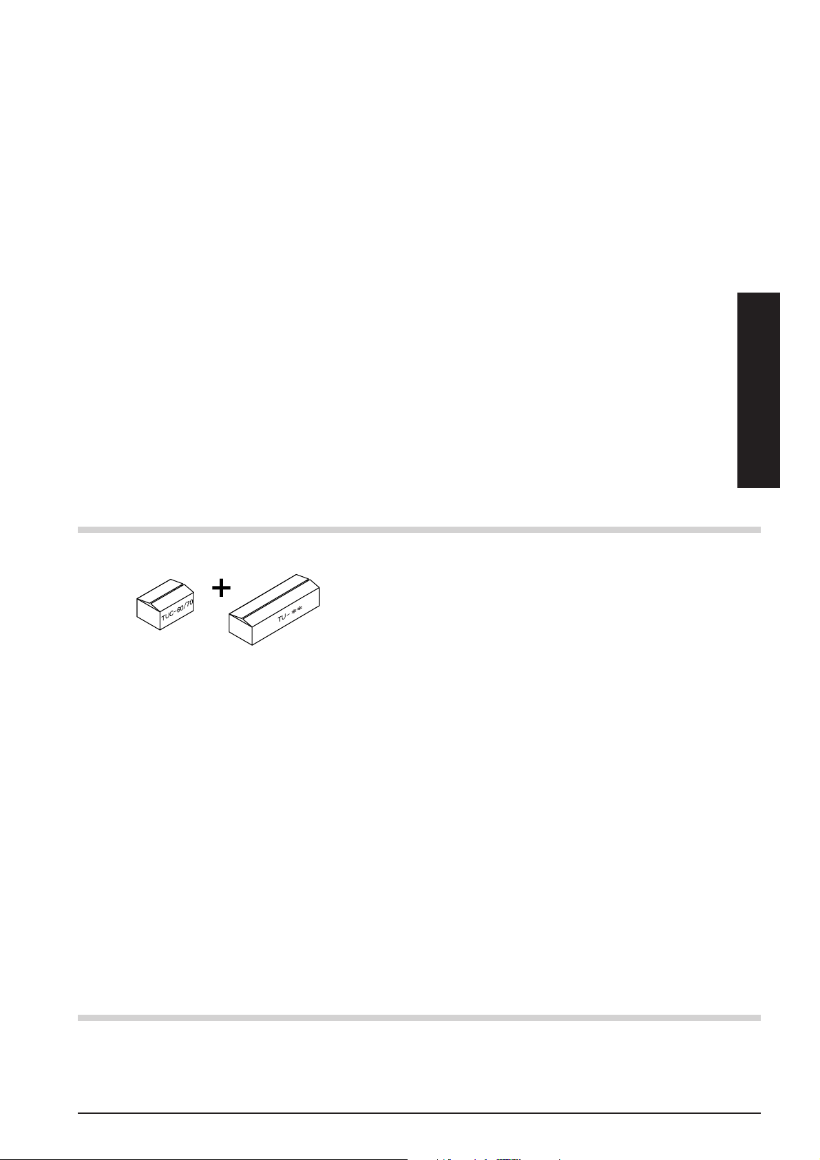
Table of Contents
To Ensure Safe Use.................................................................................................................. 2
About the Labels Affixed to the Unit............................................................... 4
1. System Configuration..................................................................................................................... 5
2. Confirmation of Included Items ................................................................................................... 5
3. Installation and Assembly ............................................................................................................. 6
4. Operation Panel ............................................................................................................................... 9
5. Adjusting the Sensor's Position .................................................................................................. 9
6. Operating Conditions for the TU ............................................................................................... 10
7. Loading Material ............................................................................................................................ 11
8. Starting Operation ......................................................................................................................... 14
9. Removing Material......................................................................................................................... 15
10. Maintenance ....................................................................................................................................15
11. What to Do If... ................................................................................................................................ 16
12. Specifications .................................................................................................................................17
ENGLISH
Automatic media take-up unit are packed separately in two boxes.
"TU-**" includes four types: the TU-60, TU-70, TU-400, and TU-500.
The combinations with the machine model you’re using are as follows.
TUC-60/70
(Controller)
· Automatic media take-up unit for the FJ-50.................................. The TU-70 and the TUC-60/70 make up a set.
This manual refers to the TU-70 and the TUC-60/70 collectively as the "TU-70."
· Automatic media take-up unit for the FJ-40.................................. The TU-60 and the TUC-60/70 make up a set.
This manual refers to the TU-60 and the TUC-60/70 collectively as the "TU-60."
· Automatic media take-up unit for the CJ-500/FJ-50. .................... The TU-500 and the TUC-60/70 make up a set.
This manual refers to the TU-500 and the TUC-60/70 collectively as the "TU-500."
· Automatic media take-up unit for the CJ-400/FJ-40. .................... The TU-400 and the TUC-60/70 make up a set.
This manual refers to the TU-400 and the TUC-60/70 collectively as the "TU-400."
In this manual, the following conventions are used to refer to different models that have items in common.
TU-60/70 .............. TU-60 and TU-70 CJ....................CJ-500 and CJ-400
TU-400/500 .......... TU-400 and TU-500 FJ ....................FJ-50 and FJ-40
TU ........................ TU-60, TU-70, TU-400 and TU-500 CJ/FJ...............CJ-500, CJ-400, FJ-50 and FJ-40
Stand..................... PNS-50, PNS-40, PNS-501 and PNS-401
TU-**
The figures in this manual depict mainly the CJ-500, PNS-501, and TU-500.
Windows® is a registered trademark or trademark of Microsoft® Corporation in the United States and/or other countries.
Other company names and product names are trademarks or registered trademarks of their respective holders.
Copyright © 1997 ROLAND DG CORPORATION
1
Page 4
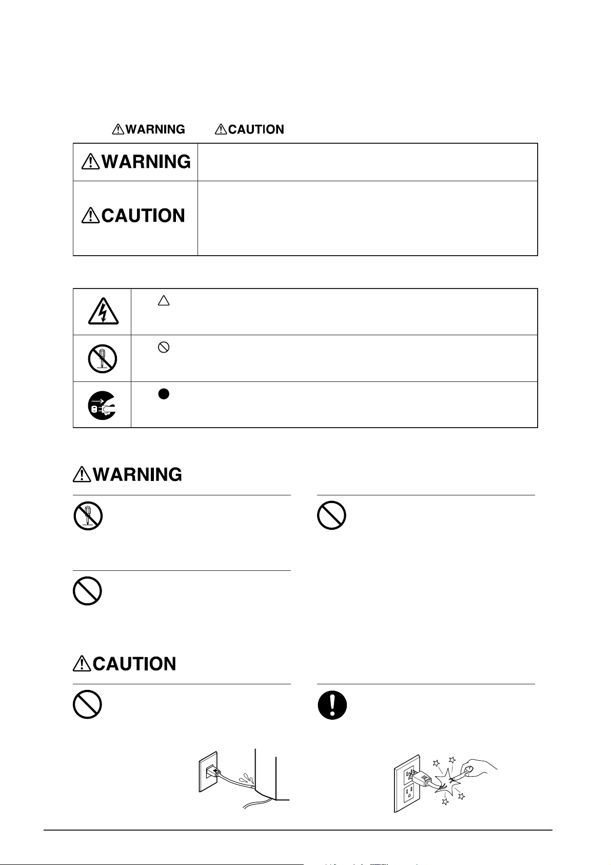
To Ensure Safe Use
About and Notices
Used for instructions intended to alert the user to the risk of death or severe
injury should the unit be used improperly.
Used for instructions intended to alert the user to the risk of injury or material
damage should the unit be used improperly.
* Material damage refers to damage or other adverse effects caused with
respect to the home and all its furnishings, as well to domestic animals or
pets.
About the Symbols
The symbol alerts the user to important instructions or warnings. The specific meaning of
the symbol is determined by the design contained within the triangle. The symbol at left means
"danger of electrocution."
The symbol alerts the user to items that must never be carried out (are forbidden). The
specific thing that must not be done is indicated by the design contained within the circle. The
symbol at left means the unit must never be disassembled.
The symbol alerts the user to things that must be carried out. The specific thing that must
be done is indicated by the design contained within the circle. The symbol at left means the
power-cord plug must be unplugged from the outlet.
Do not disassemble, repair, or
modify.
Doing so may lead to fire or abnormal
operation resulting in injury.
Do not use with any electrical power
supply that does not meet the
ratings displayed on the AC adapter.
Use with any other power supply may lead
to fire or electrocution.
Do not use with any power supply
other than the dedicated AC adapter.
Use with any other power supply may lead
to fire or electrocution.
Do not injure or modify the electrical
power cord, nor subject it to
excessive bends, twists, pulls,
binding, or pinching, nor place any
object of weight on it.
Doing so may
damage the
electrical power
cord, leading to
electrocution or
fire.
When unplugging the electrical AC
adapter from a power outlet, grasp
the plug, not the cord.
Unplugging by pulling the cord may damage
it, leading to fire or electrocution.
2
Page 5
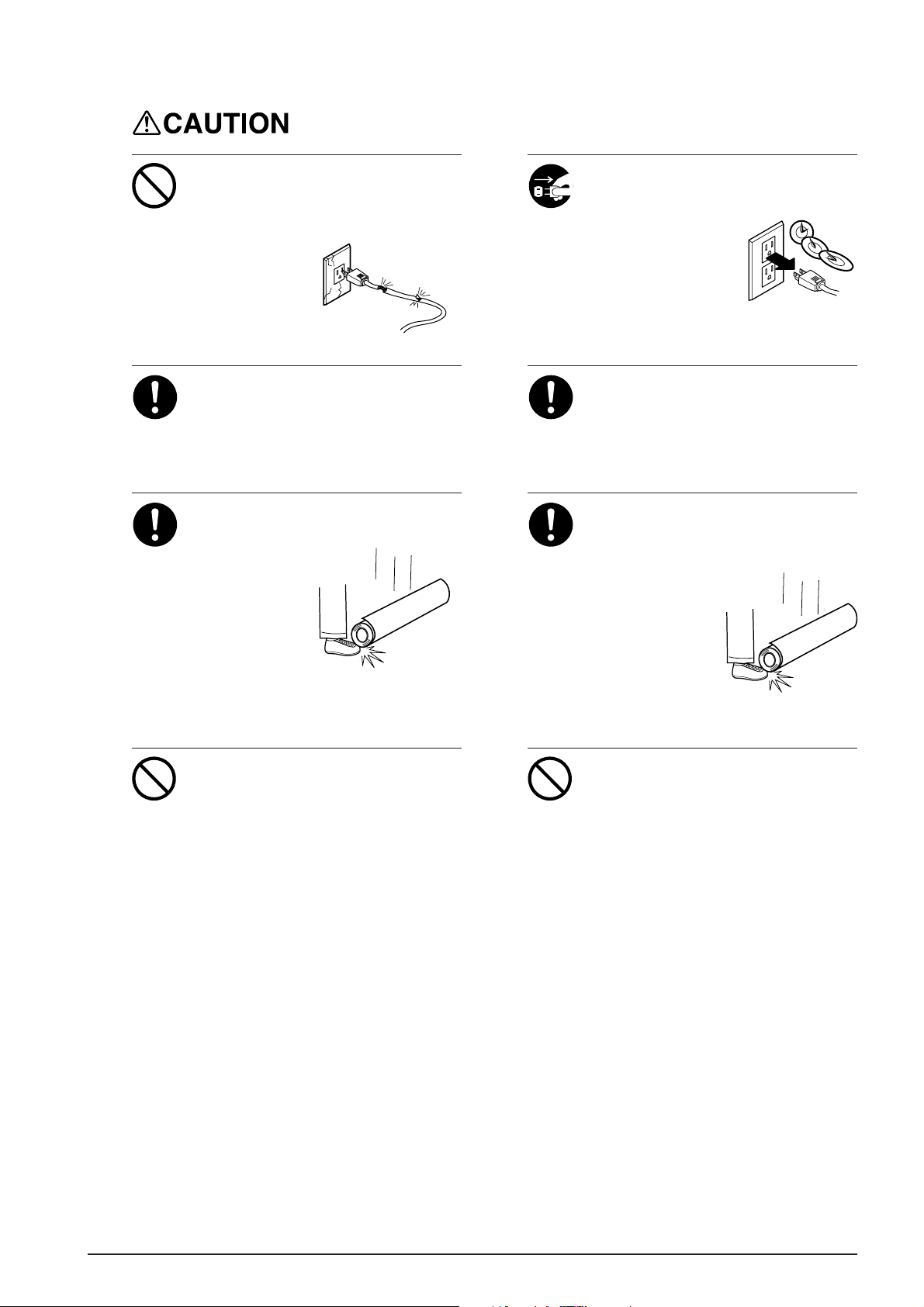
Do not use with a damaged power
cord or a power outlet that is loose
when the AC adapter is plugged in.
Use with any other power supply may lead
to fire or electrocution.
When not in use for extended
periods, unplug the power cord from
the electrical outlet.
Failure to do so may
result in danger of
shock, electrocution,
or fire due to
deterioration of the
electrical insulation.
Installation of the control box for the
TU is a task which must be carried
out by two or more persons.
Injury may result if attempted by one person
without assistance.
Roll material must be placed at a
predetermined shaft position.
Failure to do so
may allow the
material to fall,
leading to injury.
* For detailed information on loading material,
please refer to the CJ/FJ user's manual.
Do not attempt to change a roll
material while the power remains
switched on.
The take-up motor may be activated
unexpectedly while changing the roll,
leading to injury. The power must be
switched off before attempting to change
the material.
To secure the part in place, use the
bolt included with the unit.
A loose bolt or use of other than the
specified bolt may result in the falling of the
part, leading to injury.
Removal of taken-up roll material
from the TU is a task which must be
carried out by two or more persons.
Injury may result if
attempted by one
person without
assistance.
Do not allow the hands or hair to
touch the paper tube, flange, or
sheet during take-up.
The hands or hair may become caught.
3
Page 6
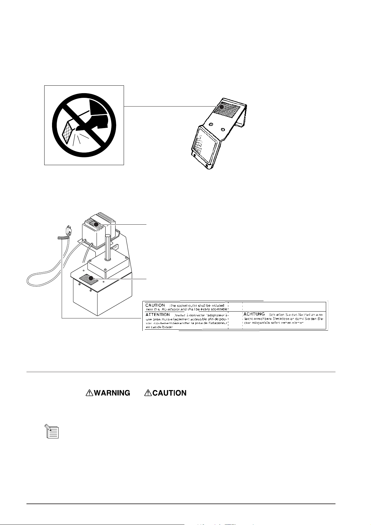
About the Labels Affixed to the Unit
These labels are affixed to the parts shown below.
The following figure describes the location.
Do not strike the mirror. Doing so
may damage the mirror, resulting
in incorrect operation.
Rating label
Use a rated power supply.
In addition to the
NOTICE
: Indicates information to prevent machine breakdown or malfunction and ensure correct use.
: Indicates a handy tip or advice regarding use.
Model name
Affixed to the 230 V/240 V adapter
and symbols, the symbols shown below are also used.
4
Page 7
1. System Configuration
Use with the configuration shown below.
CJ/FJ
+
STAND
TU-**
For information about
combination with the CJ or
FJ, see page 1.
Automatic take-up
of material feed
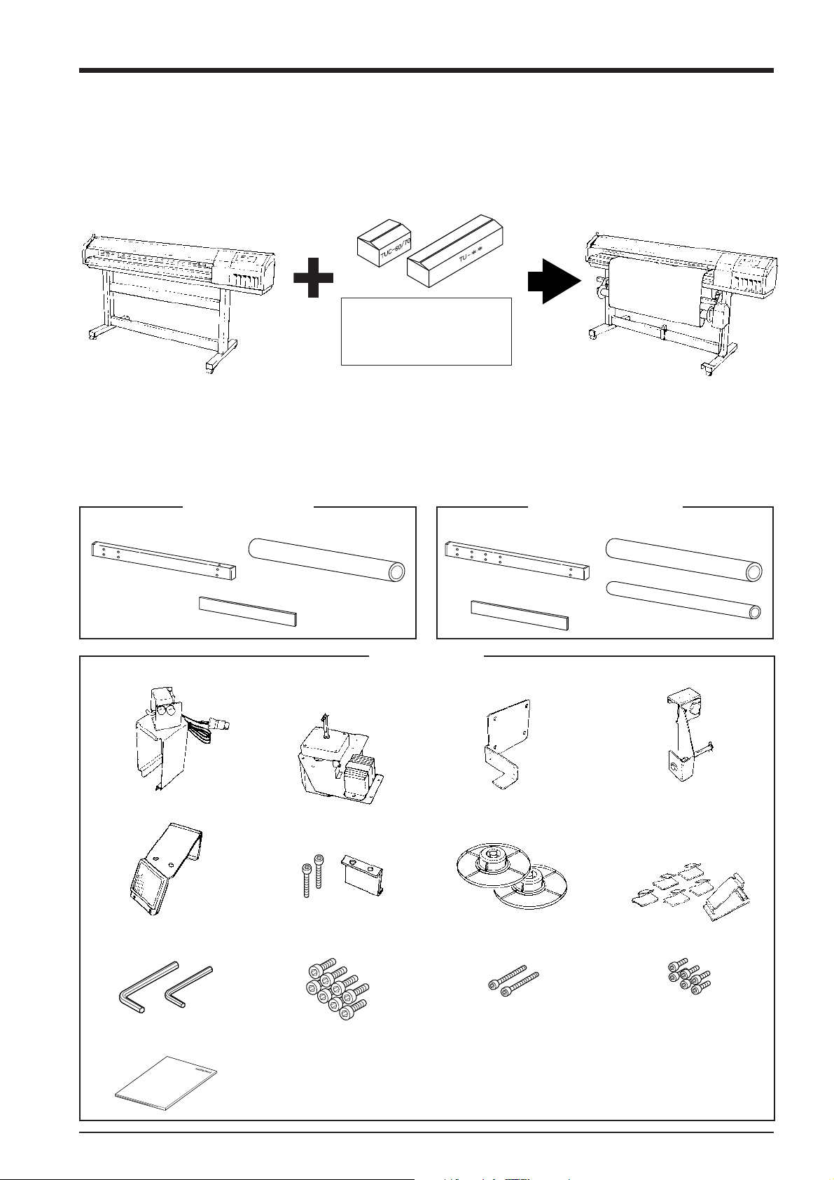
2. Confirmation of Included Items
The items are in the two packing cartons. Open both boxes and make sure all items are present.
TU-60, TU-70
Rail slider: 1 Paper tube: 1
Gauge: 1
Rail slider: 1 Paper tube: 1
Gauge: 1
TU-400, TU-500
Sensor: 1
Mirror: 1
1 each
TUC-60/70
Control box (including the
electrical adapter): 1
Frame: 1
Flange: 2Mirror stopper : 1 set
Cap screw (medium): 2Cap screw (large): 8 Cap screw (small): 6Hex wrench (large) / (small) :
Dancer roller: 1
Arm: 1
Cable retainer (large): 1
Cable retainer (small): 5
User's manual : 1
5
Page 8

3. Installation and Assembly
NOTICE
Installation of the control box is a
task which must be carried out by
two or more persons.
Injury may result if attempted by one person
without assistance.
Never install this unit in any of the following situations, as it could result in damage:
• Do not install the unit on an unstable surface.
• Places with excessive electrical noise.
• Places with excessive humidity or dust.
• The unit and AC adapter become hot during use. Avoid installation in an are a with poor heat-radiating
characteristics (poor ventilation).
• Avoid subjecting the unit to severe vibration or shocks.
• Places exposed to strong illumination or direct sunlight.
Do not strike the mirror. Doing so may damage the mirror, resulting in incorrect operation.
Be sure to connect the sensor cable securely so that it does not come loose or cause a poor connection during
use. Failure to connect securely may cause faulty operation or breakdown.
Be sure to switch off the power to the TU before connecting the sensor cable.
Before affixing the cable retainer, make sure the surface where the retainer is to be attached is clean and free of
dust or grime.
To secure the part in place, use the
bolt included with the unit.
A loose bolt or use of other than the
specified bolt may result in the falling of the
part, leading to injury.
Frame and Control Box Installation
Front
Frame
Cap screw (large)
Control box
Required tool
Large
* Move the media flange that is
at the rear side of the FJ to
the position where it doesn't
avoid frame and controller box
to be fixed.
When installing on the CJ,
carry out the installation with
the arm on the back of the
machine detached.
6
Page 9

Rail Slider Installation
Follow steps (1) and (2) in
sequence to install the rail
slider.
(2)
Required tool
Small
Front
Frame
Cap screw (small)
Cap screw (small)
Rail slider
If the screw holes for the small cap screws do
not line up, loosen all screws at the locations
shown in the figure.
While loosened, line up the screw holes and
secure in place with the small cap screws, then
tighten the loosened screws.
Top View
Stand leg
Rail slider
Cap screw (small)
Installing the Sensor and the Small
Retainer
(1)
Control box
Loosen
(Screws lined up in
the vertical direction)
Frame
Required tool
Small
Stay
Cap screw (medium)
Cable retainer (small)
Affix to the rear surface of the stand
and secure the sensor cable in place.
680 mm
(26-3/4 in.
Align by placing the
gauge packed with the
TU against this.
Open the sensor to the front and back
as shown, and fit it onto the stay.
Orientation of the
retainer (small)
±20 mm
±3/4 in.
)
Sensor cable
7
Page 10

Installing the Mirror
(3)
Secure in place with
the bolt.
(1)
(2)
Mirror
Stopper
Required tool
Small
Align with the tip of
the stand's metal
portion.
Power Cord Connection and Large Retainer Installation
Attach the retainer (large) to the back of the stand, and arrange the cord
connected to the main unit so that it is secured in place as shown in the figure.
Rear
The configuration of the AC adapter varies
according to regional differences in
voltage. Please note that the descriptions in
this manual are for the 117 V adapter.
Arm Installation
Front
Stay
Arrange the cord so that the end
that plugs into the main unit is
extended to the front from under
the stay on the stand.
Loosen the mounting screws.
Rail slider
Arm
8
Page 11

4. Operation Panel
AUTO
Material is taken up automatically
when material has been fed into the
sensor's detection area.
Power switch
MANUAL
The material is taken up manually.
OFF
No material take-up occurs, even when
material has been fed into the sensor's
detection area.
BACKWARD
Material take-up is in
the direction shown at
right.
FORWARD
Material take-up is in
the direction shown at
right.
5. Adjusting the Sensor's Position
Turn on the power. Two LEDs
1
(green and red) light up.
Sensor detection area
The TU performs material take-up when
material is fed into this area.
Green LED
Red LED
Loosen the screw as shown in the
2
figure, and adjust the angle of the
sensor so that it is aligned with
the mirror.
Screw
Rear
Tighten the adjustment screw
3
securely at the angle where the
red LED has gone dark.
Sensor
LED goes dark
Front
CJ/FJ
Mirror
Stand
9
Page 12

6. Operating Conditions for the TU
The TU takes up material fed from the CJ/FJ. Performing an operation to pull out material from the CJ/FJ generates corresponding force,
and so the CJ/FJ displays the error message, and operation stops. When performing printing in particular, such a stop in operation may
affect the printing extremely, such as misalignment of the printing location.
*Material can not be taken up with TU when CJ performs cutting. TU can be used only when printing.
OK NO GOOD
CJ/FJCJ/FJ
Material feed
Return of
pulled-out material
Take-up of fed material
Take-up of
fed material
TUTU
MOTOR ERROR
TURN OFF POWER
The CJ/FJ stops
operation
When using the TU, make the settings for the following conditions.
For Both the CJ and the FJ
• At the display menu, set [AUTO SHEET CUT] to [DISABLE].
• Do not use the [SHEET CUT] key to separate the material.
• Do not use the
or keys to return the material.
For the CJ Only
• Turn off the cutting function on the program you're using.
• From the display menu, set [PREFEED] to [DISABLE].
• From the display menu, select something other than [ROLL] for the material.
• Do not perform automatic detection of the base point or align point when loading
material.
• When loading material, use the right-hand grit roller (to ensure that the material overhangs the TU sensor area).
For the FJ Only
• Load the material so that it is close to the right-hand side (to ensure that the material overhangs the TU sensor area).
10
Page 13

7. Loading Material
NOTICE
Do not attempt to change a roll
material while the power remains
switched on.
The take-up motor may be activated
unexpectedly while changing the roll,
leading to injury. The power must be
switched off before attempting to change
the material.
When in the manual mode, make sure there is some slack in the material before attempting to perform take-up.
Roll material must be placed at a
predetermined shaft position.
Failure to do so may allow the material to
fall, leading to injury.
* For detailed informa-
Mounting the Flange and Paper Tube
Pull out the stopper.
1
Align the flange with the
groove on the shaft, and press
2
in all the way.
tion on loading
material, please refer to
the CJ/FJ user's
manual.
Insert the stopper.
3
Follow steps 1 to 3 to mount the
4
flange for the frame as well.
Tighten the mounting screws securely .
Mount the paper tube.
5
6
When using the core from used-up rolled material as the paper tube
When mounting the paper tube on the flanges, make sure that
the paper tube fits snugly. Attempting to take up material when
the paper tube is not stable may cause problems such as the paper tube coming loose. The outer diameter of the flange portion
where the paper tube is fitted is shown below.
Side view of flange
76.2 mm
(3 in.)
50.8 mm
(2 in.)
Make sure the margin described below is present between
each flange and the edge of the material. Attempting to take up
material when no margin is present may cause the material to
touch the flange and result in faulty take-up.
Sheet
20 mm (13/16 in.) or more
Paper tube
FlangeFlange
11
Page 14

Loading Rolled Material
* For more information, see the user's manual for the CJ/FJ main unit.
CJ
[Correct]
Make sure the loaded material is straight and
without slack so that it will not come loose from
the pinch rollers during printing.
Side view of the CJ
No slack
Pinch roller
Top view of the CJ
Rolled Material
Pinch roller
Make the material
perpendicular to
the CJ
Rolled Material
25 mm
(1 in.) or
more
[Incorrect]
If the loaded material is crooked or slack in places, it may come loose from the pinch rollers during printing.
Side view of the CJ
Material is slack
Pinch roller
Rolled Material
Top view of the CJ
Rolled Material
FJ
To ensure correct feed, make sure the material pulled out from the roll is free of slack.
25 mm
(1 in.) or
more
Loaded sheet
is crooked
[Correct]
FJ rear
12
Entire material
stretched taut
[Incorrect]
FJ rear
Material is slack
Page 15

Securing the Material in Place
Forward Take-up (FORWARD)
The printed surface is moved to the outer side and taken up
Pull out material so that it is perpendicular to the paper
1
tube.
Front
Pull out the material and ensure a certain amount of slack,
as shown in the figure. Move the sheet loading lever to
3
secure the material in place.
To prevent the pulled-out material from becoming
crooked, secure with tape at the two edges and center, as
2
shown in the figure.
Move the [MANUAL] switch to the [FORWARD]
setting and take up one turn's worth of material.
4
After take-up, maintain slack as shown in the figure to keep
the material from being drawn taut by take-up.
Front <---
Backward Take-up (BACKWARD)
The printed surface is moved to the inner side and taken up
Pull out material so that it is perpendicular to the paper
1
tube.
Front
To prevent the pulled-out material from becoming
crooked, secure with tape at the two edges and center, as
2
shown in the figure.
13
Page 16

Pull out the material and ensure a certain amount of slack,
as shown in the figure. Move the sheet loading lever to
3
secure the material in place.
Front <---
Move the [MANUAL] switch to the [BACKWARD]
setting and take up one turn's worth of material.
4
After take-up, maintain slack as shown in the figure to
keep the material from being drawn taut by take-up.
8. Starting Operation
Do not allow the hands or hair to
touch the paper tube, flange, or
sheet during take-up.
The hands or hair may become caught.
NOTICE
Turn on the power.
1
During operation, do not enter the sensor's detection area. Doing so will result in excessive take-up and cause
printing to be interrupted.
When in the manual mode, make sure there is some slack in the material before attempting to perform take-up.
Set the desired direction of take-up.
2
Data is sent from the computer and
3
printing on the CJ/FJ starts.
14
Forward
Take-up
Backward
Take-up
Page 17

9. Removing Material
Removal of taken-up roll material
from the TU is a task which must be
carried out by two or more persons.
Injury may result if
attempted by one
person without
assistance.
Turn off the power.
1
Support the paper tube and material from
3
underneath to prevent from falling.
The second person loosens
the retaining screws and
4
moves the arm.
10.Maintenance
Cut off the piece of material from the roll.
2
Detach the paper tube and material from the flanges.
5
NOTICE
Be sure to turn off the power to the TU before cleaning.
Never attempt to oil or lubricate the mechanism.
Cleaning the Mirror and Sensor
Wipe clean with a dry cloth.
Grime on the mirror or sensor may cause material in the sensor's detection area not to be sensed correctly.
15
Page 18

11.What to Do If...
The CJ doesn't run
* If a message like the one shown at right appears on the CJ
MOTOR ERROR
TURN OFF POWER
Is the cutting function of the application software you're using not enabled?
Do not use in such modes.
Has the prefeed function on the CJ been set to [ENABLE]?
Change the setting to [DISABLE].
Have the control keys on the CJ been used to perform material return?
Do not use the CJ's keys to perform feed or return of the material.
Is the material selection on the CJ set to [EDGE] or [PIECE]?
Change the setting to [ROLL].
When loading the material, was automatic detection of the base point or align point performed?
Do not use the function for automatic detection of the base point or align point.
The FJ doesn't run
* If a message like the one shown at right appears on the FJ
MOTOR ERROR
TURN OFF POWER
Have the control keys on the FJ been used to perform material return?
Do not use the FJ's keys to perform feed or return of the material.
The TU doesn't take up material
Is the AUTO switch set to [OFF]?
Set the AUTO switch to match the direction of take-up.
Is the material loaded correctly on the paper tube?
Make sure the direction of material take-up matches the AUTO switch setting.
Is there some obstruction between the mirror and sensor?
If no corrective action is taken when the sensor has detected an obstruction, take-up is automatically switched off. Once this has
happens, no take-up is performed even if the obstruction is removed after feeding out the sheet from the sensor's detection area.
To restore the previous state, switch off the power to the TU, remove the obstruction, then switch the power back on.
Is material cutting being performed automatically?
At the display menu, set [AUTO SHEET CUT] to [DISABLE].
16
Page 19

Take-up of non-stiff material (such as synthetic paper, matte) is not straight
The problem is caused by wrinkling and slack in the material due to static
electricity.
If you're using the TU-400/500, insert the included dancer roller at the
area shown in the figure to maintain tension in the material.
If you're using the TU-60/70, insert the leftover core from used-up roll
material or one of the shafts included with the stand for the FJ (the PNS50/40).
Dancer roller (if using the TU-400/500)
or roll-material core or shaft (if using the
TU-60/70)
12. Specifications
TU-60 TU-70 TU-400 TU-500
Acceptable media widths
Material weight for which take-up is possible
Maximum material diameter after take-up
Speed during material take-up
Control switches
Power consumption
Acoustic noise level
Total weight of contents
Operating temperature
Operating humidity
Included items
Remarks
TUC-60/70
TU-**
TUC-60/70
TU-**
210—1050 mm 210—1300 mm 210—1125 mm 210—1371 mm
(8-1/4—41-5/16 in.) (8-1/4—51-1/8 in.) (8-1/4—44-1/4 in.) (8-1/4—53-15/16 in.)
17 kg (37.4 lb.) or less 20 kg (44 lb.) or less 17 kg (37.4 lb.) or less 20 kg (44 lb.) or less
180 mm (7-1/16 in.)
AUTO: 39 rpm MANUAL: 39 rpm
POWER, AUTO, MANUAL
Exclusive AC adapter DC+9.7 V 0.7 A +31 V 0.7 A
Take-up mode: 70 dB (A) or less (According to ISO7779)
6.5 kg (14.3 lb.)
2 kg (4.4 lb.) 2.5 kg (5.5 lb.) 2.5 kg (5.5 lb.) 3.0 kg (6.6 lb.)
5—40°C (41—104°F)
20—80% (non-condensing)
Frame x 1, Control box (including the electrical adapter) x 1, Flange x 2, Sensor x 1, Arm x 1,
Mirror x 1, Mirror stopper x 1 set, Hex wrench (large) / (Small) 1 each,
Cap screw (large) x 8, Cap screw (middle) x 2, Cap screw (middle) x 2, Cap screw (small) x 6,
Cable retainer (large) x 1, Cable retainer (small) x 5, User’s Manual x 1
Rail slider x 1, Paper tube x 1, Gauge x 1
The automatic take-up function on the TU cannot be used when performing any of the following operations on
the CJ/FJ.
• Automatic separation of the material, and separation of the material by pressing the [SHEET CUT] key.
• Return of the material using the or key.
• There is no material at the TU's sensor detection area.
[For the CJ only]
• Setting the prefeed function to [ENABLE].
• Enable the cutting function for the application software you’re using.
• From the display menu, select something other than [ROLL] for the material
• When loading material, automatic detection of the base point or align point was performed.
Rail slider x 1, Paper tube x 1, Gauge x 1, Dancer Roller x 1
17
Page 20

MEMO
18
Page 21

R8-990901
 Loading...